WO2020050103A1 - 仮想視点の制御装置及びその制御方法 - Google Patents
仮想視点の制御装置及びその制御方法 Download PDFInfo
- Publication number
- WO2020050103A1 WO2020050103A1 PCT/JP2019/033550 JP2019033550W WO2020050103A1 WO 2020050103 A1 WO2020050103 A1 WO 2020050103A1 JP 2019033550 W JP2019033550 W JP 2019033550W WO 2020050103 A1 WO2020050103 A1 WO 2020050103A1
- Authority
- WO
- WIPO (PCT)
- Prior art keywords
- virtual viewpoint
- virtual camera
- virtual
- control
- control device
- Prior art date
- Legal status (The legal status is an assumption and is not a legal conclusion. Google has not performed a legal analysis and makes no representation as to the accuracy of the status listed.)
- Ceased
Links
Images







Classifications
-
- H—ELECTRICITY
- H04—ELECTRIC COMMUNICATION TECHNIQUE
- H04N—PICTORIAL COMMUNICATION, e.g. TELEVISION
- H04N13/00—Stereoscopic video systems; Multi-view video systems; Details thereof
- H04N13/20—Image signal generators
- H04N13/275—Image signal generators from three-dimensional [3D] object models, e.g. computer-generated stereoscopic image signals
- H04N13/279—Image signal generators from three-dimensional [3D] object models, e.g. computer-generated stereoscopic image signals the virtual viewpoint locations being selected by the viewers or determined by tracking
-
- H—ELECTRICITY
- H04—ELECTRIC COMMUNICATION TECHNIQUE
- H04N—PICTORIAL COMMUNICATION, e.g. TELEVISION
- H04N5/00—Details of television systems
- H04N5/222—Studio circuitry; Studio devices; Studio equipment
- H04N5/262—Studio circuits, e.g. for mixing, switching-over, change of character of image, other special effects ; Cameras specially adapted for the electronic generation of special effects
- H04N5/2628—Alteration of picture size, shape, position or orientation, e.g. zooming, rotation, rolling, perspective, translation
-
- G—PHYSICS
- G06—COMPUTING OR CALCULATING; COUNTING
- G06F—ELECTRIC DIGITAL DATA PROCESSING
- G06F3/00—Input arrangements for transferring data to be processed into a form capable of being handled by the computer; Output arrangements for transferring data from processing unit to output unit, e.g. interface arrangements
- G06F3/01—Input arrangements or combined input and output arrangements for interaction between user and computer
- G06F3/048—Interaction techniques based on graphical user interfaces [GUI]
- G06F3/0484—Interaction techniques based on graphical user interfaces [GUI] for the control of specific functions or operations, e.g. selecting or manipulating an object, an image or a displayed text element, setting a parameter value or selecting a range
-
- G—PHYSICS
- G06—COMPUTING OR CALCULATING; COUNTING
- G06T—IMAGE DATA PROCESSING OR GENERATION, IN GENERAL
- G06T15/00—Three-dimensional [3D] image rendering
- G06T15/10—Geometric effects
- G06T15/20—Perspective computation
-
- G—PHYSICS
- G06—COMPUTING OR CALCULATING; COUNTING
- G06T—IMAGE DATA PROCESSING OR GENERATION, IN GENERAL
- G06T19/00—Manipulating three-dimensional [3D] models or images for computer graphics
-
- H—ELECTRICITY
- H04—ELECTRIC COMMUNICATION TECHNIQUE
- H04N—PICTORIAL COMMUNICATION, e.g. TELEVISION
- H04N13/00—Stereoscopic video systems; Multi-view video systems; Details thereof
- H04N13/20—Image signal generators
- H04N13/282—Image signal generators for generating image signals corresponding to three or more geometrical viewpoints, e.g. multi-view systems
-
- H—ELECTRICITY
- H04—ELECTRIC COMMUNICATION TECHNIQUE
- H04N—PICTORIAL COMMUNICATION, e.g. TELEVISION
- H04N13/00—Stereoscopic video systems; Multi-view video systems; Details thereof
- H04N13/20—Image signal generators
- H04N13/293—Generating mixed stereoscopic images; Generating mixed monoscopic and stereoscopic images, e.g. a stereoscopic image overlay window on a monoscopic image background
-
- H—ELECTRICITY
- H04—ELECTRIC COMMUNICATION TECHNIQUE
- H04N—PICTORIAL COMMUNICATION, e.g. TELEVISION
- H04N23/00—Cameras or camera modules comprising electronic image sensors; Control thereof
- H04N23/90—Arrangement of cameras or camera modules, e.g. multiple cameras in TV studios or sports stadiums
Definitions
- the present invention relates to a virtual viewpoint control device and a control method thereof.
- Patent Literature 1 discloses a technique in which an operation history performed by another user in the past is retained and presented to the user.
- the operation of the virtual viewpoint image can be assisted by presenting the operation performed in the past to the user, but the operation itself performed by the user cannot be assisted.
- operations to create images that cannot be obtained with a real camera such as displaying the player's play on the ground observed from the ground, behind the seats, outside the ceiling of the dome stadium, etc. Is performed, the position and posture of the virtual camera may be lost.
- a virtual camera control device has the following configuration. That is, A control device that controls the virtual camera according to a user operation related to an operation of a virtual camera for generating a virtual viewpoint image, Receiving means for receiving the user operation; Determining means for determining whether to restrict the operation of the virtual camera according to the user operation received by the receiving means, according to whether a predetermined condition regarding the virtual camera is satisfied. .
- FIG. 1 is a block diagram illustrating an example of an overall configuration of an image processing system according to an embodiment.
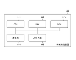
- FIG. 3 is a block diagram illustrating a hardware configuration example of an information processing device.
- FIG. 2 is a block diagram illustrating a functional configuration example of an information processing device.
- FIG. 2 illustrates a configuration of an input / output unit in the information processing device.
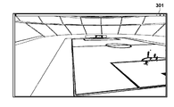
- FIG. 4 is a diagram illustrating a camera view window.
- FIG. 3 is a schematic diagram illustrating a virtual camera and a coordinate system of world coordinates.
- 5 is a flowchart illustrating processing of the image processing system according to the first embodiment.
- FIG. 3 is a schematic diagram showing a state of operation of a virtual camera and a person who is a subject.
- FIG. 5 is a diagram illustrating a virtual viewpoint image based on initial parameters.
- 8a is a schematic diagram showing a vector indicating the direction of the destination virtual camera and a vector of a normal to the boundary surface of the movable range, and 8b shows an angle between the two vectors shown in 8a.
- 9a is a schematic diagram showing a vector indicating the direction of the destination virtual camera and a vector of a normal line of the boundary of the movable range, and 9b shows an angle between the two vectors indicated by 9a.
- FIG. 4 is a diagram illustrating a virtual viewpoint image by a virtual camera 901.
- FIG. 9 is a flowchart illustrating processing of the image processing system according to the second embodiment.
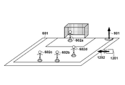
- FIG. 5 is a diagram schematically illustrating a state of a change in the attitude of the virtual camera.
- FIG. 5 is a diagram schematically illustrating a state of a change in the attitude of the virtual camera.
- FIG. 3 is a diagram illustrating a virtual viewpoint image by a virtual camera 1201.
- FIG. 12 is a diagram illustrating a virtual viewpoint image by a virtual camera 1203.
- 11 is a flowchart illustrating a process of the image processing system according to the third embodiment.
- FIG. 1A is a diagram illustrating an overall configuration of an image processing system 10 according to the first embodiment.
- the image processing system 10 includes an imaging system 101, an image generation server 102, and an information processing device 103.
- the image processing system 10 can generate a virtual viewpoint image.
- the photographing system 101 arranges a plurality of photographing devices (cameras) at different positions and synchronously photographs a plurality of images from multiple viewpoints.
- the imaging system 101 transmits a plurality of images synchronously captured from multiple viewpoints to the image generation server 102.
- the image generation server 102 generates a virtual viewpoint image viewed from the virtual camera based on a plurality of images synchronously shot from multiple viewpoints.
- a virtual camera is a virtual camera that can move freely in a shooting space. With the virtual camera, an image viewed from a different viewpoint from any camera of the imaging system 101, that is, a virtual viewpoint image can be captured.
- the viewpoint (virtual viewpoint) of the virtual camera is represented by camera parameters determined by the information processing device 103 described later.
- the image generation server 102 sequentially generates a virtual viewpoint image from the received plurality of images. That is, it is possible to generate a live virtual viewpoint image.
- a live virtual viewpoint image that can be generated by the image processing system 10 is a virtual viewpoint image based on a captured image captured by the imaging system 101 at a time that takes into account processing delays in the imaging system 101 and the image generation server 102 with respect to the current time. It is.
- the image generation server 102 has a database and has a function of recording the received plurality of images. It is possible to generate a past virtual viewpoint image, that is, a replay virtual viewpoint image, from a plurality of images recorded in the database.
- the replay virtual viewpoint image is a virtual viewpoint image based on an image captured by the imaging system 101 at an arbitrary time.
- image will be described as including both concepts of a moving image (image) and a still image. That is, the image processing system 10 can process both still images and moving images.
- the image generation server 102 can also perform image processing such as measurement of statistics on the created image. For example, it is possible to measure how much the foreground and the background are projected in the virtual viewpoint image.
- the information processing device 103 controls the virtual camera and determines camera parameters representing the viewpoint of the virtual camera.
- the camera parameters of the virtual camera include parameters for designating at least one of the position, posture, zoom, and time.
- the position of the virtual camera specified by the camera parameter indicates, for example, three-dimensional coordinates, and may be indicated by coordinates in a three-axis orthogonal coordinate system of an X axis, a Y axis, and a Z axis.
- the position specified by the camera parameters of the virtual camera indicates coordinates, and is composed of three-axis parameters of an X-axis, a Y-axis, and a Z-axis.
- the origin of the coordinates can be set at an arbitrary position in the photographing space.
- the posture of the virtual camera specified by the camera parameter can be indicated by, for example, a rotation angle around three axes of pan, tilt, and roll.
- the posture of the virtual camera specified by the camera parameters can be composed of three-axis parameters of pan, tilt, and roll.
- the zoom of the virtual camera specified by the camera parameter is indicated by, for example, one axis of the focal length.
- the time is a one-axis parameter. Therefore, the camera parameters of the virtual camera of this embodiment have at least eight axes (position: three axes, attitude: three axes, focal length: one axis, time: one axis).
- the information processing device 103 can control these eight axes. Note that the camera parameters that can be controlled by the information processing apparatus 103 may include parameters that define other elements, or may not include all of the eight-axis parameters described above.
- the information processing apparatus 103 transmits the determined camera parameters of the virtual camera to the image generation server 102.
- the image generation server 102 generates a virtual viewpoint image based on the camera parameters received from the information processing device 103, and transmits the generated virtual viewpoint image to the information processing device 103.
- the information processing apparatus 103 displays the virtual viewpoint image received from the image generation server 102 on a camera view window 301 (described later with reference to FIGS. 2 and 3). Note that, as in the present embodiment, one information processing apparatus 103 may generate a live virtual viewpoint image and a replay virtual viewpoint image, or two or more information processing apparatuses 103 may be prepared and a live virtual viewpoint image may be generated. The image and the replay virtual viewpoint image may be generated by different information processing apparatuses 103.
- FIG. 1B is a diagram illustrating a hardware configuration of the information processing apparatus 103.
- the CPU 111 controls the entire information processing apparatus 103 using computer programs and data stored in the RAM 112 and the ROM 113.
- the RAM 112 temporarily stores data supplied from the outside via the communication unit 114, such as a computer program read from the ROM 113 and an intermediate result of calculation.
- the ROM 113 holds computer programs and data that do not need to be changed.
- the communication unit 114 has communication means such as Ethernet and USB, and communicates with the image generation server 102.
- the input / output unit 115 has a plurality of controllers for controlling the virtual camera and a plurality of display units for displaying the status of the virtual camera and the like.
- FIG. 2 is a diagram illustrating the input / output unit 115.
- the display unit 201 displays a camera view window 301.
- the camera view window 301 is a window for displaying a virtual viewpoint image received from the image generation server 102.
- the input / output unit 115 has a controller as a receiving unit that receives an instruction for controlling the virtual camera by a user operation. The user can perform an operation for changing the position / posture of the virtual camera via the controller.
- the three-axis controller 202a and the three-axis controller 202b are controllers capable of operating three axes. Arbitrary control can be assigned to each axis by setting.
- the three-axis controller 202a controls three axes of an X axis, a Y axis, and a Z axis for specifying the position of the virtual camera. Further, the three-axis controller 202b controls, for example, three axes of pan, tilt, and roll for designating the posture of the virtual camera.
- the zoom controller 203 is a controller that controls the zoom of the virtual camera.
- the replay controller 204 is a controller that controls a function for generating a replay virtual viewpoint image.
- the replay controller 204 also assigns control of the time of the virtual camera.
- the input / output unit 115 illustrated in FIG. 2 is merely an example, and is not limited to the illustrated example.
- the input / output unit 115 may include two or more display units. Further, the number and types of controllers included in the input / output unit 115 are not limited to the illustrated configuration.
- FIG. 3 is a diagram showing an example of the camera view window 301.
- the camera view window 301 is displayed on the display unit 201, for example.
- a virtual viewpoint image of a person playing soccer in a stadium as a subject is generated.
- the camera view window 301 is a display area for displaying the virtual viewpoint image received from the image generation server 102.
- This virtual viewpoint image is a virtual viewpoint image viewed from a virtual camera controlled by the user.
- the information processing apparatus 103 can also display a past virtual viewpoint image in a recorded range.
- the latest image capable of creating a virtual viewpoint image is displayed. If the processing time of the virtual viewpoint image is almost zero, the image at the current time is displayed in real time. Can be considered.
- FIG. 4 is a schematic diagram showing a virtual camera and a coordinate system of world coordinates.
- the X axis 411 indicates movement on a two-dimensional plane, and is a parameter indicating movement in the long side direction (direction parallel to the side line) of the soccer field.
- the Y axis 412 indicates a movement on a two-dimensional plane, and is a parameter indicating the movement of the soccer ground in the short side direction (direction parallel to the center line).
- the Z axis 413 is a parameter indicating movement in the height direction, and is a parameter indicating movement in the vertical direction with respect to the ground.
- the direction of each axis is not limited to this.
- any axes shown here may be interchanged.
- the Y axis 412 may be in the vertical direction
- the X axis 411 may be in the vertical direction.
- one of the remaining two axes is parallel to the long side direction of the soccer field, and the other is parallel to the short stitch direction.
- the positive direction of each axis may be either direction.
- the vertical direction as the Z-axis has a positive value in the upward direction, but may have a negative value.
- the X-axis, Y-axis, and Z-axis are orthogonal, and it suffices that any one point in space can be indicated using three-axis parameters. The direction of the axis may be changed.
- the tilt 404 is a parameter indicating that the optical axis of the virtual camera is rotated up and down, and is the rotation of the virtual camera around the tilt axis 401.
- the roll 405 is a parameter indicating the rotation of the virtual camera about the optical axis, and is the rotation of the virtual camera about the roll axis 402.
- Pan 406 is a parameter for rotating the optical axis of the virtual camera in the left-right direction, and is rotation of the virtual camera about the pan axis 403.
- FIG. 1C is a block diagram illustrating a functional configuration example of the information processing device 103 functioning as a virtual camera control device that controls a virtual camera in accordance with a user operation instructing an operation of the virtual camera for generating a virtual viewpoint image.
- the parameter generation unit 151 After setting the initial parameters of the virtual camera, the parameter generation unit 151 generates parameters for controlling the operation of the virtual camera according to a user operation.
- the operation of the virtual camera includes movement of the position of the virtual camera, movement of the direction, change of zoom, and the like.
- the restriction unit 152 determines whether or not to restrict the operation of the virtual camera according to the received user operation according to whether or not a predetermined condition regarding the virtual camera is satisfied.
- the restricting unit 152 determines whether the position after the movement of the virtual camera specified by the user operation is within a predetermined movable range. Then, when it is determined that the position after the movement is out of the movable range, the restricting unit 152 restricts the operation of the virtual camera by the user operation. In the present embodiment, the user operation is invalidated by this restriction.
- the constraint release unit 153 releases the restriction by the constraint unit 152 when a predetermined release condition is satisfied for the virtual camera after the movement by the user operation. For example, when a predetermined condition regarding the above-described virtual camera is satisfied, the restriction on the virtual camera is released. In the present embodiment, even if the virtual camera moves out of the movable range, if the direction of the virtual camera satisfies the release condition, the restriction by the restriction unit 152 is released, and the virtual camera is moved by the user operation. You.
- the autopilot execution unit 160 is a configuration used in the third embodiment, and can be omitted in the first and second embodiments.
- the parameter changing unit 154 changes the camera parameters of the virtual camera according to the operation content of the virtual camera.
- FIG. 5 is a flowchart showing the processing of the image processing system 10 according to the first embodiment.
- FIG. 6 is a diagram schematically showing the operation of the virtual camera and a person as a subject.
- Reference numeral 601 denotes a ground (ground) near a penalty area in a soccer stadium where a virtual viewpoint image is to be generated, and reference numerals 602a, 602b, 602c, and 602d denote players in the penalty area.
- Reference numerals 603a to 603c schematically show virtual cameras having a position / posture set by parameters. In FIG. 5, it is assumed that the virtual camera 603a has been set by the initial parameters.
- the image generation server 102 generates a virtual viewpoint image based on the initial parameters of the virtual camera specified by the information processing device 103 (Step S502).
- a virtual viewpoint image in the virtual camera 603a of the initial parameter is generated.
- the information processing device 103 receives the virtual viewpoint image from the image generation server 102 and displays the image on the camera view window 301 of the display unit 201, for example, as shown in FIG.
- the virtual viewpoint image illustrated in FIG. 7 is, for example, an image captured by the virtual camera 603a, that is, a virtual viewpoint image generated for the virtual camera 603a.
- the user operates the three-axis controllers 202a and 202b, the zoom controller 203, and the like to control the camera parameters of the virtual camera while viewing the virtual viewpoint image displayed on the display unit 201.
- the parameter generation unit 151 receives these user operations (step S503). For example, it is assumed that the user operates the three-axis controller 202a to change the parameters of the Z axis and move the position of the virtual camera in the minus direction of the Z axis.
- the parameter generation unit 151 Upon receiving the user operation of the virtual camera, the parameter generation unit 151 generates camera parameters of the destination virtual camera according to the content of the instruction (Step S504). For example, a camera parameter indicating the virtual camera 603b is generated as a camera parameter of a destination virtual camera by a user operation by performing an operation in the minus direction in the Z-axis direction.
- the restriction unit 152 of the information processing device 103 determines whether the position of the virtual camera 603b indicated by the parameter generated in step S504 is within the movable range of the virtual camera (step S505).
- a setting area defined as the Z-axis direction is from the ground plane of the stadium to the top of the stadium as shown in FIG. 3, and the X and Y-axis directions are up to the audience seat position. Shall be used.
- the definition of the setting area as the movable range is not limited to this.
- the setting area may be any area in the three-dimensional space where the three-dimensional model of the object exists.
- the stadium not only the stadium but also a wide area may be defined outside the stadium when a wide area model can be prepared.
- the area in which a virtual viewpoint image can be created is limited due to processing capacity, shooting conditions, and the like, for example, in the case of soccer, the movable range is in the field of the ground or in the penalty area. It may be set to a narrow range.
- the area where the three-dimensional model exists may be an area where at least one of the three-dimensional model of the foreground object, the three-dimensional model of the background object, and the three-dimensional model of the virtual object exists.
- an area where at least one of a foreground object corresponding to a player or the like, a background object corresponding to a stadium or the like, and a virtual object not existing in the real space is set as a movable range.
- You may.
- an area included in at least one of a plurality of captured images acquired by a plurality of cameras included in the imaging system 101 may be set as a movable range.
- the restricting unit 152 does not restrict the user operation.
- the parameter changing unit 154 changes the camera parameters of the virtual camera to the camera parameters generated by the parameter generating unit 151 in Step S504 (Step S508).
- the parameter changing unit 154 changes the parameters of the virtual camera to the parameters acquired by the parameter generating unit 151 in step S504. Thereafter, a virtual viewpoint image is generated by the virtual camera 603b.
- step S506 if the position of the destination virtual camera is not within the movable range (NO in step S505), the process proceeds to step S506.
- the constraint unit 152 executes the constraint by invalidating the user operation.
- the constraint release unit 153 has instructed the release of the constraint, the movement of the virtual camera according to the user operation is executed.
- steps S506 to S507 are an example of a constraint and constraint release operation by the constraint unit 152 and the constraint release unit 153.
- the constraint release unit 153 obtains the angle between the normal of the boundary surface of the movable range and the vector of the camera parameter of the destination virtual camera (step). S506).
- the boundary surface of the movable range exists between the position of the virtual camera indicated by the current camera parameter and the position of the virtual camera indicated by the camera parameter changed by the user operation.
- the normal direction of the boundary is defined as a reference normal vector. In the present embodiment, it is assumed that the inside of the movable range, that is, the side on which the virtual camera can move, is the front side of the boundary surface, and the normal vector of the boundary surface faces the inside of the movable range. However, the normal direction is not limited to this.
- a vector (hereinafter, a direction vector) indicating a line-of-sight direction corresponding to the direction of the virtual camera is determined by three parameters, defined by camera parameters, indicating pan, tilt, and roll of the virtual camera. The angle between the two vectors is calculated.
- reference numeral 8a is a schematic diagram showing the direction vector 802 of the virtual camera and the normal vector 801 of the boundary of the movable range obtained from the camera parameters of the destination virtual camera.
- the normal vector 801 is a vector indicating the normal line of the boundary surface of the movable range, and in this example, it is assumed that the ground is equivalent to the boundary surface.
- the direction vector 802 is a vector indicating the direction of the virtual camera, which is determined based on the camera parameters of the destination virtual camera.
- a schematic diagram 8b of FIG. 8 is a schematic diagram showing an angle between the normal vector 801 and the direction vector 802 shown in the schematic diagram 8a. It is assumed that an angle between the normal vector 801 and the direction vector 802 is measured to obtain an angle 803.
- the angle 803 is an obtuse angle having an angle larger than 90 degrees.
- the constraint release unit 153 When the angle between the normal vector and the direction vector is within a predetermined angle range, the constraint release unit 153 outputs a release instruction to release the restriction by the restriction unit 152.
- the constraint release unit 153 determines that the release condition is satisfied, and outputs a release instruction.
- the boundary surface of the movable range is a horizontal plane and the normal vector is vertically upward as in the example of FIG. 8, the condition that the angle between the normal vector and the direction vector is equal to or less than the threshold value is determined by the direction of the virtual camera.
- step S506 when the angle between the two vectors obtained in step S506 is equal to or smaller than the threshold (YES in step S507), the process proceeds to step S508, otherwise (NO in step S507).
- the threshold value is 90 degrees
- the process returns to step S502. That is, the constraint release unit 153 does not output a release instruction, and the constraint unit 152 invalidates the user operation.
- the restriction unit 152 discards the camera parameters of the destination virtual camera, and the parameter change unit 154 does not change the parameters. As a result, shooting by the virtual camera 603a is maintained. As a result, the movement of the virtual camera is restricted within the movable range, thereby preventing the user from losing the position and orientation of the virtual camera.
- the threshold is set to 90 degrees, but the present invention is not limited to this.
- a schematic diagram 9a in FIG. 9 is a schematic diagram showing a state at this time.
- the destination virtual camera 901 specified by the user operation has the same three-dimensional position as the virtual camera 603c (the values of the X-axis, Y-axis, and Z-axis parameters are the same), but the direction (direction vector 902). Is different from the virtual camera 603c.
- a schematic diagram 9b in FIG. 9 is a schematic diagram showing an angle between the direction vector 902 and the normal vector 801 shown in the schematic diagram 9a.
- an angle 903 is obtained.
- the angle 903 is an angle (acute angle) of 90 degrees or less.
- the constraint release unit 153 determines that the release condition (the angle is equal to or smaller than the threshold) is satisfied, issues a release instruction to the restricting unit 152, and releases the restriction by the restricting unit 152.
- step S508 in which the parameter changing unit 154 changes the camera parameter of the virtual camera to the camera parameter of the movement destination by the user operation acquired in step S504.
- the virtual camera can move within the movable range in response to a user operation (for example, the virtual camera 603b), and can also move outside the movable range if the constraint release condition is satisfied (virtual camera 901).
- the release condition is that the angle between the normal vector of the boundary surface and the direction vector of the virtual camera is equal to or smaller than a predetermined threshold. That is, the threshold value is fixed. However, even if the direction of the virtual camera is the same, the moving position of the virtual camera on the field surface shifts as it moves in the minus direction of the Z axis. Therefore, the predetermined threshold value indicating the upper limit of the angle with the normal vector may be reduced as the value in the negative direction of the Z axis increases.
- FIG. 10A and FIG. 10B show virtual viewpoint images in this processing.
- FIG. 10A is a virtual viewpoint image obtained from the virtual camera 603b. It can be seen that the value in the Z-axis direction is smaller than that of the virtual camera 603a (the height from the ground is lower), and the player is approaching the player 602d.
- FIG. 10B is a virtual viewpoint image obtained from the virtual camera 901, and is an image showing a state of looking up from underground.
- the back side of the ground (when looking up from the negative side to the positive side on the Z axis) is set to be invisible, and a virtual viewpoint image that looks up the player from below the ground can be created.
- the virtual camera can be steered out of the movable range without losing the position or posture of the virtual camera.
- the information processing apparatus 103 prevents the virtual viewpoint from moving to the underground area in response to an input for moving the virtual viewpoint in a vertically downward direction. Control the movement of the virtual viewpoint. This can suppress generation of a virtual viewpoint image in which it is difficult to specify the position and orientation of the virtual viewpoint, such as a virtual viewpoint image in which the view of the virtual viewpoint is occupied by the underground region.
- the direction of the virtual camera of the movement destination is set as a release condition for releasing the constraint so that the movement from the movable range to the outside (movement from the setting area to the outside of the setting area) is possible.
- the angle of the normal vector of the boundary surface between the vector and the movable range is used, the present invention is not limited to this.
- the release condition may be that the angle between the direction vector of the current virtual camera before the movement by the user operation and the normal vector of the boundary surface of the movable range is in a predetermined angle range instead of the movement destination.
- the virtual camera enters a predetermined position range, it is possible to prevent the restriction by the restriction unit 152 on the user operation.
- an input member that receives a user instruction to release the restriction may be prepared, and the user may operate the input member so that the restriction release unit 153 releases the restriction of the restriction unit 152.
- Such an input member can be provided on a controller such as the three-axis controllers 202a and 202b, the zoom controller 203, and the replay controller 204, for example. Further, such an input member may be provided in a controller different from the controller. Such another controller may not be operated by hand, but may be operated by foot.
- each controller may exist as a GUI displayed on the display unit 201, and may be operated by a touch panel, a mouse, or the like.
- the input member may have any shape and input method, and may have any shape such as a button, a switch, a slider, a lever, a touch sensor, a knob, a pedal, and a seesaw switch.
- the information processing apparatus 103 may perform control to delay the start of the movement of the virtual camera outside the movable range.
- the constraint release unit 153 may determine that the release condition is satisfied. For example, when the position of the virtual camera is input from a file or the like, or when a numerical value is directly input using an input of a keyboard or the like, the restriction on the user operation may be released. Further, in the above description, the operation of the virtual camera is restricted by the restriction unit 152 not accepting the user operation (invalidating the user operation), but the present invention is not limited to this. For example, the restriction unit 152 may delay the operation of the virtual camera operated by the user. When the moving speed of the virtual camera decreases, the user can recognize that the virtual camera is going to move out of the movable range.
- the restriction on the movement of the virtual camera is released, so that the movable range of the virtual camera is expanded.
- a virtual viewpoint image with a more attractive camera path can be generated.
- ⁇ Second embodiment> it is determined whether or not the release condition is satisfied using the angle between the normal vector of the boundary surface and the direction vector of the virtual camera after moving.
- the second embodiment it is determined whether the release condition is satisfied based on the state of the virtual viewpoint image acquired by the virtual camera after the movement (for example, the drawing ratio of the subject).
- the second embodiment will be described.
- the configurations of the image processing system 10 and the information processing apparatus 103 according to the second embodiment are the same as those of the first embodiment (FIGS. 1A, 1B, and 1C).
- FIG. 11 is a flowchart showing the operation of the image processing system 10 according to the second embodiment.
- S501 to S505 and S508 are the same as the processes of the same number in the first embodiment (FIG. 5).
- the constraint release unit 153 determines whether the release condition is satisfied by executing steps S1101 and S1102, and determines whether to release the constraint by the constraint unit 152.
- step S1101 the constraint release unit 153 provides the camera parameters of the virtual camera to the image generation server 102.
- the image generation server 102 generates a virtual viewpoint image based on the provided camera parameters.
- the image generation server 102 calculates a drawing ratio indicating the ratio of the drawing area of the foreground model and the background model to be the subject in the generated virtual viewpoint image.
- the image generation server 102 may actually create the virtual viewpoint image and acquire the drawing ratio, or may perform only the calculation for obtaining the drawing ratio without creating the virtual viewpoint image.
- the ratio of the portion occupied by the setting area corresponding to the movable range in the view of the virtual viewpoint may be acquired as the drawing ratio.
- a virtual viewpoint image may be generated by omitting some processing such as lowering the resolution or not performing color processing.
- the image generation server 102 sends the obtained drawing ratio to the information processing device 103.
- the constraint release unit 153 of the information processing apparatus 103 determines whether or not the drawing ratio received from the image generation server 102 is equal to or larger than a threshold (step S1102). If the drawing ratio of the subject in the virtual viewpoint image is equal to or greater than the threshold (YES in step S1102), the constraint release unit 153 releases the constraint by the constraint unit 152 (proceeds to step S508), and if the ratio is smaller than the threshold ( (NO in step S1102) maintains the constraint by the constraint unit 152 (the process proceeds to step S502).
- FIG. 9 when the current virtual camera is the virtual camera 901 and the direction is the direction vector 902, a virtual viewpoint image is generated as shown in FIG. 10B.
- the subject players 602a to 602d
- the drawing ratio exceeds the threshold.
- the attitude of the virtual camera is changed by operating the three-axis controllers 202a and 202b and the like.
- FIGS. 12A and 12B are diagrams schematically showing how the posture of the virtual camera is changed in this case. It is assumed that the user attempts to change to the virtual camera 1201 in FIG. 12A.
- the virtual camera 1201 and the virtual camera 901 have the same position but different postures. That is, the direction vector 1202 of the virtual camera 1201 is different from the direction vector 902.
- the rendering ratio of the subject becomes less than the threshold, and the restriction by the restriction unit 152 is maintained. That is, the change of the parameter of the virtual camera by the user operation is not reflected, and the process returns to step S502. Thus, the user operation is invalidated.
- the user operates the three-axis controllers 202a and 202b to change the posture while maintaining the position of the virtual camera from the state shown in FIG. 9, and allows the user to make the direction vector of the virtual camera gradually approach the direction vector 1202.
- the drawing ratio of the subject in the virtual viewpoint image gradually decreases.
- the virtual camera 1203 is set as shown in FIG. 12B.
- the position of the virtual camera 1203 is the same as that of the virtual camera 901, and its direction is higher than the direction vector 1202 (direction vector 1204).
- a virtual viewpoint image as shown in FIG. 13B is generated. In FIG.
- a person 1301 is slightly reflected at the edge of the screen.
- the restriction release unit 153 does not release the restriction for the subsequent user operation to approach the direction vector 1202. Therefore, even if the user operates the controller, no further operation is accepted, and the state of the virtual camera 1203 is maintained.
- foregrounds such as players and specific backgrounds such as a stadium and a goal are given as objects for obtaining the drawing ratio, but the present invention is not limited to these.
- a virtual object that does not actually exist may be added to a subject whose drawing ratio is to be determined.
- these advertisements may be regarded as subjects.
- those virtual objects may be located on the ground or at other positions in the stadium, or may be located in a place that cannot actually exist, such as under the stadium or in the air. These virtual objects may be stationary or may move within a specific range.
- the degree of freedom in which the virtual camera can be steered while preventing the position and orientation of the virtual camera from being lost due to the reduced drawing ratio of the subject in the virtual viewpoint image. Can be spread.
- ⁇ Third embodiment> when it is determined that the release condition is not satisfied after the virtual camera is operated by the user operation, the restriction state of the user operation by the restriction unit 152 is maintained.
- the virtual camera when it is determined that the cancellation condition is not satisfied, and when the predetermined automatic driving condition is satisfied, the virtual camera automatically moves according to a predetermined rule.
- FIG. 14 is a flowchart showing the processing of the image processing system 10 according to the third embodiment. 14, S501 to S505, S508, S1101, and S1102 are the same as the processes of the same numbers in FIG. 1C, the information processing apparatus 103 includes an automatic control execution unit 160. If the constraint release unit 153 determines that the drawing ratio of the subject in the virtual viewpoint image from the virtual camera is smaller than the threshold (NO in step S1102), the process proceeds to step S1401. In step S1401, the autopilot execution unit 160 determines whether the autopilot condition is satisfied. If it is determined that the autopilot condition is satisfied, the process proceeds to step S1402; otherwise, the process returns to step S502.
- step S1102 a case where NO is determined continuously for a predetermined number of times within a predetermined time period is exemplified.
- step S1402 the automatic control execution unit 160 changes the virtual camera parameters to the values obtained by calculation, and executes the automatic control of the virtual camera.
- camera parameters of the virtual camera changed by the automatic driving for example, Operation to return the position of the virtual camera within the movable range, An operation of moving the posture of the virtual camera so as to face the center of the ground, the origin of world coordinates, or a point set in advance, for example.
- the autopilot execution unit 161 operates when a user operation of moving the virtual camera out of the movable range is received.
- the application of the autopilot is not limited to this.
- the person 1301 moves and goes out of the screen. It is possible.
- the automatic driving execution unit 160 may execute the automatic driving.
- the autopilot execution unit 160 analyzes the virtual viewpoint image obtained from the current virtual camera at a predetermined cycle, acquires the drawing ratio of the subject, and executes steps S1102, S1401, and S1402.
- the autopilot execution unit 160 may obtain the drawing ratio from the image generation server 102 without performing the actual calculation.
- the autopilot execution unit 160 executes steps S1102, S1401, and S1402 using the acquired drawing ratio, and thereby executes autopilot when the autopilot condition is satisfied.
- step S1401 As the autopilot conditions in step S1401, for example, (A) that the user has operated an autopilot button on the three-axis controller 202a or 202b; (B) no operation input from the user for a certain period of time; (C) In step S1102, NO has been determined continuously for a predetermined number of times within a predetermined time; (D) It is possible that the state where the drawing ratio of the subject is less than the threshold has continued for a certain period of time.
- the automatic control execution unit 160 executes automatic control of the virtual camera.
- the autopilot execution unit 160 may control the position and orientation of the virtual camera to be changed instantaneously or may be controlled to change gradually. In a case where the position / posture of the virtual camera is gradually changed, for example, when the drawing ratio of the subject exceeds the threshold value on the way, the automatic driving may be stopped at that point. In addition, the automatic control execution unit 160 may perform the automatic control so as to track the subject that appears last. Further, these may be appropriately combined. In controlling the virtual camera, it is not always necessary to determine whether or not the automatic driving condition is satisfied. For example, the information processing apparatus 103 may limit the orientation of the virtual camera to a specific range (for example, a range where the elevation angle is equal to or more than a predetermined value) in response to the virtual camera having moved out of the movable range. .
- a specific range for example, a range where the elevation angle is equal to or more than a predetermined value
- the virtual camera when it is determined that the user has lost the position and orientation of the virtual camera, the virtual camera is automatically operated so that the position and orientation of the virtual camera can be confirmed. Therefore, the user can continue operating the virtual camera.
- the information processing apparatus 103 and the image generation server 102 are separate apparatuses, but these may be configured using one server, or internally divided into a plurality of servers.
- the configuration may be such that it is logically one.
- the virtual camera is moved to the basement.
- the present invention is not limited to this, and any operation may be used as long as the virtual camera is moved from within the movable range to outside the movable range.
- the movement or posture of the virtual camera exceeding the spectator seat or the ceiling of the dome may be used.
- the position of the virtual camera can be appropriately read, such as the position of the virtual viewpoint, and the posture of the virtual camera can be read as appropriate, such as the direction of the virtual viewpoint.
- a constraint is provided in advance and the constraint is released when a predetermined condition is satisfied.
- a restriction may not be usually provided, and a restriction may be imposed when a predetermined condition is satisfied. That is, it can be said that the setting is made such that the constraint becomes valid when the predetermined condition is satisfied, and is invalidated when the predetermined condition is not satisfied.
- the present invention supplies a program realizing one or more functions of the above-described embodiments to a system or an apparatus via a network or a storage medium, and one or more processors in a computer of the system or the apparatus execute the program.
- the processing can be implemented by reading and executing. Further, it can also be realized by a circuit (for example, an ASIC) that realizes one or more functions.
Landscapes
- Engineering & Computer Science (AREA)
- Multimedia (AREA)
- Signal Processing (AREA)
- Theoretical Computer Science (AREA)
- Physics & Mathematics (AREA)
- General Engineering & Computer Science (AREA)
- General Physics & Mathematics (AREA)
- Computer Graphics (AREA)
- Software Systems (AREA)
- Geometry (AREA)
- Human Computer Interaction (AREA)
- Computing Systems (AREA)
- Computer Hardware Design (AREA)
- Processing Or Creating Images (AREA)
- Studio Circuits (AREA)
- User Interface Of Digital Computer (AREA)
Abstract
仮想視点画像を生成するための仮想カメラの動作に関するユーザ操作に応じて前記仮想カメラを制御する制御装置は、ユーザ操作を受け付けると、受け付けたユーザ操作に応じた仮想カメラの動作を制約するか否かを、仮想カメラに関してあらかじめ定められた条件が満たされるか否かに応じて決定する。
Description
本発明は、仮想視点の制御装置及びその制御方法に関する。
近年、複数のカメラを異なる位置に設置して多視点で同期撮影し、当該撮影により得られた複数視点画像を用いて、カメラ設置位置の画像だけでなく任意の視点からなる仮想視点画像を生成する技術が注目されている。複数視点画像に基づく仮想視点画像の生成及び閲覧は、複数のカメラが撮影した画像をサーバなどの画像処理部に集約し、前記画像処理部にて、仮想視点に基づくレンダリングなどの処理を施し、ユーザ端末に仮想視点画像を表示することで実現できる。
上記のように仮想視点画像を用いたサービスでは、例えば、サッカーやバスケットボールの試合を撮影した画像から、画像制作者によって迫力のある視点のコンテンツを制作できる。また、コンテンツを視聴しているユーザが自由に視点を移動しながら、試合観戦したりすることができるようにもなり、従来の撮影画像と比較してユーザに高臨場感を与えることができる。特許文献1では過去に他のユーザが行った操作履歴を保持し、ユーザに提示する技術が示されている。
しかし、特許文献1の技術では、過去に行われた操作をユーザに提示することで仮想視点画像の操作をアシストすることができるが、ユーザが実際に行う操作そのものをアシストすることはできない。また、仮想視点画像の生成において、地中、客席の裏、ドーム球場の天井外などから観察される地上の選手のプレーを表示するなど、現実のカメラでは取得不可能な画像を作成するべく操作を行うと、仮想カメラの位置や姿勢を見失ってしまう場合がある。
このように、仮想カメラの位置、姿勢を見失う危険性を回避するために、仮想カメラの操作に制約を設けることが考えられる。例えば、仮想カメラが規定の範囲から外れてしまうようなユーザ操作を制約することが考えられる。一方、そのような制約を設けると、仮想視点の操作の自由度が犠牲となる。結果、仮想カメラの操作の制約が魅力的なカメラパスによる仮想視点画像の生成を妨げてしまう。本発明の一態様によれば、仮想カメラの位置、姿勢を見失うことを低減しながら、制約を超えた仮想カメラの操作を可能にする技術が提供される。
本発明の一態様による仮想カメラ制御装置は以下の構成を備える。すなわち、
仮想視点画像を生成するための仮想カメラの動作に関するユーザ操作に応じて前記仮想カメラを制御する制御装置であって、
前記ユーザ操作を受け付ける受付手段と、
前記受付手段により受け付けられたユーザ操作に応じた前記仮想カメラの動作を制約するか否かを前記仮想カメラに関してあらかじめ定められた条件が満たされるか否かに応じて決定する決定手段と、を備える。
仮想視点画像を生成するための仮想カメラの動作に関するユーザ操作に応じて前記仮想カメラを制御する制御装置であって、
前記ユーザ操作を受け付ける受付手段と、
前記受付手段により受け付けられたユーザ操作に応じた前記仮想カメラの動作を制約するか否かを前記仮想カメラに関してあらかじめ定められた条件が満たされるか否かに応じて決定する決定手段と、を備える。
本発明によれば、仮想カメラの位置、姿勢を見失うことを低減しながら、制約を超えた仮想カメラの操作が可能になる。
本発明のその他の特徴及び利点は、添付図面を参照とした以下の説明により明らかになるであろう。なお、添付図面においては、同じ若しくは同様の構成には、同じ参照番号を付す。
添付図面は明細書に含まれ、その一部を構成し、本発明の実施の形態を示し、その記述と共に本発明の原理を説明するために用いられる。
以下、図面を参照しながら本発明の実施形態について説明する。
<第1実施形態>
図1Aは、第1実施形態による画像処理システム10の全体構成を説明する図である。画像処理システム10は、撮影システム101、画像生成サーバ102、情報処理装置103を備える。画像処理システム10は、仮想視点画像を生成することが可能である。撮影システム101は、複数の撮影装置(カメラ)を異なる位置に配置し、多視点からの複数画像を同期撮影する。撮影システム101は、多視点から同期撮影した複数画像を、画像生成サーバ102に送信する。
図1Aは、第1実施形態による画像処理システム10の全体構成を説明する図である。画像処理システム10は、撮影システム101、画像生成サーバ102、情報処理装置103を備える。画像処理システム10は、仮想視点画像を生成することが可能である。撮影システム101は、複数の撮影装置(カメラ)を異なる位置に配置し、多視点からの複数画像を同期撮影する。撮影システム101は、多視点から同期撮影した複数画像を、画像生成サーバ102に送信する。
画像生成サーバ102は、多視点から同期撮影した複数画像を元に、仮想カメラから見た仮想視点画像を生成する。仮想カメラとは、撮影空間内を自由に動ける仮想的なカメラである。仮想カメラにより、撮影システム101が有するどのカメラとも異なる視点から見た画像、つまり仮想視点画像を撮影することができる。仮想カメラの視点(仮想視点)は、後述する情報処理装置103が決定するカメラパラメータによって表現される。画像生成サーバ102は、受信した複数画像から順次仮想視点画像を生成する。つまり、ライブ仮想視点画像を生成することが可能である。なお、画像処理システム10が生成できるライブ仮想視点画像は、現在時刻に対して撮影システム101および画像生成サーバ102での処理遅延を考慮した時刻において撮影システム101が撮影した撮影画像に基づく仮想視点画像である。
さらに、画像生成サーバ102は、データベースを有し、受信した複数画像を記録する機能を有する。データベースに記録された複数画像から、過去の仮想視点画像、つまりリプレイ仮想視点画像を生成することが可能である。リプレイ仮想視点画像は、任意の時刻において撮影システム101が撮影した撮影画像に基づく仮想視点画像である。なお、特に断りがない限り、以降の説明に於いて画像という文言が動画(画像)と静止画の両方の概念を含むものとして説明する。すなわち、画像処理システム10は、静止画及び動画の何れについても処理可能である。さらに、画像生成サーバ102は、作成した画像についての統計量計測などの画像処理を行うこともできる。例えば、仮想視点画像中に前景および背景がどの程度の割合で映し出されているかなどを計測することができる。
情報処理装置103は、仮想カメラを制御し、仮想カメラの視点を表すカメラパラメータを決定する。仮想カメラのカメラパラメータは、位置、姿勢、ズームまたは時刻の少なくとも何れか1つを指定するためのパラメータを含む。カメラパラメータにより指定される仮想カメラの位置は、例えば3次元座標を示すものであり、X軸、Y軸、Z軸の3軸の直交座標系の座標により示され得る。この場合、仮想カメラのカメラパラメータにより指定される位置は、座標を示すものであり、X軸、Y軸、Z軸の3軸のパラメータから構成される。なお、座標の原点は撮影空間内の任意の位置とすることができる。カメラパラメータにより指定される仮想カメラの姿勢は、例えば、パン、チルト、ロールの3軸を回転軸とする回転角度により示され得る。この場合、カメラパラメータにより指定される仮想カメラの姿勢はパン、チルト、ロールの3軸のパラメータから構成され得る。カメラパラメータにより指定される仮想カメラのズームは、例えば、焦点距離の1軸により示される。また、時刻は1軸のパラメータである。よって、本実施形態の仮想カメラのカメラパラメータは少なくとも8軸(位置:3軸、姿勢:3軸、焦点距離:1軸、時刻:1軸)のパラメータを有する。情報処理装置103はこれらの8軸を制御可能である。なお、情報処理装置103が制御可能なカメラパラメータは他の要素を規定するパラメータを含んでもよいし、上述した8軸のパラメータの全てを含まなくてもよい。
情報処理装置103は、決定した仮想カメラのカメラパラメータを画像生成サーバ102へ送信する。画像生成サーバ102は、情報処理装置103から受信したカメラパラメータを元に仮想視点画像を生成し、情報処理装置103へ送信する。情報処理装置103は、画像生成サーバ102から受信した仮想視点画像をカメラビューウィンドウ301(図2、図3により後述)へ表示する。なお、本実施形態のように1台の情報処理装置103で、ライブ仮想視点画像とリプレイ仮想視点画像を生成してもよいし、2台以上の情報処理装置103を用意して、ライブ仮想視点画像とリプレイ仮想視点画像を異なる情報処理装置103で生成してもよい。
図1Bは、情報処理装置103のハードウェア構成を説明する図である。CPU111は、RAM112やROM113に格納されているコンピュータプログラムやデータを用いて情報処理装置103の全体を制御する。RAM112は、ROM113から読みだされたコンピュータプログラムや計算の途中結果など、通信部114を介して外部から供給されるデータなどを一時的に記憶する。ROM113は、変更を必要としないコンピュータプログラムやデータを保持する。通信部114は、EthernetやUSBなどの通信手段を有し、画像生成サーバ102との通信を行う。入出力部115は仮想カメラを制御するための複数のコントローラと、仮想カメラの状態などを表示する複数の表示部を有する。
図2は、入出力部115を説明する図である。表示部201は、カメラビューウィンドウ301を表示する。カメラビューウィンドウ301は、画像生成サーバ102から受信した仮想視点画像を表示するためのウィンドウである。また、入出力部115は、ユーザ操作による仮想カメラの制御を行うための指示を受け付ける受付部としてのコントローラを有する。ユーザは、コントローラを介して仮想カメラの位置・姿勢などを変化させるための操作を行うことができる。3軸コントローラ202a及び3軸コントローラ202bは、3軸の操作が可能なコントローラである。それぞれの軸には設定により任意の制御を割り当てることが可能である。例えば、3軸コントローラ202aは、仮想カメラの位置を指定するためのX軸、Y軸、Z軸の3軸の制御を行う。また、3軸コントローラ202bは、例えば、仮想カメラの姿勢を指定するためのパン、チルト、ロールの3軸の制御を行う。
ズームコントローラ203は、仮想カメラのズームを制御するコントローラである。リプレイコントローラ204は、リプレイ仮想視点画像を生成するための機能を制御するコントローラである。また、リプレイコントローラ204は仮想カメラの時刻の制御も割り当てる。なお、図2に示す入出力部115は、一例に過ぎず、図示に限られるものではない。例えば、入出力部115は、2つ以上の表示部を有してもよい。また、入出力部115が有するコントローラの数、種類も、図示の構成に限られるものではない。
図3は、カメラビューウィンドウ301の一例を示す図である。カメラビューウィンドウ301は、例えば表示部201に表示される。本実施形態では被写体としてスタジアムに於いてサッカーを行っている人物の仮想視点画像を生成するものとする。カメラビューウィンドウ301は、画像生成サーバ102から受信した仮想視点画像を表示する表示領域である。この仮想視点画像は、ユーザが制御する仮想カメラから見た仮想視点画像である。情報処理装置103は、仮想カメラの時刻を制御することで、記録されている範囲の過去の仮想視点画像を表示することも可能である。本実施形態では特に断りのない限り、仮想視点画像を作成可能な最新の画像を表示しており、仮想視点画像の処理時間が限りなくゼロに近い場合、現在時刻の画像がリアルタイムで表示されると考えることができる。
図4は仮想カメラおよび世界座標の座標系について示した模式図である。本実施形態では、X軸411は2次元平面上の移動を示し、サッカーグラウンドの長辺方向(サイドラインに平行な方向)に対しての移動を示すパラメータである。Y軸412もX軸411と同様に、2次元平面上の移動を示し、サッカーグラウンドの短辺方向(センターラインに平行な方向)に対しての移動を示すパラメータである。Z軸413は、高さ方向の移動を示すパラメータであり、グラウンドに対して鉛直方向への移動を示すパラメータである。
なお、各軸の方向についてはこれに限定されるものではない。例えば、ここに示した任意の軸同士が入れ替わっていてもよい。例えば、Y軸412を鉛直方向としてもよいし、X軸411を鉛直方向としてもよい。その場合は残った2軸のうちいずれがサッカーグラウンドの長辺方向に平行となり、他方が短編方向に平行となる。また、各軸の正となる方向はどちらであってもよい。本例ではZ軸となる鉛直方向は上方向を正の値をとるものとするが、負数をとるものとしてもよい。また、X軸、Y軸、Z軸の各軸は直交し、3軸のパラメータを用いて空間上の任意の1点を示すことができればよく、被写体となるモデルの形状などに応じて、適宜軸の向きを変えてもよい。
チルト404は仮想カメラの光軸を上下に回転させることを表すパラメータであり、チルト軸401周りの仮想カメラの回転である。ロール405は仮想カメラの光軸を中心にした回転を示すパラメータであり、ロール軸402周りの仮想カメラの回転である。パン406は仮想カメラの光軸を左右方向に回転させるパラメータであり、パン軸403周りの仮想カメラの回転である。
図1Cは、仮想視点画像を生成するための仮想カメラの動作を指示するユーザ操作に応じて仮想カメラを制御する仮想カメラ制御装置として機能する情報処理装置103の機能構成例を示すブロック図である。パラメータ生成部151は、仮想カメラの初期パラメータを設定した後、ユーザ操作に応じて、仮想カメラの動作を制御するためのパラメータを生成する。ここで、仮想カメラの動作とは、仮想カメラの位置の移動、方向の移動、ズームの変更などを含む。制約部152は、受け付けられたユーザ操作に応じた仮想カメラの動作を制約するか否かを仮想カメラに関してあらかじめ定められた条件が満たされるか否かに応じて決定する。例えば、本実施形態では、制約部152は、ユーザ操作により指示された仮想カメラの移動後の位置が、あらかじめ定められた移動可能な範囲内か否かを判断する。そして、制約部152は、移動後の位置が移動可能な範囲外と判断された場合に、当該ユーザ操作による仮想カメラの動作を制約する。本実施形態では、この制約により当該ユーザ操作が無効化される。
制約解除部153は、ユーザ操作による移動後の仮想カメラに関してあらかじめ定められた解除条件が満たされる場合に、制約部152による制約を解除する。例えば、上述の仮想カメラに関してあらかじめ定められた条件が満たされる場合に仮想カメラの制約を解除する。本実施形態では、仮想カメラが移動可能な範囲外に移動しても、仮想カメラの方向が解除条件を満たしていれば制約部152による制約が解除され、ユーザ操作による仮想カメラの移動が実行される。自動操縦実行部160は第3実施形態で用いられる構成であり、第1、第2実施形態では省略可能である。パラメータ変更部154は、仮想カメラの操縦内容に応じて仮想カメラのカメラパラメータを変更する。
以上のような構成を備えた第1実施形態の画像処理システム10、情報処理装置103の動作について説明する。図5は第1実施形態による画像処理システム10の処理を示すフローチャートである。
情報処理装置103のパラメータ生成部151は画像生成サーバ102に対して、仮想カメラの初期パラメータを設定する(ステップS501)。図6は仮想カメラの操作の様子と被写体となる人物を模式的に示した図である。601は仮想視点画像を生成する対象となる、サッカー競技場におけるペナルティエリア付近のグラウンド(地面)を示し、602a、602b、602c、602dはペナルティエリア内の選手を示している。また、603a~603cは、パラメータにより設定された位置/姿勢を有する仮想カメラを模式的に示している。図5では、初期パラメータにより、仮想カメラ603aが設定されたものとする。
画像生成サーバ102は情報処理装置103に指定された仮想カメラの初期パラメータに基づいて、仮想視点画像を生成する(ステップS502)。ここでは、初期パラメータの仮想カメラ603aにおける仮想視点画像が生成される。情報処理装置103は、画像生成サーバ102から仮想視点画像を受信し、例えば、図7に示されるように表示部201のカメラビューウィンドウ301に表示する。図7に示されている仮想視点画像は、例えば、仮想カメラ603aから撮影された画像、すなわち、仮想カメラ603aについて生成された仮想視点画像である。
ユーザは表示部201に表示された仮想視点画像を見ながら3軸コントローラ202a、202b、ズームコントローラ203などを操作して、仮想カメラのカメラパラメータを操縦する。パラメータ生成部151はこれらのユーザ操作を受け付ける(ステップS503)。例えば、3軸コントローラ202aを操作して、Z軸のパラメータを変更し、仮想カメラの位置をZ軸のマイナス方向に移動させる操作を行ったとする。パラメータ生成部151は仮想カメラのユーザ操作を受け付けると、指示の内容に応じた移動先の仮想カメラのカメラパラメータを生成する(ステップS504)。例えば、Z軸方向へのマイナス方向の操作により、仮想カメラ603bを示すカメラパラメータが、ユーザ操作による移動先の仮想カメラのカメラパラメータとして生成される。
情報処理装置103の制約部152は、ステップS504で生成されたパラメータによって示される仮想カメラ603bの位置が仮想カメラの移動可能範囲内であるか否かを判断する(ステップS505)。第1実施形態では、移動可能範囲として、Z軸方向は図3に示されたようなスタジアムのグラウンド面からスタジアムの最上部まで、X,Y軸方向は観客席位置までと定義された設定領域が用いられるものとする。もちろん、移動可能範囲としての設定領域に関する定義はこれに限定されるものではない。設定領域は、3次元空間中におけるオブジェクトの3次元モデルが存在する領域であればよい。例えばスタジアムのみならず、広域のモデルが用意できる場合などスタジアムの外部まで広域な範囲を定義してもよい。または、処理能力や撮影時の条件などにより仮想視点画像を作成可能なエリアが限定される場合には、例えばサッカーの場合であれば、移動可能範囲がグラウンドのフィールド内や、ペナルティエリア内などの狭小な範囲に設定されてもよい。また、3次元モデルが存在する領域としては、前景オブジェクトの3次元モデル、背景オブジェクトの3次元モデル、及び仮想オブジェクトの3次元モデルの少なくとも何れかが存在する領域であればよい。例えば、3次元仮想空間中において、選手等に対応する前景オブジェクト、スタジアム等に対応する背景オブジェクト、及び実空間には存在しない仮想オブジェクトの少なくとも何れかが存在する領域を、移動可能範囲として設定してもよい。また、撮影システム101が有する複数のカメラにより取得される複数の撮影画像の少なくとも何れかに含まれる領域を、移動可能範囲として設定してもよい。
仮想カメラの移動先が移動可能範囲内である場合(ステップS505でYES)は、制約部152は当該ユーザ操作について制約を行わない。結果、パラメータ変更部154が、ステップS504でパラメータ生成部151により生成されたカメラパラメータに仮想カメラのカメラパラメータを変更する(ステップS508)。例えば、移動先が仮想カメラ603bである場合、移動先が移動可能範囲であるため、パラメータ変更部154は仮想カメラのパラメータを、ステップS504でパラメータ生成部151が取得したパラメータに変更する。以降、仮想カメラ603bによる仮想視点画像が生成される。
他方、移動先の仮想カメラの位置が移動可能範囲内でない場合(ステップS505でNO)は、処理はステップS506に進む。例えば、移動先が仮想カメラ603cの場合は、その位置のZ軸方向の値がグラウンド面より下、負数の値となる。この場合、移動可能範囲内ではないため、処理はステップS506に進む。制約部152は制約解除部153からの制約解除の指示がなければ、ユーザ操作を無効化することにより制約を実行する。制約解除部153が制約解除を指示している場合は、当該ユーザ操作に応じた仮想カメラの移動が実行される。本実施形態では、解除条件として、移動可能範囲を規定する境界面に対するユーザ操作による移動後の仮想カメラの向きが所定の角度範囲にある場合に、制約を解除する。以下、ステップS506~S507は、制約部152と制約解除部153による制約及び制約解除動作の一例である。
仮想カメラの移動先が移動可能範囲外であると判断される場合、制約解除部153は、移動可能範囲の境界面の法線と移動先の仮想カメラのカメラパラメータのベクトルの角度を求める(ステップS506)。移動可能範囲の境界面は、現在のカメラパラメータにより示される仮想カメラの位置と、ユーザ操作による変更後のカメラパラメータにより示される仮想カメラの位置との間に存在する。その境界面の法線方向を基準の法線ベクトルとする。なお、本実施形態では、移動可能範囲の内側、つまり、仮想カメラが移動可能な側を境界面の表側とし、境界面の法線ベクトルは、移動可能範囲の内側を向いているものとする。但し、法線方向はこれに限定されるものではない。例えば、逆向きの法線(移動可能範囲の外側へ向かう法線ベクトル)が用いられてもよい。その場合はベクトル計算などが本実施形態で説明される制約の解除条件の判断と同等の結果となるように適宜修正されるものとする。また、仮想カメラの向きに対応する視線方向を示すベクトル(以下、方向ベクトル)は、カメラパラメータによって定義される、仮想カメラのパン、チルト、ロールの3つを示すパラメータによって決定される。この2つのベクトルの間の角度を計算によって求める。
図8において8aは移動先の仮想カメラのカメラパラメータから得られる、仮想カメラの方向ベクトル802と、移動可能範囲の境界面の法線ベクトル801とを示した模式図である。法線ベクトル801は移動可能範囲の境界面の法線を示したベクトルであり、本例ではグラウンドが境界面と等価であるとする。方向ベクトル802は移動先の仮想カメラのカメラパラメータに於いて決定される、仮想カメラの向きを示したベクトルである。図8の模式図8bは、模式図8aで示した法線ベクトル801と方向ベクトル802のなす角度を示した模式図である。この法線ベクトル801、方向ベクトル802の間の角度を計測して角度803が得られたとする。ここでは角度803は90度より大きな角度を持つ鈍角であるとする。
制約解除部153は、法線ベクトルと方向ベクトルのなす角度が所定の角度範囲にある場合に、制約部152による制約を解除するべく、解除指示を出力する。本実施形態では、法線ベクトルと方向ベクトルのなす角度が閾値以下(例えば90度以下)であった場合に、制約解除部153は、解除条件を満足するものと判断し、解除指示を出力する。図8の例のように移動可能範囲の境界面が水平面であり、法線ベクトルが鉛直上向きである場合、法線ベクトルと方向ベクトルのなす角度が閾値以下であるという条件は、仮想カメラの向きの仰角が所定値以上であるという条件と等価である。具体的には、図5において、ステップS506で求めた2つのベクトルの間の角度が閾値以下となる場合(ステップS507でYES)はステップS508の処理に進み、そうでない場合(ステップS507でNO)は、ステップS502の処理に戻る。ここでは閾値が90度であるものとすると、図8における模式図8bで示された例では、90度より大きな角度をもっているため、ステップS502に戻る。つまり、制約解除部153は解除指示を出力せず、制約部152はユーザ操作を無効化する。より具体的には、制約部152は移動先の仮想カメラのカメラパラメータを破棄し、パラメータ変更部154によるパラメータの変更は行われない。結果、仮想カメラ603aによる撮影が維持される。これにより、仮想カメラの移動が移動可能範囲内に制約され、仮想カメラの位置や姿勢をユーザが見失うことを防いでいる。なお、本件では閾値を90度とするが、本件はこれに限定されるものではない。
以上では、仮想カメラについてZ軸方向への移動のみの操作を行った場合を説明した。次に、Z軸の操作に加えて、カメラのチルト操作も同時に行い、カメラの向きを上向きに変更する操作も合わせて行っていた場合を説明する。図9における模式図9aはこの時の様子を示した模式図である。ユーザ操作によって指定された移動先の仮想カメラ901は仮想カメラ603cと3次元位置が同じ(X軸、Y軸、Z軸の各パラメータの値が同一)であるが、その方向(方向ベクトル902)が仮想カメラ603cとは異なる。
図9における模式図9bは、模式図9aで示した方向ベクトル902と法線ベクトル801のなす角度を示した模式図である。図8における模式図8bと同様に方向ベクトル902と法線ベクトル801との角度を計測すると角度903が得られる。角度903は90度以下の角度(鋭角)であるとする。この場合、制約解除部153は、解除条件(角度が閾値以下)が満たされていると判断し、制約部152に対して解除指示を行い、制約部152による制約を解除する。結果、処理はステップS507からステップS508に進み、パラメータ変更部154は、ステップS504で取得したユーザ操作による移動先のカメラパラメータに、仮想カメラのカメラパラメータを変更する。こうして、仮想カメラは、ユーザ操作に応じて移動可能範囲内を移動できる(例えば仮想カメラ603b)とともに、制約の解除条件を満たす場合には移動可能範囲外にも移動できる(仮想カメラ901)。
なお、上記の例では、境界面の法線ベクトルと仮想カメラの方向ベクトルとの角度が所定の閾値以下であることを解除条件としている。すなわち、閾値は固定されている。しかしながら、仮想カメラの方向が同じでもZ軸のマイナス方向へ移動するほど、フィールド面における仮想カメラの撮影位置がずれる。そこで、Z軸のマイナス方向への値が大きくなるほど法線ベクトルとの角度の上限を示す所定閾値を小さくするようにしてもよい。
ステップS508の処理の後、変更された仮想カメラのカメラパラメータを用いてステップS502で仮想視点画像が生成される。図10A、図10Bは本処理における仮想視点画像を示している。図10Aは仮想カメラ603bから得られる仮想視点画像であり、仮想カメラ603aに比べてZ軸方向の値が小さくなり(グラウンドからの高さが低くなり)、選手602dに近づいている様子がわかる。また、図10Bは仮想カメラ901から得られる仮想視点画像であり、地下から見上げた様子を示す画像となる。この例では地面の裏側(Z軸で負数側から正数側を見上げる場合)は見えない設定になっており、選手をグラウンドの下側から見上げるような仮想視点画像を作ることができる。
以上のように、第1実施形態によれば、仮想カメラの位置や姿勢を見失うことなく、移動可能範囲外へ仮想カメラを操縦することができる。例えば、情報処理装置103は、仮想視点の向きの仰角が所定値未満である場合には、仮想視点を鉛直下方向へ移動させるための入力に応じて仮想視点が地中領域へ移動しないように、仮想視点の移動を制御する。これにより、仮想視点の視界が地中領域で占められた仮想視点画像のように、仮想視点の位置や向きの特定が困難な仮想視点画像が生成されることを抑制できる。
また、第1実施形態では、移動可能範囲内から外部への移動(設定領域内から設定領域外への移動)ができるように制約を解除するための解除条件として、移動先の仮想カメラの方向ベクトルと移動可能範囲の境界面の法線ベクトルの角度を用いたが、これに限定されるものではない。例えば、移動先ではなく、ユーザ操作による移動前の現在の仮想カメラの方向ベクトルと移動可能範囲の境界面の法線ベクトルの角度が所定の角度範囲にあることを解除条件としてもよい。これにより、例えば、所定の位置範囲に仮想カメラが入った場合は、ユーザ操作に関して制約部152による制約を受けないようにすることができる。
また、制約の解除のユーザ指示を受け付ける入力部材を用意し、ユーザがその入力部材を操作することによって、制約解除部153が制約部152の制約を解除するようにしてもよい。そのような入力部材は、例えば3軸コントローラ202a、202b、ズームコントローラ203、リプレイコントローラ204などのコントローラ上に設けることができる。また、そのような入力部材は、上記コントローラとは別のコントローラに設けられてもよい。また、そのような別のコントローラは、手で操作するものではなく、足で操作するような形態であってもよい。また、各コントローラは、表示部201上に表示されるGUIとして存在してもよく、それらをタッチパネルやマウスなどで操作するものであってもよい。さらに、上記入力部材はどのような形状および入力方法の部材でもよく、ボタン、スイッチやスライダー、レバー、タッチセンサー、つまみ、ペダル、シーソースイッチ、などどのような形状の入力部材でもよい。
また、現在の仮想カメラの位置が移動可能範囲の境界の近傍にあり、移動可能範囲外へのユーザ操作が一定の時間以上続けられるような場合に、解除条件が満たされと判断するようにしてもよい。ユーザが、規定されている移動可能範囲の外へ仮想カメラが移動するということを認識したうえで、移動可能範囲外へ仮想カメラを移動させたいという強固な意志を持っていると考えられるからである。言い換えると、情報処理装置103は、移動可能範囲外への仮想カメラの移動の開始を遅らせる制御を行ってもよい。
また、初期カメラパラメータのように、カメラパラメータを外部からピンポイントで設定するような方法を用いる場合に、制約解除部153は、解除条件を満たすと判断するようにしてもよい。例えば、仮想カメラの位置をファイルなどから入力したり、キーボードなどの入力を用いて直接数値で入力したりするような場合に、ユーザ操作の制約を解除するようにしてもよい。また、上記では、制約部152がユーザ操作を受け付けない(ユーザ操作を無効化する)ことにより仮想カメラの動作を制約したが、これに限られるものではない。例えば、制約部152は、ユーザ操作された仮想カメラの動作を遅くするようにしてもよい。仮想カメラの移動速度が低下することにより、ユーザは、移動可能範囲外へ仮想カメラを移動させようとしていることを認識できる。
以上のように、第1実施形態によれば、仮想カメラの位置や姿勢を見失わないような状況において、仮想カメラの移動の制約が解除されるので、仮想カメラの移動可能な範囲を広げた、より魅力的なカメラパスによる仮想視点画像を生成することができる。
<第2実施形態>
第1実施形態では、境界面の法線ベクトルと移動後の仮想カメラの方向ベクトルとの間の角度を用いて解除条件を満たすか否かを判断した。第2実施形態では、移動後の仮想カメラにより取得される仮想視点画像の状態(例えば、被写体の描画比率)に基づいて解除条件を満たすか否かを判断する。以下、第2実施形態について説明する。なお、第2実施形態による画像処理システム10、情報処理装置103の構成は第1実施形態(図1A、図1B、図1C)と同様である。
第1実施形態では、境界面の法線ベクトルと移動後の仮想カメラの方向ベクトルとの間の角度を用いて解除条件を満たすか否かを判断した。第2実施形態では、移動後の仮想カメラにより取得される仮想視点画像の状態(例えば、被写体の描画比率)に基づいて解除条件を満たすか否かを判断する。以下、第2実施形態について説明する。なお、第2実施形態による画像処理システム10、情報処理装置103の構成は第1実施形態(図1A、図1B、図1C)と同様である。
図11は第2実施形態による画像処理システム10の動作を示すフローチャートである。なお、図11において、S501~S505及びS508は、第1実施形態(図5)の同一番号の処理と同様である。制約解除部153は、ステップS1101、S1102を実行することにより解除条件を満たすか否かを判定し、制約部152による制約を解除するか否かを決定する。
ユーザ操作により指定された仮想カメラの移動先が、移動可能範囲外である場合(ステップS505でNO)、処理はステップS1101へ進む。ステップS1101において、制約解除部153は、仮想カメラのカメラパラメータを画像生成サーバ102に提供する。画像生成サーバ102は、提供されたカメラパラメータにより仮想視点画像を生成する。画像生成サーバ102は、生成した仮想視点画像において、被写体となる前景モデルおよび背景モデルの描画領域がどの程度の割合を占めるかを示す描画比率を算出する。この時、画像生成サーバ102は仮想視点画像を実際に作成して描画比率を取得してもよいし、仮想視点画像を作成せずに描画比率を求める計算だけを行うようにしてもよい。また、仮想視点の視界のうち移動可能範囲に対応する設定領域が占める部分の割合を描画比率として取得してもよい。また、実際に仮想視点画像を作成する場合には、解像度を落とす、色の処理を行わない、など一部の処理を省略して仮想視点画像を生成するようにしてもよい。画像生成サーバ102は、取得した描画比率を情報処理装置103に送る。
情報処理装置103の制約解除部153は、画像生成サーバ102から受信した描画比率が閾値以上であるか否かを判断する(ステップS1102)。制約解除部153は、仮想視点画像における被写体の描画比率が閾値以上であれば(ステップS1102でYES)、制約部152による制約を解除し(処理をステップS508に進める)、閾値よりも小さい場合(ステップS1102でNO)は制約部152による制約を維持する(処理をステップS502に進める)。
例えば、図9において、現在の仮想カメラが仮想カメラ901であり、その方向が方向ベクトル902である場合、図10Bに示したように仮想視点画像が生成される。この場合、前景である被写体(選手602a~602d)および背景のゴールなどが映っており、描画比率が閾値を超えている状態である。この状態から、3軸コントローラ202aや202bなどを操作し、仮想カメラの姿勢を変化させたとする。
図12A、図12Bはこの場合の仮想カメラの姿勢の変更の様子を模式的に示した図である。ユーザ操作により図12Aの仮想カメラ1201に変更しようとしたものとする。仮想カメラ1201と仮想カメラ901とは、位置は同じであるが、姿勢が異なる。すなわち、仮想カメラ1201の方向ベクトル1202は方向ベクトル902とは異なっている。この状態で、仮想カメラ1201からの仮想視点画像を生成すると、図13Aのようになり、画面上から被写体がなくなってしまう。従って、ステップS1102に於いて、被写体の描画比率が閾値未満となり、制約部152による制約が維持される。すなわち、ユーザ操作による仮想カメラのパラメータの変更は反映されず、処理はステップS502に戻る。こうしてユーザ操作は無効化される。
また、例えば、3軸コントローラ202aおよび202bを操作して、図9の状態から仮想カメラの位置を維持したまま姿勢を変更し、仮想カメラの方向ベクトルが徐々に方向ベクトル1202に近づくようにユーザが操作したとする。この場合、仮想視点画像における被写体の描画比率は徐々に減っていく。この過程で、例えば、図12Bに示したように仮想カメラ1203が設定される。仮想カメラ1203の位置は、仮想カメラ901と同じで、その方向は方向ベクトル1202よりも上を向いている(方向ベクトル1204)。仮想カメラ1203が設定された場合、例えば図13Bに示したような仮想視点画像が生成される。図13Bでは人物1301が画面の端にわずかに映っている。例えば、この状態の被写体の描画比率が閾値と等しいとすると、以降の方向ベクトル1202へ近づけようとするユーザ操作に対しては、制約解除部153による制約の解除が行われなくなる。従って、ユーザがコントローラを操作しても、それ以上の操作は受け付けられず、仮想カメラ1203の状態が維持されることになる。
なお、上記では描画比率を求めるための被写体として、選手などの前景と、スタジアムやゴールなどの特定の背景などをあげたが、これに限られるものではない。例えば、実際には存在しない仮想物体を、描画比率を求める被写体に加えてもよい。例えば広告看板などを仮想的に用意するような場合、これらの広告は被写体とみなしてもよい。また、それらの仮想物体はグラウンド上やスタジアム内のその他の位置にあってもよいし、スタジアムの地下や空中など、実際には存在し得ない場所にあってもよい。また、これらの仮想物体は静止していてもよいし、特定の範囲内を動くものであってもよい。
以上のように、第2実施形態によれば、仮想視点画像における被写体の描画比率が少なくなることによって仮想カメラの位置や姿勢を見失ってしまうことを防ぎながら、仮想カメラの操縦可能な自由度を広げることができる。
<第3実施形態>
第1実施形態、第2実施形態では、ユーザ操作による仮想カメラの操作後において解除条件が満たされないと判断した場合に、制約部152によるユーザ操作の制約状態が維持される。第3実施形態では、解除条件を満たしていないと判断された場合であって、あらかじめ定められた自動操縦条件が満たされる場合には、仮想カメラが自動的に所定の規則に従って移動する。
第1実施形態、第2実施形態では、ユーザ操作による仮想カメラの操作後において解除条件が満たされないと判断した場合に、制約部152によるユーザ操作の制約状態が維持される。第3実施形態では、解除条件を満たしていないと判断された場合であって、あらかじめ定められた自動操縦条件が満たされる場合には、仮想カメラが自動的に所定の規則に従って移動する。
図14は第3実施形態による画像処理システム10の処理を示すフローチャートである。図14においてS501~S505及びS508及びS1101、S1102は図11の同一番号の処理と同様である。図1Cにおいて、情報処理装置103は、自動操縦実行部160を有する。制約解除部153は、仮想カメラからの仮想視点画像における被写体の描画比率が閾値未満であると判定した場合(ステップS1102でNO)、処理をステップS1401へ進める。ステップS1401において、自動操縦実行部160は、自動操縦条件を満たすかどうかを判断する。自動操縦条件を満たすと判断された場合、処理はステップS1402へ進み、そうでない場合、処理はステップS502へ戻る。
自動操縦条件を満たす場合としては、例えば、
(a)3軸コントローラ202aまたは202b上の操作により自動操縦が有効に設定されている場合、
(b)ステップS1102で、所定時間内で所定回数にわたり連続でNOと判定された場合、などがあげられる。
(a)3軸コントローラ202aまたは202b上の操作により自動操縦が有効に設定されている場合、
(b)ステップS1102で、所定時間内で所定回数にわたり連続でNOと判定された場合、などがあげられる。
ステップS1402において、自動操縦実行部160は仮想カメラパラメータを計算によって求めた値に変更し、仮想カメラの自動操縦を実行する。自動操縦によって変更される仮想カメラのカメラパラメータ(仮想カメラの移動処理)としては、例えば、
・移動可能範囲内に仮想カメラの位置を戻す動作、
・仮想カメラの姿勢を、例えばグラウンドの中心、世界座標の原点、あるいはあらかじめ設定した点の方向に向くように移動する動作、などがあげられる。
・移動可能範囲内に仮想カメラの位置を戻す動作、
・仮想カメラの姿勢を、例えばグラウンドの中心、世界座標の原点、あるいはあらかじめ設定した点の方向に向くように移動する動作、などがあげられる。
なお、上記では、移動可能範囲外へ仮想カメラを移動するユーザ操作を受け付けた場合に自動操縦実行部161が動作する構成である。しかしながら、自動操縦の適用はこれに限られるものではない。例えば、第2実施形態で説明した仮想カメラ901(図9)により図13Bに示されるような仮想視点画像が取得されている状態では、人物1301が移動して画面の外へ出てしまうようなことが考えられる。このように、ユーザ操作が介在しなくても解除条件が満たされなくなるような場合に、自動操縦実行部160が自動操縦を実行するようにしてもよい。
この場合、自動操縦実行部160は、所定の周期で、現在の仮想カメラから得られる仮想視点画像を解析し、被写体の描画比率を取得し、ステップS1102、S1401、S1402を実行する。自動操縦実行部160が実際の計算を行わず、画像生成サーバ102から描画比率を取得するようにしてもよい。自動操縦実行部160は、取得した描画比率を用いて、ステップS1102、S1401、S1402を実行することにより、自動操縦条件が満たされる場合に自動操縦を実行する。
ステップS1401における自動操縦条件としては、例えば、
(a)3軸コントローラ202aまたは202b上の自動操縦ボタンをユーザが操作したこと、
(b)一定時間にわたってユーザからの操作入力が無いこと、
(c)ステップS1102において、所定時間内で所定回数にわたり連続でNOと判定されたこと、
(d)被写体の描画比率が閾値未満である状態が一定時間継続したこと、などが考えられる。
(a)3軸コントローラ202aまたは202b上の自動操縦ボタンをユーザが操作したこと、
(b)一定時間にわたってユーザからの操作入力が無いこと、
(c)ステップS1102において、所定時間内で所定回数にわたり連続でNOと判定されたこと、
(d)被写体の描画比率が閾値未満である状態が一定時間継続したこと、などが考えられる。
例えば、仮想視点画像から被写体がいなくなってしまい、ユーザが仮想カメラの位置と姿勢を見失ってしまったと判断して自動操縦ボタンを操作したものとする。この場合、自動操縦条件(a)が満たされ、処理はステップS1401からステップS1402に進む。結果、自動操縦実行部160は、仮想カメラの自動操縦を実行する。
なお、自動操縦実行部160は、仮想カメラの位置、姿勢を瞬時に変更するように制御してもよいし、徐々に変更するように制御してもよい。仮想カメラの位置/姿勢を徐々に変更する場合においては、例えば被写体の描画比率が途中で閾値を超えるようになった場合に、その時点で自動操縦を停止するようにしてもよい。また、自動操縦実行部160は、最後に映っていた被写体を追跡するように自動操縦を行ってもよい。また、これらが適宜組み合わされてもよい。また、仮想カメラを制御するにあたって、必ずしも自動操縦条件を満たすかの判定が行われなくてもよい。例えば、情報処理装置103は、仮想カメラが移動可能範囲外に移動したことに応じて、仮想カメラの向きを特定の範囲内(例えば仰角が所定値以上となる範囲内)に制限してもよい。
以上のように、第3実施形態によれば、ユーザが仮想カメラの位置や姿勢を見失ったと判定された場合に、仮想カメラの位置/姿勢を確認できるように仮想カメラが自動操縦される。したがって、ユーザは仮想カメラの操作を継続することができるようになる。
<その他の実施形態>
以上、本発明の実施形態について上述してきたが、本発明はこれらの特定の実施形態に限られるものではなく、この発明の要旨を逸脱しない範囲の様々な形態も本発明に含まれる。また、上述の実施形態の一部を適宜組み合わせてもよい。
以上、本発明の実施形態について上述してきたが、本発明はこれらの特定の実施形態に限られるものではなく、この発明の要旨を逸脱しない範囲の様々な形態も本発明に含まれる。また、上述の実施形態の一部を適宜組み合わせてもよい。
例えば、上記実施形態では情報処理装置103と画像生成サーバ102は別体の装置としているが、これらは1台のサーバを用いた構成であってもよいし、内部的に複数のサーバに分かれ、論理的に1台となる構成であってもよい。
また、上記実施形態では地下への仮想カメラの移動で例示したが、本発明はこれに限られるものではなく、移動可能範囲内から移動可能範囲外への移動での操作であればよい。例えば、移動可能範囲内としてスタジアム形状の内部が定義されているのであれば、観客席やドームの天井を超えるような仮想カメラの移動や姿勢であってもよい。
また、上記実施形態では便宜的に仮想カメラという概念を用いて説明した。しかしながら、仮想カメラの位置は仮想視点の位置、仮想カメラの姿勢は仮想視点の向き、といったように、適宜読み替えることが可能であることに留意されたい。
また、上記実施形態では、予め制約を設けておいて、所定の条件を満たす場合にその制約を解除する例を中心に説明した。しかしこの例に限るものではない。例えば、通常は制約を設けず、所定の条件を満たした場合に制約を課すようにしても良い。つまり、所定の条件を満たす場合は制約が有効となり、所定の条件を満たさない場合は制約が無効になるように設定するという言い方もできる。
また、本発明は、上述の実施形態の1以上の機能を実現するプログラムを、ネットワーク又は記憶媒体を介してシステム又は装置に供給し、そのシステム又は装置のコンピュータにおける1つ以上のプロセッサーがプログラムを読出し実行する処理でも実現可能である。また、1以上の機能を実現する回路(例えば、ASIC)によっても実現可能である。
本発明は上記実施の形態に制限されるものではなく、本発明の精神及び範囲から離脱することなく、様々な変更及び変形が可能である。従って、本発明の範囲を公にするために、以下の請求項を添付する。
本願は、2018年9月6日提出の日本国特許出願特願2018-167210を基礎として優先権を主張するものであり、その記載内容の全てを、ここに援用する。
Claims (19)
- 仮想視点画像に対応する仮想視点を移動させるための入力を受け付ける受付手段と、
前記受付手段により受け付けられた入力に応じて前記仮想視点を制御する制御手段であって、前記仮想視点の向きが特定の範囲内である場合には、所定の設定領域内から前記所定の設定領域外へ向かって前記仮想視点を移動させるための入力に応じて前記仮想視点を前記設定領域外へ移動させ、前記仮想視点の向きが前記特定の範囲外である場合には、前記設定領域内から前記設定領域外へ向かって前記仮想視点を移動させるための入力に応じた前記仮想視点の移動を制限する制御手段と、を有することを特徴とする制御装置。 - 前記特定の範囲は、前記設定領域の境界面の法線方向と前記仮想視点の向きに対応する視線方向との成す角が所定値以下となる範囲であることを特徴とする請求項1に記載の制御装置。
- 前記特定の範囲は、前記仮想視点の向きの仰角が所定値以上となる範囲であることを特徴とする請求項1に記載の制御装置。
- 前記特定の範囲は、前記仮想視点の視界のうち前記設定領域が占める部分の割合が閾値以上となる範囲であることを特徴とする請求項1に記載の制御装置。
- 前記設定領域は、3次元空間中におけるオブジェクトの3次元モデルが存在する領域であることを特徴とする請求項1乃至4の何れか1項に記載の制御装置。
- 前記オブジェクトの3次元モデルが存在する領域は、前景オブジェクトの3次元モデル、背景オブジェクトの3次元モデル、及び仮想オブジェクトの3次元モデルの少なくとも何れかが存在する領域であることを特徴とする請求項5に記載の制御装置。
- 前記仮想視点画像は、複数の撮影装置により複数の方向から撮影することで得られる複数の撮影画像に基づいて生成されることを特徴とする請求項1乃至6の何れか1項に記載の制御装置。
- 前記設定領域は、前記複数の撮影画像の少なくとも何れかに含まれる領域であることを特徴とする請求項7に記載の制御装置。
- 前記制御手段による前記仮想視点の移動を制限する制御には、前記仮想視点を移動させるための入力を無効にする制御が含まれることを特徴とする請求項1乃至8の何れか1項に記載の制御装置。
- 前記制御手段による前記仮想視点の移動を制限する制御には、前記仮想視点の移動速度を低下させる制御が含まれることを特徴とする請求項1乃至8の何れか1項に記載の制御装置。
- 前記制御手段による前記仮想視点の移動を制限する制御には、前記仮想視点の前記設定領域外への移動の開始を遅らせる制御が含まれることを特徴とする請求項1乃至8の何れか1項に記載の制御装置。
- 前記制御手段は、前記仮想視点の向きの仰角が所定値未満である場合には、前記仮想視点を鉛直下方向へ移動させるための入力に応じて前記仮想視点が地中領域へ移動しないように、前記仮想視点の移動を制限することを特徴とする請求項1に記載の制御装置。
- 前記制御手段は、前記仮想視点が前記設定領域外に位置する場合の前記仮想視点の向きを制限することを特徴とする請求項1乃至12の何れか1項に記載の制御装置。
- 前記制御手段は、前記仮想視点が前記設定領域外に位置し且つ前記仮想視点の向きが前記特定の範囲外である状況において所定の条件が満たされた場合に、前記仮想視点の向きを前記特定の範囲内の向きに変更することを特徴とする請求項1乃至12の何れか1項に記載の制御装置。
- 前記制御手段は、前記仮想視点が前記設定領域外に位置する状況において所定の条件が満たされた場合に、前記仮想視点の位置を前記設定領域内の位置に変更することを特徴とする請求項1乃至12の何れか1項に記載の制御装置。
- 仮想視点画像に対応する仮想視点を移動させるための入力を受け付け、
前記仮想視点の向きが特定の範囲内である場合には、所定の設定領域内から前記所定の設定領域外へ向かって前記仮想視点を移動させるための入力に応じて前記仮想視点を前記設定領域外へ移動させ、
前記仮想視点の向きが前記特定の範囲外である場合には、前記設定領域内から前記設定領域外へ向かって前記仮想視点を移動させるための入力に応じた前記仮想視点の移動を制限することを特徴とする制御方法。 - 前記特定の範囲は、前記設定領域の境界面の法線方向と前記仮想視点の向きに対応する視線方向との成す角が所定値以下となる範囲であることを特徴とする請求項16に記載の制御方法。
- 前記仮想視点画像は、複数の撮影装置により複数の方向から撮影することで得られる複数の撮影画像に基づいて生成され、
前記設定領域は、前記複数の撮影画像の少なくとも何れかに含まれる領域であることを特徴とする請求項16又は17に記載の制御方法。 - コンピュータを、請求項1乃至15のいずれか1項に記載された制御装置の各手段として機能させるためのコンピュータプログラム。
Priority Applications (1)
| Application Number | Priority Date | Filing Date | Title |
|---|---|---|---|
| US17/182,416 US11558598B2 (en) | 2018-09-06 | 2021-02-23 | Control apparatus and control method for same |
Applications Claiming Priority (2)
| Application Number | Priority Date | Filing Date | Title |
|---|---|---|---|
| JP2018167210A JP7245013B2 (ja) | 2018-09-06 | 2018-09-06 | 制御装置及び制御方法 |
| JP2018-167210 | 2018-09-06 |
Related Child Applications (1)
| Application Number | Title | Priority Date | Filing Date |
|---|---|---|---|
| US17/182,416 Continuation US11558598B2 (en) | 2018-09-06 | 2021-02-23 | Control apparatus and control method for same |
Publications (1)
| Publication Number | Publication Date |
|---|---|
| WO2020050103A1 true WO2020050103A1 (ja) | 2020-03-12 |
Family
ID=69722679
Family Applications (1)
| Application Number | Title | Priority Date | Filing Date |
|---|---|---|---|
| PCT/JP2019/033550 Ceased WO2020050103A1 (ja) | 2018-09-06 | 2019-08-27 | 仮想視点の制御装置及びその制御方法 |
Country Status (3)
| Country | Link |
|---|---|
| US (1) | US11558598B2 (ja) |
| JP (1) | JP7245013B2 (ja) |
| WO (1) | WO2020050103A1 (ja) |
Cited By (1)
| Publication number | Priority date | Publication date | Assignee | Title |
|---|---|---|---|---|
| CN113304471A (zh) * | 2020-08-26 | 2021-08-27 | 北京完美赤金科技有限公司 | 虚拟对象的展示方法、装置、设备 |
Families Citing this family (8)
| Publication number | Priority date | Publication date | Assignee | Title |
|---|---|---|---|---|
| US9332285B1 (en) * | 2014-05-28 | 2016-05-03 | Lucasfilm Entertainment Company Ltd. | Switching modes of a media content item |
| JP2022051972A (ja) * | 2019-02-06 | 2022-04-04 | ソニーグループ株式会社 | 情報処理装置および方法、並びにプログラム |
| WO2021152955A1 (ja) * | 2020-01-30 | 2021-08-05 | 富士フイルム株式会社 | 情報処理装置、情報処理方法、及びプログラム |
| JP2022126206A (ja) * | 2021-02-18 | 2022-08-30 | キヤノン株式会社 | 画像処理装置、画像処理方法及びプログラム |
| US20230260240A1 (en) * | 2021-03-11 | 2023-08-17 | Quintar, Inc. | Alignment of 3d graphics extending beyond frame in augmented reality system with remote presentation |
| US12028507B2 (en) * | 2021-03-11 | 2024-07-02 | Quintar, Inc. | Augmented reality system with remote presentation including 3D graphics extending beyond frame |
| JP2023128268A (ja) * | 2022-03-03 | 2023-09-14 | キヤノン株式会社 | 情報処理装置、情報処理方法、画像生成装置、画像生成方法及びプログラム |
| WO2025057575A1 (ja) * | 2023-09-14 | 2025-03-20 | ソニーグループ株式会社 | 仮想カメラ画像を生成する情報処理装置、及び、仮想カメラ画像を生成する情報処理方法 |
Citations (4)
| Publication number | Priority date | Publication date | Assignee | Title |
|---|---|---|---|---|
| JP2004341572A (ja) * | 2003-05-12 | 2004-12-02 | Namco Ltd | 画像生成システム、プログラム及び情報記憶媒体 |
| JP2007195091A (ja) * | 2006-01-23 | 2007-08-02 | Sharp Corp | 合成映像生成システム |
| JP2015114716A (ja) * | 2013-12-09 | 2015-06-22 | シャープ株式会社 | 画像データ再生装置および画像データ生成装置 |
| JP2017212592A (ja) * | 2016-05-25 | 2017-11-30 | キヤノン株式会社 | 制御装置、制御方法、及び、プログラム |
Family Cites Families (11)
| Publication number | Priority date | Publication date | Assignee | Title |
|---|---|---|---|---|
| US6226008B1 (en) * | 1997-09-04 | 2001-05-01 | Kabushiki Kaisha Sega Enterprises | Image processing device |
| US8797360B2 (en) * | 2008-04-18 | 2014-08-05 | Sony Corporation | Image display device, method for controlling image display device, and information storage medium |
| JP5174522B2 (ja) * | 2008-04-18 | 2013-04-03 | 株式会社ソニー・コンピュータエンタテインメント | 画像表示装置、画像表示装置の制御方法及びプログラム |
| US9167134B2 (en) * | 2010-03-30 | 2015-10-20 | Panasonic Intellectual Property Managment Co., Ltd. | Imaging control device, immersion position information generation device, imaging control method, immersion position information generation method |
| JP5764390B2 (ja) | 2011-06-06 | 2015-08-19 | 任天堂株式会社 | 画像生成プログラム、画像生成方法、画像生成装置及び画像生成システム |
| WO2015184187A2 (en) | 2014-05-28 | 2015-12-03 | Children's Hospital Los Angeles | Method, system and software for assessing extubation failure |
| JP6808357B2 (ja) * | 2016-05-25 | 2021-01-06 | キヤノン株式会社 | 情報処理装置、制御方法、及び、プログラム |
| JP6878014B2 (ja) * | 2017-01-13 | 2021-05-26 | キヤノン株式会社 | 画像処理装置及びその方法、プログラム、画像処理システム |
| JP2018167210A (ja) * | 2017-03-30 | 2018-11-01 | 株式会社Ihi | 蒸留装置 |
| JP6878177B2 (ja) * | 2017-07-04 | 2021-05-26 | キヤノン株式会社 | 情報処理装置、情報処理方法及びプログラム |
| JP7366563B2 (ja) | 2019-03-26 | 2023-10-23 | キヤノン株式会社 | 画像生成装置、画像生成方法、及びプログラム |
-
2018
- 2018-09-06 JP JP2018167210A patent/JP7245013B2/ja active Active
-
2019
- 2019-08-27 WO PCT/JP2019/033550 patent/WO2020050103A1/ja not_active Ceased
-
2021
- 2021-02-23 US US17/182,416 patent/US11558598B2/en active Active
Patent Citations (4)
| Publication number | Priority date | Publication date | Assignee | Title |
|---|---|---|---|---|
| JP2004341572A (ja) * | 2003-05-12 | 2004-12-02 | Namco Ltd | 画像生成システム、プログラム及び情報記憶媒体 |
| JP2007195091A (ja) * | 2006-01-23 | 2007-08-02 | Sharp Corp | 合成映像生成システム |
| JP2015114716A (ja) * | 2013-12-09 | 2015-06-22 | シャープ株式会社 | 画像データ再生装置および画像データ生成装置 |
| JP2017212592A (ja) * | 2016-05-25 | 2017-11-30 | キヤノン株式会社 | 制御装置、制御方法、及び、プログラム |
Cited By (1)
| Publication number | Priority date | Publication date | Assignee | Title |
|---|---|---|---|---|
| CN113304471A (zh) * | 2020-08-26 | 2021-08-27 | 北京完美赤金科技有限公司 | 虚拟对象的展示方法、装置、设备 |
Also Published As
| Publication number | Publication date |
|---|---|
| JP7245013B2 (ja) | 2023-03-23 |
| US20210176450A1 (en) | 2021-06-10 |
| JP2020042362A (ja) | 2020-03-19 |
| US11558598B2 (en) | 2023-01-17 |
Similar Documents
| Publication | Publication Date | Title |
|---|---|---|
| JP7245013B2 (ja) | 制御装置及び制御方法 | |
| JP3311830B2 (ja) | 3次元動画作成装置 | |
| US20220342538A1 (en) | Information processing apparatus, control method, and storage medium for controlling a virtual viewpoint of a virtual viewpoint image | |
| CN111880720B (zh) | 虚拟显示方法、装置、设备和计算机可读存储介质 | |
| US11521346B2 (en) | Image processing apparatus, image processing method, and storage medium | |
| US20210038975A1 (en) | Calibration to be used in an augmented reality method and system | |
| JP2018113616A (ja) | 情報処理装置、情報処理方法、およびプログラム | |
| JP7725686B2 (ja) | 画像処理装置、画像処理方法、およびプログラム | |
| JP7719811B2 (ja) | 画像処理装置、画像処理方法、及びプログラム | |
| US11468258B2 (en) | Information processing apparatus, information processing method, and storage medium | |
| JP2023019088A (ja) | 画像処理装置、画像処理方法、及びプログラム | |
| JP2024124469A (ja) | 画像処理装置、画像処理方法、コンピュータプログラム | |
| Marner et al. | Exploring interactivity and augmented reality in theater: A case study of Half Real | |
| US11917117B2 (en) | Processing system, processing method and non-transitory computer-readable storage medium | |
| JP2025005681A (ja) | 画像処理装置、画像処理方法およびプログラム | |
| JP7387286B2 (ja) | 情報処理装置、情報処理方法、及びプログラム | |
| KR20240038728A (ko) | 정보 처리 장치, 정보 처리 방법 및 컴퓨터 프로그램 | |
| JP7764451B2 (ja) | 表示制御装置、表示制御方法、及びプログラム | |
| JP7296735B2 (ja) | 画像処理装置、画像処理方法及びプログラム | |
| TWI610565B (zh) | 立體影像物件互動方法、系統與立體互動影片後製方法 | |
| JP7608510B2 (ja) | 表示制御装置、表示制御方法、及びプログラム | |
| JP7703496B2 (ja) | 画像処理システム、画像処理システムの制御方法、及びプログラム | |
| JP7494153B2 (ja) | 生成装置、生成方法、及び、プログラム | |
| JP2025056861A (ja) | 画像表示装置、制御方法、およびプログラム | |
| JP2025167124A (ja) | 情報処理装置、情報処理方法及びプログラム |
Legal Events
| Date | Code | Title | Description |
|---|---|---|---|
| 121 | Ep: the epo has been informed by wipo that ep was designated in this application |
Ref document number: 19857547 Country of ref document: EP Kind code of ref document: A1 |
|
| NENP | Non-entry into the national phase |
Ref country code: DE |
|
| 122 | Ep: pct application non-entry in european phase |
Ref document number: 19857547 Country of ref document: EP Kind code of ref document: A1 |