WO2020050157A1 - Véhicule inclinable - Google Patents
Véhicule inclinable Download PDFInfo
- Publication number
- WO2020050157A1 WO2020050157A1 PCT/JP2019/034057 JP2019034057W WO2020050157A1 WO 2020050157 A1 WO2020050157 A1 WO 2020050157A1 JP 2019034057 W JP2019034057 W JP 2019034057W WO 2020050157 A1 WO2020050157 A1 WO 2020050157A1
- Authority
- WO
- WIPO (PCT)
- Prior art keywords
- frame
- axis
- body frame
- link
- vehicle
- Prior art date
- Legal status (The legal status is an assumption and is not a legal conclusion. Google has not performed a legal analysis and makes no representation as to the accuracy of the status listed.)
- Ceased
Links
Images




Classifications
-
- B—PERFORMING OPERATIONS; TRANSPORTING
- B62—LAND VEHICLES FOR TRAVELLING OTHERWISE THAN ON RAILS
- B62K—CYCLES; CYCLE FRAMES; CYCLE STEERING DEVICES; RIDER-OPERATED TERMINAL CONTROLS SPECIALLY ADAPTED FOR CYCLES; CYCLE AXLE SUSPENSIONS; CYCLE SIDE-CARS, FORECARS, OR THE LIKE
- B62K5/00—Cycles with handlebars, equipped with three or more main road wheels
- B62K5/08—Cycles with handlebars, equipped with three or more main road wheels with steering devices acting on two or more wheels
-
- B—PERFORMING OPERATIONS; TRANSPORTING
- B62—LAND VEHICLES FOR TRAVELLING OTHERWISE THAN ON RAILS
- B62K—CYCLES; CYCLE FRAMES; CYCLE STEERING DEVICES; RIDER-OPERATED TERMINAL CONTROLS SPECIALLY ADAPTED FOR CYCLES; CYCLE AXLE SUSPENSIONS; CYCLE SIDE-CARS, FORECARS, OR THE LIKE
- B62K11/00—Motorcycles, engine-assisted cycles or motor scooters with one or two wheels
- B62K11/02—Frames
- B62K11/04—Frames characterised by the engine being between front and rear wheels
-
- B—PERFORMING OPERATIONS; TRANSPORTING
- B62—LAND VEHICLES FOR TRAVELLING OTHERWISE THAN ON RAILS
- B62K—CYCLES; CYCLE FRAMES; CYCLE STEERING DEVICES; RIDER-OPERATED TERMINAL CONTROLS SPECIALLY ADAPTED FOR CYCLES; CYCLE AXLE SUSPENSIONS; CYCLE SIDE-CARS, FORECARS, OR THE LIKE
- B62K19/00—Cycle frames
- B62K19/18—Joints between frame members
- B62K19/24—Screwed joints
-
- B—PERFORMING OPERATIONS; TRANSPORTING
- B62—LAND VEHICLES FOR TRAVELLING OTHERWISE THAN ON RAILS
- B62K—CYCLES; CYCLE FRAMES; CYCLE STEERING DEVICES; RIDER-OPERATED TERMINAL CONTROLS SPECIALLY ADAPTED FOR CYCLES; CYCLE AXLE SUSPENSIONS; CYCLE SIDE-CARS, FORECARS, OR THE LIKE
- B62K19/00—Cycle frames
- B62K19/30—Frame parts shaped to receive other cycle parts or accessories
- B62K19/32—Steering heads
-
- B—PERFORMING OPERATIONS; TRANSPORTING
- B62—LAND VEHICLES FOR TRAVELLING OTHERWISE THAN ON RAILS
- B62K—CYCLES; CYCLE FRAMES; CYCLE STEERING DEVICES; RIDER-OPERATED TERMINAL CONTROLS SPECIALLY ADAPTED FOR CYCLES; CYCLE AXLE SUSPENSIONS; CYCLE SIDE-CARS, FORECARS, OR THE LIKE
- B62K25/00—Axle suspensions
- B62K25/04—Axle suspensions for mounting axles resiliently on cycle frame or fork
- B62K25/06—Axle suspensions for mounting axles resiliently on cycle frame or fork with telescopic fork, e.g. including auxiliary rocking arms
- B62K25/08—Axle suspensions for mounting axles resiliently on cycle frame or fork with telescopic fork, e.g. including auxiliary rocking arms for front wheel
-
- B—PERFORMING OPERATIONS; TRANSPORTING
- B62—LAND VEHICLES FOR TRAVELLING OTHERWISE THAN ON RAILS
- B62K—CYCLES; CYCLE FRAMES; CYCLE STEERING DEVICES; RIDER-OPERATED TERMINAL CONTROLS SPECIALLY ADAPTED FOR CYCLES; CYCLE AXLE SUSPENSIONS; CYCLE SIDE-CARS, FORECARS, OR THE LIKE
- B62K5/00—Cycles with handlebars, equipped with three or more main road wheels
- B62K5/02—Tricycles
- B62K5/027—Motorcycles with three wheels
-
- B—PERFORMING OPERATIONS; TRANSPORTING
- B62—LAND VEHICLES FOR TRAVELLING OTHERWISE THAN ON RAILS
- B62K—CYCLES; CYCLE FRAMES; CYCLE STEERING DEVICES; RIDER-OPERATED TERMINAL CONTROLS SPECIALLY ADAPTED FOR CYCLES; CYCLE AXLE SUSPENSIONS; CYCLE SIDE-CARS, FORECARS, OR THE LIKE
- B62K5/00—Cycles with handlebars, equipped with three or more main road wheels
- B62K5/02—Tricycles
- B62K5/05—Tricycles characterised by a single rear wheel
-
- B—PERFORMING OPERATIONS; TRANSPORTING
- B62—LAND VEHICLES FOR TRAVELLING OTHERWISE THAN ON RAILS
- B62K—CYCLES; CYCLE FRAMES; CYCLE STEERING DEVICES; RIDER-OPERATED TERMINAL CONTROLS SPECIALLY ADAPTED FOR CYCLES; CYCLE AXLE SUSPENSIONS; CYCLE SIDE-CARS, FORECARS, OR THE LIKE
- B62K5/00—Cycles with handlebars, equipped with three or more main road wheels
- B62K5/02—Tricycles
- B62K5/06—Frames for tricycles
-
- B—PERFORMING OPERATIONS; TRANSPORTING
- B62—LAND VEHICLES FOR TRAVELLING OTHERWISE THAN ON RAILS
- B62K—CYCLES; CYCLE FRAMES; CYCLE STEERING DEVICES; RIDER-OPERATED TERMINAL CONTROLS SPECIALLY ADAPTED FOR CYCLES; CYCLE AXLE SUSPENSIONS; CYCLE SIDE-CARS, FORECARS, OR THE LIKE
- B62K5/00—Cycles with handlebars, equipped with three or more main road wheels
- B62K5/10—Cycles with handlebars, equipped with three or more main road wheels with means for inwardly inclining the vehicle body on bends
-
- B—PERFORMING OPERATIONS; TRANSPORTING
- B62—LAND VEHICLES FOR TRAVELLING OTHERWISE THAN ON RAILS
- B62K—CYCLES; CYCLE FRAMES; CYCLE STEERING DEVICES; RIDER-OPERATED TERMINAL CONTROLS SPECIALLY ADAPTED FOR CYCLES; CYCLE AXLE SUSPENSIONS; CYCLE SIDE-CARS, FORECARS, OR THE LIKE
- B62K5/00—Cycles with handlebars, equipped with three or more main road wheels
- B62K2005/001—Suspension details for cycles with three or more main road wheels
Definitions
- the present invention relates to a lean vehicle including a leanable vehicle body frame, and a left front wheel and a right front wheel arranged so as to be aligned in the left-right direction of the vehicle body frame.
- Patent Documents 1 and 2 disclose a lean vehicle that has a right front wheel, a left front wheel, and one rear wheel, and inclines to the right to turn right and turns to the left to turn left.
- This lean vehicle has a parallelo link mechanism that changes the relative positions of the right front wheel and the left front wheel in the up-down direction of the body frame according to the inclination of the body frame.
- the parallelo link mechanism is supported by a link support portion so as to be swingable about a link axis extending substantially in the front-rear direction.
- the parallelo link mechanism includes an upper cross member supported by the link support portion so as to be able to swing around the link axis at the middle portion, and a lower cross member supported by the link support portion so as to be able to swing around the link axis at the middle portion.
- a right side member swingably connected to a right portion of the upper cross member and a right portion of the lower cross member to support an upper portion of the right shock absorber, and swings to a left portion of the upper cross member and a left portion of the lower cross member.
- a left side member operatively connected to support an upper portion of the left shock absorber.
- the link support is supported by the body frame.
- the link support is welded to the rigid right and left frames supporting the power unit.
- the right frame is welded to the right part of the link support, and the left frame is welded to the left of the link support.
- the right frame and the left frame are welded to a single thick frame, and the link support is welded to the thick frame.
- the right frame and the left frame are formed to extend to the link support portion, and furthermore, the front end of the right frame is bent leftward to reach the right portion of the link support portion, and the front end of the left frame is It is bent to the right to reach the left part of the link support.
- the shape of the right frame and the shape of the left frame there are great restrictions on the shape of the right frame and the shape of the left frame.
- the size of the lean vehicle tends to increase in order to secure a space for providing a single thick frame.
- the link support has an upper boss and a lower boss.
- An upper shaft member for supporting the upper cross member is provided at the tip of the upper boss.
- the upper shaft member supports the upper cross member so as to be swingable around the upper middle axis.
- a lower shaft member that supports the lower cross member is provided on the distal end surface of the lower boss.
- the lower shaft member supports the lower cross member so as to be swingable around a lower intermediate axis. Since the central axis of the upper shaft member is the upper middle leaning axis of the upper cross member, strict shape accuracy is required for the upper boss portion. Since the center axis of the lower shaft member is the lower intermediate leaning axis of the lower cross member, the lower boss is required to have strict shape accuracy.
- the heat capacity of the upper boss portion and the lower boss portion is ensured by increasing the longitudinal length of the upper boss portion and the lower boss portion, and the upper boss portion is welded. And the lower boss is hardly heated. Further, in the lean vehicle of Patent Literature 2, the link support portion and the vehicle body frame are welded at locations away from the upper boss portion and the lower boss portion.
- the link support is welded to the body frame while ensuring the accuracy of the upper boss and the lower boss, the design of the body frame and the link support is greatly restricted. Therefore, the present inventor hoped that if the link support could be attached to the vehicle body frame without welding, the degree of freedom in design would be increased.
- an object of the present invention is to provide a front two-wheel lean vehicle that can be assembled without welding a link support portion to a vehicle body frame.
- one aspect of the present invention is a lean vehicle, A body frame that leans to the right of the lean vehicle during a right turn and can lean to the left of the lean vehicle during a left turn, A right front wheel that rotates about a right axle member extending in the right axle direction; A left front wheel that is provided on the left side of the body frame from the right front wheel and rotates around a left axle member extending in the left axle direction, A link mechanism that changes a relative position of the right front wheel and the left front wheel in a vertical direction of the vehicle body frame according to an inclination of the vehicle body frame, A right shock absorber that supports the right front wheel at a lower portion and buffers a relative displacement of the right front wheel with respect to the link mechanism; A left shock absorber that supports the left front wheel at a lower portion and buffers a relative displacement of the left front wheel with respect to the link mechanism; A power unit support for supporting a power unit on the body frame; And a steering mechanism, The body frame, A right-
- An upper cross member rotatably supported around a left leaning axis, and an intermediate portion rotatably supported around an upper intermediate leaning axis parallel to the upper right leaning axis on the link side monolithic body,
- the lower part of the right side member is rotatably supported at the right end around a lower right leaning axis parallel to the upper right leaning axis, and the lower part of the left side member is a lower end parallel to the upper left leaning axis at the left end.
- the steering mechanism A steering force input unit to which a steering force is input;
- a steering shaft connected to the steering force input unit and rotatable around an intermediate steering axis extending in a vertical direction of the body frame;
- a steering force transmission mechanism that is connected to the steering shaft and transmits rotation of the steering shaft to the right shock absorber and the left shock absorber;
- a main pipe portion that supports the steering shaft so as to be rotatable around the intermediate steering axis,
- An upper boss portion that supports the intermediate portion of the upper cross member rotatably around the upper intermediate leaning axis,
- a lower boss portion rotatably supporting the intermediate portion of the lower cross member about the lower intermediate leaning axis, and the lower boss portion is monolithically coupled to be an integral body
- the lower cross member has a lower rear cross element located behind the link-side monolithic body,
- the lower boss has a lower rear hole that supports a lower rear shaft member that rotatably supports the lower rear cross element around the lower intermediate leaning axis,
- the bolt may be supported by the lower rear hole.
- the bolt may extend from the lower rear hole, pass through the lower rear cross element, and be fastened to the vehicle body side monolithic body.
- the bolt may extend along the lower intermediate leaning axis.
- the first fastening portion into which the bolt is inserted is monolithically coupled to the vehicle-side monolithic body to form an integral body,
- the first fastening portion may be fixed to the vehicle body frame at a plurality of positions in the axial direction of the bolt.
- a plate-shaped portion whose normal direction is parallel to the lower intermediate leaning axis may be monolithically coupled to the vehicle body-side monolithic body to form an integral body.
- the upper cross member is provided ahead of the link-side monolithic body,
- the upper bolt may be provided behind the link-side monolithic body at a position overlapping the upper cross member in a front view of the lean vehicle.
- the right frame is An upper right frame extending in the front-rear direction, Extending in the front-rear direction, having a lower right frame located below the upper right frame
- the left frame is An upper left frame extending in the front-rear direction, Extending in the front-rear direction, having a lower left frame located below the upper left frame
- the upper right frame, the lower right frame, the upper left frame, and the lower left frame may be monolithically coupled to the vehicle-side monolithic body to be an integral body.
- the upper cross member is located forward of the main pipe portion
- the lower cross member has a lower front cross element positioned forward of the main pipe portion, and a lower rear cross element positioned rearward of the main pipe portion
- the upper boss portion that supports an upper shaft member that rotatably supports the upper cross member around the upper intermediate leaning axis,
- a front two-wheel lean vehicle that can be assembled without welding a link support portion to a vehicle body frame.
- the arrow F indicates the forward direction of the lean vehicle.
- Arrow B indicates the rearward direction of the lean vehicle.
- Arrow U indicates the upward direction of the lean vehicle.
- Arrow D indicates the downward direction of the lean vehicle.
- the arrow R indicates the right direction of the lean vehicle.
- Arrow L indicates the left direction of the lean vehicle.
- an arrow FF indicates a forward direction of the vehicle body frame.
- Arrow FB indicates the rear direction of the vehicle body frame.
- Arrow FU indicates the upward direction of the body frame.
- Arrow FD indicates the downward direction of the body frame.
- Arrow FR indicates the right direction of the body frame.
- the arrow FL indicates the left direction of the vehicle body frame.
- the front-rear direction of the vehicle body frame refers to the vehicle body frame when viewed from a driver driving a lean vehicle.
- Seg of the body frame means right or left in the left-right direction of the body frame.
- extending in the front-rear direction of the body frame includes extending inclining with respect to the front-rear direction of the body frame. Means extending at a slope close to.
- “extending in the left-right direction of the body frame” includes extending inclining with respect to the left-right direction of the body frame. Means extending at a slope close to.
- extending in the up-down direction of the body frame includes extending inclining with respect to the up-down direction of the body frame. Means extending at a slope close to.
- the upright state of the lean vehicle or “the upright state of the body frame” means a state where the vehicle is not turned and the vertical direction of the body frame coincides with the vertical direction. In this state, the direction based on the lean vehicle and the direction based on the body frame match.
- the left-right direction of the lean vehicle does not coincide with the left-right direction of the body frame.
- the vertical direction of the lean vehicle does not match the vertical direction of the body frame.
- the front-rear direction of the lean vehicle coincides with the front-rear direction of the body frame.
- the left side of the member A in the left and right direction of the vehicle body frame refers to a space through which the member A passes when the member A is translated to the left in the left and right direction of the vehicle body frame. The same applies to the right side of the member A.
- leftward in the left-right direction of the vehicle body frame with respect to the member A means, in addition to a space through which the member A passes when the member A is translated to the left in the left-right direction of the vehicle body frame, A space extending from the space in a direction orthogonal to the left-right direction of the body frame is included. The same applies to the right side of the member A.
- “above the member A in the up-down direction of the vehicle body frame” refers to a space through which the member A passes when the member A is translated upward in the up-down direction of the vehicle body frame.
- the lower part of the member A is similarly defined.
- upward in the up-down direction of the vehicle body frame from the member A means, in addition to the space through which the member A passes when the member A is translated upward in the up-down direction of the vehicle body frame, And a space extending in a direction perpendicular to the vertical direction of the vehicle body frame. The same applies to the portion below the member A.
- the front of the member A in the front-rear direction of the body frame refers to a space through which the member A passes when the member A is moved in parallel in the front-rear direction of the body frame. The same applies to the rear of the member A.
- “before the member A in the front-rear direction of the vehicle body frame” means, in addition to the space through which the member A passes when the member A is translated forward in the front-rear direction of the vehicle body frame, And a space extending in a direction perpendicular to the front-rear direction of the vehicle body frame. The same applies to the rear of the member A.
- rotation means that a member is displaced at an angle of 360 degrees or more about an axis. As used herein, “rotation” refers to displacement of the member at an angle of less than 360 degrees about an axis.
- connection means not only a case where one member and another member are directly connected, but also a case where one member and another member are indirectly connected via another member. It is a meaning including the case where it is done.
- the lean vehicle 1 includes a right front wheel 2, a left front wheel 3, a rear wheel 4, a link mechanism 5, and a steering mechanism 6.
- the lean vehicle 1 includes a vehicle body cover 90, a seat 95, and a power unit 96.
- FIG. 1 is a left side view of the entire lean vehicle 1 as viewed from the left in the left-right direction of a vehicle body frame 10.
- the body frame 10 includes a main pipe portion 21 that rotatably supports the steering shaft 62.
- the main pipe section 21 is arranged at the front of the lean vehicle 1.
- the upper portion of the main pipe portion 21 is disposed behind the lower portion of the main pipe portion 21 in the front-rear direction of the body frame 10. Details of the body frame 10 will be described later.
- the vehicle body cover 90 is a vehicle body part that covers at least a part of a group of parts constituting the lean vehicle 1.
- the vehicle body cover 90 includes a front cover 91, two front fenders 92, a rear fender 93, and a leg shield 94.
- the front cover 91 is disposed forward of the seat 95 in the front-rear direction of the body frame 10.
- the front cover 91 covers at least a part of the link mechanism 5 and the steering mechanism 6.
- the front cover 91 is arranged so as not to be displaceable with respect to the vehicle body frame 10.
- each front fender 92 is arranged below the front cover 91. At least a part of each front fender 92 is disposed above the right front wheel 2 and the left front wheel 3.
- the right front wheel 2 and the left front wheel 3 are arranged below the main pipe portion 21 in the up-down direction of the body frame 10. At least a part of the right front wheel 2 and the left front wheel 3 is disposed below the front cover 91 in the vertical direction of the body frame 10.
- At least a portion of the rear wheel 4 is disposed below the seat 95 in the up-down direction of the body frame 10. At least a portion of the rear wheel 4 is disposed below the rear fender 93 in the up-down direction of the body frame 10.
- the leg shield 94 is disposed behind the right front wheel 2 and the left front wheel 3 and in front of the seat 95 in the front-rear direction of the body frame 10.
- the leg shield 94 is arranged at a position covering at least a part of the leg of the driver sitting on the seat 95 when viewed from the front of the lean vehicle 1.
- FIG. 2 is a front view of the front portion of the lean vehicle 1 as viewed from the front in the front-rear direction of the vehicle body frame 10.
- the body frame 10 is in an upright state.
- the following description with reference to FIG. 2 is based on the assumption that the body frame 10 is in an upright state.
- FIG. 2 shows a state in which the front cover 91 and two front fenders 92 shown by broken lines are seen through.
- the left front wheel 3 is disposed on the left side in the left-right direction of the body frame 10 with respect to the main pipe portion 21 which is a part of the body frame 10.
- the right front wheel 2 is disposed to the right in the left-right direction of the body frame 10 with respect to the main pipe portion 21.
- the left front wheel 3 and the right front wheel 2 are arranged so as to be aligned in the left-right direction of the body frame 10.
- Two front fenders 92 include a left fender and a right fender.
- the left fender covers at least a part of the upper surface of the left front wheel 3.
- the right fender covers at least a part of the upper surface of the right front wheel 2.
- the steering mechanism 6 includes a handlebar 61 and a steering shaft 62.
- the steering shaft 62 extends downward from the center of the handlebar 61 in the left-right direction.
- the steering shaft 62 is supported by the main pipe 21 via an intermediate steering bearing (not shown). As a result, the steering shaft 62 is rotatable about the intermediate steering axis SI with respect to the main pipe portion 21.
- the link mechanism 5 of a parallel four-bar link (also called a parallelogram link) system is employed.
- the link mechanism 5 is disposed above the left front wheel 3 and the right front wheel 2 in the vertical direction of the body frame 10.
- the link mechanism 5 includes an upper cross member 51, a lower cross member 52, a left side member 53, and a right side member 54.
- the link mechanism 5 does not interlock with the rotation of the steering shaft 62 about the intermediate steering axis SI due to the operation of the handlebar 61. That is, the link mechanism 5 does not rotate with respect to the vehicle body frame 10 about the intermediate steering axis SI.
- the main pipe portion 21 has an upper intermediate leaning bearing portion 51a.
- An intermediate portion of the upper cross member 51 is supported by the main pipe portion 21 via an upper intermediate leaning bearing portion 51a.
- the upper cross member 51 is rotatable with respect to the main pipe portion 21 about an upper intermediate leaning axis LUI extending in the front-rear direction of the body frame 10 through the upper intermediate leaning bearing portion 51a.
- the main pipe portion 21 has a lower intermediate leaning bearing portion 51b.
- An intermediate portion of the lower cross member 52 is supported by the main pipe portion 21 via a lower intermediate leaning bearing portion 51b.
- the lower cross member 52 is rotatable with respect to the main pipe portion 21 about a lower intermediate leaning axis LDI extending in the front-rear direction of the vehicle body frame 10 through the lower intermediate leaning bearing portion 51b.
- the left side member 53 has an upper left leaning bearing 53a.
- the left end of the upper cross member 51 is connected to the left side member 53 via an upper left leaning bearing 53a.
- the upper cross member 51 is rotatable with respect to the left side member 53 about an upper left leaning axis LUL extending in the front-rear direction of the body frame 10 through the upper left leaning bearing 53a.
- the right side member 54 has an upper right leaning bearing portion 54a.
- the right end of the upper cross member 51 is connected to the right side member 54 via an upper right leaning bearing 54a.
- the upper cross member 51 is rotatable with respect to the right side member 54 about an upper right leaning axis LUR extending in the front-rear direction of the vehicle body frame 10 through the upper right leaning bearing portion 54a.
- the left side member 53 has a lower left leaning bearing 53b.
- the left end of the lower cross member 52 is connected to the left side member 53 via a lower left leaning bearing 53b.
- the lower cross member 52 is rotatable with respect to the left side member 53 about a lower left leaning axis LDL extending in the front-rear direction of the vehicle body frame 10 through the lower left leaning bearing 53b.
- the right side member 54 has a lower right leaning bearing 54b.
- the right end of the lower cross member 52 is connected to the right side member 54 via a lower right leaning bearing 54b.
- the lower cross member 52 is rotatable with respect to the right side member 54 about a lower right leaning axis LDR extending in the front-rear direction of the vehicle body frame 10 through the lower right leaning bearing portion 54b.
- FIG. 3 is a plan view of the front portion of the lean vehicle 1 as viewed from above in the up-down direction of the vehicle body frame 10.
- the body frame 10 is in an upright state.
- FIG. 3 shows a state where the front cover 91 and two front fenders 92 shown by broken lines are seen through.
- the upper cross member 51 is disposed forward of the main pipe portion 21 in the front-rear direction of the body frame 10.
- the upper cross member 51 is a plate-like member that extends in the left-right direction of the body frame 10 without bending in the front-rear direction of the body frame 10.
- the lower cross member 52 is disposed below the upper cross member 51 in the vertical direction of the vehicle body frame 10.
- the lower cross member 52 includes a lower front cross element 521 and a lower rear cross element 522.
- the lower front cross element 521 is disposed forward of the main body frame 21, the left side member 53, and the right side member 54 in the front-rear direction of the body frame 10.
- the lower rear cross element 522 is disposed behind the main pipe part 21, the left side member 53, and the right side member 54 in the front-rear direction of the body frame 10.
- the lower front cross element 521 and the lower rear cross element 522 extend in the left-right direction of the body frame 10.
- the left side member 53 is disposed on the left side of the main pipe portion 21 in the left-right direction of the body frame 10.
- the left side member 53 is disposed above the left front wheel 3 in the up-down direction of the body frame 10.
- the left side member 53 extends in the direction in which the main pipe portion 21 extends.
- the upper part of the left side member 53 is disposed behind the lower part in the front-rear direction of the vehicle body frame 10.
- the right side member 54 is disposed to the right of the main pipe portion 21 in the left-right direction of the body frame 10.
- the right side member 54 is disposed above the right front wheel 2 in the up-down direction of the body frame 10.
- the right side member 54 extends in the direction in which the main pipe portion 21 extends.
- the upper part of the right side member 54 is disposed behind the lower part in the front-rear direction of the body frame 10.
- the upper cross member 51, the lower cross member 52, the left side member 53, and the right side member 54 maintain a posture in which the upper cross member 51 and the lower cross member 52 are parallel to each other, and the left side member 53 and the right side member 54 It is supported by the main pipe portion 21 so as to keep postures parallel to each other.
- the lean vehicle 1 includes a left suspension 7.
- the left suspension unit 7 includes a left bracket 71 and a left shock absorber 72.
- the left bracket 71 is provided with a left rotating member (not shown) at an upper part thereof.
- the left rotating member is disposed inside the left side member 53 and extends in the same direction as the direction in which the left side member 53 extends.
- the left side member 53 has a left steering bearing (not shown).
- the left turning member is supported by the left side member 53 via a left steering bearing. Thereby, the left turning member can turn around the left steering axis SL with respect to the left side member 53. That is, the left bracket 71 is rotatably connected to the left side member 53 about the left steering axis SL.
- the left steering axis SL extends in the direction in which the left side member 53 extends. As shown in FIG. 2, the left steering axis SL extends in the vertical direction of the vehicle body frame 10 in parallel with the intermediate steering axis SI of the steering shaft 62. As shown in FIG. 3, the left steering axis SL extends in the front-rear direction of the vehicle body frame 10 in parallel with the intermediate steering axis SI of the steering shaft 62.
- the left shock absorber 72 is a so-called telescopic shock absorber. As shown in FIG. 2, the left shock absorber 72 includes an upper left telescopic element 721, a lower left telescopic element 722, and a left axle member 723.
- the upper left telescopic element 721 is supported by the left bracket 71.
- the lower left telescopic element 722 is slidably connected to the upper left telescopic element 721. As the lower left telescopic element 722 slides with respect to the upper left telescopic element 721, the displacement of the left front wheel 3 with respect to the link mechanism 5 in the vertical direction of the body frame 10 is buffered.
- the left axle member 723 is supported by the lower left telescopic element 722.
- the left axle member 723 supports the left front wheel 3.
- the left front wheel 3 is rotatable about a left axle member 723.
- the lean vehicle 1 includes a right suspension unit 8.
- the right suspension 8 includes a right bracket 81 and a right shock absorber 82.
- Right bracket 81 is provided with a right turning member (not shown) at the upper part.
- the right rotation member is disposed inside the right side member 54 and extends in the same direction as the direction in which the right side member 54 extends.
- the right side member 54 has a right steering bearing (not shown).
- the right turning member is supported by the right side member 54 via a right steering bearing. As a result, the right turning member can turn around the right steering axis SR with respect to the right side member 54. That is, the right bracket 81 is rotatably connected to the right side member 54 about the right steering axis SR.
- Right steering axis SR extends in the direction in which right side member 54 extends. As shown in FIG. 2, the right steering axis SR extends in the vertical direction of the body frame 10 in parallel with the intermediate steering axis SI of the steering shaft 62. As shown in FIG. 3, the right steering axis SR extends in the front-rear direction of the vehicle body frame 10 in parallel with the intermediate steering axis SI of the steering shaft 62.
- the right shock absorber 82 is a so-called telescopic shock absorber. As shown in FIG. 2, the right shock absorber 82 includes an upper right telescopic element 821, a lower right telescopic element 822, and a right axle member 823.
- the upper right telescopic element 821 is supported by the right bracket 81.
- the lower right telescopic element 822 is slidably connected to the upper right telescopic element 821.
- the sliding of the lower right telescopic element 822 with respect to the upper right telescopic element 821 buffers the displacement of the right front wheel 2 with respect to the link mechanism 5 in the vertical direction of the body frame 10.
- Right axle member 823 is supported by lower right telescopic element 822.
- the right axle member 823 supports the right front wheel 2.
- the right front wheel 2 is rotatable around a right axle member 823.
- the steering mechanism 6 includes a steering force transmission mechanism 63.
- the steering force transmission mechanism 63 includes an intermediate transmission plate 631, a left transmission plate 632, a right transmission plate 633, an intermediate joint 634, a left joint 635, a right joint 636, and a tie rod 637.
- the intermediate transmission plate 631 is provided below the steering shaft 62.
- the intermediate transmission plate 631 is rotatable with respect to the main pipe portion 21 about an axis extending parallel to the intermediate steering axis SI of the steering shaft 62.
- the left transmission plate 632 is disposed on the left side of the intermediate transmission plate 631.
- the left transmission plate 632 is connected to a lower portion of the left bracket 71.
- the left transmission plate 632 cannot rotate relative to the left bracket 71.
- the left transmission plate 632 is rotatable about the left steering axis SL with respect to the left side member 53.
- the right transmission plate 633 is disposed to the right of the intermediate transmission plate 631 in the left-right direction of the vehicle body frame 10.
- the right transmission plate 633 is connected to a lower portion of the right bracket 81.
- the right transmission plate 633 cannot rotate relative to the right bracket 81.
- the right transmission plate 633 is rotatable about the right steering axis SR with respect to the right side member 54.
- the intermediate joint 634 has an intermediate joint steering bearing 634a.
- the intermediate joint steering bearing 634a defines an intermediate joint steering axis extending in the up-down direction of the body frame 10.
- the intermediate joint 634 is connected to a front portion of the intermediate transmission plate 631 via an intermediate joint steering bearing 634a.
- the intermediate joint 634 can rotate about the intermediate joint steering axis with respect to the intermediate transmission plate 631.
- the left joint 635 is disposed to the left of the body frame 10 in the left-right direction with respect to the intermediate joint 634.
- the left joint 635 has a left joint steering bearing 635a.
- the left joint steering bearing 635a defines a left joint steering axis extending in the up-down direction of the body frame 10.
- the left joint 635 is connected to the front of the left transmission plate 632 via a left joint steering bearing 635a.
- the left joint 635 is rotatable about the left joint steering axis with respect to the left transmission plate 632.
- the right joint 636 is disposed on the right side in the left-right direction of the vehicle body frame 10 with respect to the intermediate joint 634.
- the right joint 636 has a right joint steering bearing 636a.
- the right joint steering bearing 636a defines a right joint steering axis extending in the up-down direction of the body frame 10.
- the right joint 636 is connected to the front of the right transmission plate 633 via a right joint steering bearing 636a.
- the right joint 636 is rotatable about the right joint steering axis with respect to the right transmission plate 633.
- the intermediate joint 634 has an intermediate joint leaning bearing portion 634b.
- the intermediate joint leaning bearing portion 634b defines an intermediate joint leaning axis extending in the front-rear direction of the vehicle body frame 10.
- the intermediate portion of the tie rod 637 is connected to the intermediate joint leaning bearing portion 634b.
- the intermediate portion of the tie rod 637 is rotatable about the intermediate joint leaning axis with respect to the intermediate joint leaning bearing portion 634b.
- the left joint 635 has a left joint leaning bearing 635b.
- the left joint leaning bearing portion 635b defines a left joint leaning axis extending in the front-rear direction of the body frame 10.
- the left part of the tie rod 637 is connected to the left joint leaning bearing 635b.
- the left portion of the tie rod 637 is rotatable about the left joint leaning axis with respect to the left joint leaning bearing 635b.
- the right joint 636 has a right joint leaning bearing 636b.
- the right joint leaning bearing portion 636b defines a right joint leaning axis extending in the front-rear direction of the body frame 10.
- the right part of the tie rod 637 is connected to the right joint leaning bearing 636b.
- the right part of the tie rod 637 is rotatable about the right joint leaning axis with respect to the right joint leaning bearing 636b.
- the left transmission plate 632 is connected to the intermediate transmission plate 631 via the left joint 635, the tie rod 637, and the intermediate joint 634.
- the right transmission plate 633 is connected to the intermediate transmission plate 631 via a right joint 636, a tie rod 637, and an intermediate joint 634.
- the left transmission plate 632 and the right transmission plate 633 are mutually connected via a left joint 635, a tie rod 637, and a right joint 636.
- the tie rod 637 connects the intermediate transmission plate 631 to the left transmission plate 632 and the right transmission plate 633.
- FIG. 4 is a plan view of the front portion of the lean vehicle 1 in a state where the left front wheel 3 and the right front wheel 2 are steered to the left as viewed from above in the up-down direction of the vehicle body frame 10.
- the body frame 10 is in an upright state.
- the following description with reference to FIG. 4 is based on the assumption that the body frame 10 is in the upright state.
- FIG. 4 shows a state in which the front cover 91 and two front fenders 92 shown by broken lines are seen through.
- the steering shaft 62 rotates with respect to the main pipe portion 21 about the intermediate steering axis SI.
- the steering shaft 62 turns in the direction of arrow LT.
- the intermediate transmission plate 631 rotates around the intermediate steering axis SI in the direction of the arrow LT with respect to the main pipe portion 21.
- the intermediate joint 634 of the tie rod 637 rotates in the direction of the arrow RT with respect to the intermediate transmission plate 631.
- the tie rod 637 moves leftward in the left-right direction of the vehicle body frame 10 and rearward in the front-rear direction of the vehicle body frame 10 while maintaining the posture.
- the left joint 635 and the right joint 636 of the tie rod 637 rotate in the direction of the arrow RT with respect to the left transmission plate 632 and the right transmission plate 633, respectively. Accordingly, the left transmission plate 632 and the right transmission plate 633 rotate in the direction of the arrow LT while the tie rod 637 maintains its posture.
- the left bracket 71 which cannot rotate relative to the left transmission plate 632, moves the left side member 53 about the left steering axis SL around the arrow LT. In the direction of.
- the left shock absorber 72 supported by the left bracket 71 rotates in the direction of arrow T about the left steering axis SL with respect to the left side member 53. I do.
- the left shock absorber 72 rotates in the direction of the arrow T the left front wheel 3 supported by the left shock absorber 72 via the left axle member 723 moves relative to the left side member 53 about the left steering axis SL. , In the direction of arrow LT. At this time, the left fender also rotates in the direction of arrow LT together with the left front wheel 3.
- the right shock absorber 82 supported by the right bracket 81 rotates about the right steering axis SR with respect to the right side member 54 in the direction of the arrow LT. I do.
- the right shock absorber 82 rotates in the direction of the arrow LT
- the right front wheel 2 supported by the right shock absorber 82 via the right axle member 823 moves relative to the right side member 54 about the right steering axis SR.
- the right fender also rotates with the right front wheel 2 in the direction of arrow LT.
- the steering force transmission mechanism 63 connects the left suspension unit 7 and the right suspension unit 8 and rotates the left front wheel 3 and the right front wheel 2 in the direction of the rotation according to the rotation of the handlebar 61. It is configured.
- FIG. 5 is a front view of a front portion of the lean vehicle 1 in a state where the body frame 10 is inclined to the left of the lean vehicle 1 as viewed from the front in the front-rear direction of the body frame 10.
- FIG. 5 shows a state where the front cover 91 and two front fenders 92 shown by broken lines are seen through.
- the link mechanism 5 when the lean vehicle 1 is viewed from the front of the body frame 10 in the upright state, the link mechanism 5 has a rectangular shape. As shown in FIG. 5, when the lean vehicle 1 is viewed from the front of the body frame 10 in the inclined state, the link mechanism 5 has a parallelogram shape. The operation of the link mechanism 5 and the inclination of the body frame 10 in the left-right direction are linked.
- the “operation of the link mechanism 5” means that the upper cross member 51 and the lower cross member 52 rotate with respect to the main pipe portion 21 around the upper intermediate leaning axis LUI and the lower intermediate leaning axis LDI, respectively, and the upper cross member 51, the lower cross member 52, the left side member 53, and the right side member 54 are relatively rotated about the upper left leaning axis LUL, the upper right leaning axis LUR, the lower left leaning axis LDL, and the lower right leaning axis LDR, respectively.
- the upper cross member 51 rotates counterclockwise with respect to the main pipe portion 21 about the upper intermediate leaning axis LUI passing through the upper intermediate leaning bearing portion 51a when viewed from the front of the lean vehicle 1.
- the lower cross member 52 rotates counterclockwise about the lower intermediate leaning axis LDI passing through the lower intermediate leaning bearing portion 51b with respect to the main pipe portion 21 as viewed from the front of the lean vehicle 1.
- the upper cross member 51 moves to the left in the left-right direction of the body frame 10 with respect to the lower cross member 52.
- the upper cross member 51 moves the left side member 53 and the right side member around the upper left leaning axis LUL passing through the upper left leaning bearing 53a and the upper right leaning axis LUR passing through the upper right leaning bearing 54a. It rotates counterclockwise with respect to 54 when viewed from the front of the lean vehicle 1.
- the lower cross member 52 includes a left side member 53 and a right side member 54 centered on a lower left leaning axis LDL passing through the lower left leaning bearing 53b and a lower right leaning axis LDR passing through the lower right leaning bearing 54b.
- the vehicle rotates counterclockwise when viewed from the front of the lean vehicle 1.
- the left side member 53 and the right side member 54 incline to the left of the lean vehicle 1 with respect to the vertical direction while maintaining a posture parallel to the main pipe portion 21.
- the lower cross member 52 moves leftward in the left-right direction of the body frame 10 with respect to the tie rod 637.
- the tie rod 637 rotates about the intermediate joint leaning bearing 634b, the left joint leaning bearing 635b, and the right joint leaning bearing 636b with respect to the intermediate joint 634, the left joint 635, and the right joint 636, respectively. I do.
- the tie rod 637 maintains a posture parallel to the upper cross member 51 and the lower cross member 52.
- the left bracket 71 supported by the left side member 53 via the left turning member inclines to the left of the lean vehicle 1.
- the left shock absorber 72 supported by the left bracket 71 also inclines to the left of the lean vehicle 1.
- the left front wheel 3 supported by the left shock absorber 72 is tilted to the left of the lean vehicle 1 while maintaining a posture parallel to the main pipe portion 21.
- the right bracket 81 supported by the right side member 54 via the right turning member inclines to the left of the lean vehicle 1.
- the right shock absorber 82 supported by the right bracket 81 also inclines to the left of the lean vehicle 1.
- the right front wheel 2 supported by the right shock absorber 82 leans to the left of the lean vehicle 1 while maintaining a posture parallel to the main pipe portion 21.
- FIG. 6 is a front view of the front portion of the lean vehicle 1 in a state where the lean vehicle 1 is tilted leftward and steered to the left, as viewed from the front in the front-rear direction of the vehicle body frame 10.
- FIG. 6 shows a state in which the front cover 91 and two front fenders 92 shown by broken lines are seen through.
- the left front wheel 3 is rotated counterclockwise about the left steering axis SL
- the right front wheel 2 is rotated counterclockwise about the right steering axis SR.
- the left front wheel 3 and the right front wheel 2 are tilted to the left of the lean vehicle 1 together with the body frame 10. That is, in this state, the link mechanism 5 has a parallelogram shape.
- the tie rod 637 has moved from the position of the body frame 10 in the upright state to the left in the left-right direction of the body frame 10 and to the rear in the front-rear direction of the body frame 10.
- the lean vehicle 1 includes: A body frame 10 that leans to the right of the lean vehicle 1 when turning right and can lean to the left when leaning left; A right front wheel 2 that rotates around a right axle member 823 extending in the right axle direction; A left front wheel 3 provided on the left side of the body frame 10 from the right front wheel 2 and rotating around a left axle member 723 extending in the left axle direction; A link mechanism 5 for changing a relative position of the right front wheel 2 and the left front wheel 3 in the vertical direction of the body frame 10 according to the inclination of the body frame 10; A right shock absorber 82 that supports the right front wheel 2 at a lower portion and buffers a relative displacement of the right front wheel 2 with respect to the link mechanism 5; A left shock absorber 72 that supports the left front wheel 3 at a lower portion and buffers a relative displacement of the left front wheel 3 with respect to the link mechanism 5; A steering mechanism 6.
- the link mechanism 5 A right side member 54 that supports the upper part of the right shock absorber 82 so as to be rotatable around the right steering axis SR, A left side member 53 that supports the upper part of the left shock absorber 72 so as to be rotatable around the left steering axis SL, The upper part of the right side member 54 is rotatably supported at the right end around an upper right leaning axis LUR extending in the front-rear direction of the body frame 10, and the upper part of the left side member 53 is parallel to the upper right leaning axis LUR at the left end.
- An upper cross member 51 rotatably supported around an upper left leaning axis LUL, and an intermediate portion rotatably supported about an upper intermediate leaning axis LUI parallel to the upper right leaning axis LUR by the main pipe portion 21;
- the lower part of the right side member 54 is rotatably supported at the right end around a lower right leaning axis LDR parallel to the upper right leaning axis LUR, and the lower part of the left side member 53 is parallel to the upper left leaning axis LUL at the left end.
- the steering mechanism 6 A handlebar 61 (an example of a steering force input unit) to which a steering force is input; A steering shaft 62 connected to the handlebar 61 and rotatable around an intermediate steering axis SI extending in the up-down direction of the body frame 10; A steering force transmission mechanism 63 that is connected to the steering shaft 62 and transmits the rotation of the steering shaft 62 to the right shock absorber 82 and the left shock absorber 72.
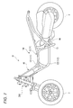
- FIG. 7 shows a body frame 10 of the lean vehicle 1 according to the present embodiment.
- the vehicle body frame 10 includes a vehicle-side monolithic body 100 and a link-side monolithic body 200.
- FIG. 8 is a perspective view showing the vehicle-side monolithic body 100.
- FIG. 9 is a sectional view of the vehicle-side monolithic body 100.
- a black-out area indicates a welded portion.
- the vehicle-body-side monolithic body 100 includes a right frame 11 extending in the front-rear direction and a left frame 12 extending in the front-rear direction.
- the left frame 12 is provided on the left side of the right frame 11.
- the right frame 11 includes an upper right frame 111 and a lower right frame 112 provided below the upper right frame 111.
- the left frame 12 includes an upper left frame 121 and a lower left frame 122 provided below the upper left frame 121.
- the vehicle-side monolithic body 100 has a power unit support portion 13.
- the power unit support portion 13 supports the power unit 96 so as to be able to swing with respect to the vehicle body side monolithic body 100.
- the power unit support 13 is welded to the lower right frame 112 and the lower left frame 122.
- the coupling portion 40 includes a right plate portion 41 (see FIG. 9), a left plate portion 42, an upper plate portion 43 (see FIG. 9), a lower plate portion 44, and a front plate portion 45.
- These right plate portion 41, left plate portion 42, upper plate portion 43, lower plate portion 44, and front plate portion 45 are plate-shaped parts.
- Right plate portion 41 is welded to upper right frame 111 and lower right frame 112.
- the left plate portion 42 is welded to the upper left frame 121 and the lower left frame 122.
- the upper plate part 43 is welded to the upper right frame 111 and the upper left frame 121.
- the lower plate portion 44 is welded to the lower right frame 112 and the lower left frame 122.
- the front plate 45 is welded to the front end of the upper right frame 111, the front end of the lower right frame 112, the front end of the upper left frame 121, and the front end of the lower left frame 122.
- the normal direction of the front plate portion 45 is parallel to the lower intermediate leaning axis LDI.
- three upper bolt through holes 46 through which three upper bolts 97 are respectively provided are provided in the upper portion of the front plate portion 45.
- three lower bolt through holes 47 through which three lower bolts 98 are respectively passed are provided in the lower portion of the front plate portion 45.
- An intermediate bolt through hole 48 (see FIG. 9) through which the intermediate bolt 99 is inserted is provided at the center of the front plate portion 45.
- the vehicle-body-side monolithic body 100 includes a bolt support 49 welded to the front plate 45 and the upper plate 43.
- the bolt support 49 extends in the front-rear direction.
- the front portion of the bolt support portion 49 is welded to the front plate portion 45, and the rear portion of the bolt support portion 49 is welded to the upper plate portion 43.
- the bolt supporting portion 49 is provided with an intermediate bolt through hole 48 into which the intermediate bolt 99 is inserted. That is, the bolt support portion 49 is welded to the vehicle body-side monolithic body 100 at two locations along the axial direction of the intermediate bolt 99.
- FIG. 10 is a perspective view showing the link-side monolithic body 200.
- FIG. 11 is a sectional view of the link-side monolithic body 200.
- the main pipe portion 21 supports the steering shaft 62 so as to be rotatable around the intermediate steering axis SI.
- the upper boss portion 22 supports an intermediate portion of the upper cross member 51 so as to be rotatable around an upper intermediate leaning axis LUI.
- the lower boss portion 23 supports an intermediate portion of the lower cross member 52 so as to be rotatable around a lower intermediate leaning axis LDI.
- the upper boss portion 22 and the lower boss portion 23 are welded to the main pipe portion 21.
- the upper bolt mounting portion 24 and the lower bolt mounting portion 25 are monolithically connected to form an integral body.
- the upper bolt mounting part 24 is a metal plate bent in a U-shape.
- the upper bolt mounting part 24 is welded to the rear part of the main pipe part 21.
- the upper bolt mounting portion 24 is provided with three bolt mounting holes 39 through which the upper bolts 97 are respectively passed.
- the upper bolt mounting portion 24 is provided at a height substantially equal to that of the upper boss portion 22 in the direction of the intermediate steering axis SI.
- the lower bolt mounting portion 25 includes a pipe portion 36 and a plate-shaped portion 37 provided at a rear end of the pipe portion.
- the front end of the pipe 36 is welded to the rear of the main pipe 21.
- the plate-like portion 37 is provided with three bolt mounting holes 38 through which the lower bolts 98 pass.
- the lower bolt mounting portion 25 is provided at a height similar to that of the lower boss portion 23 in the direction of the intermediate steering axis SI.
- the lower boss 23 includes a lower front boss 231 that rotatably supports the lower front cross element 521 and a lower rear boss 232 that rotatably supports the lower rear cross element 522.
- the upper boss portion 22 is provided so as to protrude forward from a front portion of the main pipe portion 21.
- the upper boss 22 is provided with an upper hole 32 into which the upper shaft member 31 is inserted.
- the upper middle leaning axis LUI which is the rotation axis of the upper cross member 51, passes through the upper hole 32.
- the upper shaft member 31 protrudes forward from the upper hole 32 and is fixed to an inner ring of an upper intermediate leaning bearing portion 51 a provided on the upper cross member 51.
- the central axis of the upper shaft member 31 matches the upper middle leaning axis LUI.
- the lower boss 23 has a lower front boss 231 and a lower rear boss 232.
- the lower front boss portion 231 is provided so as to protrude forward from a front portion of the main pipe portion 21.
- the lower front boss 231 is provided with a lower front hole 35 into which the lower front shaft member 33 is inserted.
- the lower intermediate leaning axis LDI which is the rotation axis of the lower cross member 52, passes through the lower front hole 35.
- the lower front shaft member 33 protrudes forward from the lower front hole 35 and is fixed to an inner ring of a lower intermediate leaning bearing portion 52 a provided on the lower front cross element 521.
- the central axis of the lower front shaft member 33 coincides with the lower intermediate leaning axis LDI.
- the lower rear boss portion 232 is provided so as to protrude rearward from the rear portion of the main pipe portion 21.
- the lower rear boss portion 232 is provided with a lower rear hole portion 34 into which the intermediate bolt 99 is inserted.
- a lower intermediate leaning axis LDI which is a rotation axis of the lower cross member 52, passes through the lower rear hole portion.
- the intermediate bolt 99 projects rearward from the lower rear hole portion 34 and is fixed to the inner ring of the lower rear leaning bearing portion 52b provided in the lower rear cross element 522.
- the central axis of the intermediate bolt 99 coincides with the lower intermediate leaning axis LDI.
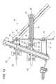
- FIG. 12 is a cross-sectional view showing a joint portion between the vehicle body side monolithic body 100 and the link side monolithic body 200. As shown in FIG. 12, the vehicle body side monolithic body 100 and the link side monolithic body 200 are connected by an upper bolt 97, a lower bolt 98, and an intermediate bolt 99.
- the upper bolt 97 penetrates the front plate portion 45 of the vehicle-side monolithic body 100 and the upper bolt mounting portion 24 of the link-side monolithic body 200.
- the lower bolt 98 passes through the front plate portion 45 of the vehicle-side monolithic body 100 and the lower bolt mounting portion 25 of the link-side monolithic body 200.
- the upper bolt 97 has a central upper intermediate bolt 97a located on the lower intermediate leaning axis LDI when viewed from above, and a rightward side from the lower intermediate leaning axis LDI when viewed from above. And an upper left bolt 97c provided to the left of the lower intermediate leaning axis LDI when viewed from above.
- the lower bolt 98 includes a central lower intermediate bolt 98a located on the lower intermediate leaning axis LDI when viewed from above, and a lower right bolt 98b provided to the right of the lower intermediate leaning axis LDI when viewed from above. And a lower left bolt 98c provided to the left of the lower intermediate leaning axis LDI when viewed from above.
- the intermediate bolt 99 includes a lower rear hole portion 34 provided in the lower rear boss portion 232 of the link side monolithic body 200, an inner ring of the lower rear leaning bearing portion 52 b of the lower rear cross element 522, and a bolt of the vehicle body side monolithic body 100.
- the support portion 49 penetrates.
- the intermediate bolt 99 is a stud bolt.
- the front part of the intermediate bolt 99 is screwed into the lower rear hole part 34.
- the rear portion of the intermediate bolt 99 projects rearward from the bolt support portion 49.
- a nut 101 is screwed to the rear end of the intermediate bolt 99 projecting rearward from the bolt support 49.
- the intermediate bolt 99 is provided on the lower intermediate leaning axis LDI when viewed from above.
- the link side monolithic body 200 that rotatably supports the link mechanism 5 and the steering shaft 62 is fastened to the vehicle body side monolithic body 100 with the bolts 97 to 99, so that welding is performed. At this time, deformation of the upper boss portion 22 and the lower boss portion 23 is avoided.
- a member and B member are connected monolithically to form a monolithic body (A member and B member are connected monolithically so so as to make one body)” is a metallic A member.
- a mode in which the member and the metal B member are connected so as to be continuous by metal is referred to as being monolithically joined and integrated.
- a member in which the A member and the B member are formed by casting and are connected to each other is also referred to as being monolithically joined to be an integral body.
- a member in which the A member and the B member are connected by a fastening means such as a bolt has a gap between the A member and the B member. I do not call it.
- a structure in which the A member and the B member are monolithically integrated tends to have higher strength than a structure in which the A member and the B member are connected by fastening means.
- the structure on the vehicle body side is integrated as a vehicle-side monolithic body 100 to increase the strength
- the structure supporting the link mechanism 5 and the steering shaft 62 is integrated as a link-side monolithic body 200 to increase the strength. Is increasing. By means of connecting these groups of structures having increased strength with bolts, the strength of the entire vehicle is increased while ensuring ease of assembly.
- the body-side monolithic body 100 can be designed in any shape as long as the right frame 11 and the left frame 12 of the body frame 10 are configured to be monolithically combined to form an integral body. Therefore, for example, the present invention is advantageous when a new vehicle is provided by using the newly designed link mechanism 5 and the body frame 10 of the existing lean vehicle 1. Unlike the present invention, when the body frame 10 is welded to the main pipe portion 21, it is necessary to change the design of the body frame 10 of the existing lean vehicle 1 so as to match the newly designed link mechanism 5. However, according to the present invention, if the vehicle-body-side monolithic body 100 is formed on the body frame 10 of the existing lean vehicle 1 and the link-side monolithic body 200 suitable for the new link mechanism 5 is designed, it is relatively simple. Vehicle can be provided.
- the lower cross member 52 has a lower rear cross element 522 located behind the link-side monolithic body 200,
- the lower boss portion 23 has a lower rear hole portion 34 in which a lower rear shaft member that supports the lower rear cross element 522 so as to be rotatable around a lower intermediate leaning axis LDI is supported.
- the intermediate bolt 99 is supported by the lower rear hole 34.
- the intermediate bolt 99 can be provided at a position where the intermediate bolt 99 does not interfere with the lower cross member 52 and does not increase the body frame 10 in the vertical direction.
- the intermediate bolt 99 extends from the lower rear hole portion 34, passes through the lower rear cross element 522, and is fastened to the vehicle body side monolithic body 100.
- the intermediate bolt 99 can be provided at a position where the intermediate bolt 99 does not interfere with the lower cross member 52 and does not increase the body frame 10 in the vertical direction.
- the intermediate bolt 99 extends along the lower intermediate leaning axis LDI.
- the intermediate bolt 99 can be provided at a position where the intermediate bolt 99 does not interfere with the lower cross member 52 and does not increase the body frame 10 in the vertical direction.
- a bolt support portion 49 (an example of a first fastening portion) into which the intermediate bolt 99 is inserted is monolithically coupled to the vehicle body-side monolithic body 100 to form an integral body.
- the bolt support portions 49 are fixed to the body frame 10 at a plurality of positions in the axial direction of the intermediate bolt 99.
- a front plate portion 45 (an example of a plate-shaped portion) whose normal direction is parallel to the lower intermediate leaning axis LDI is monolithically coupled to the vehicle body-side monolithic body 100 to be integrated.
- the front plate portion 45 since the front plate portion 45 is in surface contact with the link-side monolithic body 200, the front plate portion 45 can easily receive a large force. Further, since the planar front plate portion 45 comes into contact with the link-side monolithic body 200, it can be connected to the link-side monolithic body 200 with high dimensional accuracy.
- the lean vehicle 1 includes: An upper bolt 97 provided above the lower cross member 52 and provided on the right and left sides of the lower middle leaning axis LDI, and a right side of the lower cross member 52 provided below the lower cross member LDI. And at least one of a lower bolt 98 provided on the left side.
- the link side monolithic body 200 and the vehicle body side monolithic body 100 are connected by at least one of the upper bolt 97 and the lower bolt 98 (both in the above embodiment) and the intermediate bolt 99.
- the intermediate bolt 99 Have been. Therefore, for example, when both the right front wheel 2 and the left front wheel 3 ride on a step, when a force is applied to the link-side monolithic body 200 such that the lower part is pushed backward and the upper part is pushed forward, The force can be received by at least one of the bolt 97 and the lower bolt 98 and the intermediate bolt 99.
- An upper cross member 51 is provided in front of the link-side monolithic body 200,
- An upper bolt 97 is provided behind the link-side monolithic body 200 at a position overlapping the upper cross member 51 in a front view of the lean vehicle 1.
- the upper front cross element can effectively receive the force pushing the link-side monolithic body 200 backward by the upper bolt 97. Further, since the upper bolt 97 can be disposed using the space on the opposite side of the upper front cross element with the main pipe portion 21 of the link-side monolithic body 200 interposed therebetween, the vehicle is prevented from being enlarged.
- the right frame 11 An upper right frame 111 extending in the front-rear direction, It has a lower right frame 112 extending in the front-rear direction and located below the upper right frame 111,
- the left frame 12 An upper left frame 121 extending in the front-rear direction, It has a lower left frame 122 extending in the front-rear direction and located below the upper left frame 121,
- the upper right frame 111, the lower right frame 112, the upper left frame 121, and the lower left frame 122 are monolithically connected to form an integral body.
- the upper right frame 111, the lower right frame 112, the upper left frame 121, and the lower left frame 122 are monolithically combined to form a single body-side monolithic body 100. For this reason, the strength of the vehicle-side monolithic body 100 is further increased, and the force input from the link-side monolithic body 200 can be more easily received.
- the upper cross member 51 is located forward of the main pipe portion 21,
- the lower cross member 52 has a lower front cross element 521 located forward of the main pipe portion 21 and a lower rear cross element 522 located rearward of the link support section.
- An upper boss portion 22 that supports an upper shaft member 31 that rotatably supports the upper cross member 51 around an upper intermediate leaning axis LUI;
- a lower front boss 231 supporting a lower front shaft member 33 that rotatably supports the lower front cross element 521 around a lower intermediate leaning axis LDI;
- a lower rear boss portion 232 supporting a lower rear shaft member rotatably supporting the lower rear cross element 522 about a lower intermediate leaning axis LDI is monolithically coupled to the link side monolithic body 200 to be an integral body. .
- the lower cross member 52 includes the lower front cross element 521 and the lower rear cross element 522, so that the rigidity of the lower cross member 52 is increased.
- the upper cross member 51 is provided forward of the main pipe portion 21, and the lower cross member 52 is provided with a lower front cross element 521 provided forward of the main pipe portion 21 and the main pipe portion 21.
- the configuration has been described in which the lower rear cross element 522 provided further rearward, and the intermediate bolt 99 penetrates the lower rear cross element 522 to fasten the link side monolithic body and the vehicle body side monolithic body.
- the present invention is not limited to this structure.
- the upper cross member has an upper front cross element provided in front of the main pipe portion 21 and an upper rear cross element provided in back of the main pipe portion 21, and the lower cross member 52 is It may be provided in front.
- the intermediate bolt penetrates the upper rear cross element to fasten the link side monolithic body and the vehicle body side monolithic body.
- the upper cross member includes an upper front cross element provided forward of the main pipe portion 21 and an upper rear cross element provided rearward of the main pipe portion 21, and the lower cross member 52 includes A lower front cross element 521 provided forward of the section 21 and a lower rear cross element 522 provided rearward of the main pipe section 21 may be provided.
- a structure in which the link side monolithic body and the vehicle body side monolithic body are fastened by at least one of the upper intermediate bolt penetrating the upper rear cross element and the lower intermediate bolt penetrating the lower rear cross element 522 may be employed. it can.
- the lean vehicle 1 includes two front wheels 2 and 3 and one rear wheel 4. However, a plurality of rear wheels may be provided.
- the rear wheel 4 is arranged behind the left front wheel 3 and the right front wheel 2 in the front-rear direction of the body frame 10.
- at least one wheel may be provided rearward of the left front wheel 3 and the right front wheel 2 in the front-rear direction of the body frame 10.
- the driving force from the power source of the power unit 96 can be supplied to the left front wheel 3, the right front wheel 2, and at least one of the wheels.
- the handlebar 61 is formed of a single member extending in the left-right direction of the body frame.
- the handlebar 61 is provided with a left handle portion operated by the driver's left hand and a right handle operated by the driver's right hand.
- a configuration in which the units are provided separately can be adopted.
- a configuration including a cross member other than the upper cross member 51 and the lower cross member 52 can be adopted.
- the “upper cross member” and the “lower cross member” are simply named based on the relative vertical relationship.
- the upper cross member does not mean the uppermost cross member in the link mechanism 5.
- the upper cross member means a cross member located above another cross member.
- the lower cross member does not mean the lowest cross member in the link mechanism 5.
- the lower cross member means a cross member located below another cross member.
- each of the upper front cross member, the lower front cross member, and the lower rear cross member has a right end supporting the upper part of the right side part, a left end supporting the upper part of the left side part, and a link side.
- An example is shown in which a single-piece member integrally provided with an intermediate portion supported by a monolithic body is shown. The present invention is not limited to this.
- At least one of the upper front cross member, the lower front cross member, and the lower rear cross member is supported by the right end supporting the upper part of the right side part, the left end supporting the upper part of the left side part, and the link side monolithic body.
- the expression “displaceably arranged with respect to the body frame 10” refers to not only a part or a member directly fixed to the body frame 10 but also the body frame 10. Includes those that are fixed to fixed vehicle parts (fuel tanks, brackets, power units, etc.).
- fixing includes fixing via a vibration isolating member or the like.
- a front two-wheel lean vehicle that can be assembled without welding a link support portion to a vehicle body frame.
Landscapes
- Engineering & Computer Science (AREA)
- Mechanical Engineering (AREA)
- Automatic Cycles, And Cycles In General (AREA)
- Vehicle Body Suspensions (AREA)
Abstract
L'invention concerne un véhicule inclinable (1) comprenant : un corps monolithique côté véhicule (100) qui est constitué d'un cadre droit (11) et d'un cadre gauche (12) assemblés de façon monolithique en un seul corps et est pourvu d'une partie de support d'unité d'alimentation (13) ; et un corps monolithique côté liaison (200). Le corps monolithique côté liaison (200) est constitué par un bossage supérieur (22) pour supporter un élément transversal supérieur (51) d'un mécanisme de liaison (5), un bossage inférieur (23) pour supporter un élément transversal inférieur (52), et un tuyau principal (21) pour supporter de manière rotative un arbre de direction (62), le bossage supérieur, le bossage inférieur et le tuyau principal étant assemblés de façon monolithique en un seul corps. Le corps monolithique côté liaison (200) est fixé au corps monolithique côté véhicule (100) par des boulons (97, 98, 99).
Priority Applications (2)
| Application Number | Priority Date | Filing Date | Title |
|---|---|---|---|
| EP19858256.1A EP3756987B1 (fr) | 2018-09-07 | 2019-08-30 | Véhicule inclinable |
| ES19858256T ES2915590T3 (es) | 2018-09-07 | 2019-08-30 | Vehículo inclinable |
Applications Claiming Priority (2)
| Application Number | Priority Date | Filing Date | Title |
|---|---|---|---|
| JP2018167913 | 2018-09-07 | ||
| JP2018-167913 | 2018-09-07 |
Publications (1)
| Publication Number | Publication Date |
|---|---|
| WO2020050157A1 true WO2020050157A1 (fr) | 2020-03-12 |
Family
ID=69722317
Family Applications (1)
| Application Number | Title | Priority Date | Filing Date |
|---|---|---|---|
| PCT/JP2019/034057 Ceased WO2020050157A1 (fr) | 2018-09-07 | 2019-08-30 | Véhicule inclinable |
Country Status (4)
| Country | Link |
|---|---|
| EP (1) | EP3756987B1 (fr) |
| ES (1) | ES2915590T3 (fr) |
| TW (1) | TWI714242B (fr) |
| WO (1) | WO2020050157A1 (fr) |
Cited By (2)
| Publication number | Priority date | Publication date | Assignee | Title |
|---|---|---|---|---|
| EP4159606A1 (fr) | 2021-09-30 | 2023-04-05 | Yamaha Hatsudoki Kabushiki Kaisha | Véhicule inclinable |
| EP4667338A1 (fr) * | 2024-06-17 | 2025-12-24 | Kawasaki Motors, Ltd. | Véhicule inclinable |
Families Citing this family (2)
| Publication number | Priority date | Publication date | Assignee | Title |
|---|---|---|---|---|
| CN114194289A (zh) * | 2020-09-17 | 2022-03-18 | 深圳市皓颢智能科技有限公司 | 一种双轮联动机构 |
| TWI772115B (zh) * | 2021-07-20 | 2022-07-21 | 光陽工業股份有限公司 | 可傾斜車輛及其組裝方法 |
Citations (4)
| Publication number | Priority date | Publication date | Assignee | Title |
|---|---|---|---|---|
| WO2014007819A2 (fr) | 2012-07-05 | 2014-01-09 | Empire Technology Development Llc | Feuille panneau tactile dilatant déformable |
| WO2014098198A1 (fr) | 2012-12-19 | 2014-06-26 | ヤマハ発動機株式会社 | Véhicule |
| JP2018095147A (ja) * | 2016-12-15 | 2018-06-21 | ヤマハ発動機株式会社 | 車両 |
| JP2018167913A (ja) | 2017-03-29 | 2018-11-01 | 株式会社日立製作所 | エレベータ |
Family Cites Families (8)
| Publication number | Priority date | Publication date | Assignee | Title |
|---|---|---|---|---|
| JPS5954385U (ja) * | 1982-10-04 | 1984-04-10 | 本田技研工業株式会社 | 自動二輪車等の車体フレ−ム |
| CN1990339A (zh) * | 2005-12-30 | 2007-07-04 | 雅马哈发动机株式会社 | 机车的车架结构 |
| JP6495887B2 (ja) * | 2013-03-15 | 2019-04-03 | ポラリス インダストリーズ インコーポレーテッド | 2輪車両 |
| EP3002199B1 (fr) * | 2013-07-01 | 2018-01-10 | Yamaha Hatsudoki Kabushiki Kaisha | Véhicule |
| ITUB20152605A1 (it) * | 2015-07-29 | 2017-01-29 | Piaggio & C Spa | Avantreno di motoveicolo tiltante e relativo motoveicolo |
| JP6134362B2 (ja) * | 2015-09-18 | 2017-05-24 | 本田技研工業株式会社 | 車両のサスペンションロック機構 |
| JP2017065529A (ja) * | 2015-09-30 | 2017-04-06 | ヤマハ発動機株式会社 | 車両 |
| WO2017208992A1 (fr) * | 2016-05-30 | 2017-12-07 | ヤマハ発動機株式会社 | Véhicule |
-
2019
- 2019-08-30 EP EP19858256.1A patent/EP3756987B1/fr active Active
- 2019-08-30 ES ES19858256T patent/ES2915590T3/es active Active
- 2019-08-30 WO PCT/JP2019/034057 patent/WO2020050157A1/fr not_active Ceased
- 2019-09-03 TW TW108131614A patent/TWI714242B/zh active
Patent Citations (4)
| Publication number | Priority date | Publication date | Assignee | Title |
|---|---|---|---|---|
| WO2014007819A2 (fr) | 2012-07-05 | 2014-01-09 | Empire Technology Development Llc | Feuille panneau tactile dilatant déformable |
| WO2014098198A1 (fr) | 2012-12-19 | 2014-06-26 | ヤマハ発動機株式会社 | Véhicule |
| JP2018095147A (ja) * | 2016-12-15 | 2018-06-21 | ヤマハ発動機株式会社 | 車両 |
| JP2018167913A (ja) | 2017-03-29 | 2018-11-01 | 株式会社日立製作所 | エレベータ |
Non-Patent Citations (1)
| Title |
|---|
| See also references of EP3756987A4 |
Cited By (2)
| Publication number | Priority date | Publication date | Assignee | Title |
|---|---|---|---|---|
| EP4159606A1 (fr) | 2021-09-30 | 2023-04-05 | Yamaha Hatsudoki Kabushiki Kaisha | Véhicule inclinable |
| EP4667338A1 (fr) * | 2024-06-17 | 2025-12-24 | Kawasaki Motors, Ltd. | Véhicule inclinable |
Also Published As
| Publication number | Publication date |
|---|---|
| EP3756987B1 (fr) | 2022-03-30 |
| EP3756987A4 (fr) | 2021-04-07 |
| ES2915590T3 (es) | 2022-06-23 |
| TWI714242B (zh) | 2020-12-21 |
| TW202015957A (zh) | 2020-05-01 |
| EP3756987A1 (fr) | 2020-12-30 |
Similar Documents
| Publication | Publication Date | Title |
|---|---|---|
| US9475535B2 (en) | Vehicle | |
| US9452806B2 (en) | Vehicle | |
| US10994796B2 (en) | Leaning vehicle | |
| US20160114850A1 (en) | Vehicle | |
| US10167043B2 (en) | Vehicle | |
| WO2020050157A1 (fr) | Véhicule inclinable | |
| JP2005104296A (ja) | 車両のアンチロールバー装置取付構造 | |
| JP5941601B1 (ja) | 車両 | |
| JP2017094906A (ja) | 車両 | |
| JP2018144698A (ja) | 車両 | |
| EP3372479B1 (fr) | Véhicule à inclinaison | |
| JP2018144697A (ja) | 車両 | |
| JP2017065526A (ja) | 車両 | |
| JP4774976B2 (ja) | 車両の後部車体構造 | |
| JP6728019B2 (ja) | 車両 | |
| EP3613660B1 (fr) | Véhicule à inclinaison | |
| JP2009179285A (ja) | 自動二輪車のフレーム構造 | |
| US11135886B2 (en) | Vehicle | |
| JP6270073B2 (ja) | 鞍乗り型車両のスイングアーム | |
| CN105377678B (zh) | 车辆 | |
| EP3620361B1 (fr) | Véhicule à inclinaison | |
| JP2008068754A (ja) | トーションビーム式サスペンション装置 | |
| JP2017222301A (ja) | 車両 | |
| JP2017065668A (ja) | 車両 | |
| JP2024006428A (ja) | 鞍乗型車両 |
Legal Events
| Date | Code | Title | Description |
|---|---|---|---|
| 121 | Ep: the epo has been informed by wipo that ep was designated in this application |
Ref document number: 19858256 Country of ref document: EP Kind code of ref document: A1 |
|
| ENP | Entry into the national phase |
Ref document number: 2019858256 Country of ref document: EP Effective date: 20200923 |
|
| NENP | Non-entry into the national phase |
Ref country code: DE |
|
| NENP | Non-entry into the national phase |
Ref country code: JP |