WO2020054051A1 - 鋼管の製造方法及びプレス金型 - Google Patents
鋼管の製造方法及びプレス金型 Download PDFInfo
- Publication number
- WO2020054051A1 WO2020054051A1 PCT/JP2018/034145 JP2018034145W WO2020054051A1 WO 2020054051 A1 WO2020054051 A1 WO 2020054051A1 JP 2018034145 W JP2018034145 W JP 2018034145W WO 2020054051 A1 WO2020054051 A1 WO 2020054051A1
- Authority
- WO
- WIPO (PCT)
- Prior art keywords
- steel pipe
- molded body
- mold
- press
- range
- Prior art date
- Legal status (The legal status is an assumption and is not a legal conclusion. Google has not performed a legal analysis and makes no representation as to the accuracy of the status listed.)
- Ceased
Links
Images






Classifications
-
- B—PERFORMING OPERATIONS; TRANSPORTING
- B21—MECHANICAL METAL-WORKING WITHOUT ESSENTIALLY REMOVING MATERIAL; PUNCHING METAL
- B21C—MANUFACTURE OF METAL SHEETS, WIRE, RODS, TUBES, PROFILES OR LIKE SEMI-MANUFACTURED PRODUCTS OTHERWISE THAN BY ROLLING; AUXILIARY OPERATIONS USED IN CONNECTION WITH METAL-WORKING WITHOUT ESSENTIALLY REMOVING MATERIAL
- B21C37/00—Manufacture of metal sheets, rods, wire, tubes, profiles or like semi-manufactured products, not otherwise provided for; Manufacture of tubes of special shape
- B21C37/06—Manufacture of metal sheets, rods, wire, tubes, profiles or like semi-manufactured products, not otherwise provided for; Manufacture of tubes of special shape of tubes or metal hoses; Combined procedures for making tubes, e.g. for making multi-wall tubes
- B21C37/08—Making tubes with welded or soldered seams
- B21C37/0815—Making tubes with welded or soldered seams without continuous longitudinal movement of the sheet during the bending operation
-
- B—PERFORMING OPERATIONS; TRANSPORTING
- B21—MECHANICAL METAL-WORKING WITHOUT ESSENTIALLY REMOVING MATERIAL; PUNCHING METAL
- B21C—MANUFACTURE OF METAL SHEETS, WIRE, RODS, TUBES, PROFILES OR LIKE SEMI-MANUFACTURED PRODUCTS OTHERWISE THAN BY ROLLING; AUXILIARY OPERATIONS USED IN CONNECTION WITH METAL-WORKING WITHOUT ESSENTIALLY REMOVING MATERIAL
- B21C37/00—Manufacture of metal sheets, rods, wire, tubes, profiles or like semi-manufactured products, not otherwise provided for; Manufacture of tubes of special shape
- B21C37/06—Manufacture of metal sheets, rods, wire, tubes, profiles or like semi-manufactured products, not otherwise provided for; Manufacture of tubes of special shape of tubes or metal hoses; Combined procedures for making tubes, e.g. for making multi-wall tubes
- B21C37/08—Making tubes with welded or soldered seams
-
- B—PERFORMING OPERATIONS; TRANSPORTING
- B21—MECHANICAL METAL-WORKING WITHOUT ESSENTIALLY REMOVING MATERIAL; PUNCHING METAL
- B21D—WORKING OR PROCESSING OF SHEET METAL OR METAL TUBES, RODS OR PROFILES WITHOUT ESSENTIALLY REMOVING MATERIAL; PUNCHING METAL
- B21D3/00—Straightening or restoring form of metal rods, metal tubes, metal profiles, or specific articles made therefrom, whether or not in combination with sheet metal parts
- B21D3/16—Straightening or restoring form of metal rods, metal tubes, metal profiles, or specific articles made therefrom, whether or not in combination with sheet metal parts of specific articles made from metal rods, tubes, or profiles, e.g. crankshafts, by specially adapted methods or means
-
- B—PERFORMING OPERATIONS; TRANSPORTING
- B21—MECHANICAL METAL-WORKING WITHOUT ESSENTIALLY REMOVING MATERIAL; PUNCHING METAL
- B21D—WORKING OR PROCESSING OF SHEET METAL OR METAL TUBES, RODS OR PROFILES WITHOUT ESSENTIALLY REMOVING MATERIAL; PUNCHING METAL
- B21D5/00—Bending sheet metal along straight lines, e.g. to form simple curves
- B21D5/01—Bending sheet metal along straight lines, e.g. to form simple curves between rams and anvils or abutments
-
- B—PERFORMING OPERATIONS; TRANSPORTING
- B21—MECHANICAL METAL-WORKING WITHOUT ESSENTIALLY REMOVING MATERIAL; PUNCHING METAL
- B21D—WORKING OR PROCESSING OF SHEET METAL OR METAL TUBES, RODS OR PROFILES WITHOUT ESSENTIALLY REMOVING MATERIAL; PUNCHING METAL
- B21D5/00—Bending sheet metal along straight lines, e.g. to form simple curves
- B21D5/01—Bending sheet metal along straight lines, e.g. to form simple curves between rams and anvils or abutments
- B21D5/015—Bending sheet metal along straight lines, e.g. to form simple curves between rams and anvils or abutments for making tubes
Definitions
- the present invention relates to a method for manufacturing a steel pipe and a press die used in the method for manufacturing the steel pipe.
- UOE forming technique is an open pipe, which is a pipe having a seam gap between sheet width ends facing each other in the circumferential direction, by first pressing a steel sheet into a U-shape and then pressing it into an O-shape.
- the seam gap of this open pipe is butt-joined by welding to form a steel pipe, and then the steel pipe is expanded to further increase its diameter.
- a high press force is required in a process of forming an open pipe by pressing a steel sheet into a U-shape or an O-shape, so a large-scale press machine must be used. There is no situation.
- the force required to close the seam gap portion by abutting the facing plate width ends increases, and the equipment for closing the seam gap portion increases in size.
- the force to open the seam gap portion due to springback acts on the welded portion after welding the seam gap portion where the opening amount is too large, welding defects are likely to occur, and if the force is too large, welding will be performed. The part breaks.
- Patent Documents 1 to 4 disclose techniques for reducing the opening amount of the seam gap portion of the open pipe after press bending.
- Patent Literature 1 discloses a technique for reducing the width of a punch support and reducing the opening amount of a seam gap portion of an open pipe by freely rotating a connecting portion between a punch tip and a punch support. ing.
- Patent Literature 2 an interval maintaining means for restricting the movement of the plate material in a direction orthogonal to the movement direction of the punch is provided, and a large pressure is applied in the final bending process without the plate width end contacting the punch support.
- Patent Literature 3 discloses a technique for measuring a gap between a plate width end portion and a punch support after a final rolling-down process, and reducing the gap as much as possible to reduce the opening amount of a seam gap portion of an open pipe. I have. Further, in Patent Literature 4, the amount of reduction by the punch in the final step is determined based on the time when the interval between the sheet width ends becomes a predetermined value at the time of the reduction in the final bending step. A technique for reducing the opening amount of the seam gap portion of the open pipe regardless of the difference in shape caused by the above has been disclosed.
- Patent Documents 5 to 9 disclose techniques for further processing the open pipe after press bending to reduce the opening amount of the seam gap.
- Patent Literature 5 discloses a technique in which hot roll forming is performed on a steel pipe after press bending to form the pipe with a small load.
- Patent Literature 6 discloses that a strain detector that can detect inclination or distortion of a pressing member mounted on a slide is provided, and that the pressing member can be tilted in accordance with the detection of the inclination or distortion of the distortion detector.
- Patent Document 7 discloses that at least one bending step acting on the left and right inner surfaces of a plate material with respect to a center defined by a longitudinal axis of an upper tool entering a plate material to be gradually formed, compared with other bending steps. Forming a slit tube with a non-circular preform by means of a slight shaping and then acting on the non-circular preform from the outside in each case in the pre-slightly shaped area on both sides of the center.
- Patent Document 8 discloses that a molded body having a flat portion between at least two pipe curved portions is subjected to plastic deformation only at least at one flat portion to obtain a predetermined curvature.
- Patent Document 9 discloses that an open pipe is formed by rolling down a formed body having a lightly worked portion having a very small curvature compared to other regions or an unprocessed portion having no bending process.
- a method is disclosed in which a pressing force is applied without restraining a lightly processed portion or an unprocessed portion to form a pipe with a slit portion closed. Also, it is recommended that when pressed, the molded body be held in a mold in a U-shape with the open portion facing upward and supported at the lowermost end of the molded body.
- Patent Documents 10 and 11 disclose techniques for manufacturing a UOE pipe having a product diameter different from the inner diameter of the O-press die and the outer diameter of the product pipe.
- the mold disclosed in Patent Literature 10 has a shape in which the inner surfaces of upper and lower dies have only a part of a horizontally long oval cut out, and the operation of the die is described with reference to FIG. 4A, the O tube is in contact with the entire inner surface of the O press die.
- an arc having a radius larger than the outer diameter of the product is formed on the inner surface, the end surface is ground in advance, and a mold having a sufficiently large gap is used.
- a method is disclosed in which, after compression, the formed pipe is rotated by approximately 90 [°] and O-pressed again to form a circular shape. In the first O-press step at this time, the steel pipe is in close contact with the entire surface of the mold.
- Patent Literature 5 has a problem that the production cost is significantly increased when the consumption of heat energy for heating is included. Further, in the case of using a plate material manufactured through a thermomechanical treatment process to have both strength, toughness, and weldability, this technique may impair its characteristics. In the techniques disclosed in Patent Documents 6 to 8, since a molding material or a non-circular preform is separately molded on each of the right and left sides, a seam gap portion or a slit portion serving as a welded portion when the deformation amount is different on the left and right. In addition, there is a concern that a step (mismatch) may be formed.
- the present invention has been made in view of the above problems, and an object of the present invention is to provide a method for manufacturing a steel pipe and a press die capable of efficiently forming a steel pipe having high roundness.
- a method of manufacturing a steel pipe according to the present invention includes bending a sheet material having both ends in the width direction to be bent three or more times along the width direction. Forming a molded body having a U-shaped cross section by performing processing, and then pressing the molded body to form an open pipe having a seam gap portion in the longitudinal direction thereof, and then forming the seam.
- a lightly processed portion having a smaller curvature than other regions, or an unprocessed portion with no bending process, and the shape of the open pipe is the lowest of the U-shaped cross section.
- the plate width W of the U-shaped cross section inscribed in an arc having the same diameter or substantially the same diameter as the outer diameter of the steel pipe is centered.
- the range of 20% or more is defined as A, and the sum of the ranges of 10% or more of the width W from both ends of the width inscribed in an arc having the same or substantially the same diameter as the outer diameter of the steel pipe is defined as B.
- B is characterized by satisfying Expression (1). 2
- one of the pair of molds may be formed into the other mold so that the U-shaped open side of the molded body faces the other mold.
- the molded body is sandwiched between the pair of molds and the molded body is subjected to press working, the other mold is in a state where the molded body is placed on the other mold.
- the formed body does not contact except for a range in which the outer diameter of the steel pipe is inscribed in an arc having the same diameter or substantially the same diameter, and the press working is completed.
- a part of the other mold has a processing surface that does not come into contact with the open tube, and the one mold has the molded body mounted on the other mold, In the state where the molded body does not contact and press processing is completed, a part of the one mold contacts the open pipe. It is characterized in that it comprises a free working surface.
- a mold having a radius of an arc portion in a range of ⁇ 3.5 [%] with respect to a radius corresponding to an outer radius of the steel pipe is used. Press working.
- a center of a press die used for press working of the molded body and a center in a width direction of the molded body are aligned.
- the feature is that they match.
- the method for manufacturing a steel pipe according to the present invention is characterized in that, in the above invention, the molded body is held in a U-shaped posture with the U-shaped open side facing upward.
- a press die according to the present invention is a press die used in the method of manufacturing a steel pipe of the above invention, wherein the press die comprises a pair of pressing members for sandwiching the molded body,
- the surface of the mold that can come into contact with the molded body has a radius corresponding to the outer radius of the steel pipe ⁇ 3.5 [%] so that the center of the arc is located at the position corresponding to the processing center of each mold.
- the center angle of the arc portion in each mold is 70 degrees or more, and the sum of the angles of the center angles of both molds is less than 360 degrees. It is characterized by the following.
- the press die according to the present invention is characterized in that, in the above invention, the angles of the central angles of the two dies are the same.
- each die is connected to both ends of the arc portion in the arc direction, a straight portion, or a small curvature arc portion having a smaller curvature than the arc portion. It is characterized by having.
- a method of manufacturing a steel pipe according to the present invention is characterized by using the press die of the above invention in the method of manufacturing a steel pipe of the above invention.
- the method for manufacturing a steel pipe and the press die according to the present invention have an effect that a steel pipe having high roundness can be efficiently formed.
- FIG. 1 is an external perspective view of a die, a punch, and the like used for molding a molded body having a U-shaped cross section by a press bend method according to the embodiment.
- FIG. 2 is a diagram showing a procedure for forming a molded body having a U-shaped cross section by a press bend method.
- FIG. 3 is a cross-sectional view of a formed body having a U-shaped cross section.
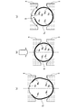
- FIG. 4 is a diagram schematically illustrating a process of forming an open pipe by applying an O-press to the formed body.
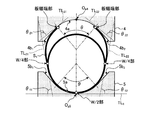
- FIG. 5 is an explanatory diagram of the arc portion, the straight portion, and the central angle of the upper mold and the lower mold.
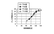
- FIG. 6 is a graph showing the relationship between the opening amount of the seam gap portion of the open pipe and the constraint range together with the press load.
- FIG. 7 is a diagram schematically illustrating a deformation state when an open tube is formed using an upper mold and a lower mold having a constraint range of 0 degrees.
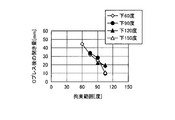
- FIG. 8 is a graph showing the relationship between the constraint range and the roundness of the steel pipe before expansion when the seam gap of the open pipe is closed by welding.
- FIG. 9 is a graph showing the relationship between the restraint range and the press load.
- FIG. 10 is a graph showing the result of the opening amount of the seam gap portion of the open pipe when the individual constraint ranges of the upper mold and the lower mold are changed.
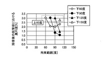
- FIG. 11 is a graph showing the results of roundness of a steel pipe before expansion, which is formed by closing the seam gap portion of the open pipe by welding when the individual constraint ranges of the upper die and the lower die are changed. It is.
- FIG. 12 is a graph showing the results of the press load when the individual constraint ranges of the upper mold and the lower mold are changed.
- FIG. 13 shows the opening of the seam gap when the length of the lightly processed portion or the unprocessed portion of the molded body after press bend is changed while the constraint range of the upper mold and the constraint range of the lower mold are the same. 4 is a graph showing the results of the amounts.
- FIG. 12 is a graph showing the results of the press load when the individual constraint ranges of the upper mold and the lower mold are changed.
- FIG. 13 shows the opening of the seam gap when the length of the lightly processed portion or the unprocessed portion of the molded body after press bend is changed while the constraint range of the upper mold and the constraint range of the lower mold are the same
- FIG. 14 shows a case where the constraint range of the upper mold and the constraint range of the lower mold are the same, and the length of the lightly processed portion or the unprocessed portion of the molded body after press bend is changed. It is a graph which shows the result of roundness.
- FIG. 15 shows the results of the press load when the length of the lightly worked portion or the unprocessed portion of the molded body after press bend is changed while the constraint range of the upper mold and the constraint range of the lower mold are the same. It is a graph.
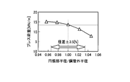
- FIG. 16 is a graph showing the result of the opening amount of the seam gap portion of the open tube when the radius of the arc portion of the upper mold and the lower mold is changed.
- FIG. 17 is a graph showing the results of the press load when the radii of the arc portions of the upper mold and the lower mold are changed.
- FIG. 1 is an external perspective view of a die 1 and a punch 2 used for forming a molded body having a U-shaped cross section by a press bend method according to the present embodiment.
- the die 1 is disposed in the transport path of the plate S formed by the plurality of transport rollers 3 and includes a pair of left and right bar members 1a and 1b that support the plate S at two locations along the plate transport direction. Have been. Further, the distance e between the rod-shaped members 1a and 1b in the plate material transport direction can be changed according to the size of the steel pipe to be finally formed.
- the punch 2 is movable in a direction to approach and separate from the die 1.
- the punch 2 has the same shape as the downwardly projecting punch tip 2 a that presses the plate material S and the back surface (upper end face) of the punch tip 2 a.
- a punch support 2b that supports the punch tip 2a.
- the punch support 2b has an upper end connected to a driving unit (not shown), and can apply a pressing force to the punch tip 2a by the driving unit.
- Figure 2 shows a procedure for molding the molded body S 1 forming a U-shaped cross section by pressing bend method. This procedure is performed on the plate material S that has been subjected to the edge bending in advance from the top to the bottom of the left column of FIG. 2, then from the top to the bottom of the center column of FIG. 2, and finally to the right column of FIG. This specifically shows an example of the case where the bending and the feeding of the plate material S are performed. Arrows attached to the punch 2 and the plate S in FIG. 2 indicate the moving directions of the punch 2 and the plate S at each stage.
- the plate S is subjected to an end bending process.
- the edge bending is performed on the edge of the sheet width, which is relatively hard to bend, as compared with the case where the sheet S is bent using the die 1 and the punch 2.
- the roundness of the steel pipe is an index indicating how close the cross-sectional shape of the steel pipe is to a circle, and the difference between the maximum and the minimum of the variation from the approximate arc over the entire circumference of the steel pipe is expressed by the steel pipe diameter.
- the pipe is circumferentially divided into eight equal parts, twelve equal parts, sixteen equal parts, or twenty-four equal parts, and outer diameters are measured at opposing positions.
- the maximum diameter and the minimum diameter are Dmax and Dmin , respectively, the roundness [%] is defined by ⁇ ( Dmax- Dmin ) / D ⁇ ⁇ 100. The closer the roundness is to zero, the closer the cross-sectional shape of the steel pipe is to a perfect circle.
- the plate material S provided with the end bending portion is placed on the die 1 shown in FIG. 1, and while the plate material S is intermittently fed at a predetermined feed amount, the plate material S is subjected to the procedure shown in FIG. along the width direction it is 3 times or more the bending undergone a is formed into the molded body S 1 forming a U-shaped cross section as a whole.
- Figure 3 is a cross-sectional view of a shaped body S 1 forming a U-shaped cross section.
- a portion of the molded body S 1, W / 4 parts is a part especially apart each W / 4 from the strip width end And an unprocessed portion P in which bending is omitted.
- the unprocessed portion P can be provided by increasing the feed of the plate material S and omitting the pressing by the punch 2.
- a portion of the molded body S 1, in particular about respective from strip width end W / 4 parts of the unprocessed portion P without curvature than the other portion in comparison with a small (other portions, very small A lightly processed portion (with a curvature) may be provided.
- lightly processed portion P may be appropriately read as “lightly processed portion”.
- the lightly processed portion can be provided by reducing the amount of pressing applied by the punch 2 to a value smaller than that of the other portions.
- the shape of the punch 2 shown in FIGS. 1 and 2 is an I-shape in which the width of the punch tip 2a in the sheet conveying direction is the same as the width of the punch support 2b in the sheet conveying direction.
- the shape of the punch 2 is not limited to this.
- a substantially inverted T-shaped punch in which the width of the punch tip 2 a in the plate material transport direction is larger than the width of the punch support 2 b in the plate material transport direction can be used.
- the width of the punch support 2b in the plate material transport direction is the same, the use of the substantially inverted T-shaped punch 2 makes it possible to press the plate S with one pressing as compared with the case of using the I-shaped punch 2. Thus, a larger area can be pressed, and the number of times of pressing can be reduced.
- the upper mold 4 and the lower mold 5 are a pair of molds as shown in FIG. 4 comprising a molded body S 1 using a press mold to O-shape by performing O press pressing, between the plate width end portions which face each other in the circumferential direction is a tubular body having a seam gap G open pipe to form the S 2.
- FIGS. 4 (a) (as U-shaped open side of the molded body S 1 is directed upward) upper mold 4 and the molded body S 1 of the U-shape so that the open side faces, bottom install a molded body S 1 in a mold 5, sandwiching the molded body S 1 between the upper mold 4 and the lower mold 5. Further, when pressing of the molded body S 1 is designed so as to coincide with the processing center of the press die, and a center in the width direction of the molded body S 1. Thereby, on the U-shaped open side of the molded body S1, it is possible to uniformly press the left and right ends of the plate width.
- the surface that may contact the shaped body S 1 of the upper mold 4 and the lower mold 5, the center angle ⁇ a outer diameter and the same diameter or substantially the same diameter of the steel pipe to be molded Are formed, and this area is pressed into a shape inscribed in an arc having the same or substantially the same diameter as the outer diameter of the steel pipe.
- the case where the central angle ⁇ is 360 degrees corresponds to the case where 100% of the plate width is pressed into the inscribed shape.
- the central angle ⁇ of the arc portions 4a and 5a is referred to as a constraint range, and a value obtained by dividing the angle by 360 degrees is a shape inscribed in an arc having the same diameter or substantially the same diameter as the outer diameter of the steel pipe. This is the range to be pressed.
- Arc portion 4a is arc center to a position which coincides with the processing center O p4 of the upper mold 4 is positioned, the arc portion 5a, arc center is located at a position which coincides with the processing center O p5 of the lower die 5 are doing.
- the upper mold 4 has straight portions 4b 1 and 4b 2 connected to both ends of the arc portion 4a in the arc direction, and the lower mold 5 has straight lines connected to both ends of the arc portion 5a in the arc direction. and a section 5b 1, 5b 2.
- the arc portion 4a instead of the straight portion 4b 1, 4b 2, 5b 1 , 5b 2, the arc portion 4a, so as to have a small curvature arc portion curvature is smaller than the 5a Is also good.
- arc portions 4a, the linear portion 4b 1 which led to 5a, 4b 2, 5b 1, 5b 2 or small curvature arc section, processing center It is preferable to be symmetric with respect to Op4 and Op5 , that is, with respect to the center of the arc portions 4a and 5a. Further, it is preferable to perform the press working using a mold having a radius of a circular arc portion within a range of ⁇ 3.5 [%] with respect to a radius corresponding to the outer radius of the steel pipe. The reason will be described later.
- a press die composed of upper mold 4 and the lower die 5 which, the shape of the open pipe S 2, the plate around the bottom of the U-shaped cross section A range of 20% or more of the width W (corresponding to a central angle ⁇ of 70 degrees or more) and a range of 10% or more of the plate width W from the plate width end (corresponding to a central angle of 35 degrees or more). but as a shape inscribed in a circular arc of the outer diameter and the same diameter or substantially the same diameter of the steel tube, the molded body S 1 pressing.
- range open pipe S 2 is inscribed in the mold, the upper mold 4 side and the lower die 5 side, substantially the same
- it is a size. That is, a range of 20% or more of the plate width W centered on the lowermost portion of the U-shaped section inscribed in an arc having the same diameter or substantially the same diameter as the outer diameter of the steel pipe is defined as A, and has the same diameter as the outer diameter of the steel pipe.
- A a range of 20% or more of the plate width W centered on the lowermost portion of the U-shaped section inscribed in an arc having the same diameter or substantially the same diameter as the outer diameter of the steel pipe
- B it is preferable to satisfy Expression (1). 2
- the open pipe S 2 certainly is inscribed in a mold in a predetermined range, in order to obtain a good shape, as shown in FIG. 5, the press working In the U-shaped cross section, the formed body S 1 before being applied has an angle ⁇ between the tangent line TL 1 at the W / 2 portion, which is the center of the plate width, and the tangent lines TL 21 and TL 22 at the W / 4 portion. It is preferable that 11 , 12 be 35 degrees or more and less than 90 degrees.
- the formed body S 1 before being subjected to the press working has angles ⁇ 21 , ⁇ 22 formed by the tangents TL 31 , TL 32 at the plate width end and the tangents TL 21 , TL 22 at the W / 4 part.
- the angle is preferably 35 degrees or more and less than 90 degrees.
- the sum of the angles ⁇ 11 and ⁇ 12 formed by the tangent line TL 1 and the tangent lines TL 21 and TL 22 and the tangent line It is preferable that the sum of the angles ⁇ 21 and ⁇ 22 formed by the tangents TL 21 and TL 22 with the tangents TL 31 and TL 32 are substantially the same.
- the molded body S 1 to the lower mold 5, which is the other die so that one of the upper mold 4 is a mold with U-shaped open side of the molded body S 1 is opposite of the pair of molds the is placed, in the molded body S 1 by sandwiching the molded product S 1 by the upper mold 4 and the lower die 5 Upon performing press working, the upper mold 4 and the lower die 5, as follows It has a good machined surface.
- the lower mold 5 in a state of placing the molded bodies S 1 to the lower mold 5, around the bottom of the U-shaped cross-section, 20% or more in the plate width W (center angle ⁇ is 70 above equivalent) without contact moldings S 1 except for the range of degrees, with the press working is completed, and a working surface not in contact with the open pipe S 2 to a portion of the lower die 5.
- the upper mold 4 is opened with placing the shaped body S 1 to the lower mold 5 does not contact the forming body S 1, in a state where the pressing is completed, a portion of the upper mold 4 and a working surface that does not contact the tube S 2.
- the molded body S 1 is preferably held in a U-posture with its U-shaped open side upwards. This is because, in part, working is easier when press working in this position. As another reason, if the case with its U-shaped open side downward, since the own weight of the molded body S 1 is applied to the plate width end portions of the molded article S 1, or the plate width ends, This is to avoid scratches on the mold, which can be avoided.
- the unprocessed portion P is effectively deformed.
- the bending moment is maximum at a position 90 degrees away from the position to which the pressing force is applied, and decreases as the position moves away from this position. Therefore, in order to cause sufficient plastic deformation in the unprocessed portion P, it is necessary to apply a pressing force to a portion separated by W / 4 ⁇ 0.07 W from the center of the unprocessed portion P toward the edge of the sheet width. preferable.
- the center of the unprocessed portion P is provided at a portion including a position separated by W / 4 from the edge of the plate width, for the following reason. That is, as described above, the pressing force is desirably added at a site distant by W / 4 toward the plate width end portions from the center of the unprocessed portion P, and a molded body S 1 open pipe S 2 in step, the shape of the molded body S 1 changes, also changes the position for adding the contact position changes the pressing force of the upper mold 4 and the molded body S 1.
- the unprocessed portion P if provided in the site containing the position separated by W / 4 from the strip width end in the molded body S 1, part of adding the pressing force is always the plate width end portions of the molded article S 1, The unprocessed portion P is most deformed. In this manner, the unprocessed portion P can be deformed by one pressing without changing the pressing position. Further, the raw portion P, preferably provided from the position i.e. the plate width ends of the molded body S 1 adds a pressing force in the range of W / 4 ⁇ 0.07W.
- the unprocessed portion P from the plate width ends of the molded body S 1 It is preferable to provide a portion including a portion separated by W / 4.
- the relationship between the restraint range and amount of opening of the seam gap G of the open pipe S 2 is a graph showing together with the press load.
- the relationship between the opening amount and the restraining range shown in FIG. 6, and the press load, the both end portions of the open pipe S 2 performs expanded tube straightening by the expansion ratio 1 [%] after welding, the tensile strength 630 [ MPa], an outer diameter of 660.4 [mm], and a thickness of 40.0 [mm] when forming a steel pipe.
- the angles ⁇ 11 and ⁇ 12 formed by the tangents at the W / 4 portion, which is a portion separated by / 4, are 75 degrees, and the angles ⁇ 21 , ⁇ 22 formed by the tangents at the plate width end and the tangents at the W / 4 portion.
- the pressing amount, a distance connecting the W / 2 portion of the open pipe S 2 is rolling reduction in (O press is set to be equal to the diameter of the front pipe expansion, vertical size and diameter before pipe expansion To match). 6, the larger the constraint range, it can be seen that the amount of opening of the seam gap G of the open pipe S 2 becomes small.
- Figure 7 is a diagram schematically showing a modified situation when the constraint range was molded open pipe S 2 with the upper mold 4 and the lower mold 5 of 0 degrees.
- the upper mold 4 is in contact with only the both end portions of the molded article S 1
- the lower die 5 is only the plate width central portion of the molded article S 1
- the arc portions 4a and 5a are arcs having a diameter of 1.16 times the outer diameter of the steel pipe so that they contact each other. As shown in FIG.
- Figure 8 is a graph showing the constrained range, the relationship between the roundness of the steel pipe before pipe expansion when closing the weld seam gap portion G of the open pipe S 2. From FIG. 8, when the constrained range is 60 degrees, the roundness is worse than when the constrained range is 0 degrees, but when the constrained range is increased, the roundness is improved and the constrained range is 70 degrees. It can be seen that the roundness is better in the above case than in the case where the constraint range is 0 degree. It can also be seen that the roundness is best when the constraint range is 100 degrees to 110 degrees.
- FIG. 9 is a graph showing the relationship between the restraint range and the press load. From FIG. 9, it can be seen that the press load increases as the constraint range increases. For that reason, increasing the constraint range, restraint in an amount ranging opening of the seam gap G of the open pipe S 2 becomes small, minute the pressing load increases, the pressing equipment is increased in size, the desired opening amount is obtained It is desirable to reduce the range. For example, the press load, 90 [%] when the individual restraint range of the upper die 4 and the lower mold 5 for restraining the entire periphery of the shaped body S 1 in the upper mold 4 and the lower mold 5 is 180 degrees In order to set the range below, the constraint range may be set to 150 degrees or less.
- Figure 10 is a graph showing the results of the amount of opening of the seam gap G of the open pipe S 2 with changes in individual restraining range of the upper die 4 and the lower mold 5.
- 11, the upper mold 4 and with changes in individual restraining range of the lower die 5, roundness of the steel pipe before pipe expansion molded by closing the seam gap portion G of the open pipe S 2 by welding 7 is a graph showing the results of the above.
- FIG. 12 is a graph showing the result of the press load when the respective constraint ranges of the upper mold 4 and the lower mold 5 are changed.
- FIGS. 10 to 12 are directed to a steel pipe having a tensile strength of 630 [MPa], an outer diameter of 660.4 [mm], and a pipe thickness of 40.0 [mm], similar to FIGS.
- the horizontal axis indicates the average value of the constraint range of the upper mold 4 and the lower mold 5, and the symbol in the graph is changed for each constraint range of the lower mold 5.
- “lower 60 degrees” means that the constraint range in the lower mold 5 is 60 degrees.
- the difference between the upper and lower restraint ranges is 30 degrees, and the difference is 29% of the average value of the upper and lower restraint ranges.
- the difference between the upper and lower restraint ranges is 30 degrees.
- the difference between the upper and lower restraint ranges is as large as 40% of the average value of the upper and lower restraint ranges. The degree is slightly worse at 2.0 [%]. In this way, a good shape can be obtained by reducing the difference between the upper and lower restraint ranges.
- the difference between the upper and lower restraint ranges is preferably less than 40 [%] of the average value of the upper and lower restraint ranges, and more preferably 30 [%] or less. It is preferable that the difference between the upper and lower restraint ranges is less than 30 degrees.
- the relationship between the difference between the upper and lower restraint ranges and the average value of the upper and lower restraint ranges is, in other words, the plate width W centered on the lowermost part of the U-shaped cross section inscribed in an arc having the same or substantially the same diameter as the outer diameter of the steel pipe A is the range of 20% or more of A, and B is the total of the range of 10% or more of the width W from both ends of the plate width inscribed in an arc having the same or substantially the same diameter as the outer diameter of the steel pipe.
- Formula (1) is preferably satisfied. 2
- Figure 16 is a graph showing the results of the amount of opening of the seam gap G of the open pipe S 2 in the case of changing the arcuate portion radius of the upper die 4 and the lower mold 5.
- FIG. 17 is a graph showing the result of the press load when the radius of the arc portion of the upper mold 4 and the lower mold 5 is changed.
- the center angles of the arc portions 4a, 5a of the upper mold 4 and the lower mold 5 are set to 45 degrees, and the radius of the arc portions, which is the radius of the arc portions 4a, 5a, is changed.
- This figure shows a case where a steel pipe having a strength of 630 MPa, an outer diameter of 660.4 [mm] and a pipe thickness of 40.0 [mm] is rolled down by an O-press so that the longitudinal diameter matches the diameter before the expansion.
- the horizontal axis in FIGS. 16 and 17 is the ratio between the radius of the circular arc portion and the outer radius of the steel pipe (radius corresponding to the outer diameter of the steel pipe). When the radius of the arc portion is smaller than the outer radius of the steel pipe, the radius becomes smaller than 1.0.
- the opening amount of the seam gap portion G becomes the smallest. ing.
- the upper die 4 and the arcuate portion radius of the lower die 5 is greater than the steel pipe outer radius, deformation bent back at six portions and the vicinity thereof of the molding S 1 as shown in FIG. 7 occurs, As the radius of the arc portion of the upper mold 4 and the lower mold 5 increases, the opening amount of the seam gap G increases.
- the radius of the arc portion of the upper die 4 and the lower die 5 is smaller than the outer radius of the steel pipe, a bending-back deformation occurs at the portion where the arc portions 4a, 5a of the upper die 4 and the lower die 5 are finished.
- the opening amount of the seam gap G increases.
- the radius of the arc portion of the upper die 4 and the lower die 5 is the same as the outer radius of the steel pipe.
- the radius of the arc portion of the upper die 4 and the lower die 5 is the radius corresponding to the outer radius of the steel pipe.
- the press load increases as the radius of the arc decreases, and especially when the radius of the arc is small, it is necessary to determine the radius in consideration of the load of the press. is there.
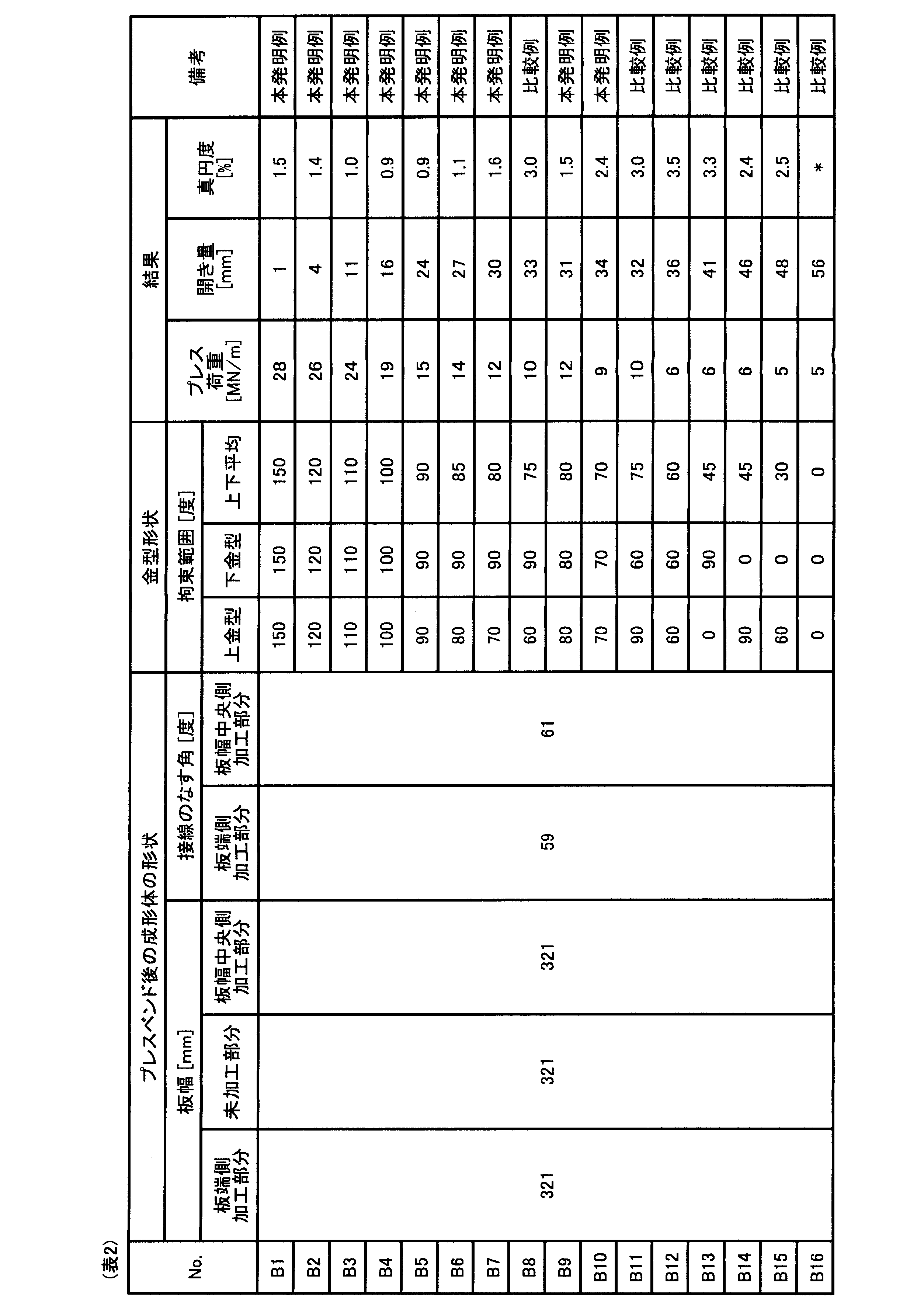
- Example 1 A bevel was provided using an edge mirror, and a plate width W was processed to 1928 [mm].
- Tables 1 and 2 show the shapes of the compacts A and B.
- the first alphabets A and B in “No.” in Tables 1 and 2 indicate the shape of the molded body (molded bodies A and B). The combination of the constraint range of the mold 4 and the lower mold 5 is shown.
- an unprocessed portion was provided with a width of 160 [mm] (W / 12) centering on the W / 4 part from the end of the plate width, and a tangent line at the end of the plate width and a W / 4 part.
- the molded body A is shown in which the angles ⁇ 21 and ⁇ 22 formed by the tangents are 65 degrees, and the angles ⁇ 11 and ⁇ 12 formed by the tangents at the center of the plate width and the tangents at the W / 4 part are 73 degrees.
- the molded body A After measuring, after forming a steel pipe having an outer diameter of 654 [mm] by welding seam gap portion G of the open pipe S 2, The diameter was measured at eight locations at a pitch of 22.5 degrees in the circumferential direction, and the difference between the maximum and the minimum of the diameter was determined. Tables 1 and 2 also show the mold shape (restriction range), press load, opening amount, and roundness. The roundness at this time is a number obtained by dividing the difference between the maximum and the minimum by the outer diameter of the steel pipe (the average value of all the measured values of the diameter).
- the opening amount after the O-press exceeds 40 [mm]
- the opening cannot be closed, and the opening is closed by another press machine.
- full welding of the entire length of the seam gap portion G was performed.
- 2.5 [%] was used as a guideline for acceptance before pipe expansion. This is because if the roundness before expansion is 2.5 [%] or less, the roundness after expansion can be a favorable value of 1.0 [%] or less.
- the constraint range of the upper mold 4 and the lower mold 5 is a combination of 60 degrees and 90 degrees.
- the opening amount is small, but the roundness is poor.
- No. 1 in Table 1 where the average value of the constraint range is 60 degrees or less.
- the opening amount is large.
- the roundness could not be measured because the welded portion after welding the seam gap G was broken.
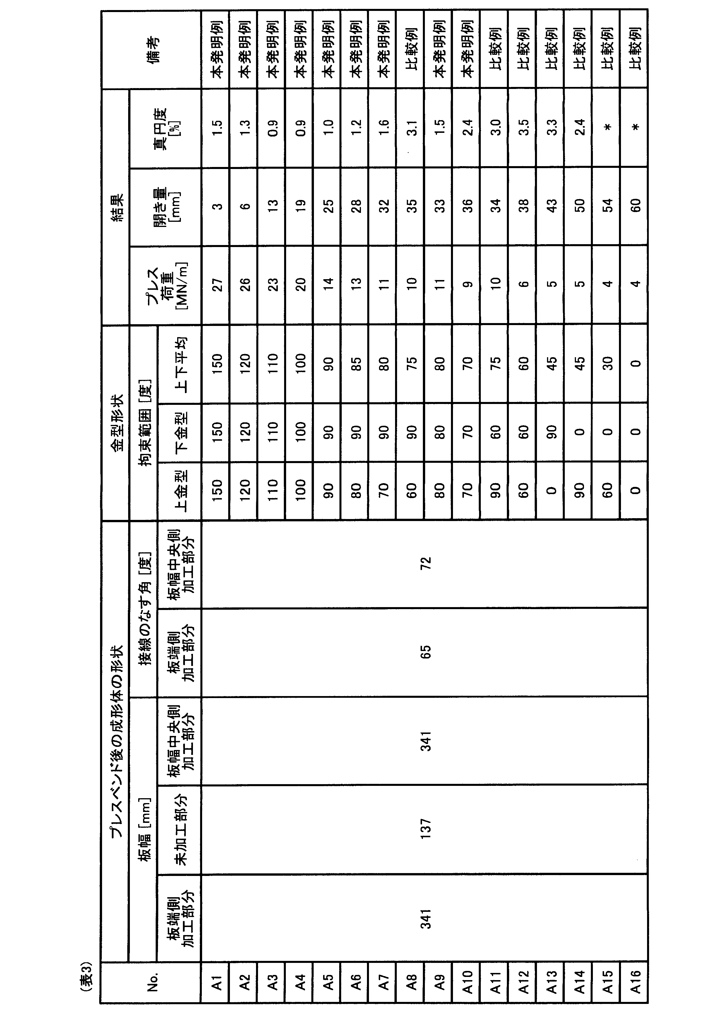
- an unprocessed portion was provided with a width of 137 [mm] (W / 12) centered on the W / 4 part from the plate width end, and a tangent line at the plate width end and a W / 4 part in the W / 4 part.
- the molded body A is shown in which the angles ⁇ 21 and ⁇ 22 formed by the tangents are 65 degrees, and the angles ⁇ 11 and ⁇ 12 formed by the tangents at the center of the plate width and the tangents at the W / 4 part are 72 degrees.
- an unprocessed portion is provided with a width of 273 [mm] (W / 6) (twice the width of the condition A) centering on W / 4 from the edge of the sheet width,
- the angles ⁇ 21 and ⁇ 22 formed by the tangent and the tangent at the W / 4 part are 59 degrees, and the angles ⁇ 11 and ⁇ 12 formed by the tangent at the center of the plate width and the tangent at the W / 4 part are 61 degrees.
- Body B is shown.
- the compacts A and B are symmetrical with respect to a straight line connecting the center of the plate width end and the plate width 1/2, and Tables 3 and 4 show the values of the plate width 1/2. Is shown.
- the amount of reduction during the O-press was set such that the distance between the outer surface side of the W / 2 part and the outer surface side of the plate width end was 553 [mm].
- the opening amount after the O-press exceeds 40 [mm]
- the opening cannot be closed, and the opening is closed by another press machine.
- full welding of the entire length of the seam gap portion G was performed.
- 2.5 [%] was used as a guideline for acceptance before the pipe expansion was reduced to 1.0 [%] or less by pipe expansion.
- No. 3 in Table 3 which is the range of the present invention example.
- Nos. A1 to A7, A9, and A10 in Table 4 In B1 to B7, B9, and B10, the opening amount is small and the roundness is good. In particular, in the case where the constrained range is 90 degrees to 110 degrees, the roundness is 1.0% or less without performing tube expansion. Also, the smaller the average value of the constraint range, the smaller the press load.
- condition A an unprocessed portion was provided with a width of 224 [mm] (W / 12) centered on the W / 4 part from the plate width end, and a tangent line at the plate width end and a W / 4 part
- the molded body A is shown in which the angles ⁇ 21 and ⁇ 22 formed by the tangents are 73 degrees, and the angles ⁇ 11 and ⁇ 12 formed by the tangents at the center of the plate width and the tangents at the W / 4 part are 72 degrees.
- condition B an unprocessed portion is provided with a width of 448 [mm] (W / 6) centered on W / 4 from the plate width end (twice the width of the condition A).
- the molded body A After measuring, after forming a steel pipe having an outer diameter of 905 [mm] by welding seam gap portion G of the open pipe S 2, The diameter was measured at eight locations at a pitch of 22.5 degrees in the circumferential direction, and the difference between the maximum and the minimum of the diameter was determined.
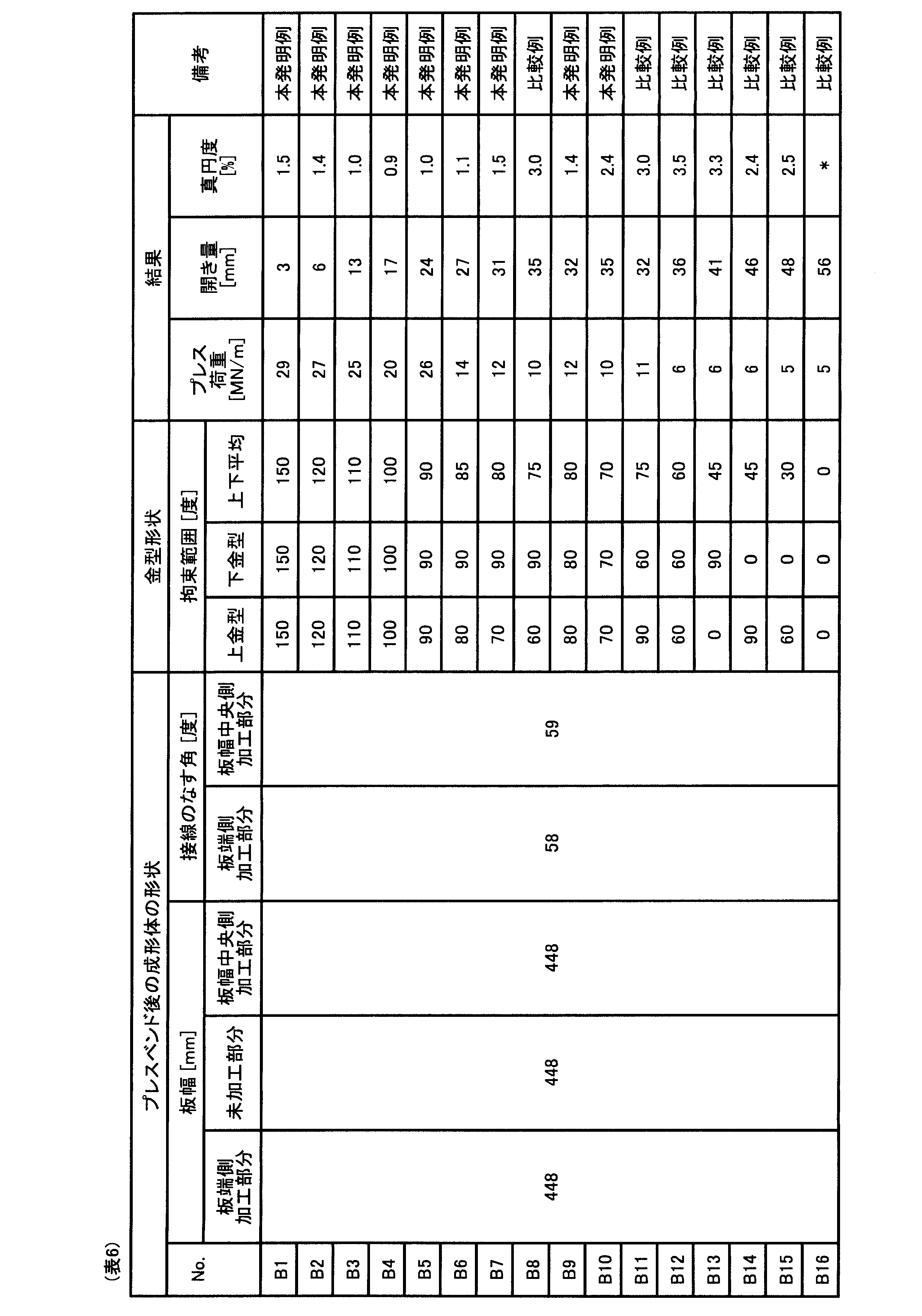
- Tables 5 and 6 also show the mold shape (restriction range), press load, opening amount, and roundness. The roundness at this time is a number obtained by dividing the difference between the maximum and the minimum by the outer diameter of the steel pipe.
- the opening amount after the O-press exceeds 40 [mm]
- the opening cannot be closed, and the opening is closed by another press machine.
- full welding of the entire length of the seam gap portion G was performed.
- 2.5 [%] was used as a guideline for acceptance before the pipe expansion was reduced to 1.0 [%] or less by pipe expansion.
- No. 5 of Table 5 which is the range of the present invention example. Nos. A1 to A7, A9, and A10; In B1 to B7, B9, and B10, the opening amount is small and the roundness is good. In particular, in the case where the constrained range is 90 degrees to 110 degrees, the roundness is 1.0% or less without performing tube expansion. Also, the smaller the average value of the constraint range, the smaller the press load.
- the constraint range of the upper mold 4 and the lower mold 5 is a combination of 60 degrees and 90 degrees.
- the opening amount is small, but the roundness is poor.
- the average value of the restraint range is 60 degrees or less.
- the roundness could not be measured because the welded portion after welding the seam gap G was broken.
- the press load and the roundness were substantially the same as those using the molded body A, but the opening amount was larger. Is getting smaller.
- an unprocessed portion is provided with a width of W / 12 centered on the W / 4 part from the end of the plate width in accordance with the initial width W of the plate, and a tangent at the end of the plate width and W /
- the angles ⁇ 21 and ⁇ 22 formed by the tangents in the four parts were set to 75 degrees
- the angles ⁇ 11 and ⁇ 12 formed by the tangents in the center part of the plate width and the tangents in the W / 4 part were set to 75 degrees.
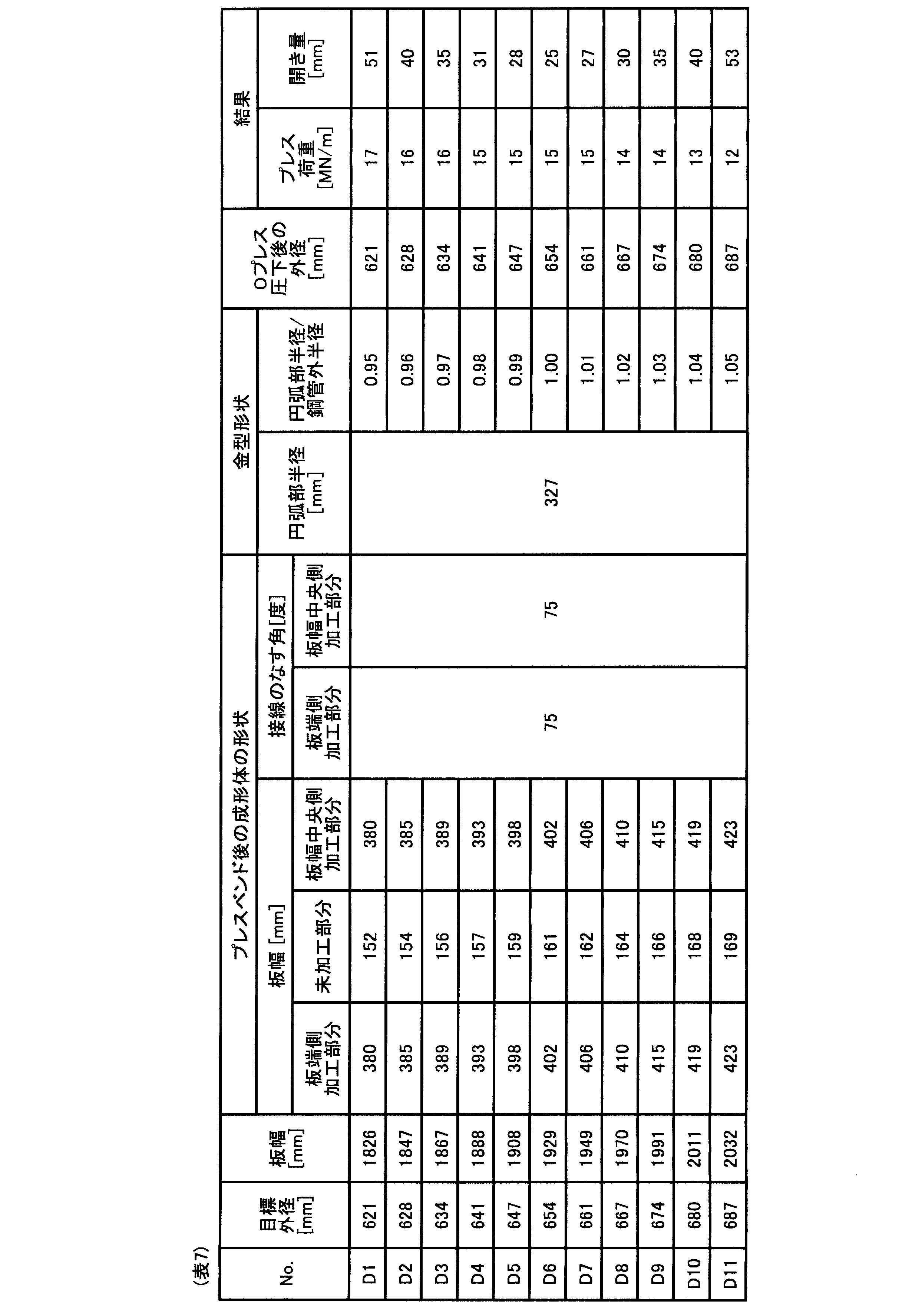
- the distance between the outer surface side of the W / 2 part and the outer surface side of the plate width end was reduced so as to be a value corresponding to the initial plate width W as shown in Table 7.
- Table 7 shows the outer diameter of the steel pipe after O-press reduction.
- the ratio of the circular arc radius to the outer radius of the steel pipe is 1.00.
- the opening amount that can be closed by the welding machine used in Example 1 is 40 [mm] or less.
- D2 to D10, and the ratio of the radius of the arc to the outer radius of the steel pipe is 0.96 to 1.04.
- the opening amount of 50 [mm] at which the welded portion did not break was the same as in No. 7 of Table 7.
- D2 to D10, and the ratio of the radius of the arc to the outer radius of the steel pipe is 0.96 to 1.04.
- the opening amount at which the seam gap G can be closed by welding and the opening amount at which the welded portion does not break vary depending on the welding equipment and the welding method, but the radius of the arc portion of the upper mold 4 and the lower mold 5 is different. Is 0.96 to 1.04 of the outer radius of the steel pipe.
Landscapes
- Engineering & Computer Science (AREA)
- Mechanical Engineering (AREA)
- Bending Of Plates, Rods, And Pipes (AREA)
- Metal Extraction Processes (AREA)
Abstract
Description
2|A-B|/(A+B)<0.4 ・・・(1)
ここで、|A-B|は、A-Bの絶対値を示す。
2|A-B|/(A+B)<0.4 ・・・(1)
ここで、|A-B|は、A-Bの絶対値を示す。
また、式(1)の意味については、後で詳述する。
2|A-B|/(A+B)<0.4 ・・・(1)
ここで、|A-B|は、A-Bの絶対値を示す。
エッジミラーを用いて開先を設けて、板幅Wを1928[mm]に加工した、長さ1000[mm]、板厚40[mm]、引張強度635[MPa]の鋼板に、端曲げを行った後、プレスベンド加工を行った成形体S1を準備した。次に、この成形体S1に対し、様々な拘束範囲の上金型4及び下金型5を用いて、30[MN]のプレス機によりOプレスを行うことで、成形体A,Bを成形した。表1及び表2に、成形体A,Bの形状を示す。なお、表1及び表2の「No.」における最初のアルファベットA,Bは、成形体の形状(成形体A,B)を示しており、そのアルファベットA,Bの後の数字は、上金型4及び下金型5の拘束範囲の組み合わせを示している。

エッジミラーを用いて開先を設けて板幅1639[mm]に加工した、長さ1000[mm]、板厚31.8[mm]、引張強度779[MPa]の鋼板に、端曲げを行った後、プレスベンド加工を行った成形体S1を準備した。次に、この成形体S1に対し、様々な拘束範囲の上金型4及び下金型5を用いて、30[MN]のプレス機によりOプレスを行うことで、成形体A,Bを成形した。表3及び表4に、成形体A,Bの形状を示す。なお、表3及び表4の「No.」における最初のアルファベットA,Bは、成形体の形状(成形体A,B)を示しており、そのアルファベットA,Bの後の数字は、上金型4及び下金型5の拘束範囲の組み合わせを示している。

エッジミラーを用いて開先を設けて板幅2687[mm]に加工した、長さ1000[mm]、板厚50.8[mm]、引張強度779[MPa]の鋼板に、端曲げを行った後、プレスベンド加工を行った成形体S1を準備した。次に、この成形体S1に対し、様々な拘束範囲の上金型4及び下金型5を用いて、30[MN]のプレス機によりOプレスを行うことで、成形体A,Bを成形した。表5及び表6に、成形体A,Bの形状を示す。なお、表5及び表6の「No.」における最初のアルファベットA,Bは、成形体の形状(成形体A,B)を示しており、そのアルファベットA,Bの後の数字は、上金型4及び下金型5の拘束範囲の組み合わせを示している。

目標外径621[mm]~687[mm]の鋼管を製造するために、エッジミラーを用いて開先を設けて板幅1826~2032[mm]に加工した、長さ1000[mm]、板厚40[mm]、引張強度635[MPa]の鋼板に、端曲げを行った後、プレスベンド加工を行った成形体S1を準備した。次に、この成形体S1に対し、円弧部半径327mm、拘束範囲45度の様々な上金型4及び下金型5を用いて、30[MN]のプレス機によりOプレスを行い、成形体D1~D11を成形した。表7に成形体D1~D11の成形条件を示す。成形体D1~D11には、初期の板幅Wに応じて、板幅端からW/4部を中心にW/12の幅で未加工部を設け、板幅端部における接線と、W/4部における接線とのなす角θ21,θ22を75度とし、板幅中央部における接線と、W/4部における接線とのなす角θ11,θ12を75度とした。また、OプレスではW/2部の外面側と板幅端部の外面側との距離が、表7に示すように初期の板幅Wに対応した値となるように圧下した。また、表7に、Oプレス圧下後の鋼管の外径を示す。
1a 棒状部材
1b 棒状部材
2 パンチ
2a パンチ先端部
2b パンチ支持体
3 搬送ローラ
4 上金型
4a 円弧部
4b1 直線部または小曲率円弧部
4b2 直線部または小曲率円弧部
5 下金型
5a 円弧部
5b1 直線部または小曲率円弧部
5b2 直線部または小曲率円弧部
Claims (10)
- 幅方向両端部に端曲げ加工が施された板材に、その幅方向に沿って3回以上の曲げ加工を施してU字状断面をなす成形体を成形し、次いで、該成形体にプレス加工を施すことにより、その長手方向にシームギャップ部を有する管体であるオープン管とした後、該シームギャップ部を接合して鋼管とする鋼管の製造方法であって、
前記端曲げ加工前の前記板材の幅を板幅Wとしたとき、
前記成形体は、板幅端部からW/4だけ離れた部位を中心に、他の領域に比較して小さな曲率を付与した軽加工部、または、曲げ加工を省略した未加工部を有し、
前記オープン管の形状が、前記U字状断面の最下部を中心に前記板幅Wの20[%]以上の範囲と、前記板幅端から前記板幅Wの10[%]以上の範囲とが、前記鋼管の外径と同径または略同径の円弧に内接する形状となるように、
プレス加工することを特徴とする鋼管の製造方法。 - 前記鋼管の外径と同径または略同径の円弧に内接する前記U字状断面の最下部を中心に前記板幅Wの20[%]以上の範囲をAとし、前記鋼管の外径と同径または略同径の円弧に内接する板幅両端から前記板幅Wの10[%]以上の範囲の合計をBとしたとき、式(1)を満たすことを特徴とする請求項1に記載の鋼管の製造方法。
2|A-B|/(A+B)<0.4 ・・・(1)
ここで、|A-B|は、A-Bの絶対値を示す。 - 一対の金型のうちの一方の金型と前記成形体のU字開放側とが対向するように他方の金型に該成形体を載置して、該一対の金型で該成形体を挟み込んで該成形体にプレス加工を施すにあたり、
前記他方の金型は、
前記他方の金型に前記成形体を載置した状態で、前記U字状断面の最下部を中心に、前記鋼管の外径と同径または略同径の円弧に内接する形状となる範囲を除いて前記成形体が接触せず、
プレス加工が完了した状態で、前記他方の金型の一部に前記オープン管に接触しない加工面を備えており、
前記一方の金型は、
前記他方の金型に前記成形体を載置した状態で、前記成形体が接触せず、
プレス加工が完了した状態で、前記一方の金型の一部に前記オープン管に接触しない加工面を備えたことを特徴とする請求項1または2に記載の鋼管の製造方法。 - 前記鋼管の外半径に相当する半径に対して±3.5[%]の範囲にある円弧部の半径を有する金型を用いてプレス加工を実施することを特徴とする請求項1乃至3のいずれか1項に記載の鋼管の製造方法。
- 前記成形体のプレス加工に際して、前記成形体のプレス加工に用いるプレス金型の中心と、前記成形体の幅方向の中心とが一致していることを特徴とする請求項1乃至4のいずれか1項に記載の鋼管の製造方法。
- 前記成形体は、U字開放側を上方に向けたU字姿勢に保持されることを特徴とする請求項1乃至5のいずれか1項に記載の鋼管の製造方法。
- 請求項1乃至6のいずれか1項に記載の鋼管の製造方法において使用するプレス金型であって、
前記プレス金型は、前記成形体を挟持する一対の押圧体からなり、各金型の前記成形体と接触し得る面には、各金型の加工中心と一致する位置に円弧中心が位置するように、前記鋼管の外半径に相当する半径に対して±3.5[%]の範囲にある半径の円弧部が形成されており、
各金型における前記円弧部の中心角が70度以上であり、両金型の前記中心角の角度の合計が360度未満であることを特徴とするプレス金型。 - 両金型の前記中心角の角度が同じであることを特徴とする請求項7に記載のプレス金型。
- 各金型は、前記円弧部の円弧方向両端にそれぞれつながった、直線部、または、該円弧部よりも曲率が小さい小曲率円弧部を有することを特徴とする請求項7または8に記載のプレス金型。
- 請求項7乃至9のいずれか1項に記載のプレス金型を用いることを特徴とする、請求項1乃至6のいずれか1項に記載の鋼管の製造方法。
Priority Applications (7)
| Application Number | Priority Date | Filing Date | Title |
|---|---|---|---|
| JP2019547161A JP6791397B2 (ja) | 2018-09-14 | 2018-09-14 | 鋼管の製造方法及びプレス金型 |
| PCT/JP2018/034145 WO2020054051A1 (ja) | 2018-09-14 | 2018-09-14 | 鋼管の製造方法及びプレス金型 |
| CN201880097036.2A CN112638558B (zh) | 2018-09-14 | 2018-09-14 | 钢管的制造方法及冲压模具 |
| KR1020217006550A KR102425607B1 (ko) | 2018-09-14 | 2018-09-14 | 강관의 제조 방법 및 프레스 금형 |
| RU2021110038A RU2769596C1 (ru) | 2018-09-14 | 2018-09-14 | Способ изготовления стальной трубы и матрица |
| BR112021004322-5A BR112021004322B1 (pt) | 2018-09-14 | Método de produção de tubo de aço | |
| EP18933413.9A EP3851220B1 (en) | 2018-09-14 | 2018-09-14 | Steel pipe manufacturing method and press die |
Applications Claiming Priority (1)
| Application Number | Priority Date | Filing Date | Title |
|---|---|---|---|
| PCT/JP2018/034145 WO2020054051A1 (ja) | 2018-09-14 | 2018-09-14 | 鋼管の製造方法及びプレス金型 |
Publications (1)
| Publication Number | Publication Date |
|---|---|
| WO2020054051A1 true WO2020054051A1 (ja) | 2020-03-19 |
Family
ID=69777023
Family Applications (1)
| Application Number | Title | Priority Date | Filing Date |
|---|---|---|---|
| PCT/JP2018/034145 Ceased WO2020054051A1 (ja) | 2018-09-14 | 2018-09-14 | 鋼管の製造方法及びプレス金型 |
Country Status (6)
| Country | Link |
|---|---|
| EP (1) | EP3851220B1 (ja) |
| JP (1) | JP6791397B2 (ja) |
| KR (1) | KR102425607B1 (ja) |
| CN (1) | CN112638558B (ja) |
| RU (1) | RU2769596C1 (ja) |
| WO (1) | WO2020054051A1 (ja) |
Families Citing this family (1)
| Publication number | Priority date | Publication date | Assignee | Title |
|---|---|---|---|---|
| CN117299853B (zh) * | 2023-11-22 | 2026-02-03 | 中国二十二冶集团有限公司 | 提高厚钢板压制圆管圆度的方法 |
Citations (13)
| Publication number | Priority date | Publication date | Assignee | Title |
|---|---|---|---|---|
| US4149399A (en) | 1977-01-11 | 1979-04-17 | Ab Carbox | Method of forming tubes or pipes |
| JPH11285729A (ja) * | 1998-04-01 | 1999-10-19 | Sumitomo Metal Ind Ltd | Uoe鋼管の製造方法 |
| JP2002178026A (ja) | 2000-12-15 | 2002-06-25 | Kawasaki Steel Corp | Uoeパイプの製造方法 |
| JP2003039115A (ja) | 2001-07-30 | 2003-02-12 | Kawasaki Steel Corp | Uoe管のoプレス用金型およびuoe管の製造方法 |
| JP2004082219A (ja) | 2002-07-15 | 2004-03-18 | Sms Meer Gmbh | 金属板から管を製造するための装置 |
| JP2005021907A (ja) | 2003-06-30 | 2005-01-27 | Kawasaki Hydromechanics Corp | パイププレス成形方法 |
| JP2005324255A (ja) | 2005-06-17 | 2005-11-24 | Nakajima Steel Pipe Co Ltd | 丸鋼管の製造方法 |
| JP2011056524A (ja) | 2009-09-08 | 2011-03-24 | Sumitomo Heavy Industries Techno-Fort Co Ltd | 板曲げプレス |
| JP2012250285A (ja) | 2011-05-31 | 2012-12-20 | Sms Meer Gmbh | 板材からスリット管を製造する方法及び装置 |
| WO2014188468A1 (ja) | 2013-05-20 | 2014-11-27 | Jfeスチール株式会社 | ベンディングプレス装置およびベンディングプレス方法ならびに鋼管の製造装置および鋼管の製造方法 |
| WO2014192043A1 (ja) | 2013-05-30 | 2014-12-04 | Jfeスチール株式会社 | 鋼管のプレス成形方法および鋼管の製造方法 |
| WO2016084607A1 (ja) | 2014-11-25 | 2016-06-02 | Jfeスチール株式会社 | 鋼管の製造方法及びその方法に使用するプレス金型 |
| WO2018168563A1 (ja) * | 2017-03-15 | 2018-09-20 | Jfeスチール株式会社 | プレス金型及び鋼管の製造方法 |
Family Cites Families (10)
| Publication number | Priority date | Publication date | Assignee | Title |
|---|---|---|---|---|
| DE3632952A1 (de) * | 1986-09-27 | 1988-04-07 | Hoesch Ag | Verfahren und vorrichtung zur kontinuierlichen herstellung rohrfoermiger koerper mittels laser-laengsnahtschweissung |
| JP2001009524A (ja) * | 1999-06-30 | 2001-01-16 | Toyota Motor Corp | 筒状体の製造方法 |
| KR100530325B1 (ko) * | 2001-04-30 | 2005-11-22 | 주식회사 포스코 | 가변식 스트립 선단부 절곡장치 |
| JP5135540B2 (ja) * | 2007-06-28 | 2013-02-06 | 新日鐵住金株式会社 | 鋼管製造設備及び鋼管製造方法 |
| KR20100106700A (ko) * | 2009-03-24 | 2010-10-04 | 진영희 | 자동차의 고무부싱용 관체 및 그 제조방법 |
| JP5696357B2 (ja) * | 2009-11-27 | 2015-04-08 | セイコーエプソン株式会社 | 搬送ローラーの製造方法、搬送ローラー、印刷装置 |
| CA2868973C (en) * | 2012-04-02 | 2016-11-01 | Jfe Steel Corporation | Uoe steel pipe and structure |
| CN105246613B (zh) * | 2013-05-24 | 2017-03-08 | 杰富意钢铁株式会社 | 钢管的制造方法 |
| JP6070967B2 (ja) * | 2013-05-29 | 2017-02-01 | Jfeスチール株式会社 | 溶接鋼管の製造方法 |
| JP6262166B2 (ja) * | 2014-03-31 | 2018-01-17 | Jfeスチール株式会社 | ベンディングプレス成形用金型 |
-
2018
- 2018-09-14 JP JP2019547161A patent/JP6791397B2/ja active Active
- 2018-09-14 WO PCT/JP2018/034145 patent/WO2020054051A1/ja not_active Ceased
- 2018-09-14 EP EP18933413.9A patent/EP3851220B1/en active Active
- 2018-09-14 CN CN201880097036.2A patent/CN112638558B/zh active Active
- 2018-09-14 KR KR1020217006550A patent/KR102425607B1/ko active Active
- 2018-09-14 RU RU2021110038A patent/RU2769596C1/ru active
Patent Citations (13)
| Publication number | Priority date | Publication date | Assignee | Title |
|---|---|---|---|---|
| US4149399A (en) | 1977-01-11 | 1979-04-17 | Ab Carbox | Method of forming tubes or pipes |
| JPH11285729A (ja) * | 1998-04-01 | 1999-10-19 | Sumitomo Metal Ind Ltd | Uoe鋼管の製造方法 |
| JP2002178026A (ja) | 2000-12-15 | 2002-06-25 | Kawasaki Steel Corp | Uoeパイプの製造方法 |
| JP2003039115A (ja) | 2001-07-30 | 2003-02-12 | Kawasaki Steel Corp | Uoe管のoプレス用金型およびuoe管の製造方法 |
| JP2004082219A (ja) | 2002-07-15 | 2004-03-18 | Sms Meer Gmbh | 金属板から管を製造するための装置 |
| JP2005021907A (ja) | 2003-06-30 | 2005-01-27 | Kawasaki Hydromechanics Corp | パイププレス成形方法 |
| JP2005324255A (ja) | 2005-06-17 | 2005-11-24 | Nakajima Steel Pipe Co Ltd | 丸鋼管の製造方法 |
| JP2011056524A (ja) | 2009-09-08 | 2011-03-24 | Sumitomo Heavy Industries Techno-Fort Co Ltd | 板曲げプレス |
| JP2012250285A (ja) | 2011-05-31 | 2012-12-20 | Sms Meer Gmbh | 板材からスリット管を製造する方法及び装置 |
| WO2014188468A1 (ja) | 2013-05-20 | 2014-11-27 | Jfeスチール株式会社 | ベンディングプレス装置およびベンディングプレス方法ならびに鋼管の製造装置および鋼管の製造方法 |
| WO2014192043A1 (ja) | 2013-05-30 | 2014-12-04 | Jfeスチール株式会社 | 鋼管のプレス成形方法および鋼管の製造方法 |
| WO2016084607A1 (ja) | 2014-11-25 | 2016-06-02 | Jfeスチール株式会社 | 鋼管の製造方法及びその方法に使用するプレス金型 |
| WO2018168563A1 (ja) * | 2017-03-15 | 2018-09-20 | Jfeスチール株式会社 | プレス金型及び鋼管の製造方法 |
Non-Patent Citations (1)
| Title |
|---|
| See also references of EP3851220A4 |
Also Published As
| Publication number | Publication date |
|---|---|
| EP3851220B1 (en) | 2025-01-29 |
| JPWO2020054051A1 (ja) | 2020-12-17 |
| EP3851220A1 (en) | 2021-07-21 |
| EP3851220A4 (en) | 2021-09-22 |
| KR102425607B1 (ko) | 2022-07-27 |
| KR20210041032A (ko) | 2021-04-14 |
| BR112021004322A2 (pt) | 2021-07-20 |
| CN112638558B (zh) | 2022-12-16 |
| CN112638558A (zh) | 2021-04-09 |
| JP6791397B2 (ja) | 2020-11-25 |
| RU2769596C1 (ru) | 2022-04-04 |
Similar Documents
| Publication | Publication Date | Title |
|---|---|---|
| JP6721108B2 (ja) | プレス金型及び鋼管の製造方法 | |
| KR101945091B1 (ko) | 벤딩 프레스 성형용 금형 | |
| EP3225321A1 (en) | Method for manufacturing steel pipe and press mold used in said method | |
| JP6070967B2 (ja) | 溶接鋼管の製造方法 | |
| JP2012170977A (ja) | 鋼管の製造方法 | |
| KR101712885B1 (ko) | 강관의 제조 방법 | |
| JP6566231B1 (ja) | 鋼板の端曲げ方法および装置並びに鋼管の製造方法および設備 | |
| JP6791397B2 (ja) | 鋼管の製造方法及びプレス金型 | |
| CN111954579A (zh) | 成型品的制造方法 | |
| KR101382788B1 (ko) | 조관 방법 및 c 성형기 | |
| EP3778051A1 (en) | Method and device for bending edge of steel plate, and steel pipe manufacturing method and equipment | |
| JPH07275954A (ja) | 電縫鋼管の製造方法 | |
| CN114570808B (zh) | 一种新型热推弯头用牛角芯棒 | |
| JP2019177398A (ja) | 鋼板の端曲げ方法および装置並びに鋼管の製造方法および設備 | |
| JPS60238040A (ja) | 直管部付エルボの製造方法 |
Legal Events
| Date | Code | Title | Description |
|---|---|---|---|
| ENP | Entry into the national phase |
Ref document number: 2019547161 Country of ref document: JP Kind code of ref document: A |
|
| 121 | Ep: the epo has been informed by wipo that ep was designated in this application |
Ref document number: 18933413 Country of ref document: EP Kind code of ref document: A1 |
|
| NENP | Non-entry into the national phase |
Ref country code: DE |
|
| REG | Reference to national code |
Ref country code: BR Ref legal event code: B01A Ref document number: 112021004322 Country of ref document: BR |
|
| ENP | Entry into the national phase |
Ref document number: 2018933413 Country of ref document: EP Effective date: 20210414 |
|
| ENP | Entry into the national phase |
Ref document number: 112021004322 Country of ref document: BR Kind code of ref document: A2 Effective date: 20210308 |