WO2020054094A1 - Procédé de correction de données de mesure pour dispositif de balayage à lumière laser tridimensionnel - Google Patents
Procédé de correction de données de mesure pour dispositif de balayage à lumière laser tridimensionnel Download PDFInfo
- Publication number
- WO2020054094A1 WO2020054094A1 PCT/JP2019/005776 JP2019005776W WO2020054094A1 WO 2020054094 A1 WO2020054094 A1 WO 2020054094A1 JP 2019005776 W JP2019005776 W JP 2019005776W WO 2020054094 A1 WO2020054094 A1 WO 2020054094A1
- Authority
- WO
- WIPO (PCT)
- Prior art keywords
- point cloud
- cloud data
- laser light
- error parameter
- mechanical error
- Prior art date
- Legal status (The legal status is an assumption and is not a legal conclusion. Google has not performed a legal analysis and makes no representation as to the accuracy of the status listed.)
- Ceased
Links
Images



Classifications
-
- G—PHYSICS
- G01—MEASURING; TESTING
- G01C—MEASURING DISTANCES, LEVELS OR BEARINGS; SURVEYING; NAVIGATION; GYROSCOPIC INSTRUMENTS; PHOTOGRAMMETRY OR VIDEOGRAMMETRY
- G01C15/00—Surveying instruments or accessories not provided for in groups G01C1/00 - G01C13/00
-
- G—PHYSICS
- G01—MEASURING; TESTING
- G01C—MEASURING DISTANCES, LEVELS OR BEARINGS; SURVEYING; NAVIGATION; GYROSCOPIC INSTRUMENTS; PHOTOGRAMMETRY OR VIDEOGRAMMETRY
- G01C3/00—Measuring distances in line of sight; Optical rangefinders
-
- G—PHYSICS
- G01—MEASURING; TESTING
- G01C—MEASURING DISTANCES, LEVELS OR BEARINGS; SURVEYING; NAVIGATION; GYROSCOPIC INSTRUMENTS; PHOTOGRAMMETRY OR VIDEOGRAMMETRY
- G01C3/00—Measuring distances in line of sight; Optical rangefinders
- G01C3/02—Details
- G01C3/06—Use of electric means to obtain final indication
-
- G—PHYSICS
- G02—OPTICS
- G02B—OPTICAL ELEMENTS, SYSTEMS OR APPARATUS
- G02B26/00—Optical devices or arrangements for the control of light using movable or deformable optical elements
- G02B26/08—Optical devices or arrangements for the control of light using movable or deformable optical elements for controlling the direction of light
- G02B26/10—Scanning systems
Definitions
- the present disclosure relates to a measurement data calibration method for a three-dimensional laser light scanning device.
- the point cloud data is a group of three-dimensional coordinate value data, such as data representing the shape of an object existing in the surrounding environment.
- a method such as a technique disclosed in Japanese Patent Application Laid-Open No. 2017-134293 (see Patent Document 1) is known.
- the emission direction of the laser light actually differs from the design due to variations in the dimensions of components and errors in the adjustment of the optical axis, and does not exactly match. Therefore, it is necessary to mechanically adjust the components of the three-dimensional laser light scanning device so that the difference falls within a certain range. However, it is very difficult to obtain the required accuracy of the point cloud data only by mechanical adjustment, which causes a cost increase. Therefore, an operation of improving the accuracy of the point cloud by measuring the mechanical deviation of the components of the three-dimensional laser light scanning device and calculating the actual measurement direction has been performed. These operations are called calibration, and are usually performed in the manufacturing process of the three-dimensional laser light scanning device.
- the present disclosure has been made in order to solve these problems, the mechanical deviation of the components that affect the measurement accuracy of the three-dimensional laser light scanning device is selected as a mechanical error parameter, the measured point cloud data.
- the present invention proposes a method for performing calibration for correction. It is an object of the present invention to provide a method for calibrating measurement data of a three-dimensional laser light scanning device, in which a user himself can easily calibrate the three-dimensional laser light scanning device and improve measurement accuracy.
- a laser light measuring device that measures the distance by projecting laser light and receiving reflected light from an object to be illuminated, and irradiating by reflecting laser light emitted from the laser light measuring device on a reflecting surface.
- a reflecting mirror that irradiates the body with light, reflects reflected light from the irradiated body on the reflecting surface and receives the reflected light, a first driving unit that drives the reflecting mirror to rotate about a horizontal rotation axis, and the laser light.
- a rotation support unit that supports and fixes the distance measurement device and the first drive unit, a second drive unit that rotationally drives the rotation support unit about a vertical axis, the laser light distance measurement device, the first drive unit, A control unit that controls the operation of a second drive unit, wherein the control unit controls the first drive unit and the second drive unit to reflect the laser light of the rotationally driven reflecting mirror.
- the horizontal and vertical directions respectively By controlling the laser beam distance measuring device while maintaining a constant rotation speed, the laser beam distance measuring device performs laser beam ranging, so that a virtual spherical surface of an arbitrary radius centered on the reflecting mirror is formed.
- the data is stratified into two sets of point cloud data A and point cloud data B, a predetermined mechanical error parameter is selected, and the selected machine error parameter is determined for the point cloud data A and the point cloud data B.
- the method is characterized in that the coordinate values of the markers are obtained from the respective point cloud data by applying and compared, and a correction value of the mechanical error parameter is obtained so that the difference between the coordinate values is equal to or less than a predetermined threshold.
- the point cloud data obtained during one rotation of the slower one of the horizontal rotation speed and the vertical rotation speed in the direction of reflecting the laser light of the reflector of the laser light distance measuring device is referred to as point cloud data.
- a and a group of point cloud data B are stratified, a predetermined mechanical error parameter is selected, and the selected machine error parameter is applied to the point cloud data A and the point cloud data B to obtain each point cloud data.
- the coordinate values of the markers are obtained and compared, and a correction value of the mechanical error parameter is calculated so that the difference between the coordinate values is equal to or less than a predetermined threshold.
- the calibration ends when the sum of the squares of the difference between the coordinate values of the markers obtained in the point cloud data A and the point cloud data B falls below the target value. Thereby, calibration can be performed by using the point cloud data easily measured by the user himself using the three-dimensional laser light scanning device, and the measurement accuracy can be improved.
- En and Fn when the difference between the coordinate values of the markers converges to be the smallest below a predetermined threshold value as the correction value.
- the mechanical error parameter is at least any one of a Z-phase shift of the reflecting mirror, an angular error, a tilt angle or a tilt direction, a tilt angle or a tilt direction of the laser beam distance measuring device, and a tilt angle or a tilt direction of the laser optical axis. It is desirable to include a plurality. Thereby, when the dimensional accuracy of the three-dimensional laser light scanning device is sufficiently high, the coordinate values of the markers obtained by each of the point cloud data A and the point cloud data B are very close values, Improve the coordinate accuracy of point clouds by reflecting the measurement accuracy caused by mechanical factors such as dimensional variations of components constituting the original laser beam scanning device, errors in optical axis adjustment, and measurement direction errors as well as mechanical error parameters. be able to.
- FIG. 5 is a table showing a correction table of a mechanical error parameter of FIG. 4.
- FIG. 1 is a front view of a three-dimensional laser light scanning device
- FIG. 2 is a perspective view thereof.
- a laser measuring unit 1 laser light measuring device
- emits a laser beam irradiates the object to be measured, receives laser light reflected from the object to be measured, and receives the laser beam. The linear distance between the object and the distance measurement object is measured.
- the laser beam emitted by the laser measurement unit 1 is once applied to the reflection mirror 2 (reflection mirror), and is irradiated toward the distance measurement object by utilizing the reflection on the mirror surface.
- the reflection mirror 2 a rod mirror is preferably used, which is obtained by diagonally cutting a columnar material (such as glass) and depositing silver or the like on the cut plane. Instead of vapor deposition, the mirror itself may be attached to the cutting plane.
- the central axis of the cylinder and the cutting plane have a 45-degree inclination angle.
- the reflecting mirror 2 is rotatably supported by a mirror driving motor 3 (first driving unit) so as to be rotatable around a central axis (horizontal rotation axis) of a cylinder.
- a mirror driving motor 3 first driving unit
- the laser beam from the laser measurement unit 1 is deflected in a direction of 90 degrees from the central axis (horizontal rotation axis) of the cylinder. Due to the rotation of the mirror 2, the laser beam for distance measurement is emitted toward all angles in the vertical direction.
- the mirror encoder 4 is for detecting an angle of rotation of the mirror 2 by the mirror drive motor 3.
- the laser measurement unit 1 and the mirror drive motor 3 are supported and fixed on a rotation support 5 (rotation support).
- the rotary support 5 has a support leg 5a mounted and fixed on the installation surface, and a fixed shaft 5b formed upright on the support leg 5a.
- the support base body 5c is rotatably supported on the fixed shaft 5b via a bearing 5c1.
- an upper support plate 5d is provided so as to protrude outward from the support base 5c in a direction orthogonal to the fixed shaft 5b.
- the laser measurement unit 1 and the control unit 6 are supported on the upper support plate 5d.
- An upright plate 5e is formed upright on the upper support plate 5d, and the mirror drive motor 3 is supported and fixed to the upright plate 5e.
- a lower support plate 5f is provided so as to protrude outward from the support base 5c in a direction orthogonal to the fixed shaft 5b.
- a spindle drive motor 7 (second drive unit) is supported and fixed with the motor shaft 7a facing downward.
- a motor gear 8a is provided integrally with the motor shaft 7a.
- the motor gear 8a meshes with a fixed gear 8b integrated with the fixed shaft 5b.
- a spindle encoder 9 is provided on the fixed shaft 5b. The spindle encoder 9 is for detecting an angle of rotation of the support base body 5c by the spindle drive motor 7.
- the control unit 6 controls the operations of the laser measurement unit 1, the mirror drive motor 3 and the spindle drive motor 7 as a whole.
- the control unit 6 obtains rotation information of the mirror drive motor 3 from the mirror encoder 4 and rotation information of the spindle drive motor 7 from the spindle encoder 9 and controls these rotation drives.
- the control unit 6 controls the laser drive unit 3 while controlling the mirror drive motor 3 and the spindle drive motor 7 to change the direction in which the reflection mirror 2 reflects the laser light, thereby performing laser light ranging. Do.
- the laser beam emitted by the laser measuring unit 1 is irradiated on the entire circumference in the vertical direction by rotating the laser beam irradiation direction by 90 ° by the reflection mirror 2 and rotating about the horizontal rotation axis, and
- the measurement unit 1 and the reflection mirror 2 rotate around the fixed shaft 5b together with the rotation support 5 to realize a global three-dimensional laser beam scanning with respect to the surroundings.
- laser light ranging is performed in a fixed pattern on the virtual spherical surface 10 which is the surface of a virtual sphere having an arbitrary radius centered on the reflection mirror 2.
- the assembly of the laser measuring unit 1, the mirror drive motor 3, the control unit 6, and the spindle drive motor 7 to the rotary support 5 is performed in consideration of the rotational balance of the rotary support 5 about the fixed shaft 5b. Is preferred.
- the weight balance is adjusted by the laser measurement unit 1 and the control unit 6, the mirror drive motor 3 and the spindle drive motor 7.
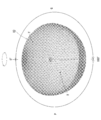
- FIG. 3 shows a case where a transparent sphere having an arbitrary radius virtually exists around the three-dimensional laser light scanning device, and a laser beam for distance measurement is placed on the surface of the sphere (hereinafter referred to as “virtual spherical surface 10”).
- virtual spherical surface 10 a laser beam for distance measurement is placed on the surface of the sphere.
- FIG. 4 is an image diagram showing what pattern (scanning pattern) a locus (scanning line) of the laser beam for distance measurement draws on a virtual spherical surface 10 as a result of the laser light being reflected by a reflection mirror 2.
- the rotation speed of the mirror drive motor 3 is set to be much higher than the rotation speed of the spindle drive motor 7. You have set.
- the laser light irradiated onto the virtual spherical surface 10 is dense in the latitude (vertical) direction and coarse in the longitude (horizontal) direction.
- the density at which the measurement is performed in the latitude and longitude directions can be adjusted by the rotational speed of each spindle and the measurement rate.
- the density of points irradiated with laser light near the north pole of the virtual spherical surface 10 increases.
- the rotation speed of the mirror drive motor 3 is significantly higher than the rotation speed of the spindle drive motor 7.
- the reflecting mirror 2 converts the laser light emitted by the laser measurement unit 1 into a virtual spherical surface 10 as illustrated in FIG.
- irradiation is performed so as to draw a fixed scanning pattern that is dense in the north-south direction and sparse in the east-west direction. This is an entire pattern drawn to explain the scanning pattern.
- the scanning line drawn by the laser beam on the virtual spherical surface 10 is not strictly an arc, but has a shape close to an arc in which the meridian is slightly distorted spirally in the east-west direction on the virtual spherical surface 10.
- the scanning line makes one round on a meridian at a certain longitude on the virtual spherical surface 10 (the scanning line does not exactly match the meridian).
- point cloud data A and point cloud data B These two sets of point cloud data are referred to as point cloud data A and point cloud data B, respectively.
- the point cloud data obtained at the horizontal rotation angles of 0 to 180 degrees and 180 to 360 degrees are the point cloud data A and the point cloud data B, respectively.
- the group data may be point cloud data A and point cloud data B, respectively.
- the processing may be performed using a larger number of point group data by making multiple rounds.
- the point cloud data A and the point cloud data B are congruent as the surrounding shape data, Coordinate values of markers (characteristics such as a checkerboard-shaped plate or a sphere) placed around for the purpose of calibration should show the same value.
- markers characteristics such as a checkerboard-shaped plate or a sphere
- the marker coordinate values obtained from the point cloud data A and the marker coordinate values obtained from the point cloud data B Will show different values.
- such a mechanical displacement of a component that affects the point cloud data is defined as a mechanical error parameter.
- mechanical error parameters there are a plurality of mechanical error parameters, each of which is treated as a numerical value.
- the acquired point cloud data is highly accurate when corrected by applying an appropriate machine error parameter, and the "difference in marker coordinate values" is extremely small.
- the gist of the present invention is to perform correction by applying a predetermined mechanical error parameter to the point cloud data A and the point cloud data B, obtain marker coordinate values from each point cloud data, and calculate two coordinate values. Comparing for differences, checking how these differences change when the machine error parameters are varied, and using the machine error parameters when the differences are small as appropriate, It is what we are going to do. That is, using two sets of congruent point cloud data A and point cloud data B, based on the fact that the marker coordinate values obtained from the respective point cloud data are originally the same, a machine error parameter is obtained by calculation. That's what it means.
- the horizontal rotation which is the slower of the horizontal rotation speed and the vertical rotation speed in the direction in which the laser light is reflected by the reflection mirror 2, makes one revolution, and two sets of point group data measured during this period. Stratified into point cloud data.
- the point group data obtained on the P side (0 ⁇ 180 ° of the reflection mirror 2) in the vertical direction while the laser beam reflecting direction of the reflection mirror 2 makes one round in the horizontal direction is represented by a point.
- the point cloud data obtained when the spindle drive motor 7 rotates from X (on the equator on the near side of the virtual spherical surface 10) to Y (0 ⁇ 180 °) in the horizontal direction is referred to as the point cloud data A, and similarly the same rotation.
- one of a plurality of mechanical error parameters is selected, and the numerical value of the mechanical error parameter is changed within a certain range with a certain amount of change. It is changed a plurality of times and applied to the point cloud data A and the point cloud data B for each change to obtain and compare the marker coordinates to obtain the difference.
- a numerical value of a mechanical error parameter in which this difference is equal to or smaller than a predetermined threshold value is adopted as an appropriate value.
- the measurement operation of obtaining the best value F1 by sequentially changing the value within the range is repeated. Then, when the sum of the squares of the difference between the coordinate values of the markers of the point cloud data A and the point cloud data B converges to be the threshold value or less and becomes the smallest, the calibration work is ended, and En and Fn at that time are respectively set. It is adopted as the values of the mechanical error parameters E and F.
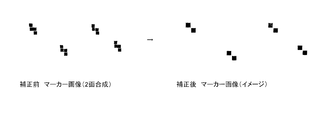
- FIG. 4 illustrates a difference between marker coordinate values obtained from the point cloud data A and the point cloud data B.
- This image is obtained by displaying the point cloud data obtained by the three-dimensional laser light scanning device of the present invention as an image, and displays the point cloud data A and the point cloud data B without stratification.
- the left half of FIG. 4 shows a magnified portion of the measurement of the four checkered markers without applying the mechanical error parameter. It can be seen that the marker coordinates of the point cloud data A and the point cloud data B are displayed two times shifted in the vertical direction.
- the right half of FIG. 4 shows point cloud data corrected by applying an appropriate machine error parameter to the same point cloud data, and the marker coordinate values of point cloud data A and point cloud data B match. Are displayed overlapping. That is, as a result of correcting the point cloud data A and the point cloud data B by the respective mechanical error parameters, the marker coordinate values are matched.
- FIG. 5 shows an example of the aforementioned mechanical error parameter.
- the mechanical error parameters include at least the Z-phase shift of the reflection mirror 2, the angle error, the correction of the tilt angle or the tilt direction, the tilt angle or tilt direction of the laser measurement unit 1, and the tilt of the laser optical axis. Includes angle or tilt direction correction.
- mechanical error parameters correction of the tilt angle or tilt direction of the optical axis of the laser measurement unit 1, phase shift of the mirror encoder 4, correction of the eccentricity or eccentric direction of the disk, phase shift of the spindle encoder 9, correction of the eccentricity or eccentric direction of the disk
- mechanical error parameters such as the position of the reflection point of the reflection mirror 2 (in the X, Y, and Z directions).
- the relationship between the rotational speeds of the mirror drive motor 3 and the spindle drive motor 7 is reversed (mirror drive motor 7). (When the rotation of the motor 3 is slow and the rotation of the spindle drive motor 7 is fast). In this case, the above-mentioned “the lower one of the horizontal rotation speed and the vertical rotation speed in the direction in which the reflection mirror 2 reflects the laser light” is the vertical rotation.
- a plurality of markers are set in the horizontal direction and the vertical direction. Practically, the number of markers is desirably five or more.
- a function capable of calculating a mechanical error parameter can be mounted on the main body of the three-dimensional laser light scanning device, or software having similar functions can be provided to the user. Thereby, the user can easily calibrate the measurement data by using the three-dimensional laser light scanning device and improve the measurement accuracy.
Landscapes
- Physics & Mathematics (AREA)
- General Physics & Mathematics (AREA)
- Engineering & Computer Science (AREA)
- Radar, Positioning & Navigation (AREA)
- Remote Sensing (AREA)
- Electromagnetism (AREA)
- Optics & Photonics (AREA)
- Measurement Of Optical Distance (AREA)
- Mechanical Optical Scanning Systems (AREA)
- Length Measuring Devices By Optical Means (AREA)
Abstract
L'invention concerne un procédé de correction de données de mesure pour un dispositif de balayage à lumière laser tridimensionnel permettant d'améliorer la précision de mesure par simple étalonnage dudit dispositif par un utilisateur. Selon l'invention : des données de nuage de points, obtenues pendant le temps nécessaire à une rotation complète à la vitesse de rotation horizontale ou verticale la plus lente d'un miroir de réflexion (2) d'une unité de mesure laser (1) dans le sens dans lequel est réfléchie la lumière laser par le miroir de réflexion, sont divisées en deux couches constituées de données de nuage de points A et de données de nuage de points B ; un paramètre d'erreur mécanique déterminé est sélectionné ; ledit paramètre est appliqué à des données de nuage de points A et à des données de nuage de points B; des valeurs de coordonnées de marqueur sont obtenues à partir de données de nuage de points A et de données de nuage de points B, puis comparées ; et une valeur de correction de paramètre d'erreur mécanique constituant une différence de valeurs de coordonnées inférieure ou égale à un seuil déterminé est calculée.
Applications Claiming Priority (2)
| Application Number | Priority Date | Filing Date | Title |
|---|---|---|---|
| JP2018-172115 | 2018-09-14 | ||
| JP2018172115A JP2020046187A (ja) | 2018-09-14 | 2018-09-14 | 三次元レーザー光走査装置の計測データ較正方法 |
Publications (1)
| Publication Number | Publication Date |
|---|---|
| WO2020054094A1 true WO2020054094A1 (fr) | 2020-03-19 |
Family
ID=69776509
Family Applications (1)
| Application Number | Title | Priority Date | Filing Date |
|---|---|---|---|
| PCT/JP2019/005776 Ceased WO2020054094A1 (fr) | 2018-09-14 | 2019-02-18 | Procédé de correction de données de mesure pour dispositif de balayage à lumière laser tridimensionnel |
Country Status (2)
| Country | Link |
|---|---|
| JP (1) | JP2020046187A (fr) |
| WO (1) | WO2020054094A1 (fr) |
Cited By (1)
| Publication number | Priority date | Publication date | Assignee | Title |
|---|---|---|---|---|
| CN113124774A (zh) * | 2021-04-08 | 2021-07-16 | 西安应用光学研究所 | 一种曲面镜面形误差直接测量及三维面形扫描系统 |
Families Citing this family (1)
| Publication number | Priority date | Publication date | Assignee | Title |
|---|---|---|---|---|
| CN113551612A (zh) * | 2021-06-18 | 2021-10-26 | 中广核检测技术有限公司 | 一种crdm热套管磨损量测量装置 |
Citations (5)
| Publication number | Priority date | Publication date | Assignee | Title |
|---|---|---|---|---|
| JPH07146121A (ja) * | 1993-10-01 | 1995-06-06 | Nippondenso Co Ltd | 視覚に基く三次元位置および姿勢の認識方法ならびに視覚に基く三次元位置および姿勢の認識装置 |
| JP2008082782A (ja) * | 2006-09-26 | 2008-04-10 | Topcon Corp | レーザスキャナ |
| WO2013128265A2 (fr) * | 2012-03-01 | 2013-09-06 | Trimble A.B. | Procédés et appareil de traitement de données de nuage de points |
| JP2017198555A (ja) * | 2016-04-27 | 2017-11-02 | 富士通株式会社 | 情報処理装置、キャリブレーション方法、およびキャリブレーションプログラム |
| JP2018054408A (ja) * | 2016-09-28 | 2018-04-05 | 株式会社トプコン | 測量装置 |
-
2018
- 2018-09-14 JP JP2018172115A patent/JP2020046187A/ja active Pending
-
2019
- 2019-02-18 WO PCT/JP2019/005776 patent/WO2020054094A1/fr not_active Ceased
Patent Citations (5)
| Publication number | Priority date | Publication date | Assignee | Title |
|---|---|---|---|---|
| JPH07146121A (ja) * | 1993-10-01 | 1995-06-06 | Nippondenso Co Ltd | 視覚に基く三次元位置および姿勢の認識方法ならびに視覚に基く三次元位置および姿勢の認識装置 |
| JP2008082782A (ja) * | 2006-09-26 | 2008-04-10 | Topcon Corp | レーザスキャナ |
| WO2013128265A2 (fr) * | 2012-03-01 | 2013-09-06 | Trimble A.B. | Procédés et appareil de traitement de données de nuage de points |
| JP2017198555A (ja) * | 2016-04-27 | 2017-11-02 | 富士通株式会社 | 情報処理装置、キャリブレーション方法、およびキャリブレーションプログラム |
| JP2018054408A (ja) * | 2016-09-28 | 2018-04-05 | 株式会社トプコン | 測量装置 |
Cited By (2)
| Publication number | Priority date | Publication date | Assignee | Title |
|---|---|---|---|---|
| CN113124774A (zh) * | 2021-04-08 | 2021-07-16 | 西安应用光学研究所 | 一种曲面镜面形误差直接测量及三维面形扫描系统 |
| CN113124774B (zh) * | 2021-04-08 | 2023-03-28 | 西安应用光学研究所 | 一种曲面镜面形误差直接测量及三维面形扫描系统 |
Also Published As
| Publication number | Publication date |
|---|---|
| JP2020046187A (ja) | 2020-03-26 |
Similar Documents
| Publication | Publication Date | Title |
|---|---|---|
| US9383198B2 (en) | Method and device for reducing errors in a turning device during the determination of coordinates of a workpiece or during the machining of a workpiece | |
| JP6385463B2 (ja) | 物体の幾何学的な計測装置および方法 | |
| CN106873122B (zh) | 一种用于大口径非球面反射镜定心装调的装置及方法 | |
| JP5681715B2 (ja) | 環境を光学的に走査および測定する方法 | |
| JP2005326402A (ja) | 球形及び近似球形光学表面の形状の計測 | |
| US20150260859A1 (en) | Method and device for correcting computed tomographiy measurements, comprising a coordinate measuring machine | |
| JP2022153541A (ja) | 測量装置、測量方法およびプログラム | |
| CN110246191B (zh) | 相机非参数模型标定方法及标定精度评估方法 | |
| CN106813594B (zh) | 大口径掠入射反射聚焦镜高精度面形检测方法 | |
| EP2395317A1 (fr) | Appareil de mesure par l'interférence des ondes lumineuses | |
| CN108151668A (zh) | 一种叶片型面全数据测量拼接方法及装置 | |
| CN113932741B (zh) | X射线测量装置的校准方法 | |
| WO2020054094A1 (fr) | Procédé de correction de données de mesure pour dispositif de balayage à lumière laser tridimensionnel | |
| JP6709471B2 (ja) | 三次元レーザー光走査装置 | |
| TW561241B (en) | Method and apparatus for calibrating laser three-dimensional digitizing sensor | |
| WO2020156413A1 (fr) | Dispositif à laser rotatif et procédé de télémétrie par laser | |
| EP3954966A1 (fr) | Compensation de table rotative | |
| WO2007043974A1 (fr) | Système et procédé de tomodensitométrie | |
| JP6105518B2 (ja) | 三次元駆動装置 | |
| CN102809346B (zh) | 运动平台的位置测量装置及其测量方法 | |
| US6160616A (en) | Laser system | |
| CN110954022B (zh) | 一种圆环形物体旋转扫描结构以及标定方法 | |
| JP2014085189A (ja) | 測定装置 | |
| CN112731288A (zh) | 线结构激光面的非参数模型标定方法及其标定装置 | |
| TWI785914B (zh) | 雙旋轉軸的幾何誤差的獲取方法與獲取設備 |
Legal Events
| Date | Code | Title | Description |
|---|---|---|---|
| 121 | Ep: the epo has been informed by wipo that ep was designated in this application |
Ref document number: 19860011 Country of ref document: EP Kind code of ref document: A1 |
|
| NENP | Non-entry into the national phase |
Ref country code: DE |
|
| 122 | Ep: pct application non-entry in european phase |
Ref document number: 19860011 Country of ref document: EP Kind code of ref document: A1 |