WO2020054215A1 - 接合用発熱回路、接合体、接合用発熱回路の製造方法及び接合方法 - Google Patents
接合用発熱回路、接合体、接合用発熱回路の製造方法及び接合方法 Download PDFInfo
- Publication number
- WO2020054215A1 WO2020054215A1 PCT/JP2019/028305 JP2019028305W WO2020054215A1 WO 2020054215 A1 WO2020054215 A1 WO 2020054215A1 JP 2019028305 W JP2019028305 W JP 2019028305W WO 2020054215 A1 WO2020054215 A1 WO 2020054215A1
- Authority
- WO
- WIPO (PCT)
- Prior art keywords
- circuit
- members
- bonding
- heating
- joining
- Prior art date
- Legal status (The legal status is an assumption and is not a legal conclusion. Google has not performed a legal analysis and makes no representation as to the accuracy of the status listed.)
- Ceased
Links
Images




Classifications
-
- B—PERFORMING OPERATIONS; TRANSPORTING
- B29—WORKING OF PLASTICS; WORKING OF SUBSTANCES IN A PLASTIC STATE IN GENERAL
- B29C—SHAPING OR JOINING OF PLASTICS; SHAPING OF MATERIAL IN A PLASTIC STATE, NOT OTHERWISE PROVIDED FOR; AFTER-TREATMENT OF THE SHAPED PRODUCTS, e.g. REPAIRING
- B29C65/00—Joining or sealing of preformed parts, e.g. welding of plastics materials; Apparatus therefor
- B29C65/02—Joining or sealing of preformed parts, e.g. welding of plastics materials; Apparatus therefor by heating, with or without pressure
- B29C65/34—Joining or sealing of preformed parts, e.g. welding of plastics materials; Apparatus therefor by heating, with or without pressure using heated elements which remain in the joint, e.g. "verlorenes Schweisselement"
- B29C65/3404—Joining or sealing of preformed parts, e.g. welding of plastics materials; Apparatus therefor by heating, with or without pressure using heated elements which remain in the joint, e.g. "verlorenes Schweisselement" characterised by the type of heated elements which remain in the joint
-
- B—PERFORMING OPERATIONS; TRANSPORTING
- B22—CASTING; POWDER METALLURGY
- B22F—WORKING METALLIC POWDER; MANUFACTURE OF ARTICLES FROM METALLIC POWDER; MAKING METALLIC POWDER; APPARATUS OR DEVICES SPECIALLY ADAPTED FOR METALLIC POWDER
- B22F10/00—Additive manufacturing of workpieces or articles from metallic powder
- B22F10/10—Formation of a green body
-
- B—PERFORMING OPERATIONS; TRANSPORTING
- B22—CASTING; POWDER METALLURGY
- B22F—WORKING METALLIC POWDER; MANUFACTURE OF ARTICLES FROM METALLIC POWDER; MAKING METALLIC POWDER; APPARATUS OR DEVICES SPECIALLY ADAPTED FOR METALLIC POWDER
- B22F5/00—Manufacture of workpieces or articles from metallic powder characterised by the special shape of the product
- B22F5/12—Manufacture of workpieces or articles from metallic powder characterised by the special shape of the product of wires
-
- B—PERFORMING OPERATIONS; TRANSPORTING
- B22—CASTING; POWDER METALLURGY
- B22F—WORKING METALLIC POWDER; MANUFACTURE OF ARTICLES FROM METALLIC POWDER; MAKING METALLIC POWDER; APPARATUS OR DEVICES SPECIALLY ADAPTED FOR METALLIC POWDER
- B22F7/00—Manufacture of composite layers, workpieces, or articles, comprising metallic powder, by sintering the powder, with or without compacting wherein at least one part is obtained by sintering or compression
- B22F7/06—Manufacture of composite layers, workpieces, or articles, comprising metallic powder, by sintering the powder, with or without compacting wherein at least one part is obtained by sintering or compression of composite workpieces or articles from parts, e.g. to form tipped tools
- B22F7/062—Manufacture of composite layers, workpieces, or articles, comprising metallic powder, by sintering the powder, with or without compacting wherein at least one part is obtained by sintering or compression of composite workpieces or articles from parts, e.g. to form tipped tools involving the connection or repairing of preformed parts
-
- B—PERFORMING OPERATIONS; TRANSPORTING
- B22—CASTING; POWDER METALLURGY
- B22F—WORKING METALLIC POWDER; MANUFACTURE OF ARTICLES FROM METALLIC POWDER; MAKING METALLIC POWDER; APPARATUS OR DEVICES SPECIALLY ADAPTED FOR METALLIC POWDER
- B22F7/00—Manufacture of composite layers, workpieces, or articles, comprising metallic powder, by sintering the powder, with or without compacting wherein at least one part is obtained by sintering or compression
- B22F7/06—Manufacture of composite layers, workpieces, or articles, comprising metallic powder, by sintering the powder, with or without compacting wherein at least one part is obtained by sintering or compression of composite workpieces or articles from parts, e.g. to form tipped tools
- B22F7/08—Manufacture of composite layers, workpieces, or articles, comprising metallic powder, by sintering the powder, with or without compacting wherein at least one part is obtained by sintering or compression of composite workpieces or articles from parts, e.g. to form tipped tools with one or more parts not made from powder
-
- B—PERFORMING OPERATIONS; TRANSPORTING
- B29—WORKING OF PLASTICS; WORKING OF SUBSTANCES IN A PLASTIC STATE IN GENERAL
- B29C—SHAPING OR JOINING OF PLASTICS; SHAPING OF MATERIAL IN A PLASTIC STATE, NOT OTHERWISE PROVIDED FOR; AFTER-TREATMENT OF THE SHAPED PRODUCTS, e.g. REPAIRING
- B29C65/00—Joining or sealing of preformed parts, e.g. welding of plastics materials; Apparatus therefor
- B29C65/02—Joining or sealing of preformed parts, e.g. welding of plastics materials; Apparatus therefor by heating, with or without pressure
- B29C65/34—Joining or sealing of preformed parts, e.g. welding of plastics materials; Apparatus therefor by heating, with or without pressure using heated elements which remain in the joint, e.g. "verlorenes Schweisselement"
- B29C65/3404—Joining or sealing of preformed parts, e.g. welding of plastics materials; Apparatus therefor by heating, with or without pressure using heated elements which remain in the joint, e.g. "verlorenes Schweisselement" characterised by the type of heated elements which remain in the joint
- B29C65/342—Joining or sealing of preformed parts, e.g. welding of plastics materials; Apparatus therefor by heating, with or without pressure using heated elements which remain in the joint, e.g. "verlorenes Schweisselement" characterised by the type of heated elements which remain in the joint comprising at least a single wire, e.g. in the form of a winding
- B29C65/3428—Joining or sealing of preformed parts, e.g. welding of plastics materials; Apparatus therefor by heating, with or without pressure using heated elements which remain in the joint, e.g. "verlorenes Schweisselement" characterised by the type of heated elements which remain in the joint comprising at least a single wire, e.g. in the form of a winding said at least a single wire having a waveform, e.g. a sinusoidal form
-
- B—PERFORMING OPERATIONS; TRANSPORTING
- B29—WORKING OF PLASTICS; WORKING OF SUBSTANCES IN A PLASTIC STATE IN GENERAL
- B29C—SHAPING OR JOINING OF PLASTICS; SHAPING OF MATERIAL IN A PLASTIC STATE, NOT OTHERWISE PROVIDED FOR; AFTER-TREATMENT OF THE SHAPED PRODUCTS, e.g. REPAIRING
- B29C65/00—Joining or sealing of preformed parts, e.g. welding of plastics materials; Apparatus therefor
- B29C65/02—Joining or sealing of preformed parts, e.g. welding of plastics materials; Apparatus therefor by heating, with or without pressure
- B29C65/34—Joining or sealing of preformed parts, e.g. welding of plastics materials; Apparatus therefor by heating, with or without pressure using heated elements which remain in the joint, e.g. "verlorenes Schweisselement"
- B29C65/3472—Joining or sealing of preformed parts, e.g. welding of plastics materials; Apparatus therefor by heating, with or without pressure using heated elements which remain in the joint, e.g. "verlorenes Schweisselement" characterised by the composition of the heated elements which remain in the joint
- B29C65/3476—Joining or sealing of preformed parts, e.g. welding of plastics materials; Apparatus therefor by heating, with or without pressure using heated elements which remain in the joint, e.g. "verlorenes Schweisselement" characterised by the composition of the heated elements which remain in the joint being metallic
-
- B—PERFORMING OPERATIONS; TRANSPORTING
- B29—WORKING OF PLASTICS; WORKING OF SUBSTANCES IN A PLASTIC STATE IN GENERAL
- B29C—SHAPING OR JOINING OF PLASTICS; SHAPING OF MATERIAL IN A PLASTIC STATE, NOT OTHERWISE PROVIDED FOR; AFTER-TREATMENT OF THE SHAPED PRODUCTS, e.g. REPAIRING
- B29C66/00—General aspects of processes or apparatus for joining preformed parts
- B29C66/01—General aspects dealing with the joint area or with the area to be joined
- B29C66/05—Particular design of joint configurations
- B29C66/10—Particular design of joint configurations particular design of the joint cross-sections
- B29C66/11—Joint cross-sections comprising a single joint-segment, i.e. one of the parts to be joined comprising a single joint-segment in the joint cross-section
- B29C66/112—Single lapped joints
- B29C66/1122—Single lap to lap joints, i.e. overlap joints
-
- B—PERFORMING OPERATIONS; TRANSPORTING
- B29—WORKING OF PLASTICS; WORKING OF SUBSTANCES IN A PLASTIC STATE IN GENERAL
- B29C—SHAPING OR JOINING OF PLASTICS; SHAPING OF MATERIAL IN A PLASTIC STATE, NOT OTHERWISE PROVIDED FOR; AFTER-TREATMENT OF THE SHAPED PRODUCTS, e.g. REPAIRING
- B29C66/00—General aspects of processes or apparatus for joining preformed parts
- B29C66/01—General aspects dealing with the joint area or with the area to be joined
- B29C66/05—Particular design of joint configurations
- B29C66/303—Particular design of joint configurations the joint involving an anchoring effect
- B29C66/3034—Particular design of joint configurations the joint involving an anchoring effect making use of additional elements, e.g. meshes
- B29C66/30341—Particular design of joint configurations the joint involving an anchoring effect making use of additional elements, e.g. meshes non-integral with the parts to be joined, e.g. making use of extra elements
-
- B—PERFORMING OPERATIONS; TRANSPORTING
- B29—WORKING OF PLASTICS; WORKING OF SUBSTANCES IN A PLASTIC STATE IN GENERAL
- B29C—SHAPING OR JOINING OF PLASTICS; SHAPING OF MATERIAL IN A PLASTIC STATE, NOT OTHERWISE PROVIDED FOR; AFTER-TREATMENT OF THE SHAPED PRODUCTS, e.g. REPAIRING
- B29C66/00—General aspects of processes or apparatus for joining preformed parts
- B29C66/40—General aspects of joining substantially flat articles, e.g. plates, sheets or web-like materials; Making flat seams in tubular or hollow articles; Joining single elements to substantially flat surfaces
- B29C66/41—Joining substantially flat articles ; Making flat seams in tubular or hollow articles
- B29C66/45—Joining of substantially the whole surface of the articles
-
- B—PERFORMING OPERATIONS; TRANSPORTING
- B29—WORKING OF PLASTICS; WORKING OF SUBSTANCES IN A PLASTIC STATE IN GENERAL
- B29C—SHAPING OR JOINING OF PLASTICS; SHAPING OF MATERIAL IN A PLASTIC STATE, NOT OTHERWISE PROVIDED FOR; AFTER-TREATMENT OF THE SHAPED PRODUCTS, e.g. REPAIRING
- B29C66/00—General aspects of processes or apparatus for joining preformed parts
- B29C66/70—General aspects of processes or apparatus for joining preformed parts characterised by the composition, physical properties or the structure of the material of the parts to be joined; Joining with non-plastics material
- B29C66/72—General aspects of processes or apparatus for joining preformed parts characterised by the composition, physical properties or the structure of the material of the parts to be joined; Joining with non-plastics material characterised by the structure of the material of the parts to be joined
- B29C66/721—Fibre-reinforced materials
- B29C66/7212—Fibre-reinforced materials characterised by the composition of the fibres
-
- B—PERFORMING OPERATIONS; TRANSPORTING
- B29—WORKING OF PLASTICS; WORKING OF SUBSTANCES IN A PLASTIC STATE IN GENERAL
- B29C—SHAPING OR JOINING OF PLASTICS; SHAPING OF MATERIAL IN A PLASTIC STATE, NOT OTHERWISE PROVIDED FOR; AFTER-TREATMENT OF THE SHAPED PRODUCTS, e.g. REPAIRING
- B29C66/00—General aspects of processes or apparatus for joining preformed parts
- B29C66/70—General aspects of processes or apparatus for joining preformed parts characterised by the composition, physical properties or the structure of the material of the parts to be joined; Joining with non-plastics material
- B29C66/72—General aspects of processes or apparatus for joining preformed parts characterised by the composition, physical properties or the structure of the material of the parts to be joined; Joining with non-plastics material characterised by the structure of the material of the parts to be joined
- B29C66/721—Fibre-reinforced materials
- B29C66/7214—Fibre-reinforced materials characterised by the length of the fibres
- B29C66/72141—Fibres of continuous length
-
- B—PERFORMING OPERATIONS; TRANSPORTING
- B29—WORKING OF PLASTICS; WORKING OF SUBSTANCES IN A PLASTIC STATE IN GENERAL
- B29C—SHAPING OR JOINING OF PLASTICS; SHAPING OF MATERIAL IN A PLASTIC STATE, NOT OTHERWISE PROVIDED FOR; AFTER-TREATMENT OF THE SHAPED PRODUCTS, e.g. REPAIRING
- B29C66/00—General aspects of processes or apparatus for joining preformed parts
- B29C66/70—General aspects of processes or apparatus for joining preformed parts characterised by the composition, physical properties or the structure of the material of the parts to be joined; Joining with non-plastics material
- B29C66/73—General aspects of processes or apparatus for joining preformed parts characterised by the composition, physical properties or the structure of the material of the parts to be joined; Joining with non-plastics material characterised by the intensive physical properties of the material of the parts to be joined, by the optical properties of the material of the parts to be joined, by the extensive physical properties of the parts to be joined, by the state of the material of the parts to be joined or by the material of the parts to be joined being a thermoplastic or a thermoset
- B29C66/739—General aspects of processes or apparatus for joining preformed parts characterised by the composition, physical properties or the structure of the material of the parts to be joined; Joining with non-plastics material characterised by the intensive physical properties of the material of the parts to be joined, by the optical properties of the material of the parts to be joined, by the extensive physical properties of the parts to be joined, by the state of the material of the parts to be joined or by the material of the parts to be joined being a thermoplastic or a thermoset characterised by the material of the parts to be joined being a thermoplastic or a thermoset
- B29C66/7392—General aspects of processes or apparatus for joining preformed parts characterised by the composition, physical properties or the structure of the material of the parts to be joined; Joining with non-plastics material characterised by the intensive physical properties of the material of the parts to be joined, by the optical properties of the material of the parts to be joined, by the extensive physical properties of the parts to be joined, by the state of the material of the parts to be joined or by the material of the parts to be joined being a thermoplastic or a thermoset characterised by the material of the parts to be joined being a thermoplastic or a thermoset characterised by the material of at least one of the parts being a thermoplastic
- B29C66/73921—General aspects of processes or apparatus for joining preformed parts characterised by the composition, physical properties or the structure of the material of the parts to be joined; Joining with non-plastics material characterised by the intensive physical properties of the material of the parts to be joined, by the optical properties of the material of the parts to be joined, by the extensive physical properties of the parts to be joined, by the state of the material of the parts to be joined or by the material of the parts to be joined being a thermoplastic or a thermoset characterised by the material of the parts to be joined being a thermoplastic or a thermoset characterised by the material of at least one of the parts being a thermoplastic characterised by the materials of both parts being thermoplastics
-
- B—PERFORMING OPERATIONS; TRANSPORTING
- B29—WORKING OF PLASTICS; WORKING OF SUBSTANCES IN A PLASTIC STATE IN GENERAL
- B29C—SHAPING OR JOINING OF PLASTICS; SHAPING OF MATERIAL IN A PLASTIC STATE, NOT OTHERWISE PROVIDED FOR; AFTER-TREATMENT OF THE SHAPED PRODUCTS, e.g. REPAIRING
- B29C66/00—General aspects of processes or apparatus for joining preformed parts
- B29C66/80—General aspects of machine operations or constructions and parts thereof
- B29C66/83—General aspects of machine operations or constructions and parts thereof characterised by the movement of the joining or pressing tools
- B29C66/834—General aspects of machine operations or constructions and parts thereof characterised by the movement of the joining or pressing tools moving with the parts to be joined
- B29C66/8341—Roller, cylinder or drum types; Band or belt types; Ball types
- B29C66/83411—Roller, cylinder or drum types
- B29C66/83413—Roller, cylinder or drum types cooperating rollers, cylinders or drums
-
- B—PERFORMING OPERATIONS; TRANSPORTING
- B33—ADDITIVE MANUFACTURING TECHNOLOGY
- B33Y—ADDITIVE MANUFACTURING, i.e. MANUFACTURING OF THREE-DIMENSIONAL [3D] OBJECTS BY ADDITIVE DEPOSITION, ADDITIVE AGGLOMERATION OR ADDITIVE LAYERING, e.g. BY 3D PRINTING, STEREOLITHOGRAPHY OR SELECTIVE LASER SINTERING
- B33Y80/00—Products made by additive manufacturing
-
- H—ELECTRICITY
- H05—ELECTRIC TECHNIQUES NOT OTHERWISE PROVIDED FOR
- H05B—ELECTRIC HEATING; ELECTRIC LIGHT SOURCES NOT OTHERWISE PROVIDED FOR; CIRCUIT ARRANGEMENTS FOR ELECTRIC LIGHT SOURCES, IN GENERAL
- H05B3/00—Ohmic-resistance heating
- H05B3/20—Heating elements having extended surface area substantially in a two-dimensional [2D] plane, e.g. plate-heater
- H05B3/34—Heating elements having extended surface area substantially in a two-dimensional [2D] plane, e.g. plate-heater flexible, e.g. heating nets or webs
-
- B—PERFORMING OPERATIONS; TRANSPORTING
- B22—CASTING; POWDER METALLURGY
- B22F—WORKING METALLIC POWDER; MANUFACTURE OF ARTICLES FROM METALLIC POWDER; MAKING METALLIC POWDER; APPARATUS OR DEVICES SPECIALLY ADAPTED FOR METALLIC POWDER
- B22F2999/00—Aspects linked to processes or compositions used in powder metallurgy
-
- B—PERFORMING OPERATIONS; TRANSPORTING
- B29—WORKING OF PLASTICS; WORKING OF SUBSTANCES IN A PLASTIC STATE IN GENERAL
- B29K—INDEXING SCHEME ASSOCIATED WITH SUBCLASSES B29B, B29C OR B29D, RELATING TO MOULDING MATERIALS OR TO MATERIALS FOR MOULDS, REINFORCEMENTS, FILLERS OR PREFORMED PARTS, e.g. INSERTS
- B29K2307/00—Use of elements other than metals as reinforcement
- B29K2307/04—Carbon
-
- H—ELECTRICITY
- H05—ELECTRIC TECHNIQUES NOT OTHERWISE PROVIDED FOR
- H05B—ELECTRIC HEATING; ELECTRIC LIGHT SOURCES NOT OTHERWISE PROVIDED FOR; CIRCUIT ARRANGEMENTS FOR ELECTRIC LIGHT SOURCES, IN GENERAL
- H05B2203/00—Aspects relating to Ohmic resistive heating covered by group H05B3/00
- H05B2203/002—Heaters using a particular layout for the resistive material or resistive elements
- H05B2203/003—Heaters using a particular layout for the resistive material or resistive elements using serpentine layout
-
- H—ELECTRICITY
- H05—ELECTRIC TECHNIQUES NOT OTHERWISE PROVIDED FOR
- H05B—ELECTRIC HEATING; ELECTRIC LIGHT SOURCES NOT OTHERWISE PROVIDED FOR; CIRCUIT ARRANGEMENTS FOR ELECTRIC LIGHT SOURCES, IN GENERAL
- H05B2203/00—Aspects relating to Ohmic resistive heating covered by group H05B3/00
- H05B2203/013—Heaters using resistive films or coatings
-
- H—ELECTRICITY
- H05—ELECTRIC TECHNIQUES NOT OTHERWISE PROVIDED FOR
- H05B—ELECTRIC HEATING; ELECTRIC LIGHT SOURCES NOT OTHERWISE PROVIDED FOR; CIRCUIT ARRANGEMENTS FOR ELECTRIC LIGHT SOURCES, IN GENERAL
- H05B2203/00—Aspects relating to Ohmic resistive heating covered by group H05B3/00
- H05B2203/014—Heaters using resistive wires or cables not provided for in H05B3/54
-
- H—ELECTRICITY
- H05—ELECTRIC TECHNIQUES NOT OTHERWISE PROVIDED FOR
- H05B—ELECTRIC HEATING; ELECTRIC LIGHT SOURCES NOT OTHERWISE PROVIDED FOR; CIRCUIT ARRANGEMENTS FOR ELECTRIC LIGHT SOURCES, IN GENERAL
- H05B2203/00—Aspects relating to Ohmic resistive heating covered by group H05B3/00
- H05B2203/017—Manufacturing methods or apparatus for heaters
-
- H—ELECTRICITY
- H05—ELECTRIC TECHNIQUES NOT OTHERWISE PROVIDED FOR
- H05B—ELECTRIC HEATING; ELECTRIC LIGHT SOURCES NOT OTHERWISE PROVIDED FOR; CIRCUIT ARRANGEMENTS FOR ELECTRIC LIGHT SOURCES, IN GENERAL
- H05B2203/00—Aspects relating to Ohmic resistive heating covered by group H05B3/00
- H05B2203/035—Electrical circuits used in resistive heating apparatus
-
- Y—GENERAL TAGGING OF NEW TECHNOLOGICAL DEVELOPMENTS; GENERAL TAGGING OF CROSS-SECTIONAL TECHNOLOGIES SPANNING OVER SEVERAL SECTIONS OF THE IPC; TECHNICAL SUBJECTS COVERED BY FORMER USPC CROSS-REFERENCE ART COLLECTIONS [XRACs] AND DIGESTS
- Y02—TECHNOLOGIES OR APPLICATIONS FOR MITIGATION OR ADAPTATION AGAINST CLIMATE CHANGE
- Y02P—CLIMATE CHANGE MITIGATION TECHNOLOGIES IN THE PRODUCTION OR PROCESSING OF GOODS
- Y02P10/00—Technologies related to metal processing
- Y02P10/25—Process efficiency
Definitions
- the present invention relates to a heating circuit for bonding, a joined body, a method for manufacturing a heating circuit for bonding, and a bonding method.
- a resistance heating element arranged between a pair of joining members has been known as a heating circuit for joining (for example, see Patent Document 1).
- the joining member is a fiber reinforced thermoplastic resin member, and the resistance heating element fuses the pair of joining members by being energized between the pair of joining members.
- the heat generating circuit for bonding such as the resistance heat generating element needs to be densely arranged because it is necessary to uniformly heat the fused portion.
- the heating circuits for bonding are densely arranged, the heating circuits for bonding cannot move within the molten resin before curing and move after the resin is melted. Doing so may cause a short circuit. Further, after the fusion is completed, the heat generating circuit for bonding is left on the fusion surface, so that the fusion strength may be reduced.
- the heating circuit for bonding of the present invention in the heating circuit for bonding arranged between the members, a heating wire, and a plurality of protrusions projecting from the heating wire along a facing direction in which the members face each other, It is characterized by having.
- the protrusion serves as a resistance to the member having fluidity before hardening, and the heating circuit for bonding is less likely to flow, it is possible to suppress occurrence of a short circuit due to contact between the circuits.
- the protrusion bites into the member before curing, the joining strength between the members can be improved.
- the projecting direction of the protrusion along the facing direction is, for example, a direction perpendicular to the fusion surface where the member melts, but is not necessarily perpendicular, and is perpendicular to the fusion surface. Any direction including a component of the direction may be used.
- the lengths of the plurality of protrusions in the protruding direction may be the same length or may be different lengths.
- the length of the projection in the protruding direction is at least half the thickness of the fusion layer in which the member melts.
- the protrusions can be appropriately cut into the fusion layer, so that the flow of the resistance fusion circuit can be appropriately suppressed, and the members can be appropriately fused. Can be worn.
- the protrusion is made of a material having higher thermal conductivity than the heating wire.
- the member in contact with the protrusion can be melted suitably.
- the interval between the adjacent protrusions is longer than the length of the protrusion in the protrusion direction.
- the apparatus further comprises a film covering the heating wire and the protrusion, and the film is preferably made of the same material as the member.
- the heating wire and the protruding portion can be arranged between the members while being protected by the film. Further, since the film is made of the same material as the member, the member to be joined and the film can be suitably integrated. In addition, a thermoplastic resin is applied to the film, for example.
- Another heating circuit for bonding of the present invention is a heating circuit for bonding arranged between members, comprising a sheet-shaped electrotroph extending in the elongate direction, wherein the electrotroph extends in the elongate direction. It is characterized by being formed by being twisted as an axial direction.
- the tropics can be formed into a three-dimensional shape by twisting the tropics.
- the three-dimensionally formed electrotroph is less likely to flow with respect to a member having fluidity before hardening, so that occurrence of a short circuit due to contact between circuits can be suppressed.
- the three-dimensionally shaped electrotroph bites into the melted member, the joining strength between the members can be improved.
- a joined body of the present invention includes the above-described heating circuit for joining, and members provided on both sides of the heating circuit for joining.
- the method for manufacturing a heat generating circuit for bonding is a method for manufacturing a heat generating circuit for bonding for manufacturing a heat generating circuit for bonding disposed between members, wherein the heat generating circuit for bonding includes: a heating wire; A plurality of protrusions projecting from the heating wire along the facing direction in which the heating wire is discharged from the discharge head toward the molding table, and the heating wire and the plurality of And a shaping step of shaping the protrusion.
- the heating wire for bonding can be easily formed by forming the heating wire and the plurality of protrusions with the conductive ink ejected from the ejection head.
- Another method of manufacturing a heat generating circuit for bonding is a method of manufacturing a heat generating circuit for bonding which uses a base material to manufacture a heat generating circuit for bonding arranged between members, wherein the heat generating circuit for bonding is A heating wire, and a plurality of protrusions projecting from the heating wire along an opposing direction in which the members oppose each other, and a resist is formed at a position where the plurality of protrusions on the base material are formed.
- a resist applying step of applying, an etching step of etching the base material coated with the resist, and a resist removing step of removing the resist applied to the base material after the etching to form the bonding heat generating circuit And the following.
- the shapes of the heating wire and the plurality of protrusions can be formed with high accuracy.
- Another method of manufacturing a heat generating circuit for bonding is a method of manufacturing a heat generating circuit for bonding which uses a base material to manufacture a heat generating circuit for bonding arranged between members, wherein the heat generating circuit for bonding is A heating wire, and a plurality of protrusions protruding from the heating wire along an opposing direction in which the members face each other, and a punch roller that sandwiches the base material, the heating wire, A cut portion for cutting out, and a non-cut portion in which a cut is not formed at a position where the protrusion is formed, and forming the non-cut portion when releasing the heating wire from the base material.
- a punching step is provided in which the projection is projected from the heating wire so that the projection is in the facing direction by tearing.
- the plurality of protrusions can be made to protrude in the facing direction, so that the heating circuit for bonding can be easily formed.
- a joining heat generating circuit is arranged between members, and in the joining method of joining the members, a plurality of protrusions projecting along a facing direction in which the members face each other.
- a plurality of formed heating wires are arranged on the member, and the heating wires are connected to each other by a current-carrying member to form a heat generating circuit for joining; and on the formed heat generating circuit for joining,
- the members can be joined together after the joining heat generating circuit is formed on the members.
- the joining heat generating circuit is connected by a current-carrying member so that a plurality of heating wires form a series or parallel circuit.
- a joining heat generating circuit in which a joining heat generating circuit is arranged between members and the members are joined to each other, a plurality of members projecting along a facing direction in which the members face each other.
- Forming a heating circuit for bonding by heating the heating wire on which the protrusions are formed and arranging the heating wire on the member so that the heating wire has a predetermined circuit pattern.
- the heating wire by disposing the heating wire on the member while heating the heating wire and the protruding portion, the protruding portion can be suitably bite into the member. For this reason, the joining heat generating circuit formed on the members can suitably join the members.
- the heating wire is formed so as to have a predetermined circuit pattern.
- the protrusion can be suitably cut into the member.
- the joining heat generating circuit formed on the members can suitably join the members.
- a plurality of protrusions can be formed by increasing the thickness of the conductive material.
- the joining heat generating circuit formed on the member can suitably join the members.
- FIG. 1 is a cross-sectional view schematically illustrating the joined body according to the first embodiment.
- FIG. 2 is a schematic diagram of the resistance fusion circuit according to the first embodiment.
- FIG. 3 is a diagram illustrating an example of the method for manufacturing the resistance fusion-bonded circuit according to the first embodiment.
- FIG. 4 is an explanatory diagram illustrating an example of a method for manufacturing the resistance fusion-bonded circuit according to the first embodiment.
- FIG. 5 is a diagram illustrating an example of the method for manufacturing the resistance fusion-bonded circuit according to the first embodiment.
- FIG. 6 is a plan view schematically illustrating a resistance fusion circuit formed by the method for manufacturing a resistance fusion circuit according to the first embodiment.
- FIG. 7 is a schematic diagram of a resistance fusion circuit according to the second embodiment.
- FIG. 8 is an explanatory diagram relating to a bonding method using the resistance fusion circuit according to the third embodiment.
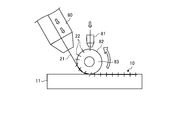
- FIG. 9 is a diagram illustrating a bonding method using the resistance fusion circuit according to the fourth embodiment.
- FIG. 10 is an explanatory diagram relating to a bonding method using the resistance fusion circuit according to the fifth embodiment.
- FIG. 11 is an explanatory diagram relating to a joining method using a resistance fusion circuit according to the sixth embodiment.
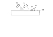
- FIG. 12 is an explanatory diagram relating to a joining method using a resistance fusion circuit according to the seventh embodiment.
- the heating circuit for bonding according to the first embodiment is a heating element used for fusing the members to be bonded 11 to each other, and is a so-called resistance fusion circuit 10.
- a joined body 1 formed using a resistance fusion circuit 10 will be described.
- FIG. 1 is a cross-sectional view schematically illustrating the joined body according to the first embodiment.
- the joined body 1 includes a resistance fusion circuit 10 and two members 11 to be joined provided on both sides of the resistance fusion circuit 10.
- the thickness direction of the resistance fusion circuit 10 and the member 11 to be joined is defined as a Z direction
- a predetermined direction orthogonal to the thickness direction is defined as an X direction
- a direction orthogonal to the Z direction and the X direction is defined as a Y direction.
- the resistance fusion circuit 10 is a thin-film circuit that extends along the fusion surface 12 of the member 11 to be joined.
- the member to be joined 11 is, for example, a composite material in which a carbon fiber 14 is impregnated with a thermoplastic resin 15, a so-called CFRTP (Carbon Fiber Reinforced Thermoplastics).
- CFRTP Carbon Fiber Reinforced Thermoplastics
- any member may be used as long as the member includes a resin that is melted by being heated, and is not particularly limited.
- the present invention will be described by applying to a member to be joined 11 containing a resin that is melted by being heated.
- the first embodiment may be applied to a member to be joined containing a thermosetting resin.
- the present invention may be applied to a composite material in which a thermosetting resin is impregnated into reinforcing fibers such as carbon fibers.
- the heat generating circuit for bonding is a heat generating circuit used for thermosetting the members to be bonded together.
- the joining heat generating circuit may join the members 11 to be joined together by heating and thermally curing the members (composite material) in the semi-cured state.
- the member to be joined including the thermosetting resin may be an adhesive sheet made of a thermosetting resin disposed between the members in addition to the above-described composite material.
- the member 11 and the resistance fusion circuit 10 are connected to each other. Are superimposed in the Z direction. After that, the resistance fusion circuit 10 is energized to generate heat. When the resistance fusion circuit 10 generates heat, the fusion surface 12 of the member 11 to be fused is melted, so that the member 11 to be joined is integrated with the resistance fusion circuit 10. Then, by cooling, the joined members 11 are joined to each other to form the joined body 1.
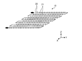
- FIG. 2 is a schematic diagram of the resistance fusion circuit according to the first embodiment.
- the resistance fusion circuit 10 includes a heating wire 21 and a plurality of protrusions 22 protruding from the heating wire.
- the heating wire 21 is a metal wire that generates heat when energized, and has a predetermined wiring pattern in the XY plane.
- the heating wire 21 has a wiring pattern meandering in the X direction while reciprocating in the Y direction, and is formed in a substantially rectangular shape in the XY plane.
- the wiring pattern is not particularly limited.
- the heating wire 21 has a wire diameter that is appropriate in accordance with the melting conditions of the member to be joined 11 and the like.
- the interval between adjacent heating wires 21 is The intervals are appropriate depending on the melting conditions and the like.
- the plurality of protrusions 22 are formed so as to protrude from the heating wire 21 along the facing direction in which the members to be joined 11 face each other, that is, along the Z direction.
- the projection direction of the projection 22 along the Z direction is, for example, a direction perpendicular to the fusion surface 12 where the member 11 is melted, but is not necessarily perpendicular to the fusion surface 12. Any direction may be used as long as it includes a component in a direction perpendicular to.
- the protrusion 22 may have a wedge shape that tapers toward the tip in the protruding direction, or may have an inverted triangular shape in which a stopper that spreads toward the tip in the protruding direction is formed. Is not particularly limited.
- the length of the protrusion 22 in the protruding direction is at least half the thickness of the fusion layer in which the member 11 is melted.
- the fusion layer is a layer having a thickness in the Z direction in which the member to be joined 11 is melted by the resistance fusion circuit 10, and is, for example, a layer from the fusion surface 12 to the carbon fibers.
- the length of the protrusion 22 in the protruding direction is shorter than the distance between the adjacent protrusions 22 on the heating wire 21. In other words, the interval between the adjacent protrusions 22 on the heating wire 21 is longer than the length of the protrusion 22 in the protrusion direction.
- the lengths of the plurality of protrusions 22 in the protruding direction may be the same length or may be different lengths.
- the protrusion 22 may be formed using the same material as the heating wire 21 or may be formed using a different material. When a different material is used, the protrusion 22 is made of a material having higher thermal conductivity than the heating wire 21. For this reason, it is possible to efficiently transfer the heat generated by the heating wire 21 to the protruding portion 22 when the resistance welding circuit 10 is energized.
- the resistance fusion circuit 10 may further include a protective film 23 (see FIG. 3) that covers the heating wire 21 and the protrusion 22.
- a protective film 23 see FIG. 3
- the protective film 23 may be made of a material different from the resin contained in the member 11 to be joined. In this case, when energizing the resistance fusion circuit 10, the protection film 23 may be used with the protection film 23 attached, or the protection film 23 may be peeled off.
- the resin contained in the member to be joined 11 is a thermoplastic resin, that is, the member to be joined 11 is a thermoplastic composite material, and a film-like adhesive made of a thermosetting resin is used as the protective film 23.
- the member 11 to be joined and the protective film 23 may be integrated by using the protective film 23 with the protective film 23 attached.
- FIGS. 3 to 5 are explanatory diagrams of an example of a method for manufacturing the resistance fusion circuit according to the first embodiment.
- FIG. 6 is a plan view schematically illustrating a resistance fusion circuit formed by the method for manufacturing a resistance fusion circuit according to the first embodiment.
- the resistance fusion circuit 10 is formed by using a modeling device 40 capable of performing three-dimensional modeling by discharging conductive ink from the inkjet head 42.
- the modeling device 40 includes a modeling table 41, an inkjet head 42, and a guide bar 43 that guides the inkjet head 42 to move in the scanning direction.
- the modeling table 41 has a flat upper surface facing the ink jet head 42, and ink droplets discharged from the ink jet head 42 adhere thereto.
- the resistance fusion circuit 10 is formed on a forming table 41.
- the ink-jet head 42 ejects resin ink containing conductive ink and thermoplastic resin while being guided in the scanning direction by the guide bar 43.
- the ink jet head 42 discharges the conductive ink and the resin ink to form a unit layer, and stacks the unit layers in the Z direction to form the resistance fusion circuit 10.
- the resistance fusion circuit 10 is formed by using the above-described forming device 40.
- FIG. 3 illustrates a case where the resistance fusion circuit 10 with the protective film 23 is formed as an example.
- the shaping apparatus 40 uses unit layer data that is data obtained by dividing the resistance fusion circuit 10 with the protective film 23 for each unit layer in the Z direction.
- the molding apparatus 40 discharges the conductive ink and the resin ink from the inkjet head 42 onto the molding table 41 on the basis of the unit layer data, and stacks a plurality of unit layers in order from the bottom to form the heating wire 21.
- a forming process of forming the resistance fusion circuit 10 including the plurality of protrusions 22 and the protection film 23 is executed. In the modeling process shown in FIG.
- the heating wire 21 and the plurality of protrusions 22 are formed using conductive ink.
- the heating wire 21 prepared in advance is arranged on the modeling table 41, and the heating wire 21 is formed.
- a plurality of protrusions 22 may be formed by discharging conductive ink onto the heating wire 21.
- the plurality of protrusions 22 formed may be made of a material different from the physical characteristics of the heating wire 21.
- the physical properties of the protruding portion 22 include a material having a higher thermal conductivity than the heating wire 21, a material having a higher hardness than the heating wire 21, and a material having a higher electrical conductivity than the heating wire 21. Some are expensive.
- FIG. 4 illustrates, as an example, a case in which the resistance fusion circuit 10 in which the protective film 23 is omitted is formed.
- a resist 46 is applied to a position where the plurality of protrusions 22 are formed on the base material 45 before the resistance fusion circuit 10 is formed (Step S11: resist application step).
- an etching process is performed on the base material 45 to which the resist 46 has been applied (Step S12: etching process).
- etching step wet etching using an etching solution or dry etching using an etching gas may be performed, and there is no particular limitation.
- the resist 46 applied to the base material 45 after the etching is removed (Step S13: resist removing step) to form the resistance fusion circuit 10.
- the resistance fusing circuit 10 is formed by using a pair of punch rollers 51.
- the pair of punch rollers 51 execute a punching process of punching a groove for forming the resistance fusion circuit 10 on the base material 48 before the resistance fusion circuit 10 is formed.
- the base material 48 in which the grooves are punched by the pair of punch rollers 51 is, for example, as shown in FIG. 6, and is provided on both sides of the resistance fusion circuit 10 and a portion configuring the resistance fusion circuit 10, It is divided into a pair of parts 48a and 48b which are peeled off from the resistance welding circuit 10. At this time, a cut portion for cutting out the heating wire 21 is formed in the base material 48, but a cut portion is not formed at a position where the protrusion 22 is formed (a non-cut portion).
- the base material 48 punched by the pair of punch rollers 51 is guided by the pair of guide rollers 52 provided on the downstream side in the transport direction toward the surface side (upper side in FIG. 6) of the base material 48.
- Part 48b is guided toward the back side of the base material 48 (the lower side in FIG. 6).
- the portion 48a that has passed the guide roller 52 is peeled off from the base material 48 by being transported by the transport roller 53 provided on the downstream side in the transport direction.
- the portion 48b that has passed the guide roller 52 is peeled off from the base material 48 by being transported by the transport roller 54 provided on the downstream side in the transport direction.
- the pair of portions 48a and 48b are peeled off from the base material 48, whereby the resistance fusion circuit 10 is formed.
- the heating wire 21 is released from the base material 48
- the projection 22 is projected by tearing the non-cut portion.
- the protruding portions 22 become resistance to the melted members to be joined 11, and the resistance fusion circuit 10 becomes difficult to flow. It is possible to suppress occurrence of a short circuit due to contact between circuits. In addition, since the protruding portions 22 bite into the melted joined members 11, the fusion strength (joining strength) between the joined members 11 can be improved.
- the protrusion 22 by setting the length of the protrusion 22 to be at least half the thickness of the fusion layer, the protrusion 22 can be appropriately bite into the fusion layer. Therefore, the flow of the resistance fusion circuit 10 can be appropriately suppressed, and the members 11 to be joined can be appropriately fused to each other.
- the protrusion 22 is made of a material having higher thermal conductivity than the heating wire 21, the member 11 to be joined in contact with the protrusion 22 can be suitably melted.
- the interval between the adjacent protrusions 22 longer than the length of the protrusions 22 in the protruding direction, even if the protrusions 22 are tilted, they contact the adjacent protrusions 22. Therefore, the occurrence of a short circuit due to the contact between the protrusions 22 can be suppressed.
- the heating wire 21 and the protrusion 22 can be handled in a protected state by the protective film 23, damage to the protrusion 22 can be reduced.
- the resistance fusion circuit 10 can be easily formed by forming the heating wire 21 and the plurality of protrusions 22 with the conductive ink discharged from the inkjet head 42.
- the shapes of the heating wire 21 and the plurality of protrusions 22 can be formed with high accuracy.
- a plurality of protrusions 22 are projected by forming a groove (cut portion) in the base material 48 by the punch roller 51 and releasing the heating wire 21 from the base material 48. Therefore, the resistance fusion circuit 10 can be easily formed.
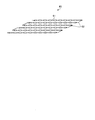
- FIG. 7 is a schematic diagram of a resistance fusion circuit according to the second embodiment.
- the resistance fusion circuit 60 includes an electrotroph 61 and an energizing member 62.
- the electrotrophic 61 is formed in a sheet shape extending in the long direction, and is formed in a three-dimensional shape by twisting the long direction in the axial direction.
- the conducting member 62 connects the ends of the electrotropes 61 so that the plurality of electrotropics 61 form a series or parallel circuit. In FIG. 7, a plurality of electrotropics 61 are connected by an energizing member 62 so as to form a series circuit.
- the sheet-shaped electrotropy 61 is cut while twisting the longitudinal direction as the axial direction, and the spiral electrotropy 61 is cut and cut. Are arranged side by side and connected by a current-carrying member 62 to form a resistance fusion circuit 60.
- the electrotropics 61 can be formed into a three-dimensional shape by twisting the electrotropics 61.
- the three-dimensionally formed electrotroph 61 is less likely to flow with respect to the melted member 11, so that the occurrence of a short circuit due to contact between circuits can be suppressed.
- the fusion strength between the members 11 to be joined can be improved.
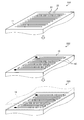
- FIG. 8 is an explanatory diagram relating to a bonding method using the resistance fusion circuit according to the third embodiment.
- the resistance welding circuit 10 is formed at the time of joining the members 11 to be joined.
- the heating wire 21 on which the protrusion 22 is formed and the energizing member 65 are prepared separately. Note that the heating wire 21 and the protrusion 22 have the same configuration as that of the first embodiment, and a description thereof will be omitted.
- a plurality of heating wires 21 are arranged on (the fusion surface 12 of) one member to be joined 11.
- the heating wire 21 is arranged such that the projecting direction of the protrusion 22 of the heating wire 21 is in the Z direction (step S21).
- the heating wires 21 are connected to each other by the conducting member 65 to form the resistance fusion circuit 10 (Step S22: circuit forming step).
- Step S23 arrangement step
- the resistance fusion circuit 10 is positioned between the members 11 to be joined (step S23: arrangement step).
- Step S23 melting step
- the member 11 to be joined is joined together with the resistance welding circuit 10.
- the members 11 to be joined can be joined to each other.
- FIG. 9 is a diagram illustrating a bonding method using the resistance fusion circuit according to the fourth embodiment.
- the resistance fusion circuit 10 is formed at the time of joining the members 11 to be joined.
- the heating wire 21 on which the protrusion 22 is formed is drawn out, and the heating wire 21 is arranged along a predetermined circuit pattern, thereby forming the resistance fusion circuit 10. Note that the heating wire 21 and the protrusion 22 have the same configuration as that of the first embodiment, and a description thereof will be omitted.
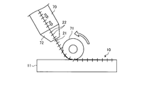
- a feeding part 70 that feeds the heating wire 21 and the heating wire 21 that is fed from the feeding part 70 are connected to one of the members 11 (the fusion surface 12).
- a pressing roller 71 pressed upward is used.
- a heater 72 is provided in the feeding part 70, and the heating wire 21 and the protruding part 22 to be fed are heated by the heater 72.
- the pressing roller 71 is in rolling contact with (the fusion surface 12 of) one of the members 11 to be joined, and the heating wire 21 and the protrusions fed from the feeding portion 70 between the pressing roller 71 and the member 11 to be joined. 22 is drawn. Then, the pressing roller 71 presses the drawn heating wire 21 and the protruding portion 22 against the member 11 to be joined. At this time, for the outer peripheral surface of the pressing roller 71, a material that does not affect the shape of the protrusion of the protrusion 22 is used.
- the feeding unit 70 forms the resistance fusion circuit 10 by arranging the heating wires 21 along a predetermined circuit pattern while feeding the heating wires 21 (circuit forming step).
- the other member 11 to be joined is arranged on the formed resistance fusion circuit 10, whereby the resistance fusion circuit 10 is positioned between the members 11 to be joined (arrangement step). Then, by energizing the resistance welding circuit 10 and melting the member 11 to be joined (melting step), the member 11 to be joined is joined together with the resistance welding circuit 10.
- the projection 22 is suitably bite into the member 11 to be joined. Can be made.
- the resistance fusion circuit 10 formed on the joined members 11 can suitably join the joined members 11 to each other.
- FIG. 10 is an explanatory diagram relating to a bonding method using the resistance fusion circuit according to the fifth embodiment.
- the joining method according to the fifth embodiment forms the resistance fusion circuit 10 at the time of joining the members 11 to be joined, as in the third and fourth embodiments.
- the heating wire 21 is arranged along a predetermined circuit pattern while the heating wire 21 is extended, and the protrusion 22 is arranged on the arranged heating wire 21. Is formed. Note that the heating wire 21 and the protrusion 22 have the same configuration as that of the first embodiment, and a description thereof will be omitted.
- a feeding part 80 that feeds out the heating wire 21, an injection part 81 that emits the projection 22, and the heating wire 21 that is fed out from the feeding part 80 are connected to one side.
- a pressing roller 82 that presses on (the fusion surface 12 of) the members to be joined 11 is used.
- the feeding section 80 feeds the heating wire 21 toward between the pressing roller 82 and the member 11 to be joined.
- the ejection unit 81 continuously ejects the protrusion 22 toward the rotating pressing roller 82. For this reason, the projections 22 emitted from the emission unit 81 are arranged at predetermined intervals along the circumferential direction on the outer peripheral surface of the pressing roller 82.
- the pressing roller 82 is provided with a heater 83, and the protrusions 22 arranged on the outer peripheral surface are heated by the heater 83.
- the pressing roller 82 is in rolling contact with (the fusion surface 12 of) one of the members 11 to be joined, and on the member 11 to be heated, the heating wire 21 that has entered between the pressing roller 82 and the member 11 to be joined.
- the heated protrusion 22 is arranged. At this time, the outer peripheral surface of the pressing roller 82 is made of a material that does not affect the shape of the protrusion of the protrusion 22.
- the drawing heating wire 21 proceeds between the pressing roller 82 and the member 11 to be joined.
- the projection 22 is ejected from the ejection section 81, the ejected projection 22 pierces the outer peripheral surface of the pressing roller 82.
- the heating wire 21 is pressed against the member 11 to be joined by the pressing roller 82, and the protrusion 22 heated by the heater 83 is arranged on the heating wire 21 by the pressing roller 82, and Dig into it.
- the feeding section 80 arranges the heating wires 21 along a predetermined circuit pattern while feeding out the heating wires 21 (heating wire arrangement step).
- the injection unit 81 and the pressing roller 82 form the resistance fusion circuit 10 by arranging the protrusion 22 on the heating wire 21 (circuit forming step).
- the other member 11 to be joined is arranged on the formed resistance fusion circuit 10, whereby the resistance fusion circuit 10 is positioned between the members 11 to be joined (arrangement step).
- the resistance fusion circuit 10 is positioned between the members 11 to be joined (arrangement step).
- the resistance welding circuit 10 melting the member 11 to be joined
- the member 11 to be joined is joined together with the resistance welding circuit 10.
- the resistance fusion circuit 10 As described above, according to the fifth embodiment, by forming the resistance fusion circuit 10 on the member 11 to be joined while heating the protrusion 22, the protrusion 22 is suitably bite into the member 11 to be joined. Can be. For this reason, the resistance fusion circuit 10 formed on the joined members 11 can suitably join the joined members 11 to each other.
- FIG. 11 is an explanatory diagram relating to a joining method using a resistance fusion circuit according to the sixth embodiment.
- the resistance fusion circuit 10 is formed at the time of joining the members 11 to be joined, as in the third to fifth embodiments.
- the heating wire 21 is arranged along a predetermined circuit pattern while the heating wire 21 is being fed out, and the protrusion 22 is arranged on the arranged heating wire 21, whereby the resistance fusion circuit 10 Is formed.
- the heating wire 21 and the protrusion 22 have the same configuration as that of the first embodiment, and a description thereof will be omitted.
- a feeding part 90 that feeds out the heating wire 21, an injection part 91 that emits the protrusion 22, and the heating wire 21 that is drawn out from the feeding part 90 are connected to one of the A pressing roller 92 that presses on (the fusion surface 12 of) the members to be joined 11 is used.
- the feeding section 90 feeds the heating wire 21 toward between the pressing roller 92 and the member 11 to be joined.
- the injection unit 91 emits the protrusion 22 toward the heating wire 21 arranged on the member 11 to be joined.
- the emitting section 91 is provided with a heater 93, and the projected projection 22 is heated by the heater 93. Therefore, the heated protruding portion 22 emitted from the emitting portion 91 is arranged on the heating wire 21 and stabbed into the member 11 to be joined.
- the pressing roller 92 is in rolling contact with (the fused surface 12 of) the one member 11 to be joined, and presses the heating wire 21 between the pressing roller 82 and the member 11 to be joined onto the member 11 to be joined. ing.
- the drawn heating wire 21 proceeds between the pressing roller 92 and the member 11 to be bonded. Then, the heating wire 21 is arranged on the member to be joined 11 by being pressed against the member to be joined 11 by the pressing roller 92. Then, the feeding unit 90 arranges the heating wires 21 along a predetermined circuit pattern while feeding out the heating wires 21 (heating wire arrangement step). Subsequently, when the protruding portion 22 is emitted from the emitting portion 91 to the heating wire on the member 11 to be joined, the ejected protruding portion 22 is arranged on the heating wire 21 and the member 11 To form the resistance fusion circuit 10 (circuit forming step).
- the other member 11 to be joined is arranged on the formed resistance fusion circuit 10, whereby the resistance fusion circuit 10 is positioned between the members 11 to be joined (arrangement step). Then, by energizing the resistance welding circuit 10 and melting the member 11 to be joined (melting step), the member 11 to be joined is joined together with the resistance welding circuit 10.
- the resistance fusion circuit 10 formed on the joined members 11 can suitably join the joined members 11 to each other.
- FIG. 12 is an explanatory diagram relating to a joining method using a resistance fusion circuit according to the seventh embodiment.
- the resistance fusion circuit 10 is formed at the time of joining the members 11 to be joined.
- a heating wire 101 serving as a predetermined circuit pattern is drawn using a conductive paint (conductive material), and a protrusion 102 is formed on the drawn heating wire 101 using a conductive paint.
- a conductive paint conductive material
- a protrusion 102 is formed on the drawn heating wire 101 using a conductive paint.
- the heating wire 101 is formed using, for example, a plating spray 105 that sprays a conductive paint, and a predetermined circuit pattern is formed on the member 11 to be joined with a predetermined thickness by the conductive paint sprayed from the plating spray 105. Is formed by being drawn.
- the protruding portion 102 is formed by using a plating spray 106 for spraying a conductive paint, and is formed on the heating wire 101 of the member 11 to be joined by the conductive paint sprayed from the plating spray 106. It is formed by being drawn on top of. For this reason, in the conductive paint, a first portion having a smaller thickness in the Z direction (opposing direction) and a second portion having a larger thickness than the first portion are formed. Is formed as
- a conductive paint is sprayed on the member 11 to be joined by using the plating spray 105 to form the heating wire 101 serving as the thickness of the first portion and the circuit pattern.
- a conductive paint is sprayed on the heating wire 101 formed on the member 11 to be joined by using the plating spray 106, and the second portion thicker than the heating wire 101 is formed as the protrusion 102.
- the resistance fusion circuit 100 is formed (circuit formation step).
- the resistance fusion circuit 100 is positioned between the members 11 to be joined (arrangement step).
- the resistance fusion circuit 100 is positioned between the members 11 to be joined (arrangement step).
- the member 11 to be joined is joined together with the resistance fusion circuit 100.
- a plurality of protrusions 102 can be formed by increasing the thickness of the conductive material. Also, by forming a plurality of protrusions 102 on the heating wire 101 by attaching a conductive material, the resistance fusion circuit 100 formed on the members to be joined 11 suitably joins the members to be joined 11 to each other. be able to.
- the heating wire 101 and the projection 102 are formed using two plating sprays 105 and 106, respectively.
- the heating wire 101 and the projection 102 may be formed using one spray.
- the plurality of protrusions 102 were formed by forming the first portion and the second portion while changing the thickness of the conductive paint adhered on the member 11 to be joined using one spray.
- the heating wire 101 may be formed.
- Resistance fusion circuit 11 Member to be joined 12 Fusion surface 14 Carbon fiber 15 Thermoplastic resin 21 Heating wire 22 Projection part 23 Protective film 40 Modeling device 41 Modeling table 42 Inkjet head 43 Guide bar 45 Base material 46 Resist 48 Base material 51 Punch roller 52 Guide roller 53, 54 Transport roller 60 Resistance fusing circuit (Embodiment 2) 61 Electrotrophic 65 Conducting member 70 Feeding part 71 Pressing roller 72 Heater 80 Feeding part 81 Injection part 82 Pressing roller 83 Heater 90 Feeding part 91 Injection part 92 Pressing roller 93 Heater 100 Resistance fusion circuit 101 Heating wire 102 Projection 105 Plating spray 106 Plating spray
Landscapes
- Engineering & Computer Science (AREA)
- Mechanical Engineering (AREA)
- Manufacturing & Machinery (AREA)
- Chemical & Material Sciences (AREA)
- Materials Engineering (AREA)
- Composite Materials (AREA)
- Lining Or Joining Of Plastics Or The Like (AREA)
- Surface Heating Bodies (AREA)
- Resistance Heating (AREA)
Abstract
被接合部材(11)同士の間に配置される抵抗融着回路(10)において、電熱線(21)と、被接合部材(11)同士が対向する対向方向に沿って電熱線(21)から突出する複数の突起部(22)とを備える。突起部(22)の突出方向における長さは、被接合部材(11)が溶融する融着層の層厚に対して、層厚の半分以上の長さとなっている。電熱線(21)及び突起部(22)を被覆する保護フィルムを、さらに備え、保護フィルムを被接合部材(11)と同じ材料としてもよい。また、突起部(22)は、電熱線(21)に比して、熱伝導性が高い材料としてもよい。
Description
本発明は、接合用発熱回路、接合体、接合用発熱回路の製造方法及び接合方法に関するものである。
従来、接合用発熱回路として、一対の接合部材の間に配置される抵抗発熱体が知られている(例えば、特許文献1参照)。接合部材は、繊維強化熱可塑性樹脂部材であり、抵抗発熱体は、一対の接合部材の間において通電させられることにより、一対の接合部材を融着させている。
ところで、抵抗発熱体等の接合用発熱回路は、融着部を均一に昇温させる必要があることから、密に配置する必要がある。しかしながら、接合用発熱回路を密に配置すると、樹脂が融けた後、接合用発熱回路は、硬化前の融けた樹脂内に留まることができずに動いてしまい、隣の接合用発熱回路と接触することで、ショートしてしまう可能性がある。また、融着完了後、接合用発熱回路は、融着面に残置することから、融着強度が低下する可能性がある。
そこで、本発明は、部材間の接合を好適に行うことができる接合用発熱回路、接合体、接合用発熱回路の製造方法及び接合方法を提供することを課題とする。
本発明の接合用発熱回路は、部材同士の間に配置される接合用発熱回路において、電熱線と、前記部材同士が対向する対向方向に沿って前記電熱線から突出する複数の突起部と、を備えることを特徴とする。
この構成によれば、硬化前の流動性を有する部材に対して、突起部が抵抗となり、接合用発熱回路が流動し難くなるため、回路同士の接触によるショートの発生を抑制することができる。また、突起部が硬化前の部材に食い込むため、部材同士の接合強度の向上を図ることができる。なお、対向方向に沿う突起部の突出方向は、例えば、部材が溶融する融着面に対して垂直となる方向であるが、必ずしも垂直である必要はなく、融着面に対して垂直となる方向の成分を含む方向であればよい。また、複数の突起部の突出方向における長さは、同じ長さであってもよいし、異なる長さであってもよい。
また、前記突起部の突出方向における長さは、前記部材が溶融する融着層の層厚に対して、前記層厚の半分以上の長さとなっていることが、好ましい。
この構成によれば、部材が溶融する場合、突起部を融着層に対して適切に食い込ませることができるため、抵抗融着回路の流動を適切に抑制し、また、部材同士を適切に融着させることができる。
また、前記突起部は、前記電熱線に比して、熱伝導性が高い材料となっていることが、好ましい。
この構成によれば、突起部と接する部材を好適に溶融させることができる。
また、隣接する前記突起部同士の間隔は、前記突起部の突出方向における長さよりも長いことが、好ましい。
この構成によれば、突起部が傾倒しても、隣接する突起部に接触することを抑制することができるため、突起部同士の接触によるショートの発生を抑制することができる。
また、前記電熱線及び前記突起部を被覆するフィルムを、さらに備え、前記フィルムは、前記部材と同じ材料となっていることが、好ましい。
この構成によれば、電熱線及び突起部がフィルムに保護された状態で、部材同士の間に配置することができる。また、フィルムが部材と同じ材料であることから、接合する部材とフィルムとを好適に一体化することができる。なお、フィルムは、例えば、熱可塑性樹脂が適用される。
本発明の他の接合用発熱回路は、部材同士の間に配置される接合用発熱回路において、長尺方向に延在するシート状の電熱帯を備え、前記電熱帯は、前記長尺方向を軸方向として捻って形成されることを特徴とする。
この構成によれば、電熱帯を捻ることにより、電熱帯を3次元形状とすることができる。3次元形状となる電熱帯は、硬化前の流動性を有する部材に対して流動し難くなるため、回路同士の接触によるショートの発生を抑制することができる。また、3次元形状となる電熱帯は、溶融した部材に食い込むため、部材同士の接合強度の向上を図ることができる。
本発明の接合体は、上記の接合用発熱回路と、前記接合用発熱回路を挟んで両側に設けられる部材と、を備えることを特徴とする。
この構成によれば、一対の部材を接合用発熱回路を用いて接合することで、部材間が好適に接合された接合体とすることができる。
本発明の接合用発熱回路の製造方法は、部材同士の間に配置される接合用発熱回路を製造する接合用発熱回路の製造方法において、前記接合用発熱回路は、電熱線と、前記部材同士が対向する対向方向に沿って前記電熱線から突出する複数の突起部と、を有し、導電性インクを吐出ヘッドから造形台へ向かって吐出して、造形台上に、前記電熱線と複数の前記突起部とを造形する造形工程を備えることを特徴とする。
この構成によれば、吐出ヘッドから吐出した導電性インクにより、電熱線と複数の突起部とを造形することで、接合用発熱回路を容易に形成することができる。
本発明の他の接合用発熱回路の製造方法は、基材を用いて、部材同士の間に配置される接合用発熱回路を製造する接合用発熱回路の製造方法において、前記接合用発熱回路は、電熱線と、前記部材同士が対向する対向方向に沿って前記電熱線から突出する複数の突起部と、を有し、前記基材上の複数の前記突起部を形成する位置に、レジストを塗布するレジスト塗布工程と、前記レジストを塗布した前記基材をエッチングするエッチング工程と、エッチング後の前記基材に塗布された前記レジストを除去して、前記接合用発熱回路を形成するレジスト除去工程と、を備えることを特徴とする。
この構成によれば、電熱線と複数の突起部との形状を精度良く形成することができる。
本発明の他の接合用発熱回路の製造方法は、基材を用いて、部材同士の間に配置される接合用発熱回路を製造する接合用発熱回路の製造方法において、前記接合用発熱回路は、電熱線と、前記部材同士が対向する対向方向に沿って前記電熱線から突出する複数の突起部と、を有し、前記基材を挟持するパンチローラにより、前記基材に、前記電熱線を切り出すための切込み部と、前記突起部を形成する位置における切込みを非形成とした非切込み部と、を形成し、前記基材から前記電熱線を離形するときに、前記非切込み部を引き裂くことで、前記突起部が対向方向となるように前記電熱線から前記突起部を突出させる打ち抜き工程を備えることを特徴とする。
この構成によれば、基材から電熱線を離形することで、複数の突起部を対向方向に突出させることができるため、接合用発熱回路を容易に形成することができる。
本発明の接合方法は、部材同士の間に、接合用発熱回路を配置して、前記部材同士を接合する接合方法において、前記部材同士が対向する対向方向に沿って突出する複数の突起部が形成された電熱線を、前記部材上に複数配置し、前記電熱線同士を通電部材により接続して、前記接合用発熱回路を形成する回路形成工程と、形成された前記接合用発熱回路上に前記部材を配置することで、前記接合用発熱回路を前記部材同士の間に位置させる配置工程と、前記接合用発熱回路に通電を行って、前記部材を接合する接合工程と、を備えることを特徴とする。
この構成によれば、部材上に、接合用発熱回路を形成した後、部材同士を接合することができる。なお、接合用発熱回路は、複数の電熱線が直列または並列の回路となるように、通電部材により接続される。
また、本発明の他の接合方法は、部材同士の間に、接合用発熱回路を配置して、前記部材同士を接合する接合方法において、前記部材同士が対向する対向方向に沿って突出する複数の突起部が形成された電熱線を加熱しながら、前記電熱線が所定の回路パターンとなるように、前記電熱線を前記部材上に配置して、前記接合用発熱回路を形成する回路形成工程と、形成された前記接合用発熱回路上に前記部材を配置することで、前記接合用発熱回路を前記部材同士の間に位置させる配置工程と、前記接合用発熱回路に通電を行って、前記部材を接合する接合工程と、を備えることを特徴とする。
この構成によれば、電熱線及び突起部を加熱しながら部材上に電熱線を配置することで、突起部を部材に好適に食い込ませることができる。このため、部材上に形成された接合用発熱回路は、部材同士を好適に接合することができる。
また、本発明の他の接合方法は、部材同士の間に、接合用発熱回路を配置して、前記部材同士を接合する接合方法において、電熱線が所定の回路パターンとなるように、前記電熱線を前記部材上に配置する電熱線配置工程と、前記部材同士が対向する対向方向に沿って前記電熱線から突出させる複数の突起部を加熱しながら、複数の前記突起部を前記電熱線に配置して、前記接合用発熱回路を形成する回路形成工程と、形成された前記接合用発熱回路上に前記部材を配置することで、前記接合用発熱回路を前記部材同士の間に位置させる配置工程と、前記接合用発熱回路に通電を行って、前記部材を接合する接合工程と、を備えることを特徴とする。
この構成によれば、突起部を加熱しながら部材上に接合用発熱回路を形成することで、突起部を部材に好適に食い込ませることができる。このため、部材上に形成された接合用発熱回路は、部材同士を好適に接合することができる。
また、本発明の他の接合方法は、部材同士の間に、接合用発熱回路を配置して、前記部材同士を接合する接合方法において、前記部材上に導電性材料を付着させて、前記部材同士が対向する対向方向に沿って突出する複数の突起部が形成された電熱線を、前記部材上に配置して、前記接合用発熱回路を形成する回路形成工程と、形成された前記接合用発熱回路上に前記部材を配置することで、前記接合用発熱回路を前記部材同士の間に位置させる配置工程と、前記接合用発熱回路に通電を行って、前記部材を接合する接合工程と、を備え、前記回路形成工程では、前記導電性材料の前記対向方向における厚さが薄い第1部位と、前記第1部位に比して厚さが厚い第2部位とを形成し、前記第2部位を前記突起部として形成することを特徴とする。
この構成によれば、導電性材料の厚さを厚くすることで、複数の突起部を形成することができる。また、導電性材料を付着させて電熱線に複数の突起部を形成することで、部材上に形成された接合用発熱回路は、部材同士を好適に接合することができる。
以下に、本発明に係る実施形態を図面に基づいて詳細に説明する。なお、この実施形態によりこの発明が限定されるものではない。また、下記実施形態における構成要素には、当業者が置換可能かつ容易なもの、あるいは実質的に同一のものが含まれる。さらに、以下に記載した構成要素は適宜組み合わせることが可能であり、また、実施形態が複数ある場合には、各実施形態を組み合わせることも可能である。
[実施形態1]
実施形態1に係る接合用発熱回路は、被接合部材11同士を融着するために用いられる発熱体であり、いわゆる抵抗融着回路10である。先ず、図1を参照して、抵抗融着回路10を用いて形成される接合体1について説明する。
実施形態1に係る接合用発熱回路は、被接合部材11同士を融着するために用いられる発熱体であり、いわゆる抵抗融着回路10である。先ず、図1を参照して、抵抗融着回路10を用いて形成される接合体1について説明する。
図1は、実施形態1に係る接合体を模式的に表した断面図である。図1に示すように、接合体1は、抵抗融着回路10と、抵抗融着回路10を挟んで両側に設けられる2つの被接合部材11とを含んで構成されている。ここで、抵抗融着回路10及び被接合部材11の厚さ方向をZ方向とし、厚さ方向に直交する所定の方向をX方向とし、Z方向及びX方向に直交する方向をY方向とする。
抵抗融着回路10は、被接合部材11の融着面12に沿って広がる薄膜の回路となっている。被接合部材11は、例えば、炭素繊維14に熱可塑性樹脂15を含浸させた複合材、いわゆる、CFRTP(Carbon Fiber Reinforced Thermoplastics)である。なお、実施形態1では、CFRTPに適用して説明するが、加熱されることにより溶融する樹脂を含む部材であれば、いずれの部材であってもよく、特に限定されない。また、実施形態1では、加熱されることにより溶融する樹脂を含む被接合部材11に適用して説明するが、熱硬化性の樹脂を含む被接合部材に適用してもよく、被接合部材として、例えば、炭素繊維等の強化繊維に熱硬化性樹脂を含浸させた複合材に適用してもよい。この場合、接合用発熱回路は、被接合部材同士を熱硬化させるために用いられる発熱回路となっている。つまり、接合用発熱回路は、半硬化状態となる被接合部材(複合材)を加熱して熱硬化させることで、被接合部材11同士を接合してもよい。なお、熱硬化性の樹脂を含む被接合部材としては、上記の複合材の他、部材同士の間に配置される熱硬化性樹脂からなる接着剤シートであってもよい。
このような接合体1を形成する場合、先ず、2つの被接合部材11の融着面12の間に、抵抗融着回路10を配置することで、被接合部材11と抵抗融着回路10とをZ方向に重ね合わせる。この後、抵抗融着回路10に通電を行うことで、抵抗融着回路10を発熱させる。抵抗融着回路10が発熱すると、被接合部材11の融着面12が溶融することで、被接合部材11が抵抗融着回路10と共に一体となる。そして、冷却することにより、被接合部材11同士が接合して、接合体1が形成される。
次に、図2を参照して、抵抗融着回路10について説明する。図2は、実施形態1に係る抵抗融着回路の模式図である。抵抗融着回路10は、電熱線21と、電熱線から突出する複数の突起部22と、を備える。
電熱線21は、通電することにより発熱する金属線であり、XY面内において所定の配線パターンとなっている。図2において、電熱線21は、例えば、Y方向に往復しながら、X方向に向かって蛇行する配線パターンとなっており、XY面内において、略方形状に形成されている。なお、配線パターンは特に限定されない。また、電熱線21は、その線径が、被接合部材11の溶融条件等に応じて適切となる径となっており、同様に、隣接する電熱線21同士の間隔は、被接合部材11の溶融条件等に応じて適切となる間隔となっている。
複数の突起部22は、被接合部材11同士が対向する対向方向に沿って、すなわち、Z方向に沿って、電熱線21から突出して形成されている。なお、Z方向に沿う突起部22の突出方向は、例えば、被接合部材11が溶融する融着面12に対して垂直となる方向であるが、必ずしも垂直である必要はなく、融着面12に対して垂直となる方向の成分を含む方向であればよい。また、突起部22は、その形状が突出方向の先端へ向かって先細りする楔形状であってもよいし、突出方向の先端へ向かって広がる抜け止めが形成された逆三角形状であってもよく、特に限定されない。
突起部22の突出方向における長さは、被接合部材11が溶融する融着層の層厚に対して、層厚の半分以上の長さとなっている。ここで、融着層とは、抵抗融着回路10によって被接合部材11が溶融するZ方向の厚みを有する層であり、例えば、融着面12から炭素繊維に至るまでの層である。また、突起部22の突出方向における長さは、電熱線21上において隣接する突起部22同士の間隔に比して短いものとなっている。換言すれば、電熱線21上において隣接する突起部22同士の間隔は、突起部22の突出方向における長さよりも長くなっている。また、複数の突起部22の突出方向における長さは、同じ長さであってもよいし、異なる長さであってもよい。
また、突起部22は、電熱線21と同じ材料を用いて構成してもよいし、異なる材料を用いて構成してもよい。異なる材料を用いる場合、突起部22は、電熱線21に比して、熱伝導性が高い材料を用いている。このため、抵抗融着回路10への通電時において、電熱線21の発熱を突起部22へ効率よく伝熱することが可能となる。
また、抵抗融着回路10は、電熱線21及び突起部22を被覆する保護フィルム23(図3参照)を、さらに備えてもよい。この場合、保護フィルム23は、被接合部材11に含まれる樹脂と同じ材料とすることで、抵抗融着回路10への通電時において、保護フィルム23を付けたまま、使用することが可能となる。なお、保護フィルム23は、被接合部材11に含まれる樹脂と異なる材料であってもよい。この場合、抵抗融着回路10への通電時において、保護フィルム23を付けたまま、使用してもよいし、保護フィルム23を引き剥がしてもよい。例えば、被接合部材11に含まれる樹脂が熱可塑性樹脂であって、つまり、被接合部材11が熱可塑複合材であって、保護フィルム23として熱硬化性樹脂からなるフィルム状の接着剤を用いる場合、保護フィルム23を付けたまま使用することで、被接合部材11と保護フィルム23とを一体としてもよい。
次に、図3から図6を参照して、抵抗融着回路10の製造方法に関する処理の一例について説明する。図3から図5は、実施形態1に係る抵抗融着回路の製造方法に関する一例の説明図である。図6は、実施形態1に係る抵抗融着回路の製造方法により形成される抵抗融着回路を模式的に表した平面図である。
図3では、インクジェットヘッド42から導電性インクを吐出して3次元造形を行うことが可能な造形装置40を用いて、抵抗融着回路10を形成している。造形装置40は、造形台41と、インクジェットヘッド42と、インクジェットヘッド42の走査方向における移動を案内するガイドバー43と、を備えている。
造形台41は、インクジェットヘッド42と対向する上面が平坦面となっており、インクジェットヘッド42から吐出されたインク液滴が付着する。抵抗融着回路10は、造形台41上に造形される。
インクジェットヘッド42は、ガイドバー43により走査方向に案内されながら、導電性インク及び熱可塑性樹脂を含む樹脂用インクを吐出する。インクジェットヘッド42は、導電性インク及び樹脂用インクを吐出して、単位層を造形すると共に、単位層をZ方向に積層して、抵抗融着回路10を形成する。
図3において、抵抗融着回路10は、上記の造形装置40を用いて造形される。ここで、図3では、一例として、保護フィルム23付きの抵抗融着回路10を造形する場合について説明する。具体的に、造形装置40は、保護フィルム23付きの抵抗融着回路10をZ方向において単位層ごとに分割したデータである単位層データを用いている。造形装置40は、この単位層データに基づいて、造形台41上に、インクジェットヘッド42から導電性インク及び樹脂用インクを吐出して、単位層を下層から順に複数積層することで、電熱線21、複数の突起部22及び保護フィルム23からなる抵抗融着回路10を造形する造形工程を実行する。なお、図3に示す造形工程では、電熱線21と複数の突起部22とを、導電性インクを用いて造形したが、造形台41上に予め用意された電熱線21を配置し、この電熱線21上に導電性インクを吐出して、複数の突起部22を形成してもよい。このとき、形成される複数の突起部22は、電熱線21の物理特性とは異なる物質としてもよい。具体的に、突起部22の物理特性としては、電熱線21に比して熱伝導率が高いもの、電熱線21に比して硬度が高いもの、電熱線21に比して電気伝導率が高いもの等がある。
次に、図4では、エッチングを行って、抵抗融着回路10を形成している。ここで、図4では、一例として、保護フィルム23を省いた抵抗融着回路10を形成する場合について説明する。先ず、抵抗融着回路10となる前の状態である基材45に対して、複数の突起部22が形成される位置に、レジスト46を塗布する(ステップS11:レジスト塗布工程)。この後、レジスト46を塗布した基材45に対してエッチング処理を行う(ステップS12:エッチング工程)。エッチング工程では、エッチング液を用いたウェットエッチングを行ってもよいし、エッチング用ガスを用いたドライエッチングを行ってもよく、特に限定されない。そして、エッチング後の基材45に塗布されたレジスト46を除去することで(ステップS13:レジスト除去工程)、抵抗融着回路10を形成する。
次に、図5及び図6では、一対のパンチローラ51を用いて、抵抗融着回路10を形成している。一対のパンチローラ51は、抵抗融着回路10となる前の状態である基材48に対して、抵抗融着回路10を形成するための溝をパンチングする打ち抜き工程を実行する。一対のパンチローラ51により溝がパンチングされた基材48は、一例として、図6に示すものとなり、抵抗融着回路10を構成する部位と、抵抗融着回路10を挟んで両側に設けられ、抵抗融着回路10から引き剥がされる一対の部位48a,48bとに分けられる。このとき、基材48には、電熱線21を切り出すための切込み部が形成される一方で、突起部22を形成する位置において切込み部が形成されない(非切込み部)ものとなっている。
一対のパンチローラ51によりパンチングされた基材48は、搬送方向の下流側に設けられる一対のガイドローラ52により、部位48aが、基材48の表面側(図6の上側)に向かって案内され、部位48bが、基材48の裏面側(図6の下側)に向かって案内される。ガイドローラ52を通過した部位48aは、搬送方向の下流側に設けられる搬送ローラ53によって搬送されることで、基材48から引き剥がされる。同様に、ガイドローラ52を通過した部位48bは、搬送方向の下流側に設けられる搬送ローラ54によって搬送されることで、基材48から引き剥がされる。そして、基材48から一対の部位48a,48bが引き剥がされることで、抵抗融着回路10が形成される。このとき、基材48から電熱線21を離形するときに、非切込み部を引き裂くことで、突起部22を突出させる。
以上のように、実施形態1によれば、被接合部材11の接合時において、溶融した被接合部材11に対して、突起部22が抵抗となり、抵抗融着回路10が流動し難くなるため、回路同士の接触によるショートの発生を抑制することができる。また、突起部22が溶融した被接合部材11に食い込むため、被接合部材11同士の融着強度(接合強度)の向上を図ることができる。
また、実施形態1によれば、突起部22の長さを、融着層の層厚の半分以上の長さとすることで、突起部22を融着層に対して適切に食い込ませることができるため、抵抗融着回路10の流動を適切に抑制し、また、被接合部材11同士を適切に融着させることができる。
また、実施形態1によれば、突起部22を電熱線21に比して熱伝導性の高い材料とすることで、突起部22と接する被接合部材11を好適に溶融させることができる。
また、実施形態1によれば、隣接する突起部22同士の間隔を、突起部22の突出方向における長さよりも長くすることで、突起部22が傾倒しても、隣接する突起部22に接触することを抑制することができるため、突起部22同士の接触によるショートの発生を抑制することができる。
また、実施形態1によれば、保護フィルム23により、電熱線21及び突起部22を保護した状態で取り扱うことができるため、突起部22への損傷を軽減することができる。
また、実施形態1によれば、インクジェットヘッド42から吐出した導電性インクにより、電熱線21と複数の突起部22とを造形することで、抵抗融着回路10を容易に形成することができる。
また、実施形態1によれば、エッチングにより抵抗融着回路10を形成することで、電熱線21と複数の突起部22との形状を精度良く形成することができる。
また、実施形態1によれば、パンチローラ51により基材48に溝(切込み部)を形成して、基材48から電熱線21を離形することで、複数の突起部22を突出させることができるため、抵抗融着回路10を容易に形成することができる。
[実施形態2]
次に、図7を参照して、実施形態2に係る抵抗融着回路60について説明する。なお、実施形態2では、重複した記載を避けるべく、実施形態1と異なる部分について説明し、実施形態1と同様の構成である部分については、同じ符号を付して説明する。図7は、実施形態2に係る抵抗融着回路の模式図である。
次に、図7を参照して、実施形態2に係る抵抗融着回路60について説明する。なお、実施形態2では、重複した記載を避けるべく、実施形態1と異なる部分について説明し、実施形態1と同様の構成である部分については、同じ符号を付して説明する。図7は、実施形態2に係る抵抗融着回路の模式図である。
実施形態2の抵抗融着回路60は、電熱帯61と、通電部材62とを備えている。電熱帯61は、長尺方向に延在するシート状に形成され、長尺方向を軸方向として捻ることで、3次元形状に形成されている。通電部材62は、電熱帯61の端部同士を接続して、複数の電熱帯61が、直列または並列の回路となるようにしている。なお、図7では、複数の電熱帯61が直列の回路となるように、通電部材62により接続されている。
図7に示す抵抗融着回路60を製造する場合、一例として、シート状の電熱帯61を、長尺方向を軸方向として捻りながら、電熱帯61を裁断し、裁断したらせん状の電熱帯61を複数並べて、通電部材62により接続することで、抵抗融着回路60とする。
以上のように、実施形態2によれば、電熱帯61を捻ることにより、電熱帯61を3次元形状とすることができる。3次元形状となる電熱帯61は、溶融した被接合部材11に対して流動し難くなるため、回路同士の接触によるショートの発生を抑制することができる。また、3次元形状となる電熱帯61は、溶融した被接合部材11に食い込むため、被接合部材11同士の融着強度の向上を図ることができる。
[実施形態3]
次に、図8を参照して、実施形態3に係る抵抗融着回路を用いた接合方法について説明する。なお、実施形態3では、重複した記載を避けるべく、実施形態1及び2と異なる部分について説明し、実施形態1及び2と同様の構成である部分については、同じ符号を付して説明する。図8は、実施形態3に係る抵抗融着回路を用いた接合方法に関する説明図である。
次に、図8を参照して、実施形態3に係る抵抗融着回路を用いた接合方法について説明する。なお、実施形態3では、重複した記載を避けるべく、実施形態1及び2と異なる部分について説明し、実施形態1及び2と同様の構成である部分については、同じ符号を付して説明する。図8は、実施形態3に係る抵抗融着回路を用いた接合方法に関する説明図である。
実施形態3に係る接合方法は、被接合部材11の接合時において、抵抗融着回路10を形成している。なお、実施形態3の接合方法に用いられる抵抗融着回路10は、突起部22が形成された電熱線21と、通電部材65とが別体の状態で用意されている。なお、電熱線21及び突起部22は、実施形態1と同様の構成となっているため、説明を省略する。
図8に示すように、先ず、一方の被接合部材11(の融着面12)上に、電熱線21を複数配置する。このとき、電熱線21の突起部22の突出方向が、Z方向となるように、電熱線21を配置する(ステップS21)。この後、電熱線21同士を通電部材65により接続して、抵抗融着回路10を形成する(ステップS22:回路形成工程)。次に、形成された抵抗融着回路10上に、他方の被接合部材11を配置することで、抵抗融着回路10を被接合部材11同士の間に位置させる(ステップS23:配置工程)。そして、抵抗融着回路10に通電を行って、被接合部材11を溶融させる(ステップS23:溶融工程)ことで、抵抗融着回路10と共に被接合部材11を接合する。
以上のように、実施形態3によれば、被接合部材11上に、抵抗融着回路10を形成した後、被接合部材11同士を接合することができる。
[実施形態4]
次に、図9を参照して、実施形態4に係る抵抗融着回路を用いた接合方法について説明する。なお、実施形態4でも、重複した記載を避けるべく、実施形態1から3と異なる部分について説明し、実施形態1から3と同様の構成である部分については、同じ符号を付して説明する。図9は、実施形態4に係る抵抗融着回路を用いた接合方法に関する説明図である。
次に、図9を参照して、実施形態4に係る抵抗融着回路を用いた接合方法について説明する。なお、実施形態4でも、重複した記載を避けるべく、実施形態1から3と異なる部分について説明し、実施形態1から3と同様の構成である部分については、同じ符号を付して説明する。図9は、実施形態4に係る抵抗融着回路を用いた接合方法に関する説明図である。
実施形態4に係る接合方法は、実施形態3と同様に、被接合部材11の接合時において、抵抗融着回路10を形成している。実施形態4の接合方法では、突起部22が形成された電熱線21を繰り出しながら、所定の回路パターンに沿って電熱線21を配置することで、抵抗融着回路10を形成している。なお、電熱線21及び突起部22は、実施形態1と同様の構成となっているため、説明を省略する。
図9に示すように、実施形態4の接合方法では、電熱線21を繰り出す繰出し部70と、繰出し部70から繰り出された電熱線21を、一方の被接合部材11(の融着面12)上に押し付ける押付ローラ71とが用いられる。
繰出し部70には、ヒータ72が設けられており、繰り出される電熱線21及び突起部22をヒータ72により加熱している。押付ローラ71は、一方の被接合部材11(の融着面12)に転接しており、押付ローラ71と被接合部材11との間に、繰出し部70から繰り出された電熱線21及び突起部22を引き込んでいる。そして、押付ローラ71は、引き込んだ電熱線21及び突起部22を被接合部材11に押圧する。このとき、押付ローラ71の外周面は、突起部22の突起形状に影響を与えないような材料が用いられる。
実施形態4の接合方法において、上記の繰出し部70から、突起部22が形成された電熱線21が加熱されて繰り出されると、繰り出された電熱線21は、押付ローラ71と被接合部材11との間へ向かって進む。そして、加熱された電熱線21及び突起部22は、押付ローラ71により被接合部材11に押し付けられることで、突起部22が被接合部材11に食い込む。そして、繰出し部70は、電熱線21を繰り出しながら、所定の回路パターンに沿って電熱線21を配置することで、抵抗融着回路10を形成する(回路形成工程)。次に、形成された抵抗融着回路10上に、他方の被接合部材11を配置することで、抵抗融着回路10を被接合部材11同士の間に位置させる(配置工程)。そして、抵抗融着回路10に通電を行って、被接合部材11を溶融させる(溶融工程)ことで、抵抗融着回路10と共に被接合部材11を接合する。
以上のように、実施形態4によれば、電熱線21及び突起部22を加熱しながら被接合部材11上に電熱線21を配置することで、突起部22を被接合部材11に好適に食い込ませることができる。このため、被接合部材11上に形成された抵抗融着回路10は、被接合部材11同士を好適に接合することができる。
[実施形態5]
次に、図10を参照して、実施形態5に係る抵抗融着回路を用いた接合方法について説明する。なお、実施形態5でも、重複した記載を避けるべく、実施形態1から4と異なる部分について説明し、実施形態1から4と同様の構成である部分については、同じ符号を付して説明する。図10は、実施形態5に係る抵抗融着回路を用いた接合方法に関する説明図である。
次に、図10を参照して、実施形態5に係る抵抗融着回路を用いた接合方法について説明する。なお、実施形態5でも、重複した記載を避けるべく、実施形態1から4と異なる部分について説明し、実施形態1から4と同様の構成である部分については、同じ符号を付して説明する。図10は、実施形態5に係る抵抗融着回路を用いた接合方法に関する説明図である。
実施形態5に係る接合方法は、実施形態3及び4と同様に、被接合部材11の接合時において、抵抗融着回路10を形成している。実施形態5の接合方法では、電熱線21を繰り出しながら、所定の回路パターンに沿って電熱線21を配置し、配置した電熱線21上に突起部22を配置することで、抵抗融着回路10を形成している。なお、電熱線21及び突起部22は、実施形態1と同様の構成となっているため、説明を省略する。
図10に示すように、実施形態5の接合方法では、電熱線21を繰り出す繰出し部80と、突起部22を射出する射出部81と、繰出し部80から繰り出された電熱線21を、一方の被接合部材11(の融着面12)上に押し付ける押付ローラ82とが用いられる。
繰出し部80は、押付ローラ82と被接合部材11との間へ向けて、電熱線21を繰り出している。射出部81は、突起部22を、回転する押付ローラ82へ向けて連続的に射出している。このため、射出部81から射出された突起部22は、押付ローラ82の外周面において、周方向に沿って所定の間隔を空けて並べられる。押付ローラ82には、ヒータ83が設けられており、外周面に並んだ突起部22をヒータ83により加熱している。押付ローラ82は、一方の被接合部材11(の融着面12)に転接しており、被接合部材11上において、押付ローラ82と被接合部材11との間に入り込んだ電熱線21に、加熱した突起部22を配置している。このとき、押付ローラ82の外周面は、突起部22の突起形状に影響を与えないような材料が用いられる。
実施形態5の接合方法において、上記の繰出し部80から、電熱線21が繰り出されると、繰り出された電熱線21は、押付ローラ82と被接合部材11との間へ向かって進む。一方で、射出部81から突起部22が射出されると、射出された突起部22は、押付ローラ82の外周面に突き刺さる。そして、電熱線21は、押付ローラ82により被接合部材11に押し付けられると共に、ヒータ83により加熱された突起部22は、押付ローラ82により電熱線21上に配置されると共に、被接合部材11に食い込む。そして、繰出し部80は、電熱線21を繰り出しながら、所定の回路パターンに沿って電熱線21を配置する(電熱線配置工程)。また、射出部81及び押付ローラ82は、電熱線21に突起部22を配置することで、抵抗融着回路10を形成する(回路形成工程)。次に、形成された抵抗融着回路10上に、他方の被接合部材11を配置することで、抵抗融着回路10を被接合部材11同士の間に位置させる(配置工程)。そして、抵抗融着回路10に通電を行って、被接合部材11を溶融させる(溶融工程)ことで、抵抗融着回路10と共に被接合部材11を接合する。
以上のように、実施形態5によれば、突起部22を加熱しながら被接合部材11上に抵抗融着回路10を形成することで、突起部22を被接合部材11に好適に食い込ませることができる。このため、被接合部材11上に形成された抵抗融着回路10は、被接合部材11同士を好適に接合することができる。
[実施形態6]
次に、図11を参照して、実施形態6に係る抵抗融着回路を用いた接合方法について説明する。なお、実施形態6でも、重複した記載を避けるべく、実施形態1から5と異なる部分について説明し、実施形態1から5と同様の構成である部分については、同じ符号を付して説明する。図11は、実施形態6に係る抵抗融着回路を用いた接合方法に関する説明図である。
次に、図11を参照して、実施形態6に係る抵抗融着回路を用いた接合方法について説明する。なお、実施形態6でも、重複した記載を避けるべく、実施形態1から5と異なる部分について説明し、実施形態1から5と同様の構成である部分については、同じ符号を付して説明する。図11は、実施形態6に係る抵抗融着回路を用いた接合方法に関する説明図である。
実施形態6に係る接合方法は、実施形態3から5と同様に、被接合部材11の接合時において、抵抗融着回路10を形成している。実施形態6の接合方法では、電熱線21を繰り出しながら、所定の回路パターンに沿って電熱線21を配置し、配置した電熱線21上に突起部22を配置することで、抵抗融着回路10を形成している。なお、電熱線21及び突起部22は、実施形態1と同様の構成となっているため、説明を省略する。
図11に示すように、実施形態6の接合方法では、電熱線21を繰り出す繰出し部90と、突起部22を射出する射出部91と、繰出し部90から繰り出された電熱線21を、一方の被接合部材11(の融着面12)上に押し付ける押付ローラ92とが用いられる。
繰出し部90は、押付ローラ92と被接合部材11との間へ向けて、電熱線21を繰り出している。射出部91は、被接合部材11上に配置された電熱線21へ向けて突起部22を射出している。射出部91には、ヒータ93が設けられており、射出される突起部22をヒータ93により加熱している。このため、射出部91から射出される加熱された突起部22は、電熱線21上に配置されると共に、被接合部材11に刺し込まれる。押付ローラ92は、一方の被接合部材11(の融着面12)に転接しており、押付ローラ82と被接合部材11との間に入り込んだ電熱線21を、被接合部材11上に押し付けている。
実施形態6の接合方法において、上記の繰出し部90から、電熱線21が繰り出されると、繰り出された電熱線21は、押付ローラ92と被接合部材11との間へ向かって進む。そして、電熱線21は、押付ローラ92により被接合部材11に押し付けられることで、被接合部材11上に配置される。そして、繰出し部90は、電熱線21を繰り出しながら、所定の回路パターンに沿って電熱線21を配置する(電熱線配置工程)。続いて、被接合部材11上の電熱線に対して、射出部91から突起部22が射出されると、射出された突起部22は、電熱線21上に配置されると共に、被接合部材11に食い込むことで、抵抗融着回路10を形成する(回路形成工程)。次に、形成された抵抗融着回路10上に、他方の被接合部材11を配置することで、抵抗融着回路10を被接合部材11同士の間に位置させる(配置工程)。そして、抵抗融着回路10に通電を行って、被接合部材11を溶融させる(溶融工程)ことで、抵抗融着回路10と共に被接合部材11を接合する。
以上のように、実施形態6においても、突起部22を加熱しながら被接合部材11上に抵抗融着回路10を形成することで、突起部22を被接合部材11に好適に食い込ませることができる。このため、被接合部材11上に形成された抵抗融着回路10は、被接合部材11同士を好適に接合することができる。
[実施形態7]
次に、図12を参照して、実施形態7に係る抵抗融着回路を用いた接合方法について説明する。なお、実施形態7でも、重複した記載を避けるべく、実施形態1から6と異なる部分について説明し、実施形態1から6と同様の構成である部分については、同じ符号を付して説明する。図12は、実施形態7に係る抵抗融着回路を用いた接合方法に関する説明図である。
次に、図12を参照して、実施形態7に係る抵抗融着回路を用いた接合方法について説明する。なお、実施形態7でも、重複した記載を避けるべく、実施形態1から6と異なる部分について説明し、実施形態1から6と同様の構成である部分については、同じ符号を付して説明する。図12は、実施形態7に係る抵抗融着回路を用いた接合方法に関する説明図である。
実施形態7に係る接合方法は、実施形態3から6と同様に、被接合部材11の接合時において、抵抗融着回路10を形成している。実施形態7の接合方法では、導電性塗料(導電性材料)を用いて、所定の回路パターンとなる電熱線101を描くと共に、導電性塗料を用いて、描いた電熱線101上に突起部102を描くことで、抵抗融着回路100を形成している。
電熱線101は、例えば、導電性塗料を噴霧するめっきスプレー105を用いて形成されており、めっきスプレー105から噴射される導電性塗料により、所定の厚さで被接合部材11に所定の回路パターンが描かれることで形成される。突起部102は、電熱線101と同様に、導電性塗料を噴霧するめっきスプレー106を用いて形成されており、めっきスプレー106から噴射される導電性塗料により、被接合部材11の電熱線101上に重ねて描かれることで形成される。このため、導電性塗料は、Z方向(対向方向)における厚さが薄い第1部位と、第1部位に比して厚さが厚い第2部位とが形成され、第2部位が突起部22として形成される。
実施形態7の接合方法において、めっきスプレー105を用いて、被接合部材11上に導電性塗料を噴射して、第1部位の厚さ及び回路パターンとなる電熱線101を形成する。この後、めっきスプレー106を用いて、被接合部材11に形成された電熱線101に導電性塗料を噴射して、電熱線101よりも厚さが厚い第2部位を突起部102として形成して、抵抗融着回路100を形成する(回路形成工程)。次に、形成された抵抗融着回路100上に、他方の被接合部材11を配置することで、抵抗融着回路100を被接合部材11同士の間に位置させる(配置工程)。そして、抵抗融着回路100に通電を行って、被接合部材11を溶融させる(溶融工程)ことで、抵抗融着回路100と共に被接合部材11を接合する。
以上のように、実施形態7においても、導電性材料の厚さを厚くすることで、複数の突起部102を形成することができる。また、導電性材料を付着させて電熱線101に複数の突起部102を形成することで、被接合部材11上に形成された抵抗融着回路100は、被接合部材11同士を好適に接合することができる。
なお、実施形態7では、2つのめっきスプレー105,106を用いて、電熱線101及び突起部102をそれぞれ形成したが、1つのスプレーを用いて、電熱線101及び突起部102を形成してもよい。すなわち、1つのスプレーを用いて、被接合部材11上に付着する導電性塗料の厚さを変えながら、第1部位と第2部位とを形成することで、複数の突起部102が形成された電熱線101を形成してもよい。
1 接合体
10 抵抗融着回路
11 被接合部材
12 融着面
14 炭素繊維
15 熱可塑性樹脂
21 電熱線
22 突起部
23 保護フィルム
40 造形装置
41 造形台
42 インクジェットヘッド
43 ガイドバー
45 基材
46 レジスト
48 基材
51 パンチローラ
52 ガイドローラ
53,54 搬送ローラ
60 抵抗融着回路(実施形態2)
61 電熱帯
65 通電部材
70 繰出し部
71 押付ローラ
72 ヒータ
80 繰出し部
81 射出部
82 押付ローラ
83 ヒータ
90 繰出し部
91 射出部
92 押付ローラ
93 ヒータ
100 抵抗融着回路
101 電熱線
102 突起部
105 めっきスプレー
106 めっきスプレー
10 抵抗融着回路
11 被接合部材
12 融着面
14 炭素繊維
15 熱可塑性樹脂
21 電熱線
22 突起部
23 保護フィルム
40 造形装置
41 造形台
42 インクジェットヘッド
43 ガイドバー
45 基材
46 レジスト
48 基材
51 パンチローラ
52 ガイドローラ
53,54 搬送ローラ
60 抵抗融着回路(実施形態2)
61 電熱帯
65 通電部材
70 繰出し部
71 押付ローラ
72 ヒータ
80 繰出し部
81 射出部
82 押付ローラ
83 ヒータ
90 繰出し部
91 射出部
92 押付ローラ
93 ヒータ
100 抵抗融着回路
101 電熱線
102 突起部
105 めっきスプレー
106 めっきスプレー
Claims (14)
- 部材同士の間に配置される接合用発熱回路において、
電熱線と、
前記部材同士が対向する対向方向に沿って前記電熱線から突出する複数の突起部と、を備えることを特徴とする接合用発熱回路。 - 前記突起部の突出方向における長さは、前記部材が溶融する融着層の層厚に対して、前記層厚の半分以上の長さとなっていることを特徴とする請求項1に記載の接合用発熱回路。
- 前記突起部は、前記電熱線に比して、熱伝導性が高い材料となっていることを特徴とする請求項1または2に記載の接合用発熱回路。
- 隣接する前記突起部同士の間隔は、前記突起部の突出方向における長さよりも長いことを特徴とする請求項1から3のいずれか1項に記載の接合用発熱回路。
- 前記電熱線及び前記突起部を被覆するフィルムを、さらに備え、
前記フィルムは、前記部材と同じ材料となっていることを特徴とする請求項1から4のいずれか1項に記載の接合用発熱回路。 - 部材同士の間に配置される接合用発熱回路において、
長尺方向に延在するシート状の電熱帯を備え、
前記電熱帯は、前記長尺方向を軸方向として捻って形成されることを特徴とする接合用発熱回路。 - 請求項1から6のいずれか1項に記載の接合用発熱回路と、
前記接合用発熱回路を挟んで両側に設けられる部材と、を備えることを特徴とする接合体。 - 部材同士の間に配置される接合用発熱回路を製造する接合用発熱回路の製造方法において、
前記接合用発熱回路は、電熱線と、前記部材同士が対向する対向方向に沿って前記電熱線から突出する複数の突起部と、を有し、
導電性インクを吐出ヘッドから造形台へ向かって吐出して、造形台上に、前記電熱線と複数の前記突起部とを造形する造形工程を備えることを特徴とする接合用発熱回路の製造方法。 - 基材を用いて、部材同士の間に配置される接合用発熱回路を製造する接合用発熱回路の製造方法において、
前記接合用発熱回路は、電熱線と、前記部材同士が対向する対向方向に沿って前記電熱線から突出する複数の突起部と、を有し、
前記基材上の複数の前記突起部を形成する位置に、レジストを塗布するレジスト塗布工程と、
前記レジストを塗布した前記基材をエッチングするエッチング工程と、
エッチング後の前記基材に塗布された前記レジストを除去して、前記接合用発熱回路を形成するレジスト除去工程と、を備えることを特徴とする接合用発熱回路の製造方法。 - 基材を用いて、部材同士の間に配置される接合用発熱回路を製造する接合用発熱回路の製造方法において、
前記接合用発熱回路は、電熱線と、前記部材同士が対向する対向方向に沿って前記電熱線から突出する複数の突起部と、を有し、
前記基材を挟持するパンチローラにより、前記基材に、前記電熱線を切り出すための切込み部と、前記突起部を形成する位置における切込みを非形成とした非切込み部と、を形成し、前記基材から前記電熱線を離形するときに、前記非切込み部を引き裂くことで、前記突起部が対向方向となるように前記電熱線から前記突起部を突出させる打ち抜き工程を備えることを特徴とする接合用発熱回路の製造方法。 - 部材同士の間に、接合用発熱回路を配置して、前記部材同士を接合する接合方法において、
前記部材同士が対向する対向方向に沿って突出する複数の突起部が形成された電熱線を、前記部材上に複数配置し、前記電熱線同士を通電部材により接続して、前記接合用発熱回路を形成する回路形成工程と、
形成された前記接合用発熱回路上に前記部材を配置することで、前記接合用発熱回路を前記部材同士の間に位置させる配置工程と、
前記接合用発熱回路に通電を行って、前記部材を接合する接合工程と、を備えることを特徴とする接合方法。 - 部材同士の間に、接合用発熱回路を配置して、前記部材同士を接合する接合方法において、
前記部材同士が対向する対向方向に沿って突出する複数の突起部が形成された電熱線を加熱しながら、前記電熱線が所定の回路パターンとなるように、前記電熱線を前記部材上に配置して、前記接合用発熱回路を形成する回路形成工程と、
形成された前記接合用発熱回路上に前記部材を配置することで、前記接合用発熱回路を前記部材同士の間に位置させる配置工程と、
前記接合用発熱回路に通電を行って、前記部材を接合する接合工程と、を備えることを特徴とする接合方法。 - 部材同士の間に、接合用発熱回路を配置して、前記部材同士を接合する接合方法において、
電熱線が所定の回路パターンとなるように、前記電熱線を前記部材上に配置する電熱線配置工程と、
前記部材同士が対向する対向方向に沿って前記電熱線から突出させる複数の突起部を加熱しながら、複数の前記突起部を前記電熱線に配置して、前記接合用発熱回路を形成する回路形成工程と、
形成された前記接合用発熱回路上に前記部材を配置することで、前記接合用発熱回路を前記部材同士の間に位置させる配置工程と、
前記接合用発熱回路に通電を行って、前記部材を接合する接合工程と、を備えることを特徴とする接合方法。 - 部材同士の間に、接合用発熱回路を配置して、前記部材同士を接合する接合方法において、
前記部材上に導電性材料を付着させて、前記部材同士が対向する対向方向に沿って突出する複数の突起部が形成された電熱線を、前記部材上に配置して、前記接合用発熱回路を形成する回路形成工程と、
形成された前記接合用発熱回路上に前記部材を配置することで、前記接合用発熱回路を前記部材同士の間に位置させる配置工程と、
前記接合用発熱回路に通電を行って、前記部材を接合する接合工程と、を備え、
前記回路形成工程では、前記導電性材料の前記対向方向における厚さが薄い第1部位と、前記第1部位に比して厚さが厚い第2部位とを形成し、前記第2部位を前記突起部として形成することを特徴とする接合方法。
Priority Applications (2)
| Application Number | Priority Date | Filing Date | Title |
|---|---|---|---|
| EP19860700.4A EP3836751A4 (en) | 2018-09-14 | 2019-07-18 | CONNECTING HEATING CIRCUIT, CONNECTING PIECE, METHOD FOR PRODUCING A CONNECTING HEATING CIRCUIT AND CONNECTING METHOD |
| US17/268,297 US20210331423A1 (en) | 2018-09-14 | 2019-07-18 | Heating circuit for joining, joined body, method of manufacturing heating circuit for joining, and joining method |
Applications Claiming Priority (2)
| Application Number | Priority Date | Filing Date | Title |
|---|---|---|---|
| JP2018173029A JP7171332B2 (ja) | 2018-09-14 | 2018-09-14 | 接合用発熱回路、接合体、接合用発熱回路の製造方法及び接合方法 |
| JP2018-173029 | 2018-09-14 |
Publications (1)
| Publication Number | Publication Date |
|---|---|
| WO2020054215A1 true WO2020054215A1 (ja) | 2020-03-19 |
Family
ID=69777115
Family Applications (1)
| Application Number | Title | Priority Date | Filing Date |
|---|---|---|---|
| PCT/JP2019/028305 Ceased WO2020054215A1 (ja) | 2018-09-14 | 2019-07-18 | 接合用発熱回路、接合体、接合用発熱回路の製造方法及び接合方法 |
Country Status (4)
| Country | Link |
|---|---|
| US (1) | US20210331423A1 (ja) |
| EP (1) | EP3836751A4 (ja) |
| JP (1) | JP7171332B2 (ja) |
| WO (1) | WO2020054215A1 (ja) |
Families Citing this family (1)
| Publication number | Priority date | Publication date | Assignee | Title |
|---|---|---|---|---|
| JP2023008163A (ja) * | 2021-07-05 | 2023-01-19 | 豊田合成株式会社 | ワイヤー回路の形成方法 |
Citations (7)
| Publication number | Priority date | Publication date | Assignee | Title |
|---|---|---|---|---|
| JPH1016061A (ja) * | 1996-06-27 | 1998-01-20 | Tohoku Munekata Kk | 熱可塑性合成樹脂で成形された成形品を熱融着する方法及びこの方法に用いられる発熱体 |
| JPH11300836A (ja) * | 1998-04-20 | 1999-11-02 | Tohoku Munekata Co Ltd | 熱可塑性樹脂成形品の熱溶着に際して用いられる発熱体 |
| JP2002046185A (ja) * | 2000-08-04 | 2002-02-12 | Hokuto:Kk | プラスチック材の溶着方法 |
| JP2010216512A (ja) * | 2009-03-13 | 2010-09-30 | Onda Seisakusho:Kk | エレクトロフュージョン継手 |
| JP2012206492A (ja) * | 2011-03-30 | 2012-10-25 | Keihin Corp | 樹脂成形品を熱溶着するための発熱体 |
| JP2013129159A (ja) * | 2011-12-22 | 2013-07-04 | Teijin Ltd | 接合体の製造方法 |
| JP2015168137A (ja) | 2014-03-06 | 2015-09-28 | 学校法人近畿大学 | 繊維強化熱可塑性樹脂部材の融着方法 |
Family Cites Families (4)
| Publication number | Priority date | Publication date | Assignee | Title |
|---|---|---|---|---|
| DE4441681A1 (de) * | 1994-11-23 | 1996-05-30 | Teroson Gmbh | Verfahren zum Verbinden von Kunststoff-Formteilen |
| FR2742691B1 (fr) * | 1995-12-22 | 1998-01-23 | Etex De Rech Tech Soc | Element de raccord thermoplastique pour un assemblage de pieces par soudage selon une surface de jonction ouverte |
| IL126851A (en) * | 1998-11-02 | 2002-02-10 | Plasson Ltd | Fusion bonding method and assembly produced in accordance with such method |
| DE102009047671A1 (de) * | 2009-12-08 | 2011-06-09 | Airbus Operations Gmbh | Verfahren zum Anbinden eines Faserverbundbauteils an ein Strukturbauteil eines Luft- und Raumfahrzeuges und eine entsprechende Anordnung |
-
2018
- 2018-09-14 JP JP2018173029A patent/JP7171332B2/ja active Active
-
2019
- 2019-07-18 EP EP19860700.4A patent/EP3836751A4/en not_active Withdrawn
- 2019-07-18 US US17/268,297 patent/US20210331423A1/en not_active Abandoned
- 2019-07-18 WO PCT/JP2019/028305 patent/WO2020054215A1/ja not_active Ceased
Patent Citations (7)
| Publication number | Priority date | Publication date | Assignee | Title |
|---|---|---|---|---|
| JPH1016061A (ja) * | 1996-06-27 | 1998-01-20 | Tohoku Munekata Kk | 熱可塑性合成樹脂で成形された成形品を熱融着する方法及びこの方法に用いられる発熱体 |
| JPH11300836A (ja) * | 1998-04-20 | 1999-11-02 | Tohoku Munekata Co Ltd | 熱可塑性樹脂成形品の熱溶着に際して用いられる発熱体 |
| JP2002046185A (ja) * | 2000-08-04 | 2002-02-12 | Hokuto:Kk | プラスチック材の溶着方法 |
| JP2010216512A (ja) * | 2009-03-13 | 2010-09-30 | Onda Seisakusho:Kk | エレクトロフュージョン継手 |
| JP2012206492A (ja) * | 2011-03-30 | 2012-10-25 | Keihin Corp | 樹脂成形品を熱溶着するための発熱体 |
| JP2013129159A (ja) * | 2011-12-22 | 2013-07-04 | Teijin Ltd | 接合体の製造方法 |
| JP2015168137A (ja) | 2014-03-06 | 2015-09-28 | 学校法人近畿大学 | 繊維強化熱可塑性樹脂部材の融着方法 |
Non-Patent Citations (1)
| Title |
|---|
| See also references of EP3836751A4 |
Also Published As
| Publication number | Publication date |
|---|---|
| EP3836751A4 (en) | 2021-10-13 |
| JP7171332B2 (ja) | 2022-11-15 |
| EP3836751A1 (en) | 2021-06-16 |
| JP2020047393A (ja) | 2020-03-26 |
| US20210331423A1 (en) | 2021-10-28 |
Similar Documents
| Publication | Publication Date | Title |
|---|---|---|
| JP4296222B2 (ja) | ベルトの継手加工方法 | |
| JP6292168B2 (ja) | 圧電素子とケーブル基板との接続方法、ケーブル基板付き圧電素子およびこれを使用したインクジェットヘッド | |
| JP2015519721A (ja) | 層板パケットおよびその製造方法 | |
| US10899076B2 (en) | Three-dimensional printing method, three-dimensional printing apparatus, and three-dimensional modeled object | |
| US20210227642A1 (en) | Method and apparatus for resistance heating elements | |
| JP7171332B2 (ja) | 接合用発熱回路、接合体、接合用発熱回路の製造方法及び接合方法 | |
| JP2005327923A (ja) | 導電接合膜貼着方法および導電接合膜貼着装置 | |
| CN102859614A (zh) | 线束制造方法 | |
| KR20170050290A (ko) | 배터리 전극 탭 접합장치의 배터리 전극 탭 접합방법 | |
| JP2024091731A (ja) | 中空構造体及びその製造方法 | |
| JP4842168B2 (ja) | プラスチック段ボールの溶着方法及びこの溶着方法に用いられるヒートチップ | |
| JP2020047393A5 (ja) | ||
| JP4618211B2 (ja) | モールド成形体の製造方法 | |
| WO2017138381A1 (ja) | フレキシブルケーブル付電子部品連およびフレキシブルケーブル付電子部品連の製造方法 | |
| JP2010009992A (ja) | コネクタピン部品を移植した長尺のキャリアシート及びコネクタ端子製品の製造方法 | |
| US12617163B2 (en) | Automated fiber placement of glass fiber thermoplastic tow as first ply | |
| JP2013110143A (ja) | 真空積層装置及びこれを用いた絶縁層の形成方法 | |
| US20260124832A1 (en) | Substrate joining method, substrate assembly, and inkjet print head | |
| CN111465998B (zh) | 电阻器的制造方法和电阻器 | |
| JP2006196831A (ja) | 基板製造方法 | |
| JP7640596B2 (ja) | 回路埋込基板とその製造方法、及び回路埋込基板一体成形品 | |
| JP5153472B2 (ja) | 発熱シートの製造方法、及び発熱シート | |
| JP4649627B2 (ja) | 熱可塑性樹脂板の突合せ溶着方法、熱可塑性樹脂板の突合せ溶着装置、突合せ溶着した熱可塑性樹脂板 | |
| JP2017159563A (ja) | 積層造形装置および積層造形方法 | |
| JP2022055945A (ja) | シート状強化繊維基材の製造方法 |
Legal Events
| Date | Code | Title | Description |
|---|---|---|---|
| 121 | Ep: the epo has been informed by wipo that ep was designated in this application |
Ref document number: 19860700 Country of ref document: EP Kind code of ref document: A1 |
|
| ENP | Entry into the national phase |
Ref document number: 2019860700 Country of ref document: EP Effective date: 20210310 |
|
| NENP | Non-entry into the national phase |
Ref country code: DE |