WO2020054338A1 - Module de cellule solaire intégré à un matériau de construction et structure de toit équipée de celui-ci - Google Patents
Module de cellule solaire intégré à un matériau de construction et structure de toit équipée de celui-ci Download PDFInfo
- Publication number
- WO2020054338A1 WO2020054338A1 PCT/JP2019/032625 JP2019032625W WO2020054338A1 WO 2020054338 A1 WO2020054338 A1 WO 2020054338A1 JP 2019032625 W JP2019032625 W JP 2019032625W WO 2020054338 A1 WO2020054338 A1 WO 2020054338A1
- Authority
- WO
- WIPO (PCT)
- Prior art keywords
- solar cell
- ridge
- building material
- cell module
- base plate
- Prior art date
- Legal status (The legal status is an assumption and is not a legal conclusion. Google has not performed a legal analysis and makes no representation as to the accuracy of the status listed.)
- Ceased
Links
Images








Classifications
-
- H—ELECTRICITY
- H02—GENERATION; CONVERSION OR DISTRIBUTION OF ELECTRIC POWER
- H02S—GENERATION OF ELECTRIC POWER BY CONVERSION OF INFRARED RADIATION, VISIBLE LIGHT OR ULTRAVIOLET LIGHT, e.g. USING PHOTOVOLTAIC [PV] MODULES
- H02S40/00—Components or accessories in combination with PV modules, not provided for in groups H02S10/00 - H02S30/00
- H02S40/30—Electrical components
- H02S40/36—Electrical components characterised by special electrical interconnection means between two or more PV modules, e.g. electrical module-to-module connection
-
- E—FIXED CONSTRUCTIONS
- E04—BUILDING
- E04D—ROOF COVERINGS; SKY-LIGHTS; GUTTERS; ROOF-WORKING TOOLS
- E04D1/00—Roof covering by making use of tiles, slates, shingles, or other small roofing elements
- E04D1/30—Special roof-covering elements, e.g. ridge tiles, gutter tiles, gable tiles, ventilation tiles
-
- H—ELECTRICITY
- H02—GENERATION; CONVERSION OR DISTRIBUTION OF ELECTRIC POWER
- H02S—GENERATION OF ELECTRIC POWER BY CONVERSION OF INFRARED RADIATION, VISIBLE LIGHT OR ULTRAVIOLET LIGHT, e.g. USING PHOTOVOLTAIC [PV] MODULES
- H02S20/00—Supporting structures for PV modules
- H02S20/20—Supporting structures directly fixed to an immovable object
- H02S20/22—Supporting structures directly fixed to an immovable object specially adapted for buildings
- H02S20/23—Supporting structures directly fixed to an immovable object specially adapted for buildings specially adapted for roof structures
- H02S20/25—Roof tile elements
-
- E—FIXED CONSTRUCTIONS
- E04—BUILDING
- E04D—ROOF COVERINGS; SKY-LIGHTS; GUTTERS; ROOF-WORKING TOOLS
- E04D1/00—Roof covering by making use of tiles, slates, shingles, or other small roofing elements
- E04D1/30—Special roof-covering elements, e.g. ridge tiles, gutter tiles, gable tiles, ventilation tiles
- E04D2001/308—Special roof-covering elements, e.g. ridge tiles, gutter tiles, gable tiles, ventilation tiles for special purposes not otherwise provided for, e.g. turfing tiles, step tiles
-
- Y—GENERAL TAGGING OF NEW TECHNOLOGICAL DEVELOPMENTS; GENERAL TAGGING OF CROSS-SECTIONAL TECHNOLOGIES SPANNING OVER SEVERAL SECTIONS OF THE IPC; TECHNICAL SUBJECTS COVERED BY FORMER USPC CROSS-REFERENCE ART COLLECTIONS [XRACs] AND DIGESTS
- Y02—TECHNOLOGIES OR APPLICATIONS FOR MITIGATION OR ADAPTATION AGAINST CLIMATE CHANGE
- Y02B—CLIMATE CHANGE MITIGATION TECHNOLOGIES RELATED TO BUILDINGS, e.g. HOUSING, HOUSE APPLIANCES OR RELATED END-USER APPLICATIONS
- Y02B10/00—Integration of renewable energy sources in buildings
- Y02B10/10—Photovoltaic [PV]
-
- Y—GENERAL TAGGING OF NEW TECHNOLOGICAL DEVELOPMENTS; GENERAL TAGGING OF CROSS-SECTIONAL TECHNOLOGIES SPANNING OVER SEVERAL SECTIONS OF THE IPC; TECHNICAL SUBJECTS COVERED BY FORMER USPC CROSS-REFERENCE ART COLLECTIONS [XRACs] AND DIGESTS
- Y02—TECHNOLOGIES OR APPLICATIONS FOR MITIGATION OR ADAPTATION AGAINST CLIMATE CHANGE
- Y02E—REDUCTION OF GREENHOUSE GAS [GHG] EMISSIONS, RELATED TO ENERGY GENERATION, TRANSMISSION OR DISTRIBUTION
- Y02E10/00—Energy generation through renewable energy sources
- Y02E10/50—Photovoltaic [PV] energy
Definitions
- the present invention relates to a building material-integrated solar cell module and a roof structure formed by laying the solar cell modules side by side.
- Patent Literature 1 discloses a solar cell module provided with a heat insulating support material (corresponding to a cushioning material) that is in contact with the roof main body surface on the back side of the solar cell and a roof with a power generation function in which the solar cell modules are arranged and installed on the roof main body. It has been disclosed.
- the heat insulating support material fixed to the back surface side of the solar cell is configured to abut the surface of the roof main body, and the output cable after construction is removed from the base sheet by the cable holding groove provided in the heat insulating support material. It is held in a floating state.
- the present invention has been made in view of such a point, and an object of the present invention is to enhance fire prevention performance in a building material integrated solar cell module.
- the present invention relates to a building material-integrated solar cell module mounted on a roof base, a solar cell panel included in the building material-integrated solar cell module, a cushioning member arranged on the back side of the solar cell panel, A base plate formed of a non-combustible material for supporting the material; and a cable pulled out from a back surface side of the solar cell panel and wired on a front side of the base plate.
- the fire prevention performance is high.
- FIG. 4 is a cross-sectional view of the base plate corresponding to line IVa-IVa.
- FIG. 4 is a cross-sectional view of the base plate corresponding to line IVb-IVb. It is a front view of three building material integrated solar cell modules adjacent to each other in the girder direction with the solar cell panel removed.
- FIG. 4 is a perspective view of an eaves side frame member, a gasket, a cover member, and a base plate around an eaves side frame member. It is a perspective view of an eaves side frame member and a base plate around a lower side frame member. It is sectional drawing in the XX line of FIG. 1B. It is a perspective view of an eaves side member.
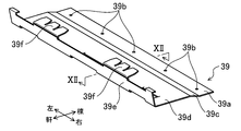
- FIG. 12 is a sectional view taken along line XII-XII in FIG. 11. It is a perspective view around the 1st ridge side cover.
- FIG. 4 is a diagram corresponding to FIG. 3 of a second embodiment.
- FIG. 8 is a diagram corresponding to FIG. 7 of the second embodiment.
- FIG. 9 is a diagram corresponding to FIG. 8 of the second embodiment.
- It is a perspective view of a building material integrated solar cell module and a 1st draining member.
- FIG. 18 is a sectional view corresponding to the line XVIII-XVIII in FIG. 17. It is a perspective view of a 2nd drainer.
- FIG. 19 is a diagram corresponding to FIG. 18 of a first modification of the second embodiment.
- FIG. 19 is a diagram corresponding to FIG. 18 of a first modification of the second embodiment.
- FIG. 19 is a diagram corresponding to FIG. 18 of a second modification of the second embodiment.
- FIG. 1B is a diagram corresponding to FIG. 1B of a third embodiment.
- FIG. 23 is a diagram corresponding to FIG. 22 of a first modification of the third embodiment.
- FIG. 23 is a diagram corresponding to FIG. 22 of a second modification of the third embodiment. It is a perspective view of the three-stage drainer.
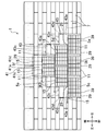
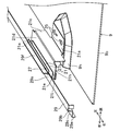
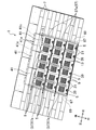
- FIG. 1A and FIG. 1B show one of a pair of roof surfaces 1 constituting a building roof.
- Each roof surface 1 includes a roof foundation 3 composed of a base plate 3a and a waterproof sheet 3b, and the surface of the base plate 3a is entirely covered with a waterproof sheet 3b (see FIG. 10).
- the front side when the roof surface 1 is viewed from the outside that is, the side on which the sun shines is referred to as the front side
- the opposite side is referred to as the back side.
- the direction orthogonal to the eaves ridge direction when viewed from the front side of the roof surface 1 is referred to as the girder direction.
- the right side when viewed from the front side of the roof surface 1
- the left side the left side in FIG. 1A
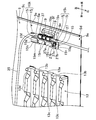
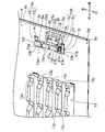
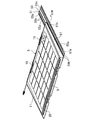
- solar cell modules 5a to 5f Six building material-integrated solar cell modules 5a to 5f (hereinafter simply referred to as solar cell modules) are laid in the center (part) of the roof base 3 surface (the surface of the waterproof sheet 3b) in the girder direction. . More specifically, solar cell modules 5a to 5c are laid in order from the right side at the eave-side end of the surface of the roof base 3 at the center in the girder direction. Then, solar cell modules 5d and 5e are laid in order from the right side on the ridge side of the solar cell modules 5a to 5c, and a solar cell module 5f is laid on the ridge side of these solar cell modules 5d and 5e.
- the solar cell modules 5a to 5f have a common configuration, they are denoted by reference numeral 5 when they do not need to be distinguished.
- a plurality of slate 7 (corresponding to a roof material) is laid in a non-laying area of the solar cell modules 5a to 5f.
- the “solar cell module” in the present application includes a plurality of electrically connected solar cells, which are protected by a sealing material such as a resin. Means a product with an attached.
- each solar cell module 5 has a trapezoidal base plate 9 formed of a plated steel plate as a noncombustible material, and a base plate formed by applying the installation structure according to the embodiment of the present invention. 9 and a solar cell panel 11 disposed on the front side.
- the non-combustible material constituting the base plate metals other than plated steel plates, such as aluminum and stainless steel, may be adopted.
- the solar cell panel 11 is indicated by a two-dot chain line.
- the base plate 9 includes a ridge-side extending portion 9 m that extends toward the ridge side from a ridge-side frame member 15 described later, and at least a beam direction of the solar cell panel 11 in a front view as viewed from the front side. It has a girder-side extending portion 9n extending outward from one end (the left end in FIG. 2).
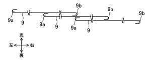
- a left bent portion 9a is formed at one end (left end) in the beam direction of the base plate 9 and is bent in a U-shaped cross section toward the front side.
- the left bent portion 9a functions as a water return for preventing water existing on the base plate 9 from leaking to the left outside.
- a right-side bent portion 9b bent in a U-shaped cross section toward the back side is formed.
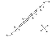
- the ridge-side bent portion 9c As shown in FIG. 4B, at one end of the base plate 9 in the eaves ridge direction (the end on the ridge side), the ridge-side bent portion bent in a U-shaped cross section toward the front side over the entire length excluding the right end. 9c is formed.
- the ridge-side bent portion 9c functions as a water return for preventing water existing on the base plate 9 from leaking outward in the ridge direction.
- an eaves-side bent portion 9j that is bent in a U-shaped cross section toward the back side is formed.
- the solar cell modules 5 when they are also arranged in the eaves ridge direction in the goby fold configuration in the eaves ridge direction, they function as a “water drainage structure” as in the case of FIG. 4A.
- This “water drainage structure” will also be described in detail in the “roof structure” described later.
- the left bent portion 9a and the right bent portion 9b are bent in a U-shaped cross section, but the present invention is not limited to this.
- the left bent portion 9a and the right bent portion 9b may have a shape that is bent in an L-shaped cross section, or may be folded and completely crushed in the front and back directions.
- the ridge-side bent portion 9c and the eave-side bent portion 9j are not limited to a U-shaped cross section, but may be bent or folded in an L-shaped cross section. The shape may be such that it collapses in the front and back directions.
- the eave-side edge (edge) of the base plate 9 extends substantially horizontally, while the ridge-side edge (edge) of the base plate 9 is one side in the girder direction with respect to the eave-side edge. (Right side in FIG. 5). Accordingly, even when the girder ends of the base plates 9 of the solar cell modules 5 arranged adjacent to each other in the girder direction are arranged to overlap each other, the ridge-side bent portions 9c do not overlap each other, and the thickness direction between the base plates 9 is reduced. Is less likely to occur.
- a U-shaped notch 9d is formed at a location adjacent to the ridge-side bent portion 9c at the ridge-side edge of the base plate 9 from the right side.
- six ridge side mounting holes 9e are formed so as to be spaced apart in the girder direction.
- a pair of ridge side bulging portions 9f (see FIG. 2) bulging to the front side are formed at intervals in the girder direction.
- the ridge-side bulging portion 9f has a rectangular shape that is long in the girder direction in plan view.
- the ridge-side bulging portion 9f is formed with a pair of ridge-side screw insertion holes 9g (see FIG. 3) at intervals in the girder direction.
- a pair of eave-side bulges 9h that bulge to the front side and open to the eaves side are provided at positions at the lower end of the base plate 9 that face the ridge-side bulges 9f in the eaves ridge direction (flow direction) (FIG. 2).
- the eave-side bulging portion 9h has a substantially pentagonal shape in plan view, in which the ridge-side end gradually narrows toward the ridge-side, and a region other than the upper end extends in the eave-ridge direction with a constant width. I have.
- a pair of eave-side screw insertion holes 9i are formed in the eave-side bulging portion 9h at intervals in the girder direction.
- the bulging height H1 of the eave-side bulging portion 9h is higher than the bulging height H2 of the ridge-side bulging portion 9f (see FIG. 10).
- each base plate 9 the surface on the side opposite to the roof substrate 3
- two substantially plate-like cushioning materials 13 each having a rectangular shape in plan view are spaced from each other in a state where the plate surfaces are arranged along the surface of the base plate 9. In addition, they are arranged with an interval between the outer peripheral edge of the base plate 9.
- the cushioning material 13 is formed of a resin having at least one of a shock absorbing function and a heat insulating function, such as expanded polystyrene.
- one first back side groove portion 13 a (first groove portion) extending in the eaves ridge direction in a shallow dish shape gradually increasing in width toward the back side in the front and back direction is provided.
- two second back-side grooves 13b (corresponding to the first grooves) are formed at intervals in the beam direction.
- a space portion is formed between the first back side groove portion 13a and the base plate 9 and between the second back side groove portion 13b and the base plate 9 so as to extend in the direction of the eaves ridge with a trapezoidal cross section and allow rainwater or the like to pass therethrough.
- the shape and number arrangement of the first grooves are not particularly limited.
- the shape of the first groove may be another shape such as a semicircular cross section.
- FIG. 6 shows, as an example, an example in which the first back side groove portion 13a is arranged so as to be sandwiched between two second back side groove portions 13b from both sides in the beam direction.
- the first back side groove portion 13a is more than the second back side groove portion 13b from the viewpoint of facilitating the alignment of the center of the cushioning material 13 and the center of the eave-side bulging portion 9h of the base plate 9 in the girder direction.
- first front-side groove portions 13c (corresponding to third groove portions) extending in the entire eaves ridge direction with a shallow dish shape in cross section gradually widening toward the front side in the front-back direction. They are formed spaced apart from each other in the girder direction. Thereby, a space portion having a trapezoidal cross section and extending in the eaves ridge direction is formed between the first front-side groove portion 13c and the solar cell panel 11.
- the surface of the cushioning material 13 has, for example, five non-formation regions of the first front-side groove portions 13c that are long in the eaves ridge direction, and in the non-formation regions, the solar cell panels 11 are in the girder direction and the eaves ridge direction. It supports the middle part. Thereby, the air permeability on the back side of the solar cell panel 11 is secured, and the temperature rise of the solar cell panel 11 is suppressed.
- the number of the non-formation regions of the first front-side groove portion 13c is not limited to five, and may be four or less or six or more depending on the size of the cushioning material 13, for example.
- three second front-side groove portions 13d (corresponding to the second groove portions) extending gradually in the girder direction with a shallow dish shape in cross section gradually widening toward the front side in the front-back direction. ) are spaced from each other in the direction of the eaves ridge. Thereby, a space portion having a trapezoidal cross section and extending in the eave direction is formed between the second front-side groove portion 13d and the solar cell panel 11.
- the shape, number, and arrangement of the grooves formed on the surface of the cushioning material 13 are not limited to the shapes, numbers, and arrangements of the first front-side groove 13c and the second front-side groove 13d as described above.
- the eave-side sidewall of the second front-side groove 13d is inclined in the eave direction toward one of the girder directions (the right side in FIG. 2), 2)
- the depth of the first front groove 13c is greater than the depth of the second front groove 13d.
- a region of the back surface of the cushioning material 13 where the first back side groove portion 13a and the second back side groove portion 13b are not formed is adhered to the surface of the base plate 9 with a double-sided tape.
- a region where the first front-side groove portion 13c and the second front-side groove portion 13d are not formed on the surface of the cushioning material 13 is not bonded to the back surface of the solar cell panel 11.
- a ridge-side frame member 15 (corresponding to a ridge-side support member) made of metal for supporting the ridge-side end of the solar cell panel 11 is provided on each ridge-side bulging portion 9 f of the base plate 9. Installed from the front side with a gap in the direction. At a position corresponding to the ridge-side frame member 15, a rectangular ridge-side auxiliary plate 17 is attached to the back side of each ridge-side bulging portion 9f (see FIG. 3).
- the ridge-side auxiliary plate 17 is formed with a pair of ridge-side fastening holes 17a spaced apart in the longitudinal direction.
- the ridge-side frame member 15 has a rectangular-plate-shaped mounting surface portion 15a extending in the beam direction with one surface thereof abutting on the base plate 9.
- a pair of ridge side screw holes 15b are formed in the mounting surface portion 15a at intervals in the longitudinal direction (girder direction) so as to correspond to the ridge side screw insertion holes 9g of the base plate 9.
- a plate-like standing surface portion 15c is formed integrally with the eave-side edge extending in the longitudinal direction of the mounting surface portion 15a so as to project the plate surface toward the eaves ridge in the front direction of the base plate 9.
- the upright surface portion 15c has a central portion 15d continuous with the same width as the mounting surface portion 15a, and a pair of extending portions 15e extending to both sides in the girder direction from a portion excluding the base end portion of the central portion 15d. It is formed in a substantially T-shape when viewed.
- a first sandwiching wall portion 15f is integrally protruded toward the eaves side at the tip edge of the upright portion 15c, that is, at the edge on the tip side of the upright portion 15c of the central portion 15d and the extension portion 15e.
- a second holding wall 15g as a ridge-side contact surface is opposed to the first holding wall 15f at an end edge on the base end side of the rising surface 15c of each extension 15e, and the first holding wall 15f. They are integrally protruded from the wall 15f so as to project outward on both sides in the girder direction.
- a ridge 15h as a ridge-side protrusion extending in the eaves ridge direction is integrally protruded toward the front side of the second holding wall portion 15g at a position facing both ends in the girder direction of the first holding wall portion 15f. ing.
- An extension wall 15i extending toward the ridge is formed integrally with a portion of the second second holding wall 15g that protrudes outward in the girder direction so as to be flush with the second holding wall 15g.
- a projecting piece 15j is integrally provided at the tip end of the extension wall 15i so as to project toward the front side.
- the extension wall portion 15i and the projecting piece portion 15j constitute a cable hook 15k (corresponding to a holding portion) for holding the cable at a predetermined height position.
- three bent wall portions 15m projecting toward the front side and bending toward the ridge side are integrally provided at intervals in the beam direction.
- Each bent wall portion 15m and the first sandwiching wall portion 15f form a groove 15n as an engaging portion extending in the spar direction and opening to the ridge side.
- the ridge side frame member 15 configured as described above includes a ridge side screw hole 15b of the mounting surface portion 15a of the ridge side frame member 15, a ridge side screw insertion hole 9g of the base plate 9, and a ridge side of the ridge side auxiliary plate 17.
- the screw 19 is fastened to the base plate 9 by inserting a screw 19 into the fastening hole 17a in order from the front side.
- each eave-side bulging portion 9h of the base plate 9 has a metal eave-side frame member 21 (corresponding to an eave-side support member) that supports the eave-side end of the solar cell panel 11. ) Are attached at a position facing the ridge side frame member 15 in the eaves ridge direction at an interval in the girder direction.
- a rectangular eave-side auxiliary plate 23 is attached to the back side of each eave-side bulging portion 9h (see FIG. 3).
- a pair of eave-side fastening holes 23a are formed in the eave-side auxiliary plate 23 at intervals in the longitudinal direction.
- the eaves-side frame member 21 includes a mounting wall 21a having a rectangular plate shape in a plan view and having a long surface extending in the girder direction and having one surface abutting the base plate 9.
- a pair of eave-side screw holes 21b are formed in the mounting wall 21a at intervals in the longitudinal direction (girder direction) so as to correspond to the eave-side screw insertion holes 9i of the base plate 9. I have.
- An eave-side edge of the mounting wall 21a of the base plate 9 is integrally formed with a plate-shaped upright wall 21c that projects in the front direction of the base plate 9 with the plate surface facing the eaves ridge.
- Both ends in the girder direction of the upright wall portion 21c protrude to both outer sides in the girder direction from the mounting wall portion 21a.
- a long plate portion 21d having a substantially rectangular shape in a plan view with the plate surface facing in the front and back directions is formed on the ridge side with both longitudinal ends projecting outward in the girder direction of the standing wall portion 21c. It protrudes integrally toward.
- a pair of plate-like projecting wall portions 21e are integrally provided at both ends in the girder direction of the leading edge of the long plate portion 21d so as to be inclined to the front side toward the eaves side. Therefore, the base end of the protruding wall portion 21e is slightly bent.
- a plate-shaped central wall portion 21f is provided integrally with the protruding wall portion 21e so as to protrude toward the eaves side at a central portion in the girder direction of the leading edge of the long plate portion 21d.
- a pair of frame-side through-holes 21g are formed in the vicinity of the front end of the center wall 21f at intervals in the beam direction.
- a plate-shaped step forming surface portion 21h is integrally protruded toward the back side between the protruding portion of the protruding wall portion 21e and the protruding portion of the central wall portion 21f at the distal end edge of the long plate portion 21d.
- a projecting piece 21i extending in the girder direction and projecting toward the eaves side is integrally provided at the tip of the step forming surface portion 21h.
- the relative positions of the projecting pieces 21i of the right eaves-side frame member 21 and the grooves 15n of the right ridge-side frame member 15 in the girder direction with respect to the solar cell panel 11 are equal to each other.
- the relative positions of the groove 21n of the piece 21i and the groove 15n of the left ridge side frame member 15 with respect to the solar cell panel 11 in the girder direction are also equal to each other.
- the eaves-side frame member 21 configured as described above includes the eaves-side screw hole 21b of the mounting wall 21a of the eaves-side frame member 21, the eaves-side screw insertion hole 9i of the base plate 9, and the eaves of the eaves-side auxiliary plate 23.
- the screws 25 are fastened to the base plate 9 by sequentially inserting the screws 25 into the side fastening holes 23a from the front side.
- the solar cell panel 11 has a rectangular plate shape and is installed with its longitudinal direction facing the girder direction.
- the front and back surfaces of the solar cell panel 11 are inclined so as to be separated from the surface of the base plate 9 toward the eaves side.
- the solar cell panel 11 sequentially forms a transparent electrode layer such as tin oxide, an optical semiconductor layer, and a back electrode layer such as a metal on the back surface of a 551 ⁇ 908 mm horizontally long rectangular glass substrate, and these layers are subjected to laser processing or the like.
- a filler such as EVA (ethylene-vinyl acetate copolymer), polyolefin, glass, a PET film, or a Tedlar film is used. It is formed by sealing and protecting the element forming surface side.
- the gasket 27 includes a long plate-like connecting wall 27a and a pair of long plate-like opposing walls 27b protruding from both ends extending in the longitudinal direction of the connecting wall 27a.
- a pair of ribs 27c extending in the longitudinal direction of the connecting wall portion 27a are provided on the surface of the connecting wall portion 27a on the side opposite to the opposing wall portion 27b so as to be spaced apart from each other.
- the two opposing walls 27b of the gasket 27 sandwich the ridge-side end of the solar cell panel 11 from both sides in the thickness direction.
- the first holding wall 15f and the second holding wall 15g of the ridge side frame member 15 hold the gasket 27 and the ridge side end of the solar cell panel 11. Therefore, the second sandwiching wall 15 g of the ridge side frame member 15 is in contact with the gasket 27 from the back of the solar cell panel 11.
- the ridge 15h (see FIG. 7 and the like) of the ridge side frame member 15 protrudes from the second sandwiching wall 15g in the front direction of the solar cell panel 11 and faces the gasket 27 from both outer sides in the beam direction. The movement of the gasket 27 in the beam direction is restricted.
- the upright surface 15 c of the ridge side frame member 15 is in contact with both ribs 27 c of the gasket 27 from the ridge side.
- the groove 15n of the ridge-side frame member 15 is located on the front side of the ridge-side end of the solar cell panel 11 to which the ridge-side frame member 15 is attached. In this manner, the pair of ridge-side frame members 15 mounted on the common base plate 9 are mounted on the ridge-side end of the solar cell panel 11 with a space therebetween in the girder direction via the gasket 27. .
- a pair of gaskets 27 as a pair of eave-side holding members are attached to the eave-side end of each solar cell panel 11 at intervals in the girder direction.
- the base end of the central wall portion 21f of the eaves-side frame member 21 is in contact with the gasket 27 from the back of the solar cell panel 11. Therefore, the projecting piece 21i of the eaves-side frame member 21 is located behind the eaves-side end of the solar cell panel 11 to which the eaves-side frame member 21 is attached.
- the protruding wall portions 21e of the eaves side frame member 21 project in the front direction of the solar cell panel 11 beyond the central wall portion 21f on both outer sides in the beam direction of the central wall portion 21f and face the gasket 27 from both outer sides in the beam direction.
- the movement of the gasket 27 in the girder direction is restricted.
- an elongate cover member 29 is provided on the opposing wall 27b on the front side of the solar cell panel 11 of the gasket 27 attached to the eaves side end of each solar cell panel 11. Is mounted so as to cover the entire length.
- the cover member 29 is opposed to the eaves-side end of the solar cell panel 11 from the front side and covers the eaves-side end over the entire length, and a long plate-shaped first surface 29a, and the eaves-side of the first surface 29a.
- a long plate-like second surface portion 29b extending from the edge to the back side and covering the eaves-side end surface of the solar cell panel 11 over the entire length, and a length extending from the back-side edge of the second surface portion 29b to the eaves side.
- a plate-shaped third surface portion 29c is provided.
- a pair of cover-side through-holes 29d are formed at intervals in the longitudinal direction in the gasket 27 attachment region of the third surface portion 29c.
- a long plate-like fourth surface portion 29e extending in the back direction of the solar cell panel 11 is formed at an eave-side edge of a portion of the third surface portion 29c other than the gasket 27 attachment region.
- the cover member 29 configured as described above is screwed into the cover-side through-hole 29d of the third surface portion 29c of the cover member 29 and the frame-side through-hole 21g of the eaves-side frame member 21 in order from the front side of the solar cell panel 11. Is fastened to the eaves-side frame member 21. In this manner, the pair of eaves-side frame members 21 attached to the common base plate 9 are attached to the eaves-side end of the solar cell panel 11 with the gasket 27 spaced apart from each other in the girder direction. .
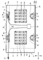
- a terminal box 33 is provided on the surface of the base plate 9 at a position closer to the eaves than the cushioning material 13 and between the cushioning materials 13 in the beam direction.
- the terminal box 33 houses the base ends of a pair of cables 35, and a connector 37 is connected to the end of each cable 35.
- the connector 37 is used for connection with the connector 37 of the adjacent solar cell module 5 and connection with a connector (not shown) of a cable drawn from a power conditioner (not shown).
- the cable 35 is held by the cable hook 15k such that the connector 37 connected to the distal end is disposed near the cable hook 15k.
- one cable 35 (for example, a right cable, hereinafter also referred to as a “right cable 35”) is configured such that the vicinity of the distal end abuts on the front side of the left cable hook 15 k of the right ridge side frame member 15. By being placed, it is held at a predetermined height position. At this time, the connector 37 of the right cable 35 is located on the ridge side of the extension 15e of the ridge side frame member 15.
- the other cable 35 (for example, a left cable, hereinafter also referred to as a “left cable 35”) has an intermediate portion in the longitudinal direction held by the cable hook 15k of the left ridge side frame member 15. Specifically, the left cable 35 passes through the lower side of the left cable hook 15k via the lower side of the right cable hook 15k of the left ridge side frame member 15, so that the middle part in the longitudinal direction is predetermined. Is held at the height position.
- the left cable 35 extends toward the ridge side frame member 1 on the right side of the solar cell module 5 adjacent on the left side.
- the connector 37 of the left cable 35 is connected to the connector 37 of the right cable 35 of the solar cell module 5 adjacent on the left.
- the vicinity of the distal end of the left cable 35 is placed so as to abut the front side of the right cable hook 15k of the right ridge side frame member 15 of the solar cell module 5 adjacent to the left (see FIG. 6).
- the connector of the left cable 35 is held at the predetermined height position.
- the connector 37 of the left cable 35 is located on the ridge side of the extension 15e of the ridge side frame member 15.
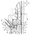
- the ridge side of the extension portion 15e of the ridge side frame member 15 is covered by the standing wall portion 21c and the long plate portion 21d of the eave side frame member 21 of the solar cell module 5 adjacent to the ridge side (see FIG. 10). ). Thereby, the connection part between the connectors 37 of the left cable 35 and the right cable 35 of the adjacent solar cell module 5 is protected from intrusion of water, dust and the like from the front direction and the eaves building direction.
- a roof structure (hereinafter simply referred to as a roof structure) formed by laying and arranging solar cell modules 5 integrated with building materials.
- the position of the solar cell panel 11 in which the back surface of the base plate 9 is in contact with the surface of the roof base 3 (the waterproof sheet 3b) and the adjacent solar cell panel 11 is in the girder direction. Are laid side by side so as to be shifted by 1/2.
- the left half of the solar cell panel 11 of the solar cell module 5a is adjacent to the right half of the solar cell panel 11 of the solar cell module 5d from the eaves side, and the right half of the solar cell panel 11 of the solar cell module 5b. Is adjacent to the left half of the solar cell panel 11 of the solar cell module 5d from the eaves side.
- the left half of the solar cell panel 11 of the solar cell module 5b is adjacent to the right half of the solar cell panel 11 of the solar cell module 5e from the eaves side
- the right half of the solar cell panel 11 of the solar cell module 5c is The solar cell module 5e is adjacent to the left half of the solar cell panel 11 from the eaves side.
- the left half of the solar cell panel 11 of the solar cell module 5d is adjacent to the right half of the solar cell module 5f from the eaves side, and the right half of the solar cell panel 11 of the solar cell module 5e is located on the left half of the solar cell module 5f. Adjacent from the eaves side.
- the eaves-side bulging portion 9h of the base plate 9 of the ridge-side solar cell modules 5d to 5f is connected to the eaves-side solar cell module.
- the ridge-side bulging portion 9f of the base plate 9 of 5a to 5e overlaps from the front side of the base plate 9.
- the ridge side attached to a portion adjacent to the ridge side solar cell panel 11 in the eaves side solar cell panel 11.
- a protruding piece 21i of the eave-side frame member 21 attached to a portion adjacent to the eave-side solar cell panel 11 in the ridge-side solar cell panel 11 is inserted and engaged. . Therefore, the solar cell panel of the solar cell module 5e is provided in the groove 15n of the right ridge side frame member 15 of the solar cell panel 11 of the solar cell module 5b adjacent to the solar cell panel 11 of the solar cell modules 5d and 5e from the eaves side.
- the projecting piece 21i of the left eave-side frame member 21 of the solar cell module 11 is inserted into and engaged with the groove 15n of the left ridge-side frame member 15 of the solar cell panel 11 of the solar cell module 5b.
- the projecting piece 21i of the right side eave-side frame member 21 of the battery panel 11 is inserted and engaged.
- the eave-side members 39 shown in FIGS. 11 and 12 are attached to the eave-side frame members 21 of the solar cell modules 5a to 5c having no solar cell module 5 adjacent to the eaves side.
- the eaves side member 39 has a long plate-shaped mounting plate portion 39a that extends in the beam direction with one surface thereof abutting on the waterproof sheet 3b.
- Five eave-side mounting holes 39b are formed in the mounting plate portion 39a at intervals in the beam direction.
- the eaves-side member 39 is fixed to the roof foundation 3 by inserting screws (not shown) into the eaves-side mounting holes 39b, the waterproof sheet 3b, and the roof foundation 3 and fastening them.
- an inclined plate portion 39c that is inclined toward the eaves side toward the front surface of the roof base 3 is extended with the same length in the girder direction as the mounting plate portion 39a,
- an extension plate portion 39d extending substantially parallel to the mounting plate portion 39a is provided to extend in the same direction as the mounting plate portion 39a in the beam direction.
- an upright plate portion 39e is erected toward the roof base 3 front side.
- a pair of plate-shaped insertion portions 39f whose plate surfaces face the front and back sides of the roof foundation 3 are provided at the tip of the standing plate portion 39e so as to protrude toward the ridge side with a space therebetween in the girder direction.
- These insertion portions 39f are opposed to the projecting pieces 21i of the eaves-side frame member 21 from the front side of the base plate 9 to restrict the movement of the eaves-side frame member 21 to the front side of the base plate 9, and to control the center wall of the eaves-side frame member 21.
- the movement of the eaves side frame member 21 to the back side is regulated so as to face the base plate 9 from the back side to 21f. Therefore, wobble of the eaves side frame member 21 in the front and back directions is prevented.
- the first building-side cover 41 is provided on the solar cell panel 11 without the solar cell panel 11 adjacent to the ridge side, that is, on the ridge side of the solar cell panel 11 of the solar cell module 5f.
- the first building side cover 41 includes a first main surface portion 41a in a plate shape and a first building side plate portion 41d located on the ridge side with respect to the first main surface portion 41a.
- the first main surface portion 41a covers the roof base 3 (waterproof sheet 3b) on the ridge side of the solar cell module 5f from the front side.
- the first ridge side plate portion 41d located on the ridge side of the first main surface portion 41a is covered from the front side by the slate 7 arranged on the ridge side of the first ridge side cover 41 (see FIG. 1A).
- FIG. 1A In FIG.
- a first side surface portion 41b is provided on both ends in the beam direction of the first main surface portion 41a so as to project toward the back side.
- Four screw holes 41c are formed in the first ridge side plate portion 41d of the first main surface portion 41a of the first ridge side cover 41 at intervals in the girder direction.
- the first ridge side plate portion 41d of the first ridge side cover 41 and the slate 7 are fixed to the roof foundation 3 by inserting and fastening screws (not shown) to these screw holes 41c and the roof foundation 3. (Joined).
- the eave-side end of the first main surface portion 41a of the first ridge side cover 41 is inserted into and engaged with the groove 15n of the ridge side frame member 15 of the solar cell module 5f. ing.
- the second building side is located on the ridge side of the portion adjacent to the slate 7 of the solar cell panel 11 (solar cell panels 11 of the solar cell modules 5a, 5c, 5d, 5e) in which the half in the beam direction is adjacent to the slate 7 from the eaves side.
- a cover 43 is provided.
- the second ridge side cover 43 includes a plate-shaped second main surface portion 43a and a second ridge side plate portion 43d located on the ridge side with respect to the second main surface portion 43a.
- the second main surface 43a covers the roof base 3 (waterproof sheet 3b) on the ridge side of the solar cell module 5 (for example, the solar cell modules 5a, 5c, 5d, 5e) adjacent from the eaves side from the front side.
- the second ridge side plate portion 43d located on the ridge side of the second main surface portion 43a is covered from the front side by the slate 7 arranged on the ridge side of the second ridge side cover 43 (see FIG. 1A).
- a second side surface portion 43b is provided on both ends in the beam direction of the second main surface portion 43a so as to project rearward.
- Two screw holes 43c are formed in the second ridge side plate portion 43d of the second main surface portion 43a of the second ridge side cover 43 at intervals in the girder direction. The screws (not shown) are inserted into these screw holes 43c and the roof foundation 3 and fastened, whereby the second building side plate portion 43d of the second building side cover 43 and the slate 7 are fixed to the roof foundation 3. (Joined).
- the eaves-side end of the second main surface portion 43a of the second building-side cover 43 is connected to the building-side frame member 15 attached to the slate adjacent portion of the solar cell panel 11 of the solar cell modules 5a, 5c, 5d, 5e. It is inserted into the groove 15n.
- the right solar cell module 5b On the front side of the girder-side extending portion 9n of the base plates 9 of 5c and 5e (hereinafter referred to as right base plate 9), right end portions of the base plates 9 of left solar cell modules 5a, 5b and 5d (hereinafter referred to as left base plate 9).
- right base plate 9 On the front side of the girder-side extending portion 9n of the base plates 9 of 5c and 5e (hereinafter referred to as right base plate 9), right end portions of the base plates 9 of left solar cell modules 5a, 5b and 5d (hereinafter referred to as left base plate 9).
- left base plate 9 right bent portion 9b of the left base plate 9 is laid on the front side of the left bent portion 9a of the right base plate 9 so as to overlap.
- the left bent portion 9a and the ridge-side bent portion 9c of the base plate 9 are bent in a U-shaped cross section toward the front side and function as a water return. Even if water enters from the boundary portion, the surface of the roof foundation 3 does not flood.
- the base plates 9 of the solar cell modules 5 d and 5 e on the eave side (hereinafter, referred to as eaves side base plate 9) among the two solar cell modules 5 arranged adjacent to each other in the eaves ridge direction.
- the eaves-side end of the base plate 9 (hereinafter referred to as the ridge-side base plate 9) of the ridge-side solar cell module 5f overlaps the front side of the ridge-side extension 9m.
- the eave-side bent portion 9j of the ridge-side base plate 9 is laid on the front side of the ridge-side bent portion 9c of the eave-side base plate 9 so as to overlap.
- the ridge-side bent portion 9c of the base plate 9 is bent in a U-shaped cross section toward the front side and functions as a water return, so that water flows from the boundary portion of the base plate 9 adjacently arranged in the eaves ridge direction. Even if it enters, the surface of the roof foundation 3 does not flood.
- the overlapping width W2 of the base plates 9 of the solar cell modules 5 adjacent in the eaves ridge direction is wider than the amount of water entering due to the capillary phenomenon. From the viewpoint of setting the distance, it is preferable to set the distance to 50 mm or more. As a result, even if water intrudes from the boundary between the base plates 9 arranged adjacent to each other in the eaves ridge direction, the water does not reach the ridge side end of the eaves-side base plate 9.
- a long drainer that extends over the entire length of the boundary between the base plate 9 of the solar cell module 5 and the slate 7 that is adjacent to the base plate 9 in the girder direction is provided.
- a plate 45 (corresponding to a draining member) is provided.
- each draining plate 45 located on the right side of the base plate 9 of the building material-integrated solar cell module 5a, 5d, 5f is located on the back side of the base plate 9 and on the front side of the waterproof sheet 3b.
- the right part of each draining plate 45 located on the right side of the base plate 9 is located on the back side of the slate 7 and on the front side of the waterproof sheet 3b.
- each draining plate 45 located on the left side of the base plate 9 of the building material integrated solar cell modules 5c, 5e, 5f is located on the front side of the base plate 9 and on the back side of the solar cell panel 11.
- the left side portion of each draining plate 45 located on the left side of the base plate 9 is located on the front side of the base plate 9 and on the back side of the slate 7.
- the area of the draining plate 45 overlapping the first building-side cover 41 or the second building-side cover 43 is located on the back side of the first building-side cover 41 or the second building-side cover 43 and on the front side of the waterproof sheet 3b. .
- the building material-integrated solar cell modules 5a to 5f are laid in a state where the entire surface of the roof foundation 3 is covered with the waterproof sheet 3b.
- 5d, and 5f are laid so that the left part thereof is sandwiched between the base plate 9 of the building material-integrated solar cell modules 5a, 5d, and 5f and the waterproof sheet 3b, and the building material-integrated solar cell module 5c , 5e, 5f are laid so that the right side thereof is located on the surface side of the base plate 9 of the building material integrated solar cell module 5c, 5e, 5f, and finally the slate 7 is laid.
- the draining plate 45 is provided with a ridge-side extension portion 45a extending toward the ridge side from the ridge-side edge of the base plate 9.
- the ridge-side extension portion 45a extends to the boundary between the slate 7 and the second ridge-side cover 43 arranged side by side in the girder direction. Then, both ends in the girder direction of the draining plate 45 including the ridge-side extension portion 45a are bent in a U-shaped cross section toward the front side, and have a function as a water return.
- the water that has entered the boundary between the slate 7 and the boundary between the slate 7 and the second building-side cover 43 that are adjacent to the base plate 9 in the girder direction is caused to flow toward the eaves ridge by the drain plate 45.
- there is a water return there is no possibility that water will enter the base plate 3a from the end in the girder direction of the drain plate 45.
- the base plate 9 of the solar cell module 5 adjacent in the eaves ridge direction includes the ridge side frame member 15 of the solar cell module 5 located on the eave side and the eaves side frame member 21 of the solar cell module 5 located on the ridge side. Are configured to conduct with each other when they are engaged. Therefore, the solar cell modules 5 adjacent in the eaves ridge direction are also grounded.
- the cable 35 pulled out from the back surface side of the solar cell panel 11 is wired on the front side of the base plate 9 formed of a noncombustible material such as metal. That is, since the base plate 9 is interposed between the cable 35, the connector 37 and the like and the roof base 3, safety such as fire prevention performance is high.
- a cable hook 15k for holding the cable 35 at a predetermined height position is provided on the ridge side of the ridge side frame member 15, and the cable connector 37 is arranged near the cable hook 15k. Thereby, the distance between the cable connector 37 and the base plate 9 is ensured, and safety such as fire prevention performance is high.
- a goby fold structure is adopted in the girder direction and the eaves ridge direction of the base plate 9, it can function as a draining structure.
- the solar cell modules 5 are laid side by side, when the solar cell modules 5 are laid one on top of the other so that the end of the side bent toward the front side is on the back side, water entering from the boundary between the adjacent solar cell modules 5 can be obtained. As a result, the roof base 3 is not flooded.
- the cushioning members 13 are discretely arranged, and grooves are formed on the front and back surfaces of the cushioning members 13 so as to extend in the entire eaves ridge direction. Further, on the surface of the cushioning material 13, a second front-side groove portion 13d extending to a region where the first front-side groove portion 13c is not formed is formed. Thereby, a space is formed between the first and second front-side grooves 13c and the solar cell panel 11, and between the first and second back-side grooves 13a and 13b and the base plate 9. Thereby, ventilation, drainage, and a cable wiring area are secured.
- the ridge side of the base plate 9 is inclined in one of the eave ridge directions with respect to the eave side, when the solar cell modules 5 are laid side by side in the girder direction, the end of the base plate 9 is Even when the portions overlap each other, the water return structures (the U-shaped folded portions) of the adjacent base plates 9 are alternately arranged, and therefore do not overlap.
- FIG. 14 is a diagram corresponding to FIG. 3 of the second embodiment.
- the second embodiment in the middle of the eaves ridge direction of the base plate 9, four reinforcing swelling portions 9 k having a long shape in the eaves ridge direction and bulging to the back side are formed at intervals in the girder direction. Have been.
- a ground hole 15p as a circular connecting portion is formed through the distal end of each extension wall 15i of the ridge side frame member 15.
- one bent wall portion 15m of the ridge side frame member 15 is protrudingly provided only at both ends in the girder direction of the leading edge of the first sandwiching wall portion 15f.
- a notch 15q is formed at a position slightly inward from both ends in the girder direction of the first holding wall 15f of the ridge side frame member 15, the extension 15e of the upright surface 15c, and the second holding wall 15g.
- An elongated protruding piece 15r protruding in the ridge direction is formed on an edge of the notch 15q on the first holding wall 15f side.
- a tip bent portion 15s bent toward the base plate 9 is formed at the tip of the protruding piece 15r.
- the protruding piece 15r is formed by cutting and bending a portion corresponding to the notch 15q.
- a round hole terminal 47 a attached to the end of the earth wire 47 is fastened to the earth hole 15 p of the ridge side frame member 15 attached to the two solar cell panels 11 adjacent in the eaves ridge direction with the screw 49.
- the periphery of the ground hole 15p of the ridge-side frame member 15 attached to both solar cell panels 11 is connected via the ground wire 47, and the solar cell panels 11 adjacent in the eaves ridge direction are electrically connected.
- a rectangular plate-shaped snow stopper that extends in the girder direction with its plate surface facing the eaves ridge is provided at the ridge side end of the gasket 27 attachment area of the first surface portion 29 a of the cover member 29.
- 29f is integrally provided.
- FIG. 16 illustrates an example in which the snow stopper 29f is provided on the cover member 29, the snow stopper 29f may not be provided. Further, the cover member 29 may be provided on only a part of the plurality of cover members 29. The same applies to other embodiments and modifications.
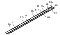
- a long first drainer 51 shown in FIG. is provided at the boundary between the base plate 9 of the building material integrated solar cell module 5d to 5f which is not located at the eave side end and the slate 7 adjacent to the base plate 9 in the girder direction.
- a second drainer 53 in the form of a scale is provided.
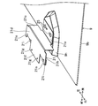
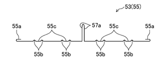
- Each of the drainers 51 and 53 includes a long plate-shaped (including substantially long plate-shaped) main body member 55, and both ends in the width direction of the main body member 55 extend over the entire longitudinal direction except the other end in the longitudinal direction.
- a folded portion 55a having a U-shaped cross section that is folded inward in the width direction on one surface side is formed.
- the main body member 55 has four pairs of bent portions 55b which are bent in a substantially V-shaped cross section so as to protrude toward the one surface side and are adjacent to each other at short intervals in the width direction. They are formed over the entire longitudinal direction at equal intervals.
- the two bent portions 55b forming each pair and the main body member 55 between the two bent portions 55b form a groove 55c extending in the longitudinal direction.
- the main body member 55 is configured by bending one plate.
- a protruding member 57 is fixed to the central portion in the width direction of the one surface of the main body member 55 over the entire length excluding one longitudinal end thereof.
- the protruding member 57 is configured by bending one plate.
- the protruding member 57 includes a pair of trapezoidal plate portions 57a facing each other, and each trapezoidal plate portion 57a has an equal trapezoidal shape that gradually becomes wider from one end in the longitudinal direction to the other end in plan view. .
- One end in the width direction of both trapezoidal plate portions 57a is connected to each other, while the other end in the width direction of both trapezoidal plate portions 57a is formed so as to protrude in the direction away from each other.
- the overhanging plate portion 57b is positioned at the center in the width direction of the one surface of the main body member 55 in a state where the narrow side of the trapezoidal plate portion 57a faces the one end side in the longitudinal direction of the main body member 55.
- the main body member 55 is fixed by caulking over the entire length excluding one end in the longitudinal direction.
- a cutout recess 57c is formed so as to be recessed to the narrow side, while the first draining member 51 has Notch recess 57c is not formed.
- each of the drainers 51 and 53 configured as described above except for one end in the longitudinal direction of the main body member 55 (the area where the protruding member 57 is not provided) is connected to the surface of the base plate 9 (the surface of the roof base 3). ), It straddles the boundary between the base plate 9 of the building material-integrated solar cell modules 5a, 5c to 5f and the slate 7 adjacent to the base plate 9 in the girder direction.
- the trapezoidal plate portions 57a of the drainers 51 and 53 project to the front side at positions corresponding to the boundaries between the base plate 9 and the slate 7.
- both trapezoidal plate portions 57 a are inclined with respect to the surface of the base plate 9 so as to be along the surface of the solar cell panel 11, and approach the edge of the solar cell panel 11. Further, the tips of the two trapezoidal plate portions 57a are formed so as not to protrude from the surface of the solar cell panel 11.
- the left portions of the drainers 51, 53 located on the right side of the base plate 9 of the building material integrated solar cell modules 5a, 5d, 5f are on the back side of the base plate 9 and It is located on the front side of the waterproof sheet 3b.
- the right portions of the drainers 51 and 53 located on the right side of the base plate 9 are located on the back side of the slate 7 and on the front side of the waterproof sheet 3b.
- the right-side portions of the drainers 51, 53 located on the left side of the base plate 9 of the building material-integrated solar cell modules 5c, 5e, 5f are located on the front side of the base plate 9 and on the back side of the solar cell panel 11.
- the left portions of the drainers 51 and 53 located on the left side of the base plate 9 are located on the front side of the base plate 9 and on the back side of the slate 7.
- one end of the main body member 55 of each of the drainers 51 and 53 in the longitudinal direction extends toward the ridge side from the boundary between the base plate 9 and the slate 7.
- a region of one end in the longitudinal direction of the main body member 55 of each of the drainage members 51 and 53 overlaps with the first ridge side cover 41 or the second ridge side cover 43 on the back side of the first ridge side cover 41 or the second ridge side cover 43. And it is located on the front side of the waterproof sheet 3b.
- the ground hole 15p is provided in the ridge side frame member 15, the number of parts can be reduced as compared with a case where a member for providing the ground hole 15p is provided separately from the ridge side frame member 15.
- the snow stopper 29f is provided integrally with the cover member 29, the number of components can be reduced as compared with the case where snow stopper parts are provided separately from the snow stopper 29f. In addition, since it is not necessary to attach the snow stopper to the cover member 29 or the solar cell panel 11, the construction can be facilitated.
- the trapezoidal plate portion 57a is provided on each of the drainers 51 and 53, it is possible to prevent water, insects, and small animals from entering the back side of the solar cell panel 11 from the outside in the girder direction.
- the slate 7 when the slate 7 is laid, the slate 7 can be positioned in the girder direction by contacting the girder edge of the slate 7 with the trapezoidal plate portion 57a of each of the drainers 51, 53.
- each of the draining members 51 and 53 is constituted by the main body member 55 and the protruding member 57, the size of the plate to be bent is smaller than when the entire draining members 51 and 53 are constituted by one member. Since it can be made small and easy to carry, bending work becomes easy. Further, the utilization rate of the material in the punching process of the constituent members of the drainers 51 and 53 can be increased.
- the folded portion 55a of each of the draining members 51 and 53 suppresses the water attached to the inside in the width direction from the folded portion 55a of each of the drainage members 51 and 53 from spreading to the outside in the width direction, Intrusion of water into the back side of 53 is suppressed.
- FIG. 20 is a diagram corresponding to FIG. 18 of the first modification of the second embodiment.
- each of the drainers 51 and 53 instead of the main body member 55, each of the drainers 51 and 53 includes a left drainer 59 and a right drainer 61 disposed adjacent to the left drainer 59 from the right.
- the left-side draining component 59 and the right-side draining component 61 each have a substantially long plate-shaped main plate portion 63.
- the bent portions 55b are formed in the widthwise middle portion of each main plate portion 63 at intervals in the width direction by two pairs.
- the folded portion 55 a is formed at the left end of the main plate 63 of the left drainage component 59 and at the right end of the main plate 63 of the right drainage component 61.
- a projecting wall 65 is provided on the right edge of the left draining member 59 and the left edge of the right draining member 61 over the entire longitudinal direction excluding the ridge side end.
- the projecting member 57 is not formed with the overhanging plate portion 57b, the left trapezoidal plate portion 57a is swaged and fixed to the protruding wall portion 65 of the left drainage component member 59, and the right trapezoidal plate portion 57a is fixed to the right drainage portion. It is caulked and fixed to the projecting wall 65 of the component member 61.
- FIG. 21 is a diagram corresponding to FIG. 18 of the second modification of the second embodiment.
- each of the drainers 51 and 53 is configured by only one member of the main body member 55.
- the trapezoidal plate portion 57a is formed by bending a central portion in the width direction of the main body member 55.
- FIG. 22 is a diagram corresponding to FIG. 1B of the third embodiment.
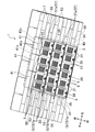
- the building material-integrated solar cell modules 5 are arranged on the roof surface 1 in three rows and three columns.
- the eaves-side end portion (the area where the folded portion 55a is not formed) of the ridge-side drainage member 53 is the main body member 55 of the eaves-side drainage members 51 and 53. It overlaps the ridge side end (the area where the protruding member 57 is not disposed) from the front side.
- the widthwise both ends of the eaves-side draining members 53 of the ridge side are restricted from moving to the front side by the folded-back portions 55a of the ridge-side ends of the main body members 55 of the eaves-side drainers 51 and 53. .
- the draining members 51 and 53 adjacent to each other in the eaves ridge direction since the eaves-side end of the draining member 53 on the ridge side is not formed with the folded portion 55a, the folded portion 55a is not formed.
- the eaves-side end of the ridge-side draining member 53 can be more easily overlapped with the ridge-side ends of the eaves-side drainers 51 and 53 from the front side than in the case of forming the 55a.
- FIG. 23 is a diagram corresponding to FIG. 22 of the first modification of the third embodiment.
- the main body member 55 is formed in a shape of an equal-leg trapezoidal plate that gradually becomes wider toward the ridge side. Further, the folded portion 55a is formed over the entire longitudinal direction of both ends in the width direction of the main body member 55.
- the eaves-side end of the ridge-side drainage member 53 is connected to the main body member 55 of the eaves-side drainage members 51 and 53. Since the width is narrower than the ridge-side end, the eave-side end of the ridge-side drainer 53 can be easily overlapped with the ridge-side end of the eave-side drainer 51, 53 from the front side.
- FIG. 24 is a diagram corresponding to FIG. 22 of a second modification of the third embodiment.
- a long three-stage drainage member 67 shown in FIG. 25 is disposed with its longitudinal direction facing the eaves ridge direction.
- the three-stage draining member 67 includes a substantially long plate-shaped main body member 69 whose plate surface is aligned with the surface of the base plate 9 (the surface of the roof base 3).
- three projecting members 57 cause the trapezoidal plate portions 57a to protrude to the front side, and the narrow side of the trapezoidal plate portions 57a to the ridge side. They are fixed so that they are adjacent to each other in the eaves ridge direction.
- the folded portion 55a and the bent portion 55b are formed in the main body member 69 over the entire longitudinal direction.
- the work of stacking the three drainers 51 and 53 on each other is not required, so that the construction work can be facilitated.
- the roof structure is a ridge roof
- the technology of the present disclosure can be applied to a gable roof, and similar effects can be obtained.
- the solar cell panels are laid with the positions in the beam direction aligned, but the same solar cell module 5 as in the above embodiment can be applied.
Landscapes
- Engineering & Computer Science (AREA)
- Architecture (AREA)
- Civil Engineering (AREA)
- Structural Engineering (AREA)
- Roof Covering Using Slabs Or Stiff Sheets (AREA)
- Photovoltaic Devices (AREA)
Abstract
La présente invention concerne un module de cellule solaire intégré à un matériau de construction (5) comprenant : un panneau de cellules solaires (11) ; un matériau d'amortissement (13) disposé sur le côté de surface arrière du panneau de cellules solaires (11) ; une plaque de base (9) qui supporte le matériau d'amortissement (13) et qui est formée à partir d'un matériau incombustible ; et un câble (35) qui est étendu depuis le côté de surface arrière du panneau de cellules solaires (11) et qui est câblé sur le côté avant de la plaque de base (9).
Priority Applications (2)
| Application Number | Priority Date | Filing Date | Title |
|---|---|---|---|
| JP2020546801A JP7364579B2 (ja) | 2018-09-10 | 2019-08-21 | 建材一体型太陽電池モジュール及びそれを備えた屋根構造 |
| US17/196,726 US11463041B2 (en) | 2018-09-10 | 2021-03-09 | Building material-integrated solar cell module and roof structure provided with same |
Applications Claiming Priority (4)
| Application Number | Priority Date | Filing Date | Title |
|---|---|---|---|
| JP2018-168590 | 2018-09-10 | ||
| JP2018168590 | 2018-09-10 | ||
| JP2019-073954 | 2019-04-09 | ||
| JP2019073954 | 2019-04-09 |
Related Child Applications (1)
| Application Number | Title | Priority Date | Filing Date |
|---|---|---|---|
| US17/196,726 Continuation US11463041B2 (en) | 2018-09-10 | 2021-03-09 | Building material-integrated solar cell module and roof structure provided with same |
Publications (1)
| Publication Number | Publication Date |
|---|---|
| WO2020054338A1 true WO2020054338A1 (fr) | 2020-03-19 |
Family
ID=69777496
Family Applications (1)
| Application Number | Title | Priority Date | Filing Date |
|---|---|---|---|
| PCT/JP2019/032625 Ceased WO2020054338A1 (fr) | 2018-09-10 | 2019-08-21 | Module de cellule solaire intégré à un matériau de construction et structure de toit équipée de celui-ci |
Country Status (3)
| Country | Link |
|---|---|
| US (1) | US11463041B2 (fr) |
| JP (1) | JP7364579B2 (fr) |
| WO (1) | WO2020054338A1 (fr) |
Families Citing this family (1)
| Publication number | Priority date | Publication date | Assignee | Title |
|---|---|---|---|---|
| JP7818377B2 (ja) * | 2021-10-28 | 2026-02-20 | 株式会社カネカ | 棟辺カバー |
Citations (5)
| Publication number | Priority date | Publication date | Assignee | Title |
|---|---|---|---|---|
| JP2002115372A (ja) * | 2000-10-10 | 2002-04-19 | Kanegafuchi Chem Ind Co Ltd | 太陽電池モジュール瓦 |
| JP2005518486A (ja) * | 2002-02-20 | 2005-06-23 | パワーライト・コーポレイション | 屋根板システム及び方法 |
| US20120210660A1 (en) * | 2010-12-31 | 2012-08-23 | Livsey Robert D | Roofing Product with Integrated Photovoltaic Elements and Flashing System |
| US20140157694A1 (en) * | 2009-03-24 | 2014-06-12 | Certainteed Corporation | Photovoltaic systems, methods for installing photovoltaic systems, and kits for installing photovoltaic systems |
| US20140259973A1 (en) * | 2013-03-15 | 2014-09-18 | Certainteed Corporation | Roofing Flashings And Roofing Systems And Photovoltaic Roofing Systems Using The Same |
Family Cites Families (23)
| Publication number | Priority date | Publication date | Assignee | Title |
|---|---|---|---|---|
| JPH09107119A (ja) * | 1995-10-11 | 1997-04-22 | Canon Inc | 太陽電池モジュール及び製造法 |
| JPH11159090A (ja) * | 1997-11-27 | 1999-06-15 | Canon Inc | 太陽電池屋根およびその施工方法 |
| JP2000269535A (ja) * | 1999-01-14 | 2000-09-29 | Canon Inc | 太陽電池モジュール、発電装置、太陽電池モジュールの分離方法及び太陽電池モジュールの再生方法 |
| JP4044237B2 (ja) * | 1999-03-25 | 2008-02-06 | 株式会社カネカ | 太陽電池パネルの設置構造及び設置方法 |
| US6365824B1 (en) * | 1999-07-21 | 2002-04-02 | Kaneka Corporation | Roof tile-cum-solar battery module |
| US6360497B1 (en) * | 1999-07-21 | 2002-03-26 | Kaneka Corporation | Photovoltaic cell module tile |
| EP1270842B1 (fr) | 2000-03-28 | 2012-05-02 | Kaneka Corporation | Module solaire et toit a fonction generatrice de puissance utilisant ce module |
| NZ507270A (en) * | 2000-09-29 | 2003-04-29 | Andrew Leo Haynes | Flexible tile trim flashings |
| US6730841B2 (en) * | 2001-03-14 | 2004-05-04 | United Solar Systems Corporation | Method and apparatus for mounting a photovoltaic roofing material |
| US20030154667A1 (en) * | 2002-02-20 | 2003-08-21 | Dinwoodie Thomas L. | Shingle system |
| US7578102B2 (en) * | 2002-08-16 | 2009-08-25 | Mark Banister | Electric tile modules |
| US20040221886A1 (en) * | 2003-02-26 | 2004-11-11 | Kyocera Corporation | Solar cell module and solar cell array using same |
| JP3850404B2 (ja) * | 2003-10-14 | 2006-11-29 | シャープ株式会社 | 屋根材型太陽電池モジュール |
| GB2407634B (en) * | 2003-10-31 | 2006-01-18 | Solar Century Holdings Ltd | Solar tiles |
| US20050191957A1 (en) * | 2004-02-23 | 2005-09-01 | Demetry Paul M. | Attic ventilation system |
| US7101279B2 (en) * | 2004-04-27 | 2006-09-05 | O'hagin Harry T | Solar-powered attic vent with a one-piece, fitted skeleton |
| JP4901734B2 (ja) * | 2004-07-27 | 2012-03-21 | エーティーエス オートメーション ツーリング システムズ インコーポレイテッド | ソーラーパネルオーバレイおよびソーラーパネルオーバレイ組立体 |
| US20080149163A1 (en) * | 2004-08-31 | 2008-06-26 | Ron Gangemi | System and method for mounting photovoltaic cells |
| US7509775B2 (en) * | 2006-06-30 | 2009-03-31 | Lumeta, Inc. | Profile roof tile with integrated photovoltaic module |
| US20080271774A1 (en) * | 2007-05-01 | 2008-11-06 | Kalkanoglu Husnu M | Photovoltaic Roofing Wiring Array, Photovoltaic Roofing Wiring System and Roofs Using Them |
| WO2008137966A2 (fr) * | 2007-05-07 | 2008-11-13 | Robert Stancel | Structures pour une toiture solaire fiable et peu coûteuse |
| US20080289272A1 (en) * | 2007-05-26 | 2008-11-27 | Lumeta, Inc. | Flat roof tile with integrated photovoltaic module |
| US20100132775A1 (en) * | 2009-03-05 | 2010-06-03 | Applied Materials, Inc. | Adhesion between azo and ag for the back contact in tandem junction cell by metal alloy |
-
2019
- 2019-08-21 WO PCT/JP2019/032625 patent/WO2020054338A1/fr not_active Ceased
- 2019-08-21 JP JP2020546801A patent/JP7364579B2/ja active Active
-
2021
- 2021-03-09 US US17/196,726 patent/US11463041B2/en active Active
Patent Citations (5)
| Publication number | Priority date | Publication date | Assignee | Title |
|---|---|---|---|---|
| JP2002115372A (ja) * | 2000-10-10 | 2002-04-19 | Kanegafuchi Chem Ind Co Ltd | 太陽電池モジュール瓦 |
| JP2005518486A (ja) * | 2002-02-20 | 2005-06-23 | パワーライト・コーポレイション | 屋根板システム及び方法 |
| US20140157694A1 (en) * | 2009-03-24 | 2014-06-12 | Certainteed Corporation | Photovoltaic systems, methods for installing photovoltaic systems, and kits for installing photovoltaic systems |
| US20120210660A1 (en) * | 2010-12-31 | 2012-08-23 | Livsey Robert D | Roofing Product with Integrated Photovoltaic Elements and Flashing System |
| US20140259973A1 (en) * | 2013-03-15 | 2014-09-18 | Certainteed Corporation | Roofing Flashings And Roofing Systems And Photovoltaic Roofing Systems Using The Same |
Also Published As
| Publication number | Publication date |
|---|---|
| US11463041B2 (en) | 2022-10-04 |
| JPWO2020054338A1 (ja) | 2021-09-24 |
| JP7364579B2 (ja) | 2023-10-18 |
| US20210194413A1 (en) | 2021-06-24 |
Similar Documents
| Publication | Publication Date | Title |
|---|---|---|
| JP7428401B2 (ja) | 屋根構造 | |
| US5524401A (en) | Roof with solar battery | |
| JP6616847B2 (ja) | パネル、パネルのアセンブリ、および関連する屋根 | |
| JP7324214B2 (ja) | 太陽電池パネルの設置構造 | |
| RU2682816C1 (ru) | Устройство электрического соединения фотогальванической установки | |
| JP2008531874A (ja) | 屋根被覆体またはファサード被覆体 | |
| CA2834039A1 (fr) | Un panneau isolant composite | |
| JP6261172B2 (ja) | 軒天換気材 | |
| RU2680375C1 (ru) | Устройство электрического соединения фотогальванической установки | |
| JP2001135848A (ja) | 太陽電池パネル及び太陽電池パネルによる屋根構造 | |
| JP7377623B2 (ja) | 屋根構造 | |
| WO2020054338A1 (fr) | Module de cellule solaire intégré à un matériau de construction et structure de toit équipée de celui-ci | |
| JP3652165B2 (ja) | 太陽電池モジュールの取付け構造およびその取付け方法 | |
| JP2019071752A (ja) | 太陽電池モジュールおよび太陽電池モジュールの設置構造 | |
| AU2016213891B2 (en) | Solar Roof tile | |
| JP7413139B2 (ja) | 屋根構造及びカバー部材 | |
| JP2020094409A (ja) | 遮光システム、遮光金具および遮光システムの施工方法 | |
| JP3390328B2 (ja) | 太陽電池付屋根パネル | |
| JP6151061B2 (ja) | 配線引込具 | |
| JPH05239896A (ja) | 太陽電池付き屋根 | |
| JP6782475B2 (ja) | 太陽電池付き金属製縦葺き屋根材及び屋根構造 | |
| JP2001123609A (ja) | 太陽電池パネル及び太陽電池パネルによる屋根構造 | |
| JP2562279Y2 (ja) | 太陽電池付き屋根 | |
| JPH06212747A (ja) | 太陽電池付き屋根パネル | |
| JP2014198949A (ja) | 棟面戸、およびこの棟面戸が取り付けられた屋根構造 |
Legal Events
| Date | Code | Title | Description |
|---|---|---|---|
| 121 | Ep: the epo has been informed by wipo that ep was designated in this application |
Ref document number: 19860780 Country of ref document: EP Kind code of ref document: A1 |
|
| ENP | Entry into the national phase |
Ref document number: 2020546801 Country of ref document: JP Kind code of ref document: A |
|
| NENP | Non-entry into the national phase |
Ref country code: DE |
|
| 122 | Ep: pct application non-entry in european phase |
Ref document number: 19860780 Country of ref document: EP Kind code of ref document: A1 |