WO2020054448A1 - Ventilateur et climatiseur - Google Patents
Ventilateur et climatiseur Download PDFInfo
- Publication number
- WO2020054448A1 WO2020054448A1 PCT/JP2019/033936 JP2019033936W WO2020054448A1 WO 2020054448 A1 WO2020054448 A1 WO 2020054448A1 JP 2019033936 W JP2019033936 W JP 2019033936W WO 2020054448 A1 WO2020054448 A1 WO 2020054448A1
- Authority
- WO
- WIPO (PCT)
- Prior art keywords
- air flow
- impeller
- flow path
- air
- commutator
- Prior art date
- Legal status (The legal status is an assumption and is not a legal conclusion. Google has not performed a legal analysis and makes no representation as to the accuracy of the status listed.)
- Ceased
Links
Images


Classifications
-
- B—PERFORMING OPERATIONS; TRANSPORTING
- B60—VEHICLES IN GENERAL
- B60H—ARRANGEMENTS OF HEATING, COOLING, VENTILATING OR OTHER AIR-TREATING DEVICES SPECIALLY ADAPTED FOR PASSENGER OR GOODS SPACES OF VEHICLES
- B60H1/00—Heating, cooling or ventilating devices
-
- F—MECHANICAL ENGINEERING; LIGHTING; HEATING; WEAPONS; BLASTING
- F04—POSITIVE - DISPLACEMENT MACHINES FOR LIQUIDS; PUMPS FOR LIQUIDS OR ELASTIC FLUIDS
- F04D—NON-POSITIVE-DISPLACEMENT PUMPS
- F04D29/00—Details, component parts, or accessories
- F04D29/40—Casings; Connections of working fluid
- F04D29/42—Casings; Connections of working fluid for radial or helico-centrifugal pumps
-
- F—MECHANICAL ENGINEERING; LIGHTING; HEATING; WEAPONS; BLASTING
- F04—POSITIVE - DISPLACEMENT MACHINES FOR LIQUIDS; PUMPS FOR LIQUIDS OR ELASTIC FLUIDS
- F04D—NON-POSITIVE-DISPLACEMENT PUMPS
- F04D29/00—Details, component parts, or accessories
- F04D29/58—Cooling; Heating; Diminishing heat transfer
-
- F—MECHANICAL ENGINEERING; LIGHTING; HEATING; WEAPONS; BLASTING
- F04—POSITIVE - DISPLACEMENT MACHINES FOR LIQUIDS; PUMPS FOR LIQUIDS OR ELASTIC FLUIDS
- F04D—NON-POSITIVE-DISPLACEMENT PUMPS
- F04D29/00—Details, component parts, or accessories
- F04D29/70—Suction grids; Strainers; Dust separation; Cleaning
Definitions
- the present disclosure relates to a blower and an air conditioner.
- the copper powder does not effectively contact the uneven portion of the centrifugal fan, and the copper powder may not be captured in the uneven portion.
- the present disclosure has an object to provide a blower and an air conditioner that can appropriately capture wear powder generated by friction between a commutator and a brush.
- the blower includes: A motor case, a rotating shaft that is arranged so as to extend along the axis within the motor case, rotates around the axis, and one side in the axial direction protrudes from the motor case, and is arranged on the motor case, and A commutator that is supported, an armature that is arranged on the motor case and connected to the commutator, and a brush that is arranged on the motor case and contacts the commutator and supplies power to the armature via the commutator And an electric motor with a brush, wherein the armature generates a rotational force for rotating the rotating shaft based on the electric power, A flange supporting the electric motor, An impeller that is arranged on one side in the axial direction with respect to the electric motor and the flange, and rotates together with the rotating shaft to generate an air flow; Cooling air that cools the armature flows inside the motor case, An air flow path is formed between the flange and the impeller to allow the
- the axial direction is a direction in which the axis extends.
- an air conditioner includes: A motor case, a rotating shaft that is arranged so as to extend along the axis within the motor case, rotates around the axis, and one side in the axial direction protrudes from the motor case, and is arranged on the motor case, and A commutator that is supported, an armature that is arranged on the motor case and connected to the commutator, and a brush that is arranged on the motor case and contacts the commutator and supplies power to the armature via the commutator And an electric motor with a brush, wherein the armature generates a rotational force for rotating the rotating shaft based on the electric power, An impeller that is arranged on one side in the axial direction with respect to the electric motor and that rotates with the rotating shaft to generate an air flow; An air-conditioning case forming a first air flow path that guides an air flow generated from the impeller to the heat exchanger, Cooling air that cools the armature flows inside the motor case, A second air
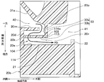
- FIG. 3 is a cross-sectional view of a blower of the vehicle air-conditioning apparatus according to the first embodiment, which is a view corresponding to a cross-sectional view taken along a line II in FIG. It is the schematic diagram seen from the axial direction one side of the air blower among the vehicle air conditioners in 1st Embodiment. It is an enlarged view of the A section in FIG. It is a figure which shows the inertia force which acts on copper powder in 1st Embodiment, gravity, and the relationship of the air flow direction.
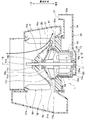
- FIG. 4 is a partially enlarged view of a blower according to a second embodiment, and is a view corresponding to FIG. 3.
- a blower 1 for an in-vehicle air conditioner according to the present embodiment will be described with reference to FIGS.
- the blower 1 is housed in an air conditioning case 2 and blows out an airflow toward a cooling heat exchanger 3 disposed in the air conditioning case 2.
- the air-conditioning case 2 of the present embodiment together with the cooling heat exchanger 3 and the heating heat exchanger, constitutes a well-known air-conditioning device for blowing conditioned air into the vehicle interior.
- the air-conditioning case 2 houses the blower 1 and collects the airflow blown out from the blower 1 and guides the airflow to the outlet 2a. And an introduction path 2c for leading to the exchanger 3. ⁇ ⁇ ⁇ If the radial dimension of the collecting passage 2b centered on the rotation center of the blower 1 is defined as a radial dimension r, the radial dimension r gradually increases from the rotation start portion 3a to the rotation end portion 3b.
- the air-conditioning case 2 is provided with a branch flow path 2d for guiding a part of the airflow flowing through the introduction path 2c to an introduction port 31 of a flange 20 described later.
- the blower 1 includes the electric motor 10, the flange 20, and the impeller 30.
- the electric motor 10 is an electric motor with a brush, and includes a rotating shaft 11, an armature 12, a yoke 13, a plurality of magnets 14, a commutator 15, brushes 16a and 16b, a cover 17, and a direct current including bearings 18a and 18b. It is a motor.
- the rotating shaft 11 is arranged so that its axis S extends in the vertical direction.
- the rotating shaft 11 is formed so as to extend along the axis S, and outputs a rotating force rotating about the axis S to the impeller 30.
- One side of the rotating shaft 11 in the axial direction projects upward from the through hole 17 e of the cover 17.
- the axial direction is a direction in which the axis S extends.
- the through-hole 17 e is formed in the protrusion 17 a of the cover 17.
- the armature 12 includes a rotor core 12a and a plurality of coils 12b.
- the rotor core 12 a is formed of a magnetic material such as iron and fixed to the rotating shaft 11.
- the plurality of coils 12b are respectively wound around the rotor core 12a. As a result, the armature 12 is supported by the rotating shaft 11.
- the yoke 13 is formed in a cylindrical shape having a bottom.
- the yoke 13 is formed of a magnetic material such as iron, and forms a passage through which a magnetic flux passes, as described later.
- the yoke 13, together with the cover 17, constitutes a motor case that houses the rotating shaft 11, the armature 12, and the plurality of magnets 14.
- the bottom of the yoke 13 of the present embodiment is provided with two inlets 13a through which cooling air flows into the motor interior 13b.
- the motor interior 13b is a space surrounded by the yoke 13 and the cover 17.
- the plurality of magnets 14 are arranged radially outward with respect to the armature 12 about the axis S. Each of the plurality of magnets 14 has a magnetic pole formed radially inward. Of the plurality of magnets 14, two magnets 14 arranged in a circumferential direction around the axis S have magnetic poles having different polarities. The plurality of magnets 14 are supported by the inner peripheral surface of the yoke 13.
- the commutator 15 is fixed to the rotating shaft 11.
- the commutator 15 is arranged on one side in the axial direction with respect to the armature 12.
- the commutator 15 includes a plurality of segments 15a.
- the plurality of segments 15a are arranged in a circumferential direction about the rotation shaft 11.
- the ends of the corresponding coil 12b among the plurality of coils 12b are connected to the plurality of segments 15a.
- the armature 12 is connected to the commutator 15.
- Each of the plurality of segments 15a of the present embodiment is mainly made of copper.
- the brushes 16a and 16b are in contact with the corresponding segment 15a among the plurality of segments 15a.
- the brushes 16a and 16b are fixed to the cover 17, respectively.
- the brushes 16a and 16b serve to supply electric power to the armature 12 through the commutator 15, as described later.
- the brushes 16a and 16b of the present embodiment are each mainly made of copper.
- the cover 17 is disposed on one side in the axial direction with respect to the yoke 13.
- the cover 17 is formed so as to cover the commutator 15 and the brushes 16a and 16b, respectively, from one side in the axial direction.
- the cover 17 includes a protrusion 17a, a cylindrical portion 17b, and an inclined portion 17c.
- the protrusion 17a is arranged radially inward with the axis S as the center.
- the protrusion 17a is formed so as to protrude to one side in the axial direction.
- the cylindrical portion 17b is disposed radially outward with respect to the projection 17a about the axis S, and formed in a cylindrical shape with the axis S as the center.
- the inclined portion 17c is arranged between the protrusion 17a and the cylindrical portion 17b.
- the inclined portion 17c is formed so as to gradually move toward the other side in the axial direction as it proceeds radially outward from the protrusion 17a.
- Two outlets 17d are provided radially inward of the inclined portion 17c to allow the cooling air passing through the inside of the yoke 13 to flow out to the air flow passage 40a.
- One outlet 17d of the two outlets 17d is disposed above the brush 16a, and the other outlet 17d of the two outlets 17d is disposed above the brush 16b.
- the cover 17 forms, together with the yoke 13, a motor case that houses the rotating shaft 11, the armature 12, the plurality of magnets 14, the commutator 15, the brushes 16a and 16b, and the bearings 18a and 18b.
- the bearing 18b rotatably supports one side in the axial direction with respect to the commutator 15 of the rotating shaft 11.
- the bearing 18b is fixed to the cover 17.
- the flange 20 supports the electric motor 10 from the outside in the radial direction and the other side in the axial direction, and is supported by the air conditioning case. Specifically, the flange 20 forms a maze-shaped air flow path 40 (that is, a first air flow path) that is arranged radially outward with respect to the electric motor 10 with respect to the cylindrical portion 20 a that houses the electric motor 10. And an outer diameter portion 20b to be formed. The details of the air flow path 40 will be described later.
- the outer diameter portion 20 b has an inlet 31 into which a part of the airflow blown out from the impeller 30 flows, and a cooling air flow path 34 that guides the airflow flowing through the inlet 31 to the two inlets 13 a of the yoke 13. Prepare.
- the impeller 30 is disposed on one side in the axial direction with respect to the flange 20 and the electric motor 10.
- the impeller 30 includes a main plate 31a, a ring portion 31b, and a plurality of blades 32.
- the main plate 31a is formed in an annular shape about the axis S.
- a through hole is provided at the center in the radial direction of the main plate 31a so as to penetrate in the axial direction.
- the rotating shaft 11 is fixed to the main plate 31a in a state where the rotating shaft 11 is press-fitted into the through hole of the main plate 31a.
- the main plate 31a is formed so as to head toward the other side in the axial direction as it goes radially outward from the center in the radial direction.
- an air flow path 40a (that is, a second air flow path) through which the cooling air passing through the inside 13b of the motor flows is formed. ing. Between the main plate 31a and the flange 20, there is formed an air passage 40 through which the cooling air from the air passage 40a flows.
- the cooling air is an air flow for cooling the armature 12 and the like.
- the plurality of blades 32 are respectively arranged on one side in the axial direction with respect to the main plate 31a.
- the plurality of blades 32 are arranged at intervals in the circumferential direction around the axis S.
- Each of the plurality of blades 32 is supported radially outward of the main plate 31a.
- the outer diameter portion 20b of the flange 20 is provided with an opposing surface 21 that is disposed on the other side in the axial direction with respect to the main plate 31a and opposes the main plate 31a.
- the facing surface 21 is formed in an annular shape about the axis S.
- the facing surface 21 is disposed radially outward with respect to the cylindrical portion 17b of the cover 17 (see FIG. 1).
- the outer diameter portion 20b is provided with a rib 20d extending from the radially inner side of the opposing surface 21 to one axial side along the cylindrical portion 17b of the cover 17.
- the outer diameter portion 20b is formed with a groove portion 20e that is disposed radially outward with respect to the rib 20d.
- the groove 20e is formed so as to open on one side in the axial direction and to be recessed from the facing surface 21 on the other side in the axial direction.
- the groove 20e is formed in an annular shape about the axis S.
- the groove 20e includes a bottom surface 20f, an inner peripheral surface 20g, and an outer peripheral surface 20h.
- the bottom surface 20f is a bottom portion arranged on the other side in the axial direction with respect to the groove portion 20e.
- the bottom surface 20f is formed in an annular shape about the axis S.
- the inner peripheral surface 20g is disposed above the bottom surface 20f.
- the inner peripheral surface 20g is arranged on the inner peripheral side with the axis S as a center with respect to the bottom surface 20f.
- the inner peripheral surface 20g is formed in the axial direction.
- the axial direction of the present embodiment coincides with the vertical direction in the vehicle interior. For this reason, the inner peripheral surface 20g is formed over the vertical direction. The inner peripheral side of the bottom surface 20f is connected to the inner peripheral surface 20g. Thus, the inner peripheral surface 20g and the bottom surface 20f constitute the corner 100.
- the outer peripheral surface 20h is a wall disposed above the bottom surface 20f.
- the outer peripheral surface 20h is arranged on the outer peripheral side around the axis S with respect to the bottom surface 20f.
- the outer peripheral surface 20h is formed in the axial direction. That is, the outer peripheral surface 20h is formed vertically.
- the outer peripheral side 111 of the bottom surface 20f is connected to the outer peripheral surface 20h.
- the outer peripheral surface 20h and the bottom surface 20f form the corner 101.
- the main plate 31a of the impeller 30 is provided with a rib 33 projecting to the other side in the axial direction.
- the rib 33 is arranged in the groove 20e.
- a gap 20k is formed between the rib 33 and the bottom surface 20f of the groove 20e.
- the ribs 33 and the groove portions 20e thus configured form a labyrinth structure that forms the air flow path 40 in a maze shape.
- the labyrinth structure plays a role in capturing wear powder (for example, copper powder) generated by friction between the commutator 15 and the brushes 16a and 16b.
- a rib 22 protruding from the facing surface 21 to one side in the axial direction is provided on the outer diameter portion 20b of the flange 20.
- the rib 22 is disposed on the outer peripheral side with respect to the axis S with respect to the groove 20e.
- the rib 22 is formed in an annular shape about the axis S.
- the rib 22 is located on the outermost side of the facing surface 21.
- An air outlet 41 of the air flow path 40 is formed between the rib 22 and the main plate 31 a of the impeller 30.
- a DC voltage from the battery is applied between two segments 15a (hereinafter, referred to as two contact segments 15a) that are in contact with the brushes 16a and 16b among the plurality of segments 15a through the brushes 16a and 16b.
- the current from the positive electrode of the battery flows to the negative electrode of the battery through the brush 16a, the coil 12b connecting between the two contact segments 15a, and the brush 16b.
- a magnetic flux is generated in the coil 12b by energization.
- a rotational force is generated between the coil 12b connecting the two contact segments 15a and the plurality of magnets 14.
- a rotational force is sequentially generated in the armature 12 based on the magnetic fields from the plurality of magnets 14. This sequentially generated torque is transmitted to the rotating shaft 11. Therefore, the rotating shaft 11 rotates around the axis S while being supported by the bearings 18a and 18b.
- the commutator 15 rotates together with the rotating shaft 11 in a state where the brushes 16a and 16b are in contact with the plurality of segments 15a. For this reason, the brushes 16a, 16b or the plurality of segments 15a are worn to generate wear powder.
- the abrasion powder is carried into the air passage 40a by the cooling air flowing inside the motor interior 13b. Therefore, as indicated by the bold arrow, the airflow flowing from the upper side into the groove 20e flows upward in the gap 20k while changing the airflow direction.
- the blower 1 includes the yoke 13 and the cover 17 constituting the motor case, the electric motor 10 with a brush, the flange 20, and the impeller 30.
- the brushed electric motor 10 includes a rotating shaft 11, a commutator 15, an armature 12, and brushes 16a and 16b.
- the rotating shaft 11 is disposed in the motor case, rotates about the axis S, and one side in the axial direction protrudes from the motor case.
- the commutator 15 is arranged in the motor case and rotates with the rotating shaft 11.
- the brushes 16a, 16b are arranged on the motor case and contact the commutator 15 to supply power to the armature 12 via the commutator 15.
- the armature 12 includes a plurality of coils 12b that are arranged in a motor case, supported by the rotating shaft 11, and connected to the commutator 15.
- the armature 12, together with the plurality of magnets 14, generates a rotating force for rotating the rotating shaft 11 based on the electric power from the brushes 16a, 16b.
- the flange 20 supports the electric motor 10 from the radial outside centering on the rotating shaft 11.
- the impeller 30 is disposed on one side in the axial direction with respect to the electric motor 10 and the flange 20, and rotates together with the rotating shaft 11 to generate an airflow.
- An air passage 40 is formed between the electric motor 10 and the flange 20 and between the impeller 30 and the cooling air passing through the motor case to flow radially outward.
- the flange 20 and the impeller 30 form a labyrinth structure in which the air flow path 40 is formed in a maze shape and traps abrasion powder generated by friction between the commutator 15 and the brushes 16a and 16b.
- the inner peripheral surface 20g and the bottom surface 20f form the corner 100.
- the outer peripheral surface 20h and the bottom surface 20f form a corner 101.
- the abrasion powder is captured in the air flow path 40 by retaining the abrasion powder at the corners 100 and 101.
- the rib 33 of the present embodiment as a shielding part, blocks a part of the airflow blown out from the impeller 30 from flowing into the air flow path 40. For this reason, the pressure loss of the airflow blown out from the blower 1 to the cooling heat exchanger 3 can be reduced.
- FIG. 10 shows the second embodiment in which the air flow path 40 is formed in a maze shape by two ribs formed on the flange 20 and a rib 33 formed on the impeller 30. It will be described with reference to FIG. 5, the same reference numerals as those in FIGS. 1 and 2 denote the same components, and a description thereof will be omitted.
- the rib 33 is formed so as to project from the main plate 31a of the impeller 30 to the other axial side.
- the rib 33 is formed in a circumferential direction about the axis S.
- the outer diameter portion 20b of the flange 20 includes an inner rib 121 and an outer diameter rib 120 instead of the groove 20e.
- the inner rib 121 is disposed radially inward of the rib 33 about the axis S.
- the inner rib 121 is formed so as to project from the bottom surface 20f to one side in the axial direction.
- the inner rib 121 is formed in a circumferential direction around the axis S.
- the inner rib 121 of the present embodiment forms an inner peripheral surface 20g.
- the inner peripheral surface 20g is disposed above the bottom surface 20f.
- the outer diameter rib 120 is disposed radially outward with respect to the rib 33 about the axis S.
- the outer diameter rib 120 is formed so as to project from the bottom surface 20f to one side in the axial direction.
- the outer diameter rib 120 is formed in a circumferential direction about the axis S.
- the outer diameter rib 120 of the present embodiment forms an outer peripheral surface 20h.
- the outer peripheral surface 20h is disposed above the bottom surface 20f.
- a gap 20k is formed between the rib 33 and the bottom surface 20f, as in the first embodiment.
- the outer peripheral surface 20h, the inner peripheral surface 20g, the bottom surface 20f, and the rib 33 form a labyrinth structure that forms the air flow path 40 in a maze shape. Is configured. Therefore, similarly to the first embodiment, it is possible to provide the air blower 1 capable of satisfactorily capturing wear powder generated by friction between the commutator 15 and the brushes 16a and 16b.
- the impeller 30 of the present embodiment is provided with a groove 20e instead of the rib 33.
- the groove 20e is formed so as to open on the other side in the axial direction and to be concave on one side in the axial direction.
- the groove 20e includes a ceiling surface 20n, an inner peripheral surface 20g, and an outer peripheral surface 20h.
- the ceiling surface 20n is arranged on one axial side with respect to the groove 20e.
- the ceiling surface 20n is formed in a circumferential direction about the axis S.
- the ceiling surface 20n is formed in a radial direction about the axis S.
- the inner peripheral surface 20g is disposed radially inward of the ceiling surface 20n about the axis S.
- the inner peripheral surface 20g is formed in a circumferential direction about the axis S.
- the inner peripheral surface 20g is formed in the axial direction.
- the outer peripheral surface 20h is arranged radially outward with respect to the ceiling surface 20n about the axis S.
- the outer peripheral surface 20h is formed in a circumferential direction around the axis S.
- the outer peripheral surface 20h is formed in the axial direction.
- a rib 33 is provided on the outer diameter portion 20b of the flange 20 of the present embodiment in place of the groove 20e.
- the rib 33 is disposed radially inward of the rib 20d about the axis S.
- the rib 33 is formed so as to protrude from the bottom surface 20f to one side in the axial direction.
- the rib 33 is formed in a circumferential direction about the axis S.
- a gap 20k is formed between the rib 33 and the ceiling surface 20n of the groove 20e.
- the inner peripheral surface 23b is formed on the inner peripheral side of the rib 33 around the axis S.
- the inner peripheral surface 23b is formed in a circumferential direction about the axis S.
- An outer peripheral surface 23a is formed radially outward of the rib 20d about the axis S.
- the outer peripheral surface 23a is formed in a circumferential direction around the axis S.
- the inner peripheral surface 23b, the outer peripheral surface 23a, and the bottom surface 20f of the present embodiment constitute a groove 25 that is recessed on the other side in the axial direction.
- the groove 25 is formed in a circumferential direction about the axis S.
- the groove 25 is opened on one side in the axial direction, and forms a part of the air flow path 40.
- the corner portion 100 is formed by connecting the outer peripheral side 110 side of the bottom surface 20f to the outer peripheral surface 23a.
- the outer peripheral surface 23a is arranged above the bottom surface 20f.
- the armature 12 sequentially generates a rotating force on the plurality of magnets 14 based on the DC voltage from the battery.
- This sequentially generated torque is transmitted to the impeller 30 through the rotating shaft 11. Therefore, the impeller 30 rotates about the axis S. Along with this, the impeller 30 sucks in the airflow from one side in the axial direction and blows it out radially outward.
- a part of the blown air flow passes from the inlet 31 through the cooling air flow path 34 and is led to the inlet 13 a of the yoke 13.
- the air flow guided to the inlet 13a flows into the yoke 13 as motor cooling air. Therefore, the airflow flowing in the yoke 13 cools the armature 12.
- the air flow passes around the armature 12 and then flows into the air flow passage 40 through the outlet 17d of the cover 17. Thereafter, when entering the groove 25, the airflow changes its flow direction and flows along the rib 33 to one side in the axial direction, and then enters the interval 20k.
- the air flow changes its flow direction to the other side in the axial direction as indicated by arrow kb.
- the air flow whose flow direction has been changed is blown out from the air outlet 41.
- the wear powder Since the direction of the air flow is different from the direction of the inertial force, the wear powder is peeled off from the air flow.
- the peeled wear powder moves to the bottom surface 20f side by gravity. After that, it moves to the corner 101 by the airflow in the groove 25 and the gravity.
- the blower 1 is provided between the electric motor 10 and the flange 20 and the impeller 30 through the air passage 40 that allows the cooling air that has passed through the motor case to flow radially outward. Are formed.
- the impeller 30 is provided with a groove 25 that is recessed on one side in the axial direction.
- a rib 33 projecting into the groove 20e is provided on the outer diameter portion 20b of the flange 20.
- the outer peripheral side 111 of the bottom surface 20f is connected to the outer peripheral surface 23a of the rib 33.
- the corner 101 is formed as a connection portion where the bottom surface 20f and the rib 33 are connected.
- the rib 33 and the groove portions 20e and 25 form a labyrinth structure that forms the air flow path 40 in a maze shape and captures abrasion powder generated by friction between the commutator 15 and the brushes 16a and 16b. .
- blower 1 in which the abrasion powder generated by friction between the commutator 15 and the brushes 16a and 16b is captured by the corner portion 101.
- a groove 20e is formed in the outer diameter portion 20b of the flange 20 of the present embodiment, and is recessed radially inward with the axis S as a center.
- the groove 20e is opened radially outward with respect to the axis S.
- the groove 20e forms a maze-shaped air flow path 40 together with the rib 33.
- the groove 20e is formed by the facing surface 21, the rib 20d, and the rib 20m.
- the rib 20m is formed so as to protrude radially outward around the axis S from one axial end of the rib 20d.
- the rib 20m is formed in a circumferential direction around the axis S.
- the main plate 31a of the impeller 30 of the present embodiment is provided with a rib 33 formed in an L-shaped cross section and protruding in the groove 20e.
- the rib 33 includes an upper rib 33a protruding from the main plate 31a of the impeller 30 to the other axial side, and a lower rib 33b protruding radially inward from the other axial end of the upper rib 33a. I have.
- the upper rib 33a and the lower rib 33b are connected.
- the radially inner side of the upper rib 33a forms a wall 114a.
- the upper side of the lower rib 33b forms the bottom surface 113.
- the wall portion 114a is disposed above the bottom surface 113.
- the corner portion 103 is formed by connecting the wall portion 114a and the bottom surface 113.
- an interval 20k is provided between the lower rib 33b and the rib 20d.
- An interval 20p is provided between the rib 2m and the upper rib 33a.
- An interval 20r is provided between the lower rib 33b and the facing surface 21.
- the intervals 20p, 20k, and 20r in the present embodiment each constitute a part of the air flow path 40.
- the corners 104 are formed by connecting the ribs 20d to the radially inner side 114 side of the facing surface 21.
- the rib 20d is disposed above the opposing surface 21.
- the groove 20e and the rib 33 configured as described above configure the air flow path 40 in a maze shape, and form a labyrinth structure that captures wear powder generated by friction between the commutator 15 and the brushes 16a and 16b.
- the rotating force generated in the armature 12 based on the DC voltage from the battery is transmitted to the impeller 30 through the rotating shaft 11. For this reason, the impeller 30 rotates. Along with this, the impeller 30 sucks in the airflow from one side in the axial direction and blows it out radially outward.
- a part of the blown air flow passes through the cooling air flow path 34 from the inlet 31 and is guided to the two inlets 13 a of the yoke 13.
- the air flow guided to these two inlets 13a flows into the yoke 13 as cooling air. Therefore, the cooling air flowing in the yoke 13 cools the armature 12 and the like.
- the cooling air passes through the periphery of the armature 12 and the like, and then flows into the air passage 40 through the two outlets 17d of the cover 17. Thereafter, as shown by the arrow Kb, when the cooling air enters the groove 20e through the interval 20p, it flows radially inward along the lower rib 33b. Then, the cooling air changes its flow direction at intervals of 20k and flows radially outward at intervals of 20r. Thereafter, the air is blown out from the outlet 41.
- the abrasion powder stays on the corner 104 side of the air flow path 40 and is captured. As described above, the abrasion powder separated from the air flow stays in the groove 20e and is captured.
- the blower 1 is provided between the electric motor 10 and the flange 20 and the impeller 30 through the air passage 40 that allows the cooling air that has passed through the motor case to flow radially outward.
- the outer diameter portion 20b of the flange 20 is provided with a groove 20e that is recessed radially inward.
- the impeller 30 is provided with a rib 33 projecting into the groove 20e.
- the rib 33 and the groove 20e form a labyrinth structure in which the air flow path 40 is formed in a maze shape, and the wear powder generated by friction between the commutator 15 and the brushes 16a and 16b is captured by the corners 103 and 104.
- blower device 1 capable of satisfactorily capturing wear powder generated by friction between the commutator 15 and the brushes 16a and 16b.
- the blower 1 of the present embodiment has ribs 42a, 42b, and 42c added in the air passage 40a of the blower 1 of the first embodiment.
- the rib 42a is formed so as to project from the main plate 31a to the other side in the axial direction.
- the rib 42a is arranged radially outward around the axis S with respect to the outlet 17d.
- the rib 42a is formed in an annular shape about the axis S.
- An interval 203 that forms a part of the air flow path 40 is formed between the rib 42a and the inclined portion 17c of the cover 17.
- a corner 211 is formed by connecting the rib 42a and the main plate 31a.
- the rib 42b is formed so as to project from the main plate 31a to the other side in the axial direction.
- the rib 42b is disposed radially outward with respect to the rib 42a about the axis S.
- the rib 42b is formed in an annular shape about the axis S.
- An interval 202 forming a part of the air flow path 40 is formed between the rib 42b and the inclined portion 17c of the cover 17.
- a corner 212 is formed by connecting the rib 42b and the main plate 31a.
- the rib 42c is formed so as to project from the inclined portion 17c of the cover 17 to one side in the axial direction.
- the rib 42c is disposed between the ribs 42a and 42b.
- the rib 42c is formed in an annular shape about the axis S.
- An interval 202 forming a part of the air flow path 40 is formed between the rib 42c and the main plate 31a.
- a corner 213 is formed by connecting the rib 42c and the inclined portion 17c of the cover 17.
- the ribs 42a, 42b, and 42c form a labyrinth structure that forms the air flow path 40 in a maze shape.
- the peeled-off wear powder stays at the corners 213 and the like and is captured. As described above, the wear powder separated from the air flow stays in the air flow path 40 and is captured.
- the blower 1 is provided between the electric motor 10 and the flange 20 and the impeller 30 through the air passage 40 that allows the cooling air that has passed through the motor case to flow radially outward. Are formed.
- the rib 33 and the groove 20e form a first labyrinth structure that forms the air flow path 40 in a maze shape and captures wear powder.
- the main plate 31a of the impeller 30 and the inclined portion 17c of the cover 17 form the air flow path 40 in a maze shape, and constitute a second labyrinth structure for capturing wear powder. .
- blower device 1 that more appropriately captures wear powder generated by friction between the commutator 15 and the brushes 16a and 16b.
- FIG. 9 illustrates the sixth embodiment in which the flange and the air-conditioning case 2 are integrated. It will be described with reference to FIG. 9, the same reference numerals as those in FIG. 1 denote the same components, and a description thereof will be omitted.
- the flange of the present embodiment since the flange and the air conditioning case 2 are integrated by resin molding, the flange becomes a part of the air conditioning case 2.
- the flange of the present embodiment is referred to as a flange 20A.
- the air passage 40 is formed in a maze shape by the air conditioning case 2 (that is, the flange 20A) and the impeller 30 to form a labyrinth structure that captures abrasion powder. Become.
- the rib 33 in FIG. 1 functions as a shielding part and blocks a part of the airflow blown out from the impeller 30 from flowing into the air flow path 40. For this reason, the pressure loss of the airflow blown out from the blower 1 to the cooling heat exchanger 3 can be reduced.
- the air blower includes an electric motor including a motor case, and a rotation shaft arranged in the motor case, rotating around an axis, and having one axial side protruding from the motor case.
- the blower is connected to one side of the rotating shaft of the electric motor in the axial direction, and is a blade that rotates together with the rotating shaft (11) and blows out an airflow sucked from one side in the axial direction to the outside in the radial direction around the axis.
- a vehicle (30) is provided.
- the air blower has an air flow path (40) between the flange and the impeller that allows the cooling air that has passed through the motor case to flow radially outward.
- the blower is provided with a shield (33) that suppresses the airflow blown from the impeller from flowing into the air flow path.
- the shielding part is configured by an impeller.
- the shielding unit may be configured by the electric motor (10) or the air conditioning case (2).
- blower is applied to the air conditioner for the vehicle. Instead, the blower is applied to various air conditioners other than the air conditioner for the vehicle. Is also good.
- the blower when referring to the shape of components and the like, positional relationship, and the like, unless otherwise specified and in principle limited to a specific shape, positional relationship, etc., the shape, It is not limited to a positional relationship or the like.
- the sensor when the acquisition of the external environment information of the vehicle (for example, the humidity outside the vehicle) from the sensor is described, the sensor is abolished and the external environment information is obtained from the server or the cloud outside the vehicle. It is also possible to receive. Alternatively, it is also possible to eliminate the sensor, obtain related information related to the external environment information from a server or a cloud outside the vehicle, and estimate the external environment information from the obtained related information.
- the blower includes an electric motor with a brush, a flange supporting the electric motor, and an impeller. Is provided.
- An electric motor with a brush is arranged so as to extend along an axis in the motor case, a rotating shaft that rotates around the axis, and projects on one side in the axial direction from the motor case, and a motor case. And a commutator supported on the rotating shaft.
- An electric motor with a brush is arranged in a motor case and connected to a commutator, and a brush arranged in the motor case and in contact with the commutator to supply power to the armature through the commutator.
- the impeller is arranged on one side in the axial direction with respect to the electric motor and the flange, and the impeller is arranged on one side in the axial direction with respect to the electric motor and the flange. Occurs.
- Cooling air for cooling the armature flows in the motor case, and an air flow path is formed between the flange and the impeller for flowing the cooling air passing through the motor case.
- the flange and the impeller form a labyrinth structure that forms an air flow path in a maze shape and captures wear powder generated by friction between the commutator and the brush.
- At least one of the flange and the impeller is formed in the vertical direction on the bottom and the upper side with respect to the bottom, and is connected to the bottom, so that the air flow path together with the bottom is formed in a maze shape. And a wall to be formed.
- the bottom and wall are connected to form a corner.
- the abrasion powder is captured in the air flow path.
- the abrasion powder can be better captured in the air flow path.
- a motor case is provided between the electric motor and the fan.
- a second air passage that guides the passed cooling air to the first air passage is formed.
- the electric motor and the fan form a second labyrinth structure that forms the second air flow path in a maze shape and captures abrasion powder.
- the abrasion powder can be better captured in the air flow path.
- the air conditioner includes an electric motor with a brush, an impeller, and an air conditioning case that forms a first air flow path that guides an air flow generated from the impeller to the heat exchanger.
- An electric motor with a brush is arranged so as to extend along an axis in the motor case, a rotating shaft that rotates around the axis, and projects on one side in the axial direction from the motor case, and a motor case. And a commutator supported on the rotating shaft.
- An electric motor with a brush is arranged in a motor case and connected to a commutator, and a brush arranged in the motor case and in contact with the commutator to supply power to the armature through the commutator. , And the armature generates a rotating force for rotating the rotating shaft based on the electric power.
- the impeller is arranged on one side in the axial direction with respect to the electric motor, and rotates with the rotating shaft to generate an air flow.
- the air-conditioning case forms a first air passage that guides the air flow generated from the impeller to the heat exchanger. Cooling air for cooling the armature flows in the motor case, and a second air flow path for flowing the cooling air passing through the motor case is formed between the air conditioning case and the impeller.
- the air conditioning case and the fan form a labyrinth structure in which the second air flow path is formed in a maze shape, and wear powder generated by friction between the commutator and the brush is captured in the second air flow path.
Landscapes
- Engineering & Computer Science (AREA)
- Mechanical Engineering (AREA)
- General Engineering & Computer Science (AREA)
- Physics & Mathematics (AREA)
- Thermal Sciences (AREA)
- Structures Of Non-Positive Displacement Pumps (AREA)
- Air-Conditioning For Vehicles (AREA)
- Motor Or Generator Cooling System (AREA)
Abstract
La présente invention concerne un ventilateur comprenant un moteur électrique (10) doté d'un balai, le moteur électrique comprenant : un boîtier (13, 17) ; un arbre de rotation (11) disposé de façon à s'étendre le long d'une ligne axiale (S) à l'intérieur du boîtier, un côté dans la direction de ligne axiale de l'arbre de rotation faisant saillie à partir du boîtier ; un commutateur (15) ; un induit (12) ; et un balai (16a, 16b), l'induit générant une force de rotation qui met en rotation l'arbre de rotation sur la base de la puissance électrique. Le ventilateur comprend : une bride (20) qui supporte le moteur électrique ; et une roue (30) disposée sur un côté dans la direction de la ligne axiale par rapport au moteur électrique et à la bride, la roue (30) se mettant en rotation conjointement avec l'arbre de rotation et générant un courant d'air. De l'air de refroidissement qui refroidit l'induit s'écoule à l'intérieur du boîtier, un canal d'écoulement d'air (40) qui fait circuler l'air de refroidissement qui a traversé le boîtier étant formé entre la bride et la roue, la bride et la roue formant le canal d'écoulement d'air en forme de labyrinthe, et constituant une structure de labyrinthe qui piège la poudre d'abrasion générée par frottement entre le commutateur et le balai.
Applications Claiming Priority (2)
| Application Number | Priority Date | Filing Date | Title |
|---|---|---|---|
| JP2018169039A JP2020040500A (ja) | 2018-09-10 | 2018-09-10 | 送風装置、空調装置 |
| JP2018-169039 | 2018-09-10 |
Publications (1)
| Publication Number | Publication Date |
|---|---|
| WO2020054448A1 true WO2020054448A1 (fr) | 2020-03-19 |
Family
ID=69778277
Family Applications (1)
| Application Number | Title | Priority Date | Filing Date |
|---|---|---|---|
| PCT/JP2019/033936 Ceased WO2020054448A1 (fr) | 2018-09-10 | 2019-08-29 | Ventilateur et climatiseur |
Country Status (2)
| Country | Link |
|---|---|
| JP (1) | JP2020040500A (fr) |
| WO (1) | WO2020054448A1 (fr) |
Families Citing this family (1)
| Publication number | Priority date | Publication date | Assignee | Title |
|---|---|---|---|---|
| JP7515104B2 (ja) | 2020-07-07 | 2024-07-12 | パナソニックIpマネジメント株式会社 | ファンモータ |
Citations (5)
| Publication number | Priority date | Publication date | Assignee | Title |
|---|---|---|---|---|
| JPH079064U (ja) * | 1993-07-05 | 1995-02-07 | 株式会社安川電機 | ファンモータの防塵構造 |
| JP2008280928A (ja) * | 2007-05-10 | 2008-11-20 | Denso Corp | 送風装置 |
| JP2013051788A (ja) * | 2011-08-30 | 2013-03-14 | Asmo Co Ltd | 回転電機 |
| JP2015017564A (ja) * | 2013-07-11 | 2015-01-29 | 株式会社デンソー | 送風機 |
| JP2018133943A (ja) * | 2017-02-16 | 2018-08-23 | 株式会社デンソー | ブラシ付き電動モータ |
-
2018
- 2018-09-10 JP JP2018169039A patent/JP2020040500A/ja active Pending
-
2019
- 2019-08-29 WO PCT/JP2019/033936 patent/WO2020054448A1/fr not_active Ceased
Patent Citations (5)
| Publication number | Priority date | Publication date | Assignee | Title |
|---|---|---|---|---|
| JPH079064U (ja) * | 1993-07-05 | 1995-02-07 | 株式会社安川電機 | ファンモータの防塵構造 |
| JP2008280928A (ja) * | 2007-05-10 | 2008-11-20 | Denso Corp | 送風装置 |
| JP2013051788A (ja) * | 2011-08-30 | 2013-03-14 | Asmo Co Ltd | 回転電機 |
| JP2015017564A (ja) * | 2013-07-11 | 2015-01-29 | 株式会社デンソー | 送風機 |
| JP2018133943A (ja) * | 2017-02-16 | 2018-08-23 | 株式会社デンソー | ブラシ付き電動モータ |
Also Published As
| Publication number | Publication date |
|---|---|
| JP2020040500A (ja) | 2020-03-19 |
Similar Documents
| Publication | Publication Date | Title |
|---|---|---|
| JP6599791B2 (ja) | 電動送風機および電気掃除機 | |
| US8049380B2 (en) | Electric motor | |
| US20180180058A1 (en) | Fan device and vacuum cleaner including the same | |
| JP6718365B2 (ja) | 電動送風機および電気掃除機 | |
| CN209743188U (zh) | 送风装置以及吸尘器 | |
| JP2014136997A (ja) | 汚れ固着防止機能を有するファンモータおよびファンモータを有する装置 | |
| JP2021085399A (ja) | 送風装置及び掃除機 | |
| EP3086448B1 (fr) | Dispositif de mise à la terre pour machine électrique et procédés d'assemblage de celui-ci | |
| US9685843B2 (en) | Grounding device for electric machine and methods of assembling the same | |
| CN108730209A (zh) | 电动鼓风机及搭载了该电动鼓风机的电动吸尘器 | |
| WO2020255807A1 (fr) | Moteur électrique et souffleuse électrique | |
| JP2007224779A (ja) | ファンモータ | |
| JP2018133943A (ja) | ブラシ付き電動モータ | |
| WO2020054448A1 (fr) | Ventilateur et climatiseur | |
| CN210120448U (zh) | 马达、送风装置以及吸尘器 | |
| JP2013051788A (ja) | 回転電機 | |
| JP6635994B2 (ja) | 送風装置 | |
| CN211009178U (zh) | 送风装置和吹风机 | |
| US2753473A (en) | Self-cleaning dynamoelectric machine | |
| JP2016205336A (ja) | 遠心送風機および掃除機 | |
| JP2022062289A (ja) | 電動機及び電動送風機 | |
| JP2010041756A (ja) | 電動機 | |
| JP6859074B2 (ja) | 電動機および電気掃除機 | |
| CN110680229A (zh) | 电动风机和搭载其的电动吸尘器 | |
| JP6711330B2 (ja) | 電動モータ |
Legal Events
| Date | Code | Title | Description |
|---|---|---|---|
| 121 | Ep: the epo has been informed by wipo that ep was designated in this application |
Ref document number: 19860786 Country of ref document: EP Kind code of ref document: A1 |
|
| NENP | Non-entry into the national phase |
Ref country code: DE |
|
| 122 | Ep: pct application non-entry in european phase |
Ref document number: 19860786 Country of ref document: EP Kind code of ref document: A1 |