WO2020054470A1 - 磁気冷凍装置 - Google Patents
磁気冷凍装置 Download PDFInfo
- Publication number
- WO2020054470A1 WO2020054470A1 PCT/JP2019/034285 JP2019034285W WO2020054470A1 WO 2020054470 A1 WO2020054470 A1 WO 2020054470A1 JP 2019034285 W JP2019034285 W JP 2019034285W WO 2020054470 A1 WO2020054470 A1 WO 2020054470A1
- Authority
- WO
- WIPO (PCT)
- Prior art keywords
- flow path
- heat medium
- branch
- temperature
- magnetic
- Prior art date
- Legal status (The legal status is an assumption and is not a legal conclusion. Google has not performed a legal analysis and makes no representation as to the accuracy of the status listed.)
- Ceased
Links
Images


Classifications
-
- F—MECHANICAL ENGINEERING; LIGHTING; HEATING; WEAPONS; BLASTING
- F25—REFRIGERATION OR COOLING; COMBINED HEATING AND REFRIGERATION SYSTEMS; HEAT PUMP SYSTEMS; MANUFACTURE OR STORAGE OF ICE; LIQUEFACTION SOLIDIFICATION OF GASES
- F25B—REFRIGERATION MACHINES, PLANTS OR SYSTEMS; COMBINED HEATING AND REFRIGERATION SYSTEMS; HEAT PUMP SYSTEMS
- F25B21/00—Machines, plants or systems, using electric or magnetic effects
-
- F—MECHANICAL ENGINEERING; LIGHTING; HEATING; WEAPONS; BLASTING
- F25—REFRIGERATION OR COOLING; COMBINED HEATING AND REFRIGERATION SYSTEMS; HEAT PUMP SYSTEMS; MANUFACTURE OR STORAGE OF ICE; LIQUEFACTION SOLIDIFICATION OF GASES
- F25B—REFRIGERATION MACHINES, PLANTS OR SYSTEMS; COMBINED HEATING AND REFRIGERATION SYSTEMS; HEAT PUMP SYSTEMS
- F25B2321/00—Details of machines, plants or systems, using electric or magnetic effects
- F25B2321/002—Details of machines, plants or systems, using electric or magnetic effects by using magneto-caloric effects
- F25B2321/0021—Details of machines, plants or systems, using electric or magnetic effects by using magneto-caloric effects with a static fixed magnet
-
- F—MECHANICAL ENGINEERING; LIGHTING; HEATING; WEAPONS; BLASTING
- F25—REFRIGERATION OR COOLING; COMBINED HEATING AND REFRIGERATION SYSTEMS; HEAT PUMP SYSTEMS; MANUFACTURE OR STORAGE OF ICE; LIQUEFACTION SOLIDIFICATION OF GASES
- F25B—REFRIGERATION MACHINES, PLANTS OR SYSTEMS; COMBINED HEATING AND REFRIGERATION SYSTEMS; HEAT PUMP SYSTEMS
- F25B2321/00—Details of machines, plants or systems, using electric or magnetic effects
- F25B2321/002—Details of machines, plants or systems, using electric or magnetic effects by using magneto-caloric effects
- F25B2321/0023—Details of machines, plants or systems, using electric or magnetic effects by using magneto-caloric effects with modulation, influencing or enhancing an existing magnetic field
-
- Y—GENERAL TAGGING OF NEW TECHNOLOGICAL DEVELOPMENTS; GENERAL TAGGING OF CROSS-SECTIONAL TECHNOLOGIES SPANNING OVER SEVERAL SECTIONS OF THE IPC; TECHNICAL SUBJECTS COVERED BY FORMER USPC CROSS-REFERENCE ART COLLECTIONS [XRACs] AND DIGESTS
- Y02—TECHNOLOGIES OR APPLICATIONS FOR MITIGATION OR ADAPTATION AGAINST CLIMATE CHANGE
- Y02B—CLIMATE CHANGE MITIGATION TECHNOLOGIES RELATED TO BUILDINGS, e.g. HOUSING, HOUSE APPLIANCES OR RELATED END-USER APPLICATIONS
- Y02B30/00—Energy efficient heating, ventilation or air conditioning [HVAC]
Definitions
- the present disclosure relates to a magnetic refrigerator.
- the magnetic refrigeration apparatus of Patent Document 1 includes a magnetic work material, a magnetic field generator (magnetic field modulation unit) that applies a magnetic field to the magnetic work material, a pump (fluid transport mechanism), and a heat exchanger.
- the pumped liquid (heat medium) flows around the magnetic working material.
- a magnetic field is applied to the magnetic substance by the magnetic field modulator, the magnetic substance generates heat.
- the heat medium heated by the magnetic field generating material flows through the heat exchanger and exchanges heat with air.
- An object of the present disclosure is to provide a magnetic refrigeration apparatus that can adjust the pressure of a main flow path.
- a first aspect of the present disclosure is directed to a main flow path (12) through which a heat medium flows, a magnetic work substance (23), and a flow path connected to the main flow path (12) and arranged with the magnetic work substance (23).
- a magnetic refrigeration unit (20) having a case (22) for forming channels (21, 25, 26), a magnetic field modulation unit (24) for applying a magnetic field variation to the magnetic work material (23), and the main flow path
- a second operation for connecting the heating medium in the main flow path in a first direction and a second operation for transferring the heating medium in a second direction opposite to the first direction.
- a fluid transfer mechanism (30) that alternately performs an operation, wherein the main flow path (12) includes at least one branch flow branching between the magnetic refrigeration unit (20) and the fluid transfer mechanism (30). And a control valve (60, 63, 64, 153, 163) including a channel (50, 150, 160) and connected to the branch channel (50, 150, 160). It is a gas refrigeration apparatus.
- the pressure in the main flow path (12) can be adjusted by adjusting the opening of the control valve (60, 63, 64, 153, 163).
- the main flow path (12) is provided between one end of the flow path (21, 25, 26) of the magnetic refrigeration unit (20) and the fluid transfer mechanism (30).
- a first flow path (13) formed therebetween, and formed between the other end of the flow path (21, 25, 26) of the magnetic refrigeration unit (20) and the fluid transfer mechanism (30).
- a second flow path (14), the branch flow path (50) being an intermediate flow path (51) connected between the first flow path (13) and the second flow path (14).
- a magnetic refrigeration apparatus characterized by including:
- the intermediate flow path (51) is connected between the first flow path (13) and the second flow path (14).
- the heat medium in the first flow path (13) is diverted to the intermediate flow path (51).
- the heat medium in the second flow path (14) is diverted to the intermediate flow path (51). Therefore, in both the first operation and the second operation, the flow rate of the heat medium flowing through the magnetic refrigerator (20) can be adjusted.
- a third aspect is the magnetic refrigeration apparatus according to the second aspect, wherein the intermediate flow path (51) communicates the first flow path (13) with the second flow path (14). It is.
- the heat medium in the first flow path (13) is diverted to the intermediate flow path (51). Since the intermediate flow path (51) communicates with the second flow path (14) on the suction side, the heat medium in the first flow path (13) quickly flows into the intermediate flow path (51).
- the heat medium in the second flow path (14) is diverted to the intermediate flow path (51). Since the intermediate flow path (51) communicates with the first flow path (13) on the suction side, the heat medium in the first flow path (13) quickly flows into the intermediate flow path (51). In this way, by making the branch flow path (50) communicate with the first flow path (13) and the second flow path (14), it is possible to improve the responsiveness of the flow rate adjustment in the branch flow path (50).
- a fourth aspect is the magnetic refrigeration apparatus according to the third aspect, wherein an inner volume of the intermediate flow path (51) is larger than a discharge amount of one operation of the fluid transport mechanism (30). Device.
- the internal volume of the intermediate flow path (51) is larger than the discharge amount of the fluid transfer mechanism (30) in the first operation and the second operation, for example, the intermediate flow from the first flow path (13)
- the heat medium flowing into the path (51) can be prevented from flowing into the second flow path (14).
- the intermediate channel (51) is provided with a cylinder (55) for communicating the first channel (13) and the second channel (14).
- a partition member (56) that is provided in the cylinder (55) so as to be able to advance and retreat, and that divides the inside of the cylinder (55) into two internal flow paths (57, 58). It is a magnetic refrigerator.
- the first flow path (13) and the second flow path (14) are partitioned by the partition member (56) of the cylinder (55). Therefore, it is possible to suppress the occurrence of heat loss due to the mixing of the heat medium in the first flow path (13) and the heat medium in the second flow path (14).
- the cylinder (55) moves in and out of the cylinder (55) due to a pressure difference between the first flow path (13) and the second flow path (14).
- the maximum volume of one internal flow path (57, 58) of the cylinder (55) is larger than the discharge amount of one operation of the fluid transfer mechanism (30). Is also large.
- the entire amount of the heat medium discharged from the fluid transfer mechanism (30) can flow into the cylinder (55). Therefore, it is possible to ensure the maximum adjustment range of the flow rate of the heat medium to be diverted to the branch flow path (50).
- the branch flow path (50) includes a branch pipe (52, 53) having one end connected to the main flow path (12), and the branch pipe (52, 53). And a reservoir (61, 62) connected to the other end of the magnetic refrigeration apparatus.
- the heat medium diverted from the main flow path (12) flows into the reservoirs (61, 62). Thereby, the flow rate of the heat medium in the magnetic refrigeration unit (20) can be adjusted.
- the reservoirs (61, 62) communicate with the suction side of the fluid transport mechanism (30), the heat medium in the reservoirs (61, 62) returns to the main flow path (12) again.
- the volume of the reservoir (61, 62) is larger than twice the discharge amount of one operation of the fluid transport mechanism (30). It is a magnetic refrigerator.
- the heat medium diverted from the main flow path (12) in the first operation and the second operation can be sufficiently stored in the reservoirs (61, 62).
- the low-temperature side connected to the first flow path (13) and through which the heat medium cooled in the magnetic refrigeration unit (20) is transported is provided.
- a magnetic refrigeration apparatus comprising: a control valve (60) connected to a position (51) closer to the second flow path (14) than to the first flow path (13).
- the opening of the control valve (60) of the intermediate flow path (51) by adjusting the opening of the control valve (60) of the intermediate flow path (51), the flow resistance of the intermediate flow path (51) changes, and the intermediate flow path (12) The flow rate of the heat medium diverted to (51) is adjusted.
- the control valve (60) is connected to a position closer to the high temperature side second flow path (14) than to the low temperature side first flow path (13). Therefore, it is possible to suppress the heat of the control valve (60) from moving to the heat medium in the first flow path (13).
- a tenth aspect is the low-temperature side heat exchange according to any one of the second to sixth aspects, wherein the heat medium is connected to the first flow path (13) and the heat medium cooled in the case (22) is transported.
- a high-temperature side heat exchanger (42) connected to the second flow path (14) and carrying the heat medium heated in the case (22);
- One end of 51) is connected between the fluid transfer mechanism (30) and the low-temperature side heat exchanger (41) in the first flow path (13), and the other end of the intermediate flow path (51)
- a magnetic refrigeration apparatus which is connected between the fluid transfer mechanism (30) and the high-temperature side heat exchanger (42) in the second flow path (14).
- the heat medium discharged from the fluid transport mechanism (30) is diverted to the intermediate flow path (51) before passing through the low-temperature heat exchanger (41) or the high-temperature heat exchanger (42). I do.
- the main flow path (12) is provided with one end of the flow path (21, 25, 26) of the magnetic refrigeration unit (20) and the fluid transfer mechanism (30).
- the magnetic refrigeration apparatus is connected to a second branch flow path (160), and a control valve (153, 163) is connected to each of the two branch flow paths (150, 160).
- control valves (153, 163) are connected to the two branch flow paths (150, 160), respectively. For this reason, the opening degree of the control valve (153, 163) of the branch flow path (150, 160) corresponding to the discharge side of the fluid transport mechanism (30) can be reduced or closed, and the branch flow path (150, 160) on the discharge side can be closed. Dividing of the heat medium can be suppressed.
- each of the two branch flow paths (150, 160) includes a branch pipe (151, 161) having one end connected to the main flow path (12), and the branch pipe (151, 161). And an accumulator (152, 162) connected to the other end of the magnetic refrigeration apparatus.
- accumulators (152, 162) are connected to the respective branch flow paths (150, 160). For this reason, the pressure drop of the heat medium on the suction side of the fluid transport mechanism (30) can be suppressed.
- a thirteenth aspect is the magnetic refrigeration apparatus according to the eleventh or twelfth aspect, further comprising a control device (70) for closing a control valve (153, 163) on the discharge side of the fluid transport mechanism (30). is there.
- control device (70) closes the control valve (153, 163) on the discharge side of the fluid transfer mechanism (30), so that the heat medium on the discharge side of the fluid transfer mechanism (30) passes through the branch channel ( 150, 160).
- control device (70) is configured to control the discharge-side control valve of the fluid transport mechanism (30) in synchronization with the operation timing of the fluid transport mechanism (30).
- (153, 163) is a magnetic refrigeration apparatus characterized by closing.
- control valves (153, 163) on the discharge side of the fluid transport mechanism (30) are closed in synchronization with the first operation and the second operation of the fluid transport mechanism (30). This can prevent the heat medium on the discharge side of the fluid transport mechanism (30) from being diverted to the branch flow paths (150, 160).
- control device (70) synchronizes with the timing of the operation of the fluid transport mechanism (30) to control the suction side of the fluid transport mechanism (30).
- a magnetic refrigeration apparatus characterized by opening control valves (153, 163).
- control valves (153, 163) on the suction side of the fluid transport mechanism (30) are opened in synchronization with the first operation and the second operation of the fluid transport mechanism (30). Thereby, the pressure drop of the heat medium on the suction side of the fluid transport mechanism (30) can be suppressed.
- a pressure corresponding to a pressure between the first branch flow path (150) and the fluid transfer mechanism (30) is detected in the main flow path (12).
- a first pressure sensor (154) and a second pressure sensor (164) for detecting a pressure corresponding to a pressure between the second branch flow path (160) and the fluid transport mechanism (30).
- the control device (70) switches the control valve (153, 163) of the branch flow path (150, 160) corresponding to the pressure sensor (154, 164).
- a magnetic refrigeration apparatus characterized by being closed.
- the control valves (53, 63) are closed. Therefore, in each of the two operations, the control valve (153, 163) on the discharge side can be automatically closed.
- the control device (70) may control the branch flow path (150, 160) corresponding to the pressure sensor (154, 164). ), Wherein the control valves (153, 163) are opened.
- the control valves (153, 163) are closed. Therefore, in each of the two operations, the control valve (153, 163) on the suction side can be automatically opened.
- An eighteenth aspect is the magnetic refrigeration apparatus according to the seventeenth aspect, wherein the first value is larger than the second value.
- a temperature corresponding to the temperature between the first branch flow path (150) and the fluid transport mechanism (30) is set in the main flow path (12).
- the controller (70) corrects the second value based on the temperature detected by the temperature sensors (155, 165).
- the second value used to determine whether to close the control valve (153, 163) on the suction side is corrected based on the temperature of the heat medium on the suction side. This is because the pressure at which cavitation occurs (corresponding to the saturated vapor pressure here) changes depending on the temperature.
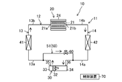
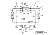
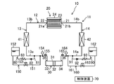
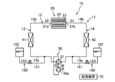
- FIG. 1 is a piping diagram schematically illustrating the configuration of the magnetic refrigerator according to the first embodiment.
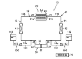
- FIG. 2 is a piping diagram schematically illustrating a configuration of the magnetic refrigeration apparatus according to Embodiment 1, and illustrates a flow of a heat medium in a heating operation.
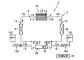
- FIG. 3 is a piping diagram schematically illustrating the configuration of the magnetic refrigeration apparatus according to Embodiment 1, and illustrates the flow of the heat medium in the cooling operation.
- FIG. 4 is a diagram corresponding to FIG. 1 according to the second embodiment.
- FIG. 5 is a diagram corresponding to FIG. 1 according to the third embodiment.
- FIG. 6 is a diagram corresponding to FIG. 1 according to the first modification.
- FIG. 7 is a diagram corresponding to FIG. 1 according to the second modification.
- FIG. 8 is a diagram corresponding to FIG. 1 according to the third modification.
- FIG. 9 is a diagram corresponding to FIG. 1 according to the fourth modification.
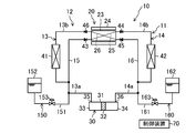
- FIG. 10 is a piping diagram schematically illustrating a configuration of a magnetic refrigeration apparatus according to Embodiment 4.
- FIG. 11 is a piping diagram schematically illustrating a configuration of a magnetic refrigeration apparatus according to Embodiment 4, and illustrates a flow of a heat medium in a heating operation.
- FIG. 12 is a piping diagram schematically illustrating a configuration of a magnetic refrigeration apparatus according to Embodiment 4, and illustrates a flow of a heat medium in a cooling operation.
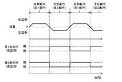
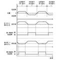
- FIG. 13 is a timing chart regarding the flow rate, the first control valve, and the second control valve in the control operation according to the fourth embodiment.
- FIG. 10 is a piping diagram schematically illustrating a configuration of a magnetic refrigeration apparatus according to Embodiment 4.
- FIG. 11 is a piping diagram schematically illustrating a configuration of a
- FIG. 14 is a diagram corresponding to FIG. 10 according to the fifth embodiment.
- FIG. 15 is a timing chart regarding the flow rate, the pressure, the first control valve, and the second control valve in the control operation according to the fifth embodiment.
- FIG. 16 is a timing chart regarding the flow rate, the pressure, the first control valve, and the second control valve in the control operation according to the sixth embodiment.
- FIG. 17 is a diagram corresponding to FIG. 10 according to the seventh embodiment.
- FIG. 18 is a diagram corresponding to FIG. 10 according to the eighth embodiment.
- FIG. 19 is a diagram corresponding to FIG. 10 according to the fifth modification.
- FIG. 20 is a diagram corresponding to FIG. 10 according to the sixth modification.
- FIG. 21 is a diagram corresponding to FIG. 10 according to the seventh modification.
- FIG. 22 is a diagram corresponding to FIG. 10 according to another embodiment.
- Embodiment 1 The magnetic refrigeration apparatus (10) of the present embodiment adjusts the temperature of the heat medium using the magnetocaloric effect.
- the magnetic refrigerator (10) is applied to, for example, an air conditioner.
- the magnetic refrigerator (10) includes a heat medium circuit (11) filled with a heat medium.
- Each component of the heat medium circuit (11) is connected to each other via a pipe.
- the heat medium circuit (11) includes a closed loop main flow path (12) and a branch flow path (50) branched from the main flow path (12).
- the magnetic refrigeration apparatus (10) includes a magnetic refrigeration unit (20) (magnetic refrigeration unit), a pump (30), a low-temperature heat exchanger (41), and a high-temperature heat exchanger (42).
- the pump (30), the low-temperature side heat exchanger (41), the temperature control flow path (21) of the magnetic refrigeration unit (20), and the high-temperature side heat exchanger (42) are arranged in this order. Connected.
- the main flow path (12) includes a low-temperature flow path (13) and a high-temperature flow path (14).
- the low temperature side flow path (13) is formed between one end of the temperature control flow path (21) of the magnetic refrigeration unit (20) and the first port (35) of the pump (30).
- the low temperature side channel (13) forms a first channel.
- One end of the temperature control flow path (21) forms a first connection port (21a).
- the high temperature side flow path (14) is formed between the other end of the temperature control flow path (21) of the magnetic refrigeration unit (20) and the second port (36) of the pump (30).
- the high temperature side channel (14) forms a second channel.
- the other end of the temperature control flow path (21) forms a second connection port (21b).
- the low temperature side channel (13) may be the second channel
- the high temperature side channel (14) may be the first channel.
- the low temperature side flow path (13) includes a first pump side pipe (13a) formed between the low temperature side heat exchanger (41) and the pump (30), a low temperature side heat exchanger (41) and a magnetic refrigeration unit. And a first magnetic side pipe (13b) formed between the unit and the unit (20).
- the high temperature side flow path (14) includes a second pump side pipe (14a) formed between the high temperature side heat exchanger (42) and the pump (30), and the high temperature side heat exchanger (42) and the magnetic refrigeration. And a second magnetic side pipe (14b) formed between the first magnetic section and the second section (20).
- the pump (30) of the present embodiment constitutes a fluid transfer mechanism that reciprocates the heat medium in the main flow path (12). That is, the pump (30) performs the first operation of transporting the heat medium in the main flow path (12) in the first direction (the direction indicated by the solid arrow in FIG. 2), and the heat medium in the main flow path (12) in the first direction. And the second operation of transporting in the opposite second direction (the direction indicated by the solid arrow in FIG. 3) is alternately repeated.
- the pump (30) of the present embodiment is constituted by a reciprocating piston pump.
- the pump (30) includes a pump case (31) and a piston (32) arranged to be able to advance and retreat inside the pump case (31).
- the piston (32) partitions the inside of the pump case (31) into a first chamber (33) and a second chamber (34).
- a first port (35) communicating with the first chamber (33) and a second port (36) communicating with the second chamber (34) are formed in the pump case (31).
- the first port (35) is connected to the low temperature side channel (13), and the second port (36) is connected to the high temperature side channel (14).
- the piston (32) is driven by a drive mechanism not shown.
- the drive mechanism has a rod connected to the piston (32), a crank connected to the rod, and an electric motor driving the crank.
- the motor rotates the crank, the rod moves forward and backward.
- the reciprocating motion of the piston (32) is performed in the pump case (31), and the first operation and the second operation are alternately repeated.
- the piston (32) moves toward the first port (35), and the volume of the first chamber (33) decreases and the volume of the second chamber (34) increases.
- the heat medium in the first chamber (33) is discharged to the low temperature side channel (13) through the first port (35).
- the heat medium in the high temperature side flow path (14) is sucked into the second chamber (34) through the second port (36).
- the piston (32) moves toward the second port (36), and the volume of the second chamber (34) decreases and the volume of the first chamber (33) increases.
- the heat medium in the second chamber (34) is discharged to the high temperature side channel (14) through the second port (36).
- the heat medium in the low temperature side channel (13) is sucked into the first chamber (33) through the first port (35).
- the low-temperature side heat exchanger (41) exchanges heat between the heat medium cooled by the magnetic refrigeration unit (20) and a predetermined object to be cooled (for example, a secondary refrigerant or air).
- the high-temperature side heat exchanger (42) exchanges heat between the heat medium heated by the magnetic refrigeration unit (20) and a predetermined heating target (for example, a secondary refrigerant or air).
- the magnetic refrigeration unit (20) includes a bed (22), a magnetic work material (23) arranged in a temperature control flow path (21) in the bed (22), and a magnetic field fluctuation applied to the magnetic work material (23). And a magnetic field modulating section (24) to be provided.
- the bed (22) is a hollow case or column, and is filled with a magnetic work substance (23).
- the magnetic working material (23) has a property of generating heat when a magnetic field is applied or when the applied magnetic field is strong, and absorbing heat when the magnetic field is removed or the applied magnetic field is weakened.
- the magnetic field modulator (24) adjusts the strength of the magnetic field applied to the magnetic work material (23).
- the magnetic field modulation unit (24) is formed of, for example, an electromagnet capable of modulating a magnetic field.
- the magnetic field modulating unit (24) applies a magnetic field to the magnetic work material (23) or increases the applied magnetic field, and removes or applies the magnetic field applied to the magnetic work material (23). And a second modulation operation for weakening the applied magnetic field.
- the branch channel (50) is a channel for adjusting the pressure of the main channel (12).
- the branch flow path (50) is a flow path for adjusting the flow rate of the heat medium flowing through the temperature control flow path (21) of the magnetic refrigeration unit (20). That is, the branch flow path (50) is configured such that the heat medium in the main flow path (12) flows in, and adjusts the flow rate in the temperature control flow path (21) in accordance with the flow rate of the divided heat medium.
- the branch flow path (50) of the present embodiment constitutes an intermediate flow path (51) connected between the low-temperature flow path (13) and the high-temperature flow path (14).
- the intermediate flow path (51) forms a communication path that connects the low-temperature flow path (13) and the high-temperature flow path (14).
- One end of the intermediate flow path (51) is connected to the first pump side pipe (13a).
- the other end of the intermediate flow path (51) is connected to the second pump side pipe (14a).
- a control valve (60) is connected to the branch flow path (50).
- the control valve (60) constitutes a flow path resistance adjusting unit that adjusts the flow path resistance so as to adjust the flow rate of the heat medium diverted to the branch flow path (50).
- the control valve (60) is formed of, for example, a motor-operated valve, and is configured such that its opening can be adjusted.
- the control valve (60) is connected to the high temperature side flow path (14) in the branch flow path (50). That is, the control valve (60) is connected to a position closer to the high-temperature side flow path (14) than the low-temperature side flow path (13) in the intermediate flow path (51). By disposing the control valve (60) near the high-temperature side flow path (14), it is possible to suppress the heat generated from the control valve (60) from moving to the low-temperature heat medium in the low-temperature side flow path (13).
- Va be the entire internal volume of the intermediate flow path (51), which is a communication path.
- the capacity (discharge amount) of the heat medium discharged from the pump (30) in one first operation is Vd1.
- the capacity (discharge amount) of the heat medium discharged from the pump (30) in one second operation is Vd2.
- the discharge amount Vd1 of the first operation of the pump (30) is equal to the discharge flow rate Vd2 of the second operation of the pump (30).
- the entire internal volume Va of the intermediate flow path (51) is set larger than Vd1 and Vd2.
- the magnetic refrigerator (10) includes a control device (70) for controlling the control valve (60).
- the control device (70) is configured using a microcomputer and a memory device (specifically, a semiconductor memory) that stores software for operating the microcomputer.
- the control device (70) adjusts the opening of the control valve (60) based on a predetermined control signal.
- the magnetic refrigerator (10) alternately repeats the heating operation shown in FIG. 2 and the cooling operation shown in FIG.
- the cycle of switching between the heating operation and the cooling operation is set to about 1 second.
- the pump (30) performs the first operation, and the magnetic field modulator (24) performs the first modulation operation. That is, in the heating operation, the heat medium is discharged from the first port (35) of the pump (30). At the same time, a magnetic field is applied to the magnetic work substance (23), or the applied magnetic field is strengthened.
- the heat medium in the low temperature side flow path (13) becomes the temperature control flow path of the magnetic refrigeration unit (20). It flows into the first connection port (21a) of (21).
- the heat medium flowing through the temperature control flow path (21) is heated by the magnetic work substance (23).
- the heat medium heated in the temperature control flow path (21) flows out of the second connection port (21b) to the high temperature side flow path (14), and flows through the high temperature side heat exchanger (42).
- a predetermined heating target (secondary refrigerant, air, or the like) is heated by a high-temperature heat medium.
- the heat medium in the high temperature side flow path (14) is drawn into the second chamber (34) from the second port (36) of the pump (30).
- the pump (30) performs the second operation and the magnetic field modulator (24) performs the second modulation operation. That is, in the heating operation, the magnetic field of the magnetic working material (23) is removed or the applied magnetic field is weakened at the same time when the heat medium is discharged from the second port (36) of the pump (30).
- the heat medium in the high-temperature side flow path (14) becomes the temperature control flow path of the magnetic refrigeration unit (20). It flows into the second connection port (21b) of (21).
- the magnetic work material (23) takes away the heat of the surroundings. Therefore, the heat medium flowing through the temperature control flow path (21) is cooled by the magnetic work material (23).
- the heat medium cooled in the temperature control flow path (21) flows out of the first connection port (21a) to the low-temperature side flow path (13), and flows through the low-temperature side heat exchanger (41).
- a predetermined cooling target (secondary refrigerant, air, or the like) is cooled by a low-temperature heat medium.
- the heat medium in the low temperature side flow path (13) is sucked into the first chamber (33) from the first port (35) of the pump (30).
- the flow rate of the temperature control flow path (21) is appropriately adjusted.
- the temperature of the heat medium heated by the magnetic work substance (23) can be appropriately adjusted.
- the control valve (60) when the control valve (60) is opened at a predetermined opening, a part of the heat medium in the high-temperature side flow path (14) is diverted to the branch flow path (50), as indicated by a broken arrow in FIG. I do. Therefore, the flow rate Qc of the temperature control flow path (21) decreases.
- the flow rate of the temperature control flow path (21) is appropriately adjusted.
- the temperature of the heat medium cooled by the magnetic work substance (23) can be appropriately adjusted.
- the pressure of the main flow path (12) can be adjusted by sending a part of the heat medium in the main flow path (12) to the branch flow path (50).
- the pressure of the main flow path (12) can be adjusted by flowing the heat medium in the main flow path (12) into the branch flow path (50).
- a discharge flow rate of a fluid transfer mechanism such as a pump is used. May be adjusted.
- a fluid transfer mechanism such as a pump
- the flow rate of the heat medium in the temperature control flow path (21) can be adjusted by flowing the heat medium in the main flow path (12) into the branch flow path (50). Therefore, even with a fixed-capacity type fluid transfer mechanism such as a reciprocating pump (30), the flow rate of the temperature control flow path (21) can be adjusted.
- the flow rate of the heat medium flowing through the branch flow path (50) can be finely adjusted, and the temperature control flow path (21) The flow rate of the heat medium flowing through the can be finely adjusted.
- the branch flow path (50) is an intermediate flow path (51) connected between the low-temperature flow path (13) and the high-temperature flow path (14). For this reason, the heat medium can be divided by both the heating operation and the cooling operation by the single branch flow path (50).
- the intermediate flow path (51) is a communication path that connects the low-temperature flow path (13) and the high-temperature flow path (14). Therefore, the suction pressure of the pump (30) can be applied to the intermediate flow path (51), and the heat medium can be quickly diverted to the branch flow path (50). Specifically, for example, in the heating operation, the suction pressure on the second port (36) side of the pump (30) acts on the high temperature side end of the branch flow path (50). Therefore, a part of the heat medium discharged from the first port (35) quickly flows into the branch flow path (50). Further, for example, in the cooling operation, the suction pressure on the first port (35) side of the pump (30) acts on the low temperature side end of the branch flow path (50).
- the internal volume of the branch flow path (50), which is a communication passage, is larger than the discharge amount of the pump (30) in the first operation and the second operation. For this reason, in the first operation, it is possible to prevent the heat medium in the low-temperature side channel (13) from flowing out to the high-temperature side channel (14) via the branch channel (50). In the second operation, it is possible to prevent the heat medium in the high temperature side flow path (14) from flowing out to the low temperature side flow path (13) via the branch flow path (50). As a result, it is possible to prevent the heat medium on the high temperature side and the heat medium on the low temperature side from being mixed, and to avoid heat loss due to the mixing of these heat mediums.
- the control valve (60) is arranged closer to the high temperature side flow path (14) in the branch flow path (50). Therefore, it is possible to suppress the heat generated from the control valve (60) from moving to the heat medium in the low-temperature side flow path (13). As a result, it is possible to suppress an increase in the temperature of the heat medium in the low-temperature side flow path (13) due to the heat generated by the control valve (60).
- branch flow path (50) which is the intermediate flow path (51) is between the pump (30) and the low-temperature heat exchanger (41) in the low-temperature flow path (13) (that is, the first pump-side pipe). (13a)), and the other end is connected between the pump (30) and the high-temperature side heat exchanger (42) in the high-temperature side flow path (14) (that is, the second pump-side pipe (14a)).
- the heat medium after passing through the low-temperature side heat exchanger (41) does not flow to the branch flow path (50). Therefore, it is possible to prevent so-called cold heat of the heat medium in the low-temperature side heat exchanger (41) from being discarded to the branch flow path (50).
- the heat medium that has passed through the high-temperature side heat exchanger (42) does not flow to the branch flow path (50). Therefore, it is possible to avoid that the heat of the heat medium in the high-temperature side heat exchanger (42) is discarded toward the branch flow path (50).
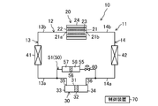
- the branch flow path (50) of the second embodiment is an intermediate flow path connected between the low-temperature flow path (13) and the high-temperature flow path (14), as in the first embodiment. (51).
- the intermediate flow path (51) of the second embodiment does not strictly communicate the low-temperature flow path (13) and the high-temperature flow path (14).
- a cylindrical cylinder (55) is connected to the branch channel (50) of the second embodiment.
- the cylinder (55) communicates the low-temperature side channel (13) and the high-temperature side channel (14) by the space inside.
- a columnar partition member (56) is provided inside the cylinder (55) so as to be able to advance and retreat.
- the partition member (56) fits inside the cylinder (55) and partitions the inside of the cylinder (55) into two parts. Specifically, the inside of the cylinder (55) is partitioned by a partition member (56) into a first internal channel (57) communicating with the low-temperature channel (13) and a second internal channel (57) communicating with the high-temperature channel (14). It is partitioned into two internal flow paths (58).
- the cylinder (55) reciprocates inside the cylinder (55) due to the pressure difference between the first internal flow path (57) and the second internal flow path (58). As a result, the volumes of the first internal channel (57) and the second internal channel (58) change.
- the maximum volume Vmax1 of the first internal flow path (57) is larger than the discharge amount Vd1 of the pump (30) in one first operation.
- the maximum volume Vmax2 of the second internal flow path (58) is larger than the discharge amount Vd2 of the pump (30) in one second operation.
- a control valve (60) is connected to the branch flow path (50) in series with the cylinder (55).
- the control valve (60) is connected between the cylinder (55) and the high temperature side flow path (14). Thereby, it is possible to suppress the heat of the control valve (60) from moving to the heat medium in the low-temperature side flow path (13).
- the opening of the control valve (60) by adjusting the opening of the control valve (60), the flow rate of the heat medium diverted to the branch flow path (50) can be adjusted, and thus the flow rate of the heat medium in the temperature control flow path (21). Is adjusted.
- the heat medium in the low-temperature side flow path (13) is divided into the branch flow path (50) and flows into the first internal flow path (57) of the cylinder (55).
- the suction pressure on the second port (36) side of the pump (30) acts on the second internal flow path (58). Therefore, the partition member (56) moves toward the high-temperature side flow path (14), and the volume of the first internal flow path (57) increases.
- the heat medium in the low temperature side channel (13) accumulates in the first internal channel (57).
- the maximum volume Vmax1 of the first internal flow path (57) is larger than the discharge amount Vd1 of the pump (30) in the first operation, the heat medium of the low temperature side flow path (13) is transferred to the first internal flow path. (57). In this way, the flow of the heat medium in the low temperature side flow path (13) to the branch flow path (50) can be adjusted to the flow rate of the heat medium in the temperature control flow path (21).
- the heat medium in the high-temperature side flow path (14) is divided into the branch flow path (50) and flows into the second internal flow path (58) of the cylinder (55).
- the suction pressure on the first port (35) side of the pump (30) acts on the first internal flow path (57). Therefore, the partition member (56) moves toward the low-temperature side flow path (13), and the volume of the second internal flow path (58) increases. Accordingly, the heat medium in the high-temperature side flow path (14) accumulates in the second internal flow path (58).
- the heat medium of the high temperature side flow path (14) is transferred to the second internal flow path. (58).
- the flow rate of the heat medium in the temperature control flow path (21) can be adjusted.
- the partition member (56) Since the first internal flow path (57) and the second internal flow path (58) are partitioned by the partition member (56), the heat medium of the low-temperature flow path (13) and the heat medium of the high-temperature flow path (14) are separated. Mixing with the medium can be reliably avoided. Therefore, it is possible to avoid causing heat loss due to such mixing of the heat medium.
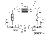
- one branch channel (52, 53) is connected to each of the low-temperature channel (13) and the high-temperature channel (14).
- one end of a first branch pipe (52), which is a branch flow path is connected to the low temperature side flow path (13).
- a first reservoir (61) is connected to the other end of the first branch pipe (52).
- One end of a second branch pipe (53), which is a branch flow path, is connected to the high temperature side flow path (14).
- a second reservoir (62) is connected to the other end of the second branch pipe (53).
- the first reservoir (61) and the second reservoir (62) are constituted by containers capable of storing a heat medium.
- the first reservoir (61) and the second reservoir (62) are provided with a pressure relief valve (not shown).
- the actual volume Vr1 inside the first reservoir (61) is equal to the actual volume Vr2 inside the second reservoir (62).
- These actual volumes Vr1 and Vr2 are larger than twice the discharge amounts Vd1 and Vd2 of the pump (30) in the first operation and the second operation.
- the first branch pipe (52) is connected to a first control valve (63), which is a flow path resistance adjuster.
- the second branch pipe (53) is connected to a second control valve (64) that is a flow path resistance adjusting unit.
- the first control valve (63) and the second control valve (64) are configured by, for example, motor-operated valves, and are configured such that their opening degrees can be adjusted.
- the control device (70) adjusts the opening of the first control valve (63) during the heating operation, and adjusts the opening of the second control valve (64) during the cooling operation.
- the heat medium in the low temperature side flow path (13) is diverted to the first branch pipe (52).
- the heat medium in the first branch pipe (52) accumulates in the first reservoir (61).
- the actual volume Vr1 of the first reservoir (61) is larger than twice the discharge amount of the pump (30) in the first operation or the second operation, a sufficient amount of the heat medium is filled in the first reservoir (61). Can be stored.
- the heat medium stored in the second reservoir (62) returns to the high-temperature side flow path (14) and is sucked into the second port (36) of the pump (30). Since the actual volume Vr2 of the second reservoir (62) is larger than twice the discharge amount Vd2 of the pump (30) in the first operation or the second operation, the heat medium of the second reservoir (62) becomes empty. Can be avoided.
- the second control valve (64) when the second control valve (64) is opened at a predetermined opening in the cooling operation, the heat medium in the high-temperature side flow path (14) is diverted to the second branch pipe (53).
- the heat medium in the second branch pipe (53) accumulates in the second reservoir (62).
- the actual volume Vr2 of the second reservoir (62) is larger than twice the discharge amount Vd2 of the pump (30) in the second operation, it is necessary to sufficiently store the heat medium in the second reservoir (62). Can be.
- the flow rate of the heat medium of the temperature control flow path (21) can be adjusted.
- the heat medium stored in the first reservoir (61) returns to the low temperature side flow path (13) and is sucked into the first port (35) of the pump (30). Since the actual volume Vr1 of the first reservoir (61) is larger than twice the discharge amount of the pump (30) in the first operation or the second operation, the heat medium of the first reservoir (61) becomes empty. Can be avoided.
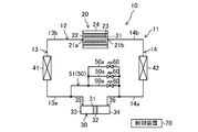
- Modification Example 1 shown in FIG. 6 differs from Embodiment 1 in the configurations of the branch flow path (50) (the intermediate flow path (51)) and the flow path resistance adjusting unit (control valve).
- the branch flow path (50) of the first modification includes a plurality of parallel pipes (50a, 50a, 50a) connected in parallel with each other. In this example, three parallel pipes (50a) are provided in the branch flow path (50).
- One control valve (60) is connected to each parallel pipe (50a).
- Each control valve (60) of this example is constituted by, for example, an electromagnetic on-off valve, and opens and closes the corresponding parallel pipe (50a).
- Each control valve (60) constitutes a flow path resistance adjusting unit that adjusts the flow path resistance of the branch flow path (50).
- the flow rate of the heat medium in the temperature control flow path (21) is adjusted according to the open / close state of each control valve (60). For example, when all three control valves (60) are closed, the flow rate of the heat medium in the temperature control flow path (21) becomes equal to the discharge rate of the pump (30). When one of the three control valves (60) is opened and the other is closed, the flow rate of the heat medium in the branch flow path (50) increases, and the flow rate in the temperature control flow path (21) decreases. I do. When two of the three control valves (60) are opened and the rest are closed, the flow rate of the heat medium in the branch flow path (50) further increases, and the heat medium in the temperature control flow path (21) increases. Is further reduced. Thus, in the modified example, as the number of control valves (60) to be opened increases, the flow rate of the heat medium in the branch flow path (50) decreases.
- the plurality of parallel pipes (50a) and the plurality of control valves (60) according to the first modification may be employed in the branch flow path (50) of the second or third embodiment.
- the inflow end of the heating channel (25) is connected to the first pump side pipe (13a) via the low temperature side bypass channel (15).
- a first check valve (43) is connected to the low temperature side bypass flow path (15). The first check valve (43) allows only the flow of the heat medium toward the heating flow path (25) in the low-temperature side bypass flow path (15), and prohibits the reverse flow.
- the outflow end of the heating channel (25) is connected to the high-temperature side heat exchanger (42) via the second magnetic side pipe (14b).
- a second check valve (44) is connected to the second magnetic side pipe (14b). The second check valve (44) allows only the flow of the heat medium toward the high-temperature side heat exchanger (42) in the second magnetic pipe (14b), and prohibits the reverse flow.
- the inflow end of the cooling channel (26) is connected to the second pump-side pipe (14a) via the high-temperature-side bypass channel (16).
- a third check valve (45) is connected to the high temperature side bypass flow path (16). The third check valve (45) allows only the flow of the heat medium toward the cooling flow path (26) in the high temperature side bypass flow path (16), and prohibits the reverse flow.
- the outflow end of the cooling channel (26) is connected to the low temperature side heat exchanger (41) via the first magnetic side pipe (13b).
- a fourth check valve (46) is connected to the first magnetic side pipe (13b). The fourth check valve (46) allows only the flow of the heat medium toward the low-temperature side heat exchanger (41) in the first magnetic side pipe (13b), and prohibits the reverse flow.
- the heat medium conveyed by the pump (30) during the first operation flows through the heating flow path (25) after passing through the low-temperature bypass flow path (15).
- the heat medium is heated by the magnetic work substance (23).
- the heated heat medium is conveyed to the high-temperature side heat exchanger (42) and used for heating the object to be heated.
- the heat medium in the high temperature side flow path (14) is sucked into the second port (36) of the pump (30).
- the flow rate of the heat medium flowing through the heating flow path (25) can be adjusted by diverting the heat medium into the branch flow path (50).
- the heat medium conveyed by the pump (30) during the second operation flows through the cooling flow path (26) after passing through the high-temperature side bypass flow path (16).
- the heat medium is cooled by the magnetic work substance (23).
- the cooled heat medium is conveyed to the low-temperature side heat exchanger (41) and is used for cooling the object to be cooled.
- the heat medium in the low temperature side channel (13) is sucked into the first port (35) of the pump (30).
- the flow rate of the heat medium flowing through the cooling flow path (26) can be adjusted by diverting the heat medium into the branch flow path (50).
- the heat medium circuit (11) according to the second modification may be employed in the second and third embodiments.
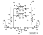
- ⁇ Modification 3> In the third modification shown in FIG. 8, a plurality (two in this example) of magnetic refrigeration units (20) are connected in parallel in the same heat medium circuit (11) as the second modification. Therefore, in the heating operation, the heat medium in the low-temperature side flow path (13) is heated in the heating flow paths (25) of the two magnetic refrigeration units (20), and then transported to the high-temperature side heat exchanger (42). Is done. In the cooling operation, the heat medium in the high-temperature side flow path (14) is cooled in the cooling flow paths (26) of the two magnetic refrigeration units (20), respectively, and then transferred to the low-temperature side heat exchanger (41). .
- the flow rate of the heat medium flowing through each heating flow path (25) can be adjusted by adjusting the flow rate of the heat medium flowing to the branch flow path (50) in the heating operation.
- the flow rate of the heat medium flowing through each cooling flow path (26) can be adjusted.
- the heat medium circuit (11) according to the third modification may be adopted in the second and third embodiments.
- Modification 4 shown in FIG. 9 is the same as Modification 2 except that a plurality (two in this example) of magnetic refrigeration units (20) are connected in series. Accordingly, in the heating operation, the heat medium in the low-temperature side flow path (13) is sequentially heated in each heating flow path (25) of each magnetic refrigeration unit (20), and then transported to the high-temperature side heat exchanger (42). Is done. In the cooling operation, the heat medium in the high-temperature side flow path (14) is sequentially cooled in each cooling flow path (26) of each magnetic refrigeration unit (20), and then transferred to the low-temperature side heat exchanger (41). .
- the flow rate of the heat medium flowing through each heating flow path (25) can be adjusted by adjusting the flow rate of the heat medium diverted to the branch flow path (50) in the heating operation.
- the flow rate of the heat medium flowing through each cooling flow path (26) can be adjusted.
- the heat medium circuit (11) according to the fourth modification may be adopted in the second and third embodiments.
- Embodiment 4 The magnetic refrigeration apparatus (10) of the fourth embodiment adjusts the temperature of the heat medium using the magnetocaloric effect.
- the magnetic refrigerator (10) is applied to, for example, an air conditioner.
- the magnetic refrigerator (10) includes a heating medium circuit (11) filled with a heating medium.
- Each component of the heat medium circuit (11) is connected to each other via a pipe.
- the heat medium circuit (11) includes a closed loop main flow path (12) and two branch flow paths (50, 60) branched from the main flow path (12).
- the magnetic refrigeration apparatus (10) includes a magnetic refrigeration unit (20) (magnetic refrigeration unit), a pump (30), a low-temperature heat exchanger (41), and a high-temperature heat exchanger (42).
- the pump (30), the low-temperature side heat exchanger (41), the temperature control flow path (21) of the magnetic refrigeration unit (20), and the high-temperature side heat exchanger (42) are arranged in this order. Connected.
- the main flow path (12) includes a low-temperature flow path (13) and a high-temperature flow path (14).
- the low temperature side flow path (13) is formed between one end of the temperature control flow path (21) of the magnetic refrigeration unit (20) and the first port (35) of the pump (30).
- the low temperature side channel (13) constitutes a first channel.
- One end of the temperature control flow path (21) forms a first connection port (21a).
- the high temperature side flow path (14) is formed between the other end of the temperature control flow path (21) of the magnetic refrigeration unit (20) and the second port (36) of the pump (30).
- the high temperature side channel (14) forms a second channel.
- the other end of the temperature control flow path (21) forms a second connection port (21b).
- the low temperature side channel (13) may be the second channel
- the high temperature side channel (14) may be the first channel.
- the low temperature side flow path (13) includes a first pump side pipe (13a) formed between the low temperature side heat exchanger (41) and the pump (30), a low temperature side heat exchanger (41) and a magnetic refrigeration system. And a first magnetic side pipe (13b) formed between the unit and the unit (20).
- the high temperature side flow path (14) includes a second pump side pipe (14a) formed between the high temperature side heat exchanger (42) and the pump (30), and the high temperature side heat exchanger (42) and the magnetic refrigeration. And a second magnetic side pipe (14b) formed between the first magnetic section and the second section (20).
- the pump (30) of the present embodiment constitutes a fluid transfer mechanism that reciprocates the heat medium in the main flow path (12). That is, the pump (30) performs the first operation of transporting the heat medium in the main flow path (12) in the first direction (the direction indicated by the solid arrow in FIG. 11) and the heat medium in the main flow path (12) in the first direction. And the second operation of transporting in the opposite second direction (the direction indicated by the solid arrow in FIG. 12) is alternately repeated.
- the pump (30) of the present embodiment is constituted by a reciprocating piston pump.
- the pump (30) includes a pump case (31) and a piston (32) arranged to be able to advance and retreat inside the pump case (31).
- the piston (32) partitions the inside of the pump case (31) into a first chamber (33) and a second chamber (34).
- a first port (35) communicating with the first chamber (33) and a second port (36) communicating with the second chamber (34) are formed in the pump case (31).
- the first port (35) is connected to the low temperature side channel (13), and the second port (36) is connected to the high temperature side channel (14).
- the piston (32) is driven by a drive mechanism not shown.
- the drive mechanism has a rod connected to the piston (32), a crank connected to the rod, and an electric motor driving the crank.
- the motor rotates the crank, the rod moves forward and backward.
- the reciprocating motion of the piston (32) is performed in the pump case (31), and the first operation and the second operation are alternately repeated.
- the piston (32) moves toward the first port (35), and the volume of the first chamber (33) decreases and the volume of the second chamber (34) increases.
- the heat medium in the first chamber (33) is discharged to the low temperature side channel (13) through the first port (35).
- the heat medium in the high temperature side flow path (14) is sucked into the second chamber (34) through the second port (36).
- the piston (32) moves toward the second port (36), and the volume of the second chamber (34) decreases and the volume of the first chamber (33) increases.
- the heat medium in the second chamber (34) is discharged to the high temperature side channel (14) through the second port (36).
- the heat medium in the low temperature side channel (13) is sucked into the first chamber (33) through the first port (35).
- the low-temperature side heat exchanger (41) exchanges heat between the heat medium cooled by the magnetic refrigeration unit (20) and a predetermined object to be cooled (for example, a secondary refrigerant or air).
- the high-temperature side heat exchanger (42) exchanges heat between the heat medium heated by the magnetic refrigeration unit (20) and a predetermined heating target (for example, a secondary refrigerant or air).
- the magnetic refrigeration unit (20) includes a bed (22), a magnetic work material (23) arranged in a temperature control flow path (21) in the bed (22), and a magnetic field fluctuation applied to the magnetic work material (23). And a magnetic field modulating section (24) to be provided.
- the bed (22) is a hollow case or column, and is filled with a magnetic work substance (23).
- the magnetic working material (23) has a property of generating heat when a magnetic field is applied or when the applied magnetic field is strong, and absorbing heat when the magnetic field is removed or the applied magnetic field is weakened.
- the magnetic field modulator (24) adjusts the strength of the magnetic field applied to the magnetic work material (23).
- the magnetic field modulation unit (24) is formed of, for example, an electromagnet capable of modulating a magnetic field.
- the magnetic field modulating unit (24) applies a magnetic field to the magnetic work material (23) or increases the applied magnetic field, and removes or applies the magnetic field applied to the magnetic work material (23). And a second modulation operation for weakening the applied magnetic field.
- the first branch flow path (150) and the second branch flow path (160) are connected to the heat medium circuit (11).
- the first branch channel (150) is connected to the low temperature channel (13).
- the second branch channel (160) is connected to the high temperature side channel (14).
- the first branch channel (150) includes a third branch pipe (151) and a first accumulator (152).
- One end of the third branch pipe (151) is connected to the first pump side pipe (13a) of the low temperature side flow path (13).
- the first accumulator (152) is connected to the other end of the third branch pipe (151).
- the first accumulator (152) forms a container into which the heat medium can flow.
- a third control valve (153) is connected to the third branch pipe (151).
- the third control valve (153) is configured by, for example, an electromagnetic on-off valve. That is, the third control valve (153) is switched between a closed state in which the first branch flow path (150) is closed and an open state in which the first branch flow path (150) is opened.
- the second branch channel (160) includes a fourth branch pipe (161) and a second accumulator (162).
- One end of the fourth branch pipe (161) is connected to the second pump side pipe (14a) of the high temperature side flow path (14).
- the second accumulator (162) is connected to the other end of the fourth branch pipe (161).
- the second accumulator (162) forms a container into which the heat medium can flow.
- a fourth control valve (163) is connected to the fourth branch pipe (161).
- the fourth control valve (163) is composed of, for example, an electromagnetic on-off valve. That is, the fourth control valve (163) is switched between a closed state in which the second branch flow path (160) is closed and an open state in which the second branch flow path (160) is opened.
- the magnetic refrigerator (10) includes a control device (70) for controlling the third control valve (153) and the fourth control valve (163).
- the control device (70) is configured using a microcomputer and a memory device (specifically, a semiconductor memory) that stores software for operating the microcomputer.
- the control device (70) of the present embodiment controls the third control valve (153) and the fourth control valve (163) in synchronization with the timing of the first operation and the second operation. Specifically, when the first operation is performed, the control device (70) closes the third control valve (153) on the discharge side of the pump (30). In addition, when the first operation is performed, the control device (70) opens the fourth control valve (163) on the suction side of the pump (30). On the other hand, when the second operation is performed, the control device (70) closes the fourth control valve (163) on the discharge side of the pump (30). In addition, when the second operation is performed, the control device (70) opens the third control valve (153) on the suction side of the pump (30) (see FIG. 13, details will be described later).
- the magnetic refrigerator (10) alternately repeats the heating operation shown in FIG. 11 and the cooling operation shown in FIG.
- the cycle of switching between the heating operation and the cooling operation is set to about 1 second.
- the pump (30) performs the first operation, and the magnetic field modulator (24) performs the first modulation operation. That is, in the heating operation, the heat medium is discharged from the first port (35) of the pump (30). At the same time, a magnetic field is applied to the magnetic work substance (23), or the applied magnetic field is strengthened.
- the heat medium in the low temperature side flow path (13) becomes the temperature control flow path of the magnetic refrigeration unit (20). It flows into the first connection port (21a) of (21).
- the heat medium flowing through the temperature control flow path (21) is heated by the magnetic work substance (23).
- the heat medium heated in the temperature control flow path (21) flows out of the second connection port (21b) to the high temperature side flow path (14), and flows through the high temperature side heat exchanger (42).
- a predetermined heating target (secondary refrigerant, air, or the like) is heated by a high-temperature heat medium.
- the heat medium in the high temperature side flow path (14) is drawn into the second chamber (34) from the second port (36) of the pump (30).
- the pump (30) performs the second operation and the magnetic field modulator (24) performs the second modulation operation. That is, in the heating operation, the magnetic field of the magnetic working material (23) is removed or the applied magnetic field is weakened at the same time when the heat medium is discharged from the second port (36) of the pump (30).
- the heat medium in the high-temperature side flow path (14) becomes the temperature control flow path of the magnetic refrigeration unit (20). It flows into the second connection port (21b) of (21).
- the magnetic work material (23) takes away the heat of the surroundings. Therefore, the heat medium flowing through the temperature control flow path (21) is cooled by the magnetic work material (23).
- the heat medium cooled in the temperature control flow path (21) flows out of the first connection port (21a) to the low-temperature side flow path (13), and flows through the low-temperature side heat exchanger (41).
- a predetermined cooling target (secondary refrigerant, air, or the like) is cooled by a low-temperature heat medium.
- the heat medium in the low temperature side flow path (13) is sucked into the first chamber (33) from the first port (35) of the pump (30).
- the third control valve (153) and the fourth control valve (163) are controlled in synchronization with the first operation and the second operation.
- the third control valve (153) and the fourth control valve (163) are controlled in synchronization with the heating operation and the cooling operation.
- the third control valve (153) is closed, and the fourth control valve (163) is open.
- the third control valve (153) is open, and the fourth control valve (163) is closed.
- the third control valve (153) is closed. Therefore, the heat medium discharged from the first port (35) of the pump (30) during the first operation does not flow through the first branch flow path (150). Therefore, the heat medium in the low-temperature side channel (13) is not sent to the first branch channel (150) but is supplied to the temperature control channel (21). Therefore, it is possible to suppress a decrease in the flow rate of the heat medium flowing through the temperature control flow path (21), and it is possible to supply a sufficient flow rate of the heat medium to the high-temperature side heat exchanger (42). As a result, the heating capacity of the high-temperature side heat exchanger (42) can be sufficiently ensured.
- the fourth control valve (163) is opened. Therefore, the heat medium in the second accumulator (162) is sucked into the second port (36) of the pump (30) in the first operation. For this reason, it is possible to avoid that the pressure of the heat medium on the suction side (second port (36)) side of the pump (30) becomes smaller than the saturated vapor pressure of the heat medium. As a result, cavitation can be avoided in the vicinity of the second port (36) in the high temperature side flow path (14).
- the fourth control valve (163) is closed. Therefore, the heat medium discharged from the second port (36) of the pump (30) during the second operation does not flow through the second branch flow path (160). For this reason, the heat medium in the high temperature side channel (14) is not sent to the second branch channel (160) but is supplied to the temperature control channel (21). Therefore, it is possible to suppress a decrease in the flow rate of the heat medium flowing through the temperature control flow path (21), and it is possible to supply a sufficient flow rate of the heat medium to the low-temperature side heat exchanger (41). As a result, the cooling capacity of the low-temperature side heat exchanger (41) can be sufficiently ensured.
- the third control valve (153) is opened. Therefore, the heat medium in the first accumulator (152) is sucked into the first port (35) of the pump (30) in the second operation. For this reason, it is possible to avoid that the pressure of the heat medium on the suction side (first port (35)) side of the pump (30) becomes smaller than the saturated vapor pressure of the heat medium. As a result, it is possible to avoid the occurrence of cavitation near the first port (35) in the low temperature side flow path (13).
- the pressure on the suction side of the pump (30) can be adjusted by opening the fourth control valve (163).
- the pressure on the suction side of the pump (30) can be adjusted by opening the third control valve (153).
- branch flow paths (including an accumulator) are connected to both ends of a fluid transfer mechanism that reciprocates a heat medium, and a pressure drop on the suction side of the fluid transfer mechanism is suppressed in each of the two operations. Configurations are possible. However, in this configuration, the heat medium discharged from the fluid transport mechanism in each operation is diverted to the branch flow path, so that the flow rate of the heat medium flowing around the magnetic work material is reduced, and the performance of the magnetic refrigerator is reduced. Will drop.
- the third control valve (153) of the first branch flow path (150) corresponding to the discharge side of the pump (30) is closed in the first operation, and the pump is operated in the second operation.
- the fourth control valve (163) of the second branch flow path (160) corresponding to the discharge side of (30) is closed. Therefore, in both the first operation and the second operation, the heat medium can be prevented from being diverted to the branch flow paths (50, 60), and a sufficient flow of the heat medium can be supplied to the temperature control flow path (21). Can be supplied to As a result, the heating capacity of the high-temperature side heat exchanger (42) and the cooling capacity of the low-temperature side heat exchanger (41) can be sufficiently ensured.
- the fourth control valve (163) of the second branch flow path (160) corresponding to the suction side of the pump (30) is opened in the first operation, and the pump (30) is opened in the second operation.
- the third control valve (153) of the first branch flow path (150) corresponding to the suction side is opened.
- the accumulators (52, 62) having a certain volume are connected to the first branch flow path (150) and the second branch flow path (160), the pressure drop on the suction side of the pump (30) is reduced. Can be sufficiently suppressed.
- control device (70) controls the third control valve (153) and the fourth control valve (163) in synchronization with the first operation and the second operation. Therefore, in the first operation, the third control valve (153) can be securely closed and the fourth control valve (163) can be opened. In the second operation, the fourth control valve (163) can be reliably closed, and the third control valve (153) can be opened.
- Embodiment 5 As shown in FIG. 14, a first pressure sensor (154) and a second pressure sensor (164) are connected to the heat medium circuit (11) of the magnetic refrigerator (10) according to the fifth embodiment.
- the first pressure sensor (154) is connected to the first pump side pipe (13a). That is, the first pressure sensor (154) detects the pressure (first pressure (P1)) between the first port (35) of the pump (30) and the base end of the first branch flow path (150). . If the first pressure sensor (154) can detect a pressure corresponding to the pressure between the pump (30) and the base end of the first branch flow path (150), the first pressure sensor (154) can be used in addition to the heat medium circuit (11). May be provided. Specifically, for example, between the third control valve (153) in the first branch flow path (150) and the low temperature side flow path (13), or in the low temperature side heat exchanger (41) in the low temperature side flow path (13). ) And a base end of the first branch channel (150), a first pressure sensor (154) may be provided.
- the second pressure sensor (164) is connected to the second pump side pipe (14a). That is, the second pressure sensor (164) detects the pressure (second pressure (P2)) between the second port (36) of the pump (30) and the base end of the second branch flow path (160). .
- the second pressure sensor (164) detects a pressure (second pressure (P2)) between the pump (30) and the base end of the second branch channel (160).
- the second pressure sensor (164) is provided at another portion of the heat medium circuit (11) as long as it can detect the pressure between the pump (30) and the base end of the second branch flow path (160). You may.
- a second pressure sensor (164) may be provided between the fourth control valve (163) in the second branch flow path (160) and the high temperature side flow path (14), or in the high temperature side heat exchanger (42) in the high temperature side flow path (14). ) And the base end of the second branch channel (160), a second pressure sensor (164) may be provided.
- the control device (70) controls the third control valve (153) based on the first pressure (P1) detected by the first pressure sensor (154). Specifically, when the first pressure (P1) becomes higher than the set value (Ps), the control device (70) performs the third control of the first branch flow path (150) corresponding to the first pressure sensor (154). Close valve (153). When the first pressure (P1) is equal to or lower than the set value (Ps), the control device (70) controls the first branch flow path (150) corresponding to the first pressure sensor (154). The third control valve (153) is opened. That is, in this example, the first value used to determine whether to close the third control valve (153) and the second value used to determine whether to open the third control valve (153) are the same set value (Ps). Becomes The set value (Ps) corresponds to the saturated vapor pressure of the heat medium and can be said to be the lower limit pressure at which cavitation can occur.
- the control device (70) controls the fourth control valve (163) based on the second pressure (P2) detected by the second pressure sensor (164). Specifically, when the second pressure (P2) becomes higher than the set value (Ps), the control device (70) performs the fourth control of the second branch flow path (160) corresponding to the second pressure sensor (164). Close valve (163). When the second pressure (P2) is equal to or lower than the set value (Ps), the control device (70) controls the second branch flow path (160) corresponding to the second pressure sensor (164). The fourth control valve (163) is opened. That is, in this example, the first value used to determine whether to close the fourth control valve (163) and the second value used to determine whether to open the fourth control valve (163) are the same set value (Ps).
- the set value (Ps) used for controlling the third control valve (153) is equal to the set value (Ps) used for controlling the fourth control valve (163).
- the set value (Ps) corresponds to the saturated vapor pressure of the heat medium and can be said to be the lower limit pressure at which cavitation can occur. Note that the set value (Ps) may be set to a value slightly higher than the saturated vapor pressure.
- the pressure of the first pump side pipe (13a) (the pressure on the first port (35) side) is increased. Pressure) is relatively high. Therefore, the first pressure (P1) detected by the first pressure sensor (154) becomes higher than the set value (Ps). Therefore, the third control valve (153) is closed. As a result, the heat medium discharged from the first port (35) of the pump (30) can be prevented from being diverted to the first branch channel (150).
- control valve (53) on the discharge side is closed by using the discharge pressure of the pump (30). Shunting to (50, 60) can be reliably avoided.
- the control valves (53, 63) are opened, so that the occurrence of cavitation can be reliably suppressed.
- Embodiment 6 differs from Embodiment 5 in the configuration of the control device (70).
- a first set value (Ps1) and a second set value (Ps2) are set in the control device (70) of the sixth embodiment.
- the first set value (Ps1) is a first value for determining whether to close the third control valve (153) and the fourth control valve (163).
- the second set value (Ps2) is a second value for determining whether to open the third control valve (153) and the fourth control valve (163).
- the first set value (Ps1) is set to a value that is larger than the second set value (Ps2) by a predetermined value.
- the control device (70) controls the first pressure sensor (154). Close the corresponding third control valve (153).
- the control device (70) performs a fourth control corresponding to the first pressure sensor (154). Open valve (163).
- the control device (70) operates the fourth control valve (4) corresponding to the second pressure sensor (164). 163) Close.
- the control device (70) performs a fourth control corresponding to the second pressure sensor (164). Open valve (163).
- hysteresis is provided in the set value for performing the opening / closing control of each control valve (53, 63). For this reason, so-called chattering in which the opening and closing operations of the control valves (53, 63) are repeated due to erroneous detection of the pressure sensors (54, 64) and slight pressure fluctuations can be suppressed.
- the heat medium circuit (11) of the magnetic refrigeration apparatus (10) according to the seventh embodiment includes the first temperature sensor (155) in the heat medium circuit (11) similar to that of the fifth embodiment. And the second temperature sensor (165) are connected.
- the first temperature sensor (155) is connected to the first pump side pipe (13a). That is, the first temperature sensor (155) detects the temperature (first temperature (T1)) between the first port (35) of the pump (30) and the base end of the first branch flow path (150). . If the first temperature sensor (155) can detect a temperature corresponding to the temperature between the pump (30) and the base end of the first branch flow path (150), the first temperature sensor (155) can be used in addition to the heat medium circuit (11). May be provided. Specifically, for example, between the third control valve (153) in the first branch flow path (150) and the low temperature side flow path (13), or in the low temperature side heat exchanger (41) in the low temperature side flow path (13). ) And a base end of the first branch channel (150), a first temperature sensor (155) may be provided.
- the second temperature sensor (165) is connected to the second pump side pipe (14a). That is, the second temperature sensor (165) detects the temperature (second temperature (T2)) between the second port (36) of the pump (30) and the base end of the second branch flow path (160). . If the second temperature sensor (165) can detect a temperature corresponding to the temperature between the pump (30) and the base end of the second branch flow path (160), the second temperature sensor (165) can be used in addition to the heat medium circuit (11). May be provided. Specifically, for example, between the fourth control valve (163) in the second branch flow path (160) and the low temperature side flow path (13), or in the low temperature side heat exchanger (41) in the low temperature side flow path (13). ) And a base end of the second branch channel (160), a second temperature sensor (165) may be provided.
- the control device (70) of the seventh embodiment compares the first pressure (P1) with the set value (Ps) to control the third control valve (153), as in the fifth embodiment,
- the set value (Ps) is corrected based on the first temperature (T1) detected by the temperature sensor (155). That is, since the saturated vapor pressure of the heat medium changes depending on the temperature, the set value (Ps) is corrected based on this temperature, and a strict saturated vapor pressure is obtained. This reliably prevents the pressure on the suction side of the pump (30) from dropping below the saturated vapor pressure in the cooling operation.
- control device (70) of the seventh embodiment compares the second pressure (P2) with the set value (Ps) to control the fourth control valve (163), the second temperature sensor (165) The set value (Ps) is corrected based on the second temperature (T2) detected in the step (1). This reliably prevents the pressure on the suction side of the pump (30) from dropping below the saturated vapor pressure in the heating operation.
- the correction based on the temperature may be employed in the control operation of the sixth embodiment.
- the heat medium circuit (11) of the fourth embodiment includes a first return circuit (80) corresponding to the first accumulator (152) to the low temperature side flow path (13), and a second accumulator (162) to the high temperature side flow path.
- a second return circuit (90) corresponding to the path (14) is connected.
- the first return circuit (80) has a first return pipe (81), a low-temperature check valve (82), and a first flow path resistance part (83).
- the second return circuit (90) includes a second return pipe (91), a high-temperature check valve (92), and a second flow path resistance part (93).
- the first return pipe (81) is connected between the low temperature side heat exchanger (41) in the low temperature side flow path (13) and the first port (35) of the pump (30).
- the other end of the first return pipe (81) is connected to a first accumulator (152).
- the low temperature side check valve (82) and the first flow path resistance part (83) are connected to the first return pipe (81) in order from one end to the other end. That is, the first flow path resistance part (83) is connected between the first accumulator (152) and the low temperature side check valve (82).
- the low temperature side check valve (82) allows the flow of the heat medium from the low temperature side flow path (13) to the first accumulator (152) and prohibits the reverse flow of the heat medium.
- the first flow path resistance part (83) is configured by a thin tube that forms a flow path having a smaller diameter than the first return pipe (81).
- One end of the second return pipe (91) is connected between the high-temperature side heat exchanger (42) in the high-temperature side flow path (14) and the second port (36) of the pump (30).
- the other end of the second return pipe (91) is connected to the second accumulator (162).
- the high-temperature side check valve (92) and the second flow path resistance part (93) are connected to the second return pipe (91) in order from one end to the other end. That is, the second flow path resistance part (93) is connected between the second accumulator (162) and the high temperature side check valve (92).
- the high-temperature side check valve (92) allows the flow of the heat medium from the high-temperature side flow path (14) to the second accumulator (162), and prohibits the reverse flow of the heat medium.
- the second flow path resistance part (93) is configured by a thin tube that forms a flow path smaller in diameter than the second return pipe (91).
- the heat medium in the low-temperature side channel (13) is changed to the second heat medium. It can be sent to the first accumulator (152) via one return circuit (80). That is, when the internal pressure of the first accumulator (152) becomes smaller than the internal pressure of the low-temperature side channel (13), the heat medium of the low-temperature side channel (13) flows to the first return pipe (81) due to the pressure difference between the two. Inflow.
- the heat medium in the first return pipe (81) sequentially passes through the low-temperature check valve (82) and the first flow path resistance part (83), and flows into the first accumulator (152). As a result, the first accumulator (152) can be supplemented with the heating medium.
- the heat medium in the high temperature side flow path (14) is returned to the second return path. It can be sent to a second accumulator (162) via a circuit (90). That is, when the internal pressure of the second accumulator (162) becomes smaller than the internal pressure of the high-temperature side flow path (14), the heat medium of the high-temperature side flow path (14) flows to the second return pipe (91) due to the pressure difference between the two. Inflow.
- the heat medium in the second return pipe (91) passes through the high-temperature check valve (92) and the second flow path resistance part (93) in that order, and flows into the second accumulator (162). As a result, the heat medium can be replenished to the second accumulator (162).
- the return circuit (80, 90) according to the eighth embodiment can be adopted in the fifth to seventh embodiments.
- one or both of the low-temperature check valve (82) and the high-temperature check valve (92) may be omitted.
- the inflow end of the heating channel (25) is connected to the first pump side pipe (13a) via the low temperature side bypass channel (15).
- a first check valve (43) is connected to the low temperature side bypass flow path (15). The first check valve (43) allows only the flow of the heat medium toward the heating flow path (25) in the low-temperature side bypass flow path (15), and prohibits the reverse flow.
- the outflow end of the heating channel (25) is connected to the high-temperature side heat exchanger (42) via the second magnetic side pipe (14b).
- a second check valve (44) is connected to the second magnetic side pipe (14b). The second check valve (44) allows only the flow of the heat medium toward the high-temperature side heat exchanger (42) in the second magnetic pipe (14b), and prohibits the reverse flow.
- the inflow end of the cooling channel (26) is connected to the second pump-side pipe (14a) via the high-temperature-side bypass channel (16).
- a third check valve (45) is connected to the high temperature side bypass flow path (16). The third check valve (45) allows only the flow of the heat medium toward the cooling flow path (26) in the high temperature side bypass flow path (16), and prohibits the reverse flow.
- the outflow end of the cooling channel (26) is connected to the low temperature side heat exchanger (41) via the first magnetic side pipe (13b).
- a fourth check valve (46) is connected to the first magnetic side pipe (13b). The fourth check valve (46) allows only the flow of the heat medium toward the low-temperature side heat exchanger (41) in the first magnetic side pipe (13b), and prohibits the reverse flow.
- the heat medium conveyed by the pump (30) during the first operation flows through the heating flow path (25) after passing through the low-temperature bypass flow path (15).
- the heat medium is heated by the magnetic work substance (23).
- the heated heat medium is conveyed to the high-temperature side heat exchanger (42) and used for heating the object to be heated.
- the heat medium in the high temperature side flow path (14) is sucked into the second port (36) of the pump (30).
- the heat medium conveyed by the pump (30) in the second operation passes through the high-temperature side bypass flow path (16), and then flows through the cooling flow path (26).
- the heat medium is cooled by the magnetic work substance (23).
- the cooled heat medium is conveyed to the low-temperature side heat exchanger (41) and is used for cooling the object to be cooled.
- the heat medium in the low temperature side channel (13) is sucked into the first port (35) of the pump (30).
- ⁇ Modification 6> In the sixth modification shown in FIG. 20, a plurality (two in this example) of magnetic refrigeration units (20) are connected in parallel in the same heat medium circuit (11) as the fifth modification. Therefore, in the heating operation, the heat medium in the low-temperature side flow path (13) is heated in the heating flow paths (25) of the two magnetic refrigeration units (20), and then transported to the high-temperature side heat exchanger (42). Is done. In the cooling operation, the heat medium in the high-temperature side flow path (14) is cooled in the cooling flow paths (26) of the two magnetic refrigeration units (20), respectively, and then transferred to the low-temperature side heat exchanger (41). .
- a seventh modification example shown in FIG. 21 a plurality (two in this example) of magnetic refrigeration units (20) are connected in series in a heat medium circuit (11) similar to the fifth modification example. Accordingly, in the heating operation, the heat medium in the low-temperature side flow path (13) is sequentially heated in each heating flow path (25) of each magnetic refrigeration unit (20), and then transported to the high-temperature side heat exchanger (42). Is done. In the cooling operation, the heat medium in the high-temperature side flow path (14) is sequentially cooled in each cooling flow path (26) of each magnetic refrigeration unit (20), and then transferred to the low-temperature side heat exchanger (41). .
- the fluid transfer mechanism of the above embodiment is a reciprocating piston pump.
- the fluid transport mechanism is not limited to this, and may have any configuration as long as the first operation and the second operation are alternately performed.
- the fluid transfer mechanism can be configured by a combination of a one-time pump and a flow path switching mechanism that switches the flow of the heat medium.
- the intermediate flow path (51) (branch flow path (50)) of the above embodiment is connected between the first pump side pipe (13a) and the second pump side pipe (14a).
- the intermediate flow path (51) may be connected, for example, between the first magnetic side pipe (13b) and the second magnetic side pipe (14b).
- the fluid transfer mechanism (30) may be configured by a combination of a one-time pump (30a) and a flow path switching mechanism (37) for switching the flow of the heat medium.
- the flow path switching mechanism (37) is in the first state (the state shown by the solid line in FIG. 22) in the first operation, and is in the second state (the state shown by the broken line in FIG. 22) in the second operation.
- the flow path switching mechanism (37) in the first state communicates the discharge side of the one-time pump (30a) with the low temperature side flow path (13), and simultaneously connects the suction side and the high temperature side of the one-time pump (30a).
- the flow path (14) is communicated.
- the flow path switching mechanism (37) in the second state connects the discharge side of the one-time pump (30a) to the high temperature side flow path (14), and simultaneously connects the suction side and the low temperature side of the one-time pump (30a).
- the flow path (13) is communicated.
- the third control valve (153) does not necessarily have to be fully closed.
- the opening degree of the third control valve (153) is reduced, and the heat medium flowing into the first branch flow path (150) May be reduced.
- the fourth control valve (163) does not necessarily have to be fully closed.
- the opening degree of the fourth control valve (163) is reduced, and the fourth control valve (163) flows into the second branch flow path (160).
- the flow rate of the heating medium may be reduced.
- the present disclosure is useful for a magnetic refrigerator.
Landscapes
- Engineering & Computer Science (AREA)
- Physics & Mathematics (AREA)
- Mechanical Engineering (AREA)
- Thermal Sciences (AREA)
- General Engineering & Computer Science (AREA)
- Devices That Are Associated With Refrigeration Equipment (AREA)
- Air-Conditioning For Vehicles (AREA)
Abstract
主流路(12)に接続されるとともに、該主流路(12)の熱媒体を第1方向に搬送する第1動作と、該熱媒体を前記第1方向と逆向きの第2方向に搬送する第2動作とを交互に行う流体搬送機構(30)とを備える。主流路(12)は、磁気冷凍部(20)と流体搬送機構(30)との間から分岐する少なくとも1つの分岐流路(50)を含む。分岐流路(50)に接続される制御弁(60)をさらに備える。
Description
本開示は、磁気冷凍装置に関する。
特許文献1の磁気冷凍装置は、磁気作業物質、該磁気作業物質に磁場を印加する磁場発生器(磁場変調部)、ポンプ(流体搬送機構)、及び熱交換器を備える。ポンプで搬送された液体(熱媒体)は磁気作業物質の周囲を流れる。磁場変調部により磁気発生物質に磁場が印加されると、磁気発生物質が発熱する。磁場発生物質により加熱された熱媒体は熱交換器を流れ、空気と熱交換する。
特許文献1に記載のような磁気冷凍装置において、熱媒体が流れる主流路の圧力を調節できなかった。本開示の目的は、主流路の圧力を調節できる磁気冷凍装置を提供することである。
本開示の第1の態様は、熱媒体が流れる主流路(12)と、磁気作業物質(23)と、前記主流路(12)に接続するとともに前記磁気作業物質(23)が配置される流路(21,25,26)を形成するケース(22)と、該磁気作業物質(23)に磁場変動を付与する磁場変調部(24)とを有する磁気冷凍部(20)と、前記主流路(12)に接続されるとともに、該主流路(12)の熱媒体を第1方向に搬送する第1動作と、該熱媒体を前記第1方向と逆向きの第2方向に搬送する第2動作とを交互に行う流体搬送機構(30)とを備え、前記主流路(12)は、前記磁気冷凍部(20)と前記流体搬送機構(30)との間から分岐する少なくとも1つの分岐流路(50,150,160)を含み、前記分岐流路(50,150,160)に接続される制御弁(60,63,64,153,163)をさらに備えていることを特徴とする磁気冷凍装置である。
第1の態様では、制御弁(60,63,64,153,163)の開度を調節することで主流路(12)の圧力を調節できる。
第2の態様は、第1の態様において、前記主流路(12)は、前記磁気冷凍部(20)の前記流路(21,25,26)の一端と前記流体搬送機構(30)との間に形成される第1流路(13)と、前記磁気冷凍部(20)の前記流路(21,25,26)の他端と前記流体搬送機構(30)との間に形成される第2流路(14)とを含み、前記分岐流路(50)は、前記第1流路(13)と前記第2流路(14)との間に接続される中間流路(51)を含むことを特徴とする磁気冷凍装置である。
第2の態様では、第1流路(13)と第2流路(14)との間に中間流路(51)が接続される。流体搬送機構(30)から第1流路(13)に熱媒体が吐出される場合、第1流路(13)の熱媒体が中間流路(51)に分流する。流体搬送機構(30)から第2流路(14)に熱媒体が吐出される場合、第2流路(14)の熱媒体が中間流路(51)に分流する。従って、第1動作と第2動作との双方において、磁気冷凍部(20)を流れる熱媒体の流量を調節できる。
第3の態様は、第2の態様において、前記中間流路(51)は、前記第1流路(13)と前記第2流路(14)とを連通させることを特徴とする磁気冷凍装置である。
第3の態様では、流体搬送機構(30)から第1流路(13)に熱媒体が吐出される場合、第1流路(13)の熱媒体が中間流路(51)に分流する。中間流路(51)は、吸入側となる第2流路(14)に連通するため、第1流路(13)の熱媒体は速やかに中間流路(51)に流入する。流体搬送機構(30)から第2流路(14)に熱媒体が吐出される場合、第2流路(14)の熱媒体が中間流路(51)に分流する。中間流路(51)は、吸入側となる第1流路(13)に連通するため、第1流路(13)の熱媒体は速やかに中間流路(51)に流入する。このように、分岐流路(50)を第1流路(13)及び第2流路(14)と連通させることで、分岐流路(50)における流量調節の応答性を向上できる。
第4の態様は、第3の態様において、前記中間流路(51)の内部容積は、前記流体搬送機構(30)の1回の前記動作の吐出量よりも大きいことを特徴とする磁気冷凍装置である。
第4の態様では、中間流路(51)の内部容積が、第1動作や第2動作における流体搬送機構(30)の吐出量よりも大きいため、例えば第1流路(13)から中間流路(51)に流入した熱媒体が、第2流路(14)に流入してしまうことを抑制できる。同様に、第2流路(14)から中間流路(51)に流入した熱媒体が第1流路(13)に流入してしまうことを抑制できる。従って、第1流路(13)の熱媒体と、第2流路(14)の熱媒体とが混ざることに起因して熱ロスが生じることを抑制できる。
第5の態様は、第2の態様において、前記中間流路(51)には、前記第1流路(13)と前記第2流路(14)とを連通させるシリンダ(55)が設けられ、前記シリンダ(55)の内部に進退可能に設けられるとともに、該シリンダ(55)の内部を2つの内部流路(57,58)に仕切る仕切部材(56)を備えていることを特徴とする磁気冷凍装置である。
第5の態様では、第1流路(13)と第2流路(14)とがシリンダ(55)の仕切部材(56)によって仕切られる。このため、第1流路(13)の熱媒体と、第2流路(14)の熱媒体とが混ざることに起因して熱ロスが生じることを抑制できる。シリンダ(55)は、第1流路(13)と第2流路(14)の差圧によってシリンダ(55)の内部を進退する。
第6の態様は、第5の態様において、前記シリンダ(55)の1つの内部流路(57,58)の最大容積は、前記流体搬送機構(30)の1回の前記動作の吐出量よりも大きいことを特徴とする磁気冷凍装置である。
第6の態様では、第1動作や第2動作において、流体搬送機構(30)から吐出した熱媒体の全量をシリンダ(55)内に流入させることが可能となる。従って、分岐流路(50)に分流させる熱媒体の流量の調節範囲を最大限確保できる。
第7の態様は、第1の態様において、前記分岐流路(50)は、前記主流路(12)に接続する一端を有する分岐管(52,53)と、該分岐管(52,53)の他端に接続するリザーバ(61,62)とを含むことを特徴とする磁気冷凍装置である。
第7の態様では、主流路(12)から分流した熱媒体が、リザーバ(61,62)に流入する。これにより、磁気冷凍部(20)の熱媒体の流量を調節できる。リザーバ(61,62)が流体搬送機構(30)の吸入側に連通することで、リザーバ(61,62)内の熱媒体は再び主流路(12)に戻る。
第8の態様は、第7の態様において、前記リザーバ(61,62)の容積は、前記流体搬送機構(30)の1回の前記動作の吐出量の2倍よりも大きいことを特徴とする磁気冷凍装置である。
第8の態様では、第1動作や第2動作において主流路(12)から分流した熱媒体を、リザーバ(61,62)内に十分に溜め込むことができる。
第9の態様は、第2乃至6の態様のいずれか1つにおいて、前記第1流路(13)に接続され、前記磁気冷凍部(20)で冷却された熱媒体が搬送される低温側熱交換器(41)と、前記第2流路(14)に接続され、前記磁気冷凍部(20)で加熱された熱媒体が搬送される高温側熱交換器(42)と、前記中間流路(51)のうち前記第1流路(13)よりも前記第2流路(14)に近い位置に接続される制御弁(60)とを備えることを特徴とする磁気冷凍装置である。
第9の態様では、中間流路(51)の制御弁(60)の開度を調節することで、中間流路(51)の流路抵抗が変化し、主流路(12)から中間流路(51)に分流する熱媒体の流量が調節される。制御弁(60)は、低温側の第1流路(13)よりも高温側の第2流路(14)に近い位置に接続される。このため、制御弁(60)の熱が第1流路(13)の熱媒体へ移動することを抑制できる。
第10の態様は、第2乃至6の態様のいずれか1つにおいて、前記第1流路(13)に接続され、前記ケース(22)で冷却された熱媒体が搬送される低温側熱交換器(41)と、前記第2流路(14)に接続され、前記ケース(22)で加熱された熱媒体が搬送される高温側熱交換器(42)とを備え、前記中間流路(51)の一端は、前記第1流路(13)における前記流体搬送機構(30)と前記低温側熱交換器(41)との間に接続され、前記中間流路(51)の他端は、前記第2流路(14)における前記流体搬送機構(30)と前記高温側熱交換器(42)との間に接続されることを特徴とする磁気冷凍装置である。
第10の態様では、流体搬送機構(30)から吐出された熱媒体が、低温側熱交換器(41)や高温側熱交換器(42)を通過する前に中間流路(51)に分流する。
第11の態様は、第1態様において、前記主流路(12)には、前記磁気冷凍部(20)の前記流路(21,25,26)の一端と前記流体搬送機構(30)との間から分岐する第1の分岐流路(150)と、前記磁気冷凍部(20)の前記流路(21,25,26)の他端と前記流体搬送機構(30)との間から分岐する第2の分岐流路(160)とが接続され、前記2つの分岐流路(150,160)には、それぞれ制御弁(153,163)が接続されることを特徴とする磁気冷凍装置である。
第11の態様では、2つの分岐流路(150,160)にそれぞれ制御弁(153,163)が接続される。このため、流体搬送機構(30)の吐出側に対応する分岐流路(150,160)の制御弁(153,163)の開度を小さくする、あるいは閉じることができ、吐出側の分岐流路(150,160)に熱媒体が分流することを抑制できる。
第12の態様は、第11の態様において、前記2つの分岐流路(150,160)の各々は、前記主流路(12)に接続する一端を有する分岐管(151,161)と、該分岐管(151,161)の他端に接続されるアキュムレータ(152,162)とを含むことを特徴とする磁気冷凍装置である。
第12の態様では、各分岐流路(150,160)にアキュムレータ(152,162)が接続される。このため、流体搬送機構(30)の吸入側の熱媒体の圧力低下を抑制できる。
第13の態様は、第11又は12の態様において、前記流体搬送機構(30)の吐出側の制御弁(153,163)を閉じる制御装置(70)を備えていることを特徴とする磁気冷凍装置である。
第13の態様では、制御装置(70)により流体搬送機構(30)の吐出側の制御弁(153,163)が閉じられることで、流体搬送機構(30)の吐出側の熱媒体が分岐流路(150,160)に分流することを回避できる。
第14の態様は、第13の態様において、前記制御装置(70)は、前記流体搬送機構(30)の前記動作のタイミングに同期して、前記流体搬送機構(30)の吐出側の制御弁(153,163)を閉じることを特徴とする磁気冷凍装置である。
第14の態様では、流体搬送機構(30)の第1動作及び第2動作に同期して、流体搬送機構(30)の吐出側の制御弁(153,163)が閉じられる。これにより、流体搬送機構(30)の吐出側の熱媒体が分岐流路(150,160)に分流することを回避できる。
第15の態様は、第13又は14の態様において、前記制御装置(70)は、前記流体搬送機構(30)の前記動作のタイミングに同期して、前記流体搬送機構(30)の吸入側の制御弁(153,163)を開けることを特徴とする磁気冷凍装置である。
第15の態様では、流体搬送機構(30)の第1動作及び第2動作に同期して、流体搬送機構(30)の吸入側の制御弁(153,163)が開放される。これにより、流体搬送機構(30)の吸入側の熱媒体の圧力低下を抑制できる。
第16の態様は、第13の態様において、前記主流路(12)には、前記第1の分岐流路(150)と流体搬送機構(30)との間の圧力に相当する圧力を検出する第1の圧力センサ(154)と、前記第2の分岐流路(160)と前記流体搬送機構(30)との間の圧力に相当する圧力を検出する第2の圧力センサ(164)とが接続され、前記制御装置(70)は、前記圧力センサ(154,164)の圧力が第1設定値より高くなると、該圧力センサ(154,164)に対応する分岐流路(150,160)の制御弁(153,163)を閉じることを特徴とする磁気冷凍装置である。
第16の態様では、流体搬送機構(30)の動作に起因して吐出側の圧力センサ(154,164)の圧力が第1値より高くなると、この圧力センサ(154,164)に対応する分岐流路(150,160)の制御弁(53,63)が閉じられる。このため、2つの動作のそれぞれにおいて、吐出側の制御弁(153,163)を自動的に閉じることができる。
第17の態様は、第16の態様において、前記制御装置(70)は、前記圧力センサ(154,164)の圧力が第2値より低くなると、前記圧力センサ(154,164)に対応する分岐流路(150,160)の制御弁(153,163)を開けることを特徴とする磁気冷凍装置である。
第17の態様では、流体搬送機構(30)の動作に起因して吸入側の圧力センサ(154,164)の圧力が第2値より低くなると、この圧力センサ(154,164)に対応する分流流路(150,160)の制御弁(153,163)が閉じられる。このため、2つの動作のそれぞれにおいて、吸入側の制御弁(153,163)を自動的に開けることができる。
第18の態様は、第17の態様において、前記第1値が前記第2値よりも大きいことを特徴とする磁気冷凍装置である。
第18の態様では、第1値が第2値より大きいため、制御弁(153,163)の開閉動作が繰り返される、いわゆるチャタリングを抑制できる。
第19の態様は、第17又は18の態様において、前記主流路(12)には、前記第1の分岐流路(150)と流体搬送機構(30)との間の温度に相当する温度を検出する第1の温度センサ(155)と、前記第2の分岐流路(160)と前記流体搬送機構(30)との間の温度に相当する温度を検出する第2の温度センサ(165)とが接続され、前記制御装置(70)は、前記温度センサ(155,165)の検出温度に基づいて前記第2値を補正することを特徴とする磁気冷凍装置である。
第19の態様では、吸入側の制御弁(153,163)を閉じる判定に用いられる第2値が、吸入側の熱媒体の温度に基づいて補正される。キャビテーションが発生する圧力(ここでは、飽和蒸気圧に相当)は、温度によって変化するからである。
以下、本開示の実施形態について図面を参照しながら説明する。なお、以下の実施形態は、本質的に好ましい例示であって、本発明、その適用物、あるいはその用途の範囲を制限することを意図するものではない。
《実施形態1》
本実施形態の磁気冷凍装置(10)は、磁気熱量効果を利用して熱媒体の温度を調節する。磁気冷凍装置(10)は、例えば空気調和装置に適用される。
本実施形態の磁気冷凍装置(10)は、磁気熱量効果を利用して熱媒体の温度を調節する。磁気冷凍装置(10)は、例えば空気調和装置に適用される。
図1に示すように、磁気冷凍装置(10)は、熱媒体が充填される熱媒体回路(11)を備える。熱媒体回路(11)の各構成要素は、配管を介して互いに接続されている。熱媒体回路(11)は、閉ループ状の主流路(12)と、主流路(12)から分岐する分岐流路(50)とを備えている。
磁気冷凍装置(10)は、磁気冷凍ユニット(20)(磁気冷凍部)、ポンプ(30)、低温側熱交換器(41)、及び高温側熱交換器(42)を備えている。本実施形態の主流路(12)では、ポンプ(30)、低温側熱交換器(41)、磁気冷凍ユニット(20)の温調流路(21)、高温側熱交換器(42)が順に接続される。
主流路(12)は、低温側流路(13)と高温側流路(14)とを含んでいる。低温側流路(13)は、磁気冷凍ユニット(20)の温調流路(21)の一端と、ポンプ(30)の第1ポート(35)との間に形成される。低温側流路(13)は第1流路を構成する。温調流路(21)の一端は、第1接続口(21a)を構成する。高温側流路(14)は、磁気冷凍ユニット(20)の温調流路(21)の他端と、ポンプ(30)の第2ポート(36)との間に形成される。高温側流路(14)は第2流路を構成する。温調流路(21)の他端は、第2接続口(21b)を構成する。なお、低温側流路(13)を第2流路とし、高温側流路(14)を第1流路としてもよい。
低温側流路(13)は、低温側熱交換器(41)とポンプ(30)との間に形成される第1ポンプ側配管(13a)と、低温側熱交換器(41)と磁気冷凍ユニット(20)との間に形成される第1磁気側配管(13b)とを含んでいる。高温側流路(14)は、高温側熱交換器(42)とポンプ(30)との間に形成される第2ポンプ側配管(14a)と、高温側熱交換器(42)と磁気冷凍部(20)との間に形成される第2磁気側配管(14b)とを含んでいる。
〈ポンプ〉
本実施形態のポンプ(30)は、主流路(12)の熱媒体を往復的に流動させる流体搬送機構を構成している。つまり、ポンプ(30)は、主流路(12)の熱媒体を第1方向(図2の実線矢印で示す方向)に搬送する第1動作と、主流路(12)の熱媒体を第1方向と逆向きの第2方向(図3の実線矢印で示す方向)に搬送する第2動作とを交互に繰り返し行う。
本実施形態のポンプ(30)は、主流路(12)の熱媒体を往復的に流動させる流体搬送機構を構成している。つまり、ポンプ(30)は、主流路(12)の熱媒体を第1方向(図2の実線矢印で示す方向)に搬送する第1動作と、主流路(12)の熱媒体を第1方向と逆向きの第2方向(図3の実線矢印で示す方向)に搬送する第2動作とを交互に繰り返し行う。
本実施形態のポンプ(30)は、往復式のピストンポンプで構成される。ポンプ(30)は、ポンプケース(31)と、該ポンプケース(31)の内部に進退可能に配置されるピストン(32)とを備える。ピストン(32)は、ポンプケース(31)の内部を第1室(33)と第2室(34)とに仕切っている。ポンプケース(31)には、第1室(33)に連通する第1ポート(35)と、第2室(34)に連通する第2ポート(36)とが形成される。第1ポート(35)は低温側流路(13)に接続し、第2ポート(36)は高温側流路(14)に接続する。
ピストン(32)は、図示を省略した駆動機構によって駆動される。例えば駆動機構は、ピストン(32)に連結するロッドと、該ロッドに連結するクランクと、該クランクを駆動する電動機とを有する。電動機がクランクを回転駆動すると、ロッドが進退する。これにより、ポンプケース(31)内でピストン(32)の往復運動が行われ、第1動作と第2動作とが交互に繰り返し行われる。
第1動作では、ピストン(32)が第1ポート(35)側に移動し、第1室(33)の容積が小さくなり且つ第2室(34)の容積が大きくなる。この結果、第1室(33)の熱媒体が第1ポート(35)を通じて低温側流路(13)に吐出される。同時に高温側流路(14)の熱媒体が第2ポート(36)を通じて第2室(34)に吸い込まれる。
第2動作では、ピストン(32)が第2ポート(36)側に移動し、第2室(34)の容積が小さくなり且つ第1室(33)の容積が大きくなる。この結果、第2室(34)の熱媒体が第2ポート(36)を通じて高温側流路(14)に吐出される。同時に低温側流路(13)の熱媒体が第1ポート(35)を通じて第1室(33)に吸い込まれる。
〈低温側熱交換器/高温側熱交換器〉
低温側熱交換器(41)は、磁気冷凍ユニット(20)で冷却された熱媒体と、所定の冷却対象(例えば二次冷媒や空気など)とを熱交換させる。高温側熱交換器(42)は、磁気冷凍ユニット(20)で加熱された熱媒体と、所定の加熱対象(例えば二次冷媒や空気など)とを熱交換させる。
低温側熱交換器(41)は、磁気冷凍ユニット(20)で冷却された熱媒体と、所定の冷却対象(例えば二次冷媒や空気など)とを熱交換させる。高温側熱交換器(42)は、磁気冷凍ユニット(20)で加熱された熱媒体と、所定の加熱対象(例えば二次冷媒や空気など)とを熱交換させる。
〈磁気冷凍ユニット〉
磁気冷凍ユニット(20)は、ベッド(22)と、ベッド(22)内の温調流路(21)に配置される磁気作業物質(23)と、該磁気作業物質(23)に磁場変動を付与する磁場変調部(24)とを備えている。ベッド(22)は、中空状のケースないしカラムであり、その内部に磁気作業物質(23)が充填される。磁気作業物質(23)は、磁場が印加される、あるいは印加された磁場が強くなると発熱し、磁場が除去される、あるいは印加された磁場が弱くなると吸熱する特性を有する。磁気作業物質(23)の材料としては、例えば、Gd5(Ge0.5Si0.5)4、La(Fe1-xSix)13、La(Fe1-xCoxSiy)13、La(Fe1-xSix)13Hy、Mn(As0.9Sb0.1)等を用いることができる。
磁気冷凍ユニット(20)は、ベッド(22)と、ベッド(22)内の温調流路(21)に配置される磁気作業物質(23)と、該磁気作業物質(23)に磁場変動を付与する磁場変調部(24)とを備えている。ベッド(22)は、中空状のケースないしカラムであり、その内部に磁気作業物質(23)が充填される。磁気作業物質(23)は、磁場が印加される、あるいは印加された磁場が強くなると発熱し、磁場が除去される、あるいは印加された磁場が弱くなると吸熱する特性を有する。磁気作業物質(23)の材料としては、例えば、Gd5(Ge0.5Si0.5)4、La(Fe1-xSix)13、La(Fe1-xCoxSiy)13、La(Fe1-xSix)13Hy、Mn(As0.9Sb0.1)等を用いることができる。
磁場変調部(24)は、磁気作業物質(23)に付与される磁場の強さを調節する。磁場変調部(24)は、例えば磁場を変調可能な電磁石で構成される。磁場変調部(24)は、磁気作業物質(23)に磁場を印加する、あるいは印加された磁場を強くする第1変調動作と、磁気作業物質(23)に印加された磁場を取り除く、あるいは印加された磁場を弱くする第2変調動作とを行う。
〈分岐流路〉
分岐流路(50)は、主流路(12)の圧力を調節するための流路である。分岐流路(50)は、磁気冷凍ユニット(20)の温調流路(21)を流れる熱媒体の流量を調節するための流路である。つまり、分岐流路(50)は、主流路(12)の熱媒体が流入するように構成され、この分流する熱媒体の流量に応じて温調流路(21)の流量を調節する。
分岐流路(50)は、主流路(12)の圧力を調節するための流路である。分岐流路(50)は、磁気冷凍ユニット(20)の温調流路(21)を流れる熱媒体の流量を調節するための流路である。つまり、分岐流路(50)は、主流路(12)の熱媒体が流入するように構成され、この分流する熱媒体の流量に応じて温調流路(21)の流量を調節する。
本実施形態の分岐流路(50)は、低温側流路(13)と高温側流路(14)との間に接続される中間流路(51)を構成している。中間流路(51)は、低温側流路(13)と高温側流路(14)とを連通させる連通路を構成する。中間流路(51)の一端は、第1ポンプ側配管(13a)に接続される。中間流路(51)の他端は、第2ポンプ側配管(14a)に接続される。
分岐流路(50)には、制御弁(60)が接続される。制御弁(60)は、分岐流路(50)に分流する熱媒体の流量を調節するように流路抵抗を調節する流路抵抗調節部を構成する。制御弁(60)は、例えば電動弁で構成され、その開度が調節可能に構成される。制御弁(60)は、分岐流路(50)において高温側流路(14)寄りに接続される。つまり、制御弁(60)は、中間流路(51)のうち低温側流路(13)よりも高温側流路(14)に近い位置に接続される。制御弁(60)を高温側流路(14)寄りに配置すると、制御弁(60)から生じる熱が、低温側流路(13)の低温の熱媒体に移動することを抑制できる。
連通路である中間流路(51)の全体の内部容積をVaとする。一方、1回の第1動作においてポンプ(30)から吐出される熱媒体の容量(吐出量)をVd1とする。1回の第2動作においてポンプ(30)から吐出される熱媒体の容量(吐出量)をVd2とする。ポンプ(30)の第1動作の吐出量Vd1と、ポンプ(30)の第2動作の吐出流量Vd2とは互いに等しい。中間流路(51)の全体の内部容積Vaは、Vd1及びVd2よりも大きく設定されている。
〈制御装置〉
磁気冷凍装置(10)は、制御弁(60)を制御するための制御装置(70)を備えている。制御装置(70)は、マイクロコンピュータと、該マイクロコンピュータを動作させるためのソフトウエアを格納するメモリディバイス(具体的には半導体メモリ)とを用いて構成されている。制御装置(70)は、所定の制御信号に基づいて制御弁(60)の開度を調節する。
磁気冷凍装置(10)は、制御弁(60)を制御するための制御装置(70)を備えている。制御装置(70)は、マイクロコンピュータと、該マイクロコンピュータを動作させるためのソフトウエアを格納するメモリディバイス(具体的には半導体メモリ)とを用いて構成されている。制御装置(70)は、所定の制御信号に基づいて制御弁(60)の開度を調節する。
-磁気冷凍装置の運転動作-
まず、磁気冷凍装置(10)の基本的な運転動作について説明する。磁気冷凍装置(10)は、図2に示す加熱動作と、図3に示す冷却動作とを交互に繰り返し行う。加熱動作と冷却動作とを切り換える周期は1秒程度に設定される。
まず、磁気冷凍装置(10)の基本的な運転動作について説明する。磁気冷凍装置(10)は、図2に示す加熱動作と、図3に示す冷却動作とを交互に繰り返し行う。加熱動作と冷却動作とを切り換える周期は1秒程度に設定される。
〈加熱動作〉
加熱動作では、ポンプ(30)が第1動作を行うとともに磁場変調部(24)が第1変調動作を行う。つまり、加熱動作では、ポンプ(30)の第1ポート(35)から熱媒体が吐出される。同時に、磁気作業物質(23)に磁場が印加される、あるいは印加された磁場が強められる。
加熱動作では、ポンプ(30)が第1動作を行うとともに磁場変調部(24)が第1変調動作を行う。つまり、加熱動作では、ポンプ(30)の第1ポート(35)から熱媒体が吐出される。同時に、磁気作業物質(23)に磁場が印加される、あるいは印加された磁場が強められる。
ポンプ(30)の第1室(33)から低温側流路(13)に熱媒体が吐出されると、低温側流路(13)の熱媒体は磁気冷凍ユニット(20)の温調流路(21)の第1接続口(21a)に流入する。第1変調動作中の磁気冷凍ユニット(20)では、磁気作業物質(23)からその周囲へ熱が放出される。このため、温調流路(21)を流れる熱媒体は磁気作業物質(23)によって加熱される。温調流路(21)で加熱された熱媒体は、第2接続口(21b)から高温側流路(14)に流出し、高温側熱交換器(42)を流れる。高温側熱交換器(42)では、高温の熱媒体によって所定の加熱対象(二次冷媒や空気など)が加熱される。高温側流路(14)の熱媒体は、ポンプ(30)の第2ポート(36)から第2室(34)に吸い込まれる。
〈冷却動作〉
冷却動作では、ポンプ(30)が第2動作を行うとともに磁場変調部(24)が第2変調動作を行う。つまり、加熱動作では、ポンプ(30)の第2ポート(36)から熱媒体が吐出されると同時に、磁気作業物質(23)の磁場が取り除かれる、あるいは印加された磁場が弱められる。
冷却動作では、ポンプ(30)が第2動作を行うとともに磁場変調部(24)が第2変調動作を行う。つまり、加熱動作では、ポンプ(30)の第2ポート(36)から熱媒体が吐出されると同時に、磁気作業物質(23)の磁場が取り除かれる、あるいは印加された磁場が弱められる。
ポンプ(30)の第2室(34)から高温側流路(14)に熱媒体が吐出されると、高温側流路(14)の熱媒体は磁気冷凍ユニット(20)の温調流路(21)の第2接続口(21b)に流入する。第2変調動作中の磁気冷凍ユニット(20)では、磁気作業物質(23)がその周囲の熱を奪う。このため、温調流路(21)を流れる熱媒体は磁気作業物質(23)によって冷却される。温調流路(21)で冷却された熱媒体は、第1接続口(21a)から低温側流路(13)に流出し、低温側熱交換器(41)を流れる。低温側熱交換器(41)では、低温の熱媒体によって所定の冷却対象(二次冷媒や空気など)が冷却される。低温側流路(13)の熱媒体は、ポンプ(30)の第1ポート(35)から第1室(33)に吸い込まれる。
〈流量調節動作〉
磁気冷凍装置(10)では、ポンプ(30)の吐出流量を変更することなく、加熱動作や冷却動作において温調流路(21)を流れる熱媒体の流量を調節できる。この結果、高温側の熱媒体と低温側の熱媒体との温度差を調節できる。この流量調節動作について詳細に説明する。
磁気冷凍装置(10)では、ポンプ(30)の吐出流量を変更することなく、加熱動作や冷却動作において温調流路(21)を流れる熱媒体の流量を調節できる。この結果、高温側の熱媒体と低温側の熱媒体との温度差を調節できる。この流量調節動作について詳細に説明する。
図2に示す加熱動作において、制御弁(60)が全閉状態である場合、ポンプ(30)によって搬送される熱媒体の全量が温調流路(21)を流れる。このため、温調流路(21)を流れる熱媒体の流量Qcは、第1動作のポンプ(30)の流量Q1と等しくなる。
一方、制御弁(60)が所定開度で開放されると、図2の破線矢印で示すように、低温側流路(13)の熱媒体の一部が、分岐流路(50)に分流する。このため、温調流路(21)の流量Qcが小さくなる。つまり、分岐流路(50)を流れる熱媒体の流量をQdとすると、温調流路(21)の流量Qcは、第1動作のポンプ(30)の流量Q1から、分岐流路(50)の流量Qdを引いた流量(Qc=Q1-Qd)となる。従って、制御弁(60)の開度を大きくすればするほど、分岐流路(50)の流量Qdが増大し、逆に温調流路(21)の流量Qcは小さくなる。
このようして第1動作では、温調流路(21)の流量が適宜調節される。この結果、温調流路(21)では、磁気作業物質(23)によって加熱される熱媒体の温度を適宜調節できる。
図3に示す冷却動作において、制御弁(60)が全閉状態である場合、ポンプ(30)によって搬送される熱媒体の全量が温調流路(21)を流れる。このため、温調流路(21)を流れる熱媒体の流量Qcは、第2動作のポンプ(30)の流量Q2と等しくなる。
一方、制御弁(60)が所定開度で開放されると、図3の破線矢印で示すように、高温側流路(14)の熱媒体の一部が、分岐流路(50)に分流する。このため、温調流路(21)の流量Qcが小さくなる。つまり、分岐流路(50)を流れる熱媒体の流量をQdとすると、温調流路(21)の流量Qcは、第2動作のポンプ(30)の流量Q2から、分岐流路(50)の流量Qdを引いた流量(Qc=Q2-Qd)となる。従って、制御弁(60)の開度を大きくすればするほど、分岐流路(50)の流量Qdが増大し、逆に温調流路(21)の流量Qcは小さくなる。
このようして第2動作では、温調流路(21)の流量が適宜調節される。この結果、温調流路(21)では、磁気作業物質(23)によって冷却される熱媒体の温度を適宜調節できる。
第1動作及び第2動作では、主流路(12)の熱媒体の一部を分岐流路(50)に送ることにより、主流路(12)の圧力を調節できる。
-実施形態1の効果-
上記実施形態によれば、主流路(12)の熱媒体を分岐流路(50)に流入させることで、主流路(12)の圧力を調節できる。
上記実施形態によれば、主流路(12)の熱媒体を分岐流路(50)に流入させることで、主流路(12)の圧力を調節できる。
ところで、従来の磁気冷凍装置において、磁気作業物質で加熱される熱媒体と、冷却される磁気作業物質との温度差(温度勾配)を調整する方法としては、ポンプなどの流体搬送機構の吐出流量を調整することが考えられる。しかし、この場合には、流体搬送機構の構造が複雑になるという問題が生じる。
これに対し、上記実施形態によれば、主流路(12)の熱媒体を分岐流路(50)に流入させることで、温調流路(21)の熱媒体の流量を調節できる。このため、往復動式のポンプ(30)のような、固定容量式の流体搬送機構であっても、温調流路(21)の流量を調節できる。
制御弁(60)の開度によって分岐流路(50)の流路抵抗を調節することで、分岐流路(50)を流れる熱媒体の流量を細かく調節でき、ひいては温調流路(21)を流れる熱媒体の流量を細かく調節できる。
分岐流路(50)は、低温側流路(13)と高温側流路(14)との間に接続される中間流路(51)である。このため、1本の分岐流路(50)によって、加熱動作及び冷却動作の双方において熱媒体を分流させることができる。
中間流路(51)は、低温側流路(13)と高温側流路(14)とを連通させる連通路である。このため、中間流路(51)にポンプ(30)の吸入圧を作用させることができ、分岐流路(50)に速やかに熱媒体を分流させることができる。具体的には、例えば加熱動作では、分岐流路(50)の高温側の端部に、ポンプ(30)の第2ポート(36)側の吸入圧が作用する。このため、第1ポート(35)から吐出された熱媒体の一部は、速やかに分岐流路(50)に流入する。また、例えば冷却動作では、分岐流路(50)の低温側の端部に、ポンプ(30)の第1ポート(35)側の吸入圧が作用する。このため、第2ポート(36)から吐出された熱媒体の一部は、速やかに分岐流路(50)に流入する。以上のように、加熱動作及び冷却動作では、分岐流路(50)に速やかに熱媒体を分流できるため、温調流路(21)の熱媒体の流量を速やかに変更でき、流量制御の応答性を向上できる。
連通路である分岐流路(50)の内部容積は、第1動作及び第2動作におけるポンプ(30)の吐出量よりも大きい。このため、第1動作では、低温側流路(13)の熱媒体が分岐流路(50)を介して高温側流路(14)に流出してしまうことを回避できる。第2動作では、高温側流路(14)の熱媒体が分岐流路(50)を介して低温側流路(13)に流出してしまうことを回避できる。この結果、高温側の熱媒体と、低温側の熱媒体とが混ざってしまうことを回避でき、これらの熱媒体の混合に起因する熱ロスを回避できる。
制御弁(60)は、分岐流路(50)のうち高温側流路(14)寄りに配置される。このため、制御弁(60)から発する熱が、低温側流路(13)の熱媒体に移動してしまうことを抑制できる。この結果、制御弁(60)の発熱に起因して、低温側流路(13)の熱媒体の温度が上昇することを抑制できる。
中間流路(51)である分岐流路(50)は、一端が低温側流路(13)におけるポンプ(30)と低温側熱交換器(41)との間(即ち、第1ポンプ側配管(13a))に接続され、他端が高温側流路(14)におけるポンプ(30)と高温側熱交換器(42)との間(即ち、第2ポンプ側配管(14a))に接続される。このため、加熱動作では、低温側熱交換器(41)を通過した後の熱媒体が、分岐流路(50)に流れることはない。従って、低温側熱交換器(41)内の熱媒体のいわゆる冷熱が、分岐流路(50)側に捨てられてしまうことを回避できる。同様に、冷却動作では、高温側熱交換器(42)を通過した熱媒体が、分岐流路(50)に流れることはない。従って、高温側熱交換器(42)内の熱媒体の熱が、分岐流路(50)側に捨てられてしまうことを回避できる。
《実施形態2》
図4に示すように、実施形態2の分岐流路(50)は、実施形態1と同様、低温側流路(13)と高温側流路(14)との間に接続される中間流路(51)を構成している。一方、実施形態2の中間流路(51)は、厳密には、低温側流路(13)と高温側流路(14)とを連通させていない。
図4に示すように、実施形態2の分岐流路(50)は、実施形態1と同様、低温側流路(13)と高温側流路(14)との間に接続される中間流路(51)を構成している。一方、実施形態2の中間流路(51)は、厳密には、低温側流路(13)と高温側流路(14)とを連通させていない。
具体的には、実施形態2の分岐流路(50)には、筒状のシリンダ(55)が接続される。シリンダ(55)は、その内部の空間によって低温側流路(13)と高温側流路(14)とを連通させる。シリンダ(55)の内部には、柱状の仕切部材(56)が進退可能に設けられる。仕切部材(56)は、シリンダ(55)に内嵌するとともに、該シリンダ(55)の内部を2つに仕切っている。具体的に、シリンダ(55)の内部は、仕切部材(56)によって、低温側流路(13)に連通する第1内部流路(57)と、高温側流路(14)に連通する第2内部流路(58)とに仕切られる。
シリンダ(55)は、第1内部流路(57)と第2内部流路(58)との差圧により、シリンダ(55)の内部を往復動する。これにより、第1内部流路(57)及び第2内部流路(58)の容積が変化する。第1内部流路(57)の最大容積Vmax1は、1回の第1動作におけるポンプ(30)の吐出量Vd1よりも大きい。第2内部流路(58)の最大容積Vmax2は、1回の第2動作におけるポンプ(30)の吐出量Vd2よりも大きい。
分岐流路(50)には、シリンダ(55)と直列に制御弁(60)が接続される。制御弁(60)は、シリンダ(55)と高温側流路(14)との間に接続される。これにより、制御弁(60)の熱が低温側流路(13)の熱媒体に移動することを抑制できる。
実施形態2においても、制御弁(60)の開度を調節することで、分岐流路(50)に分流する熱媒体の流量を調節でき、ひいては温調流路(21)の熱媒体の流量が調節される。
具体的に加熱動作では、低温側流路(13)の熱媒体が分岐流路(50)に分流し、シリンダ(55)の第1内部流路(57)に流入する。一方、第2内部流路(58)には、ポンプ(30)の第2ポート(36)側の吸入圧が作用する。このため、仕切部材(56)が高温側流路(14)の方へ移動し、第1内部流路(57)の容積が大きくなる。これに伴い低温側流路(13)の熱媒体は第1内部流路(57)に溜まっていく。ここで、第1内部流路(57)の最大容積Vmax1は、第1動作のポンプ(30)の吐出量Vd1よりも大きいため、低温側流路(13)の熱媒体を第1内部流路(57)に十分に溜めることができる。このようにして低温側流路(13)の熱媒体を分岐流路(50)に流すことで、温調流路(21)の熱媒体の流量と調節できる。
冷却動作では、高温側流路(14)の熱媒体が分岐流路(50)に分流し、シリンダ(55)の第2内部流路(58)に流入する。一方、第1内部流路(57)には、ポンプ(30)の第1ポート(35)側の吸入圧が作用する。このため、仕切部材(56)が低温側流路(13)の方へ移動し、第2内部流路(58)の容積が大きくなる。これに伴い高温側流路(14)の熱媒体は第2内部流路(58)に溜まっていく。ここで、第2内部流路(58)の最大容積Vmax2は、第2動作のポンプ(30)の吐出量Vd2よりも大きいため、高温側流路(14)の熱媒体を第2内部流路(58)に十分に溜めることができる。このようにして高温側流路(14)の熱媒体を分岐流路(50)に流すことで、温調流路(21)の熱媒体の流量と調節できる。
第1内部流路(57)と第2内部流路(58)とは仕切部材(56)によって仕切られるため、低温側流路(13)の熱媒体と、高温側流路(14)の熱媒体とが混ざってしまうことを確実に回避できる。従って、このような熱媒体の混合に起因して熱ロスを招くことを回避できる。
《実施形態3》
図5に示すように、実施形態3では、低温側流路(13)と高温側流路(14)とにそれぞれ1つずつ分岐流路(52,53)が接続される。具体的に、低温側流路(13)には、分岐流路である第1分岐管(52)の一端が接続される。第1分岐管(52)の他端には、第1リザーバ(61)が接続される。高温側流路(14)には、分岐流路である第2分岐管(53)の一端が接続される。第2分岐管(53)の他端には、第2リザーバ(62)が接続される。第1リザーバ(61)及び第2リザーバ(62)は、熱媒体を貯留可能な容器で構成される。第1リザーバ(61)及び第2リザーバ(62)には、圧力逃がし用の弁(図示省略)が設けられる。第1リザーバ(61)の内部の実容積Vr1と、第2リザーバ(62)の内部の実容積Vr2とは互いに等しい。これらの実容積Vr1、Vr2は、第1動作及び第2動作におけるポンプ(30)の吐出量Vd1、ないしVd2の2倍よりも大きい。
図5に示すように、実施形態3では、低温側流路(13)と高温側流路(14)とにそれぞれ1つずつ分岐流路(52,53)が接続される。具体的に、低温側流路(13)には、分岐流路である第1分岐管(52)の一端が接続される。第1分岐管(52)の他端には、第1リザーバ(61)が接続される。高温側流路(14)には、分岐流路である第2分岐管(53)の一端が接続される。第2分岐管(53)の他端には、第2リザーバ(62)が接続される。第1リザーバ(61)及び第2リザーバ(62)は、熱媒体を貯留可能な容器で構成される。第1リザーバ(61)及び第2リザーバ(62)には、圧力逃がし用の弁(図示省略)が設けられる。第1リザーバ(61)の内部の実容積Vr1と、第2リザーバ(62)の内部の実容積Vr2とは互いに等しい。これらの実容積Vr1、Vr2は、第1動作及び第2動作におけるポンプ(30)の吐出量Vd1、ないしVd2の2倍よりも大きい。
第1分岐管(52)には、流路抵抗調節部である第1制御弁(63)が接続される。第2分岐管(53)には、流路抵抗調節部である第2制御弁(64)が接続される。第1制御弁(63)及び第2制御弁(64)は、例えば電動弁で構成され、その開度が調節可能に構成される。制御装置(70)は、加熱動作において第1制御弁(63)の開度を調節し、冷却動作において第2制御弁(64)の開度を調節する。
具体的に加熱動作において第1制御弁(63)が所定開度で開放されると、低温側流路(13)の熱媒体が第1分岐管(52)に分流する。第1分岐管(52)の熱媒体は、第1リザーバ(61)内に溜まっていく。ここで、第1リザーバ(61)の実容積Vr1は、第1動作ないし第2動作のポンプ(30)の吐出量の2倍よりも大きいため、第1リザーバ(61)内に熱媒体を十分に溜めることができる。このようにして高温側流路(14)の熱媒体を分岐流路(50)に流すことで、温調流路(21)の熱媒体の流量を調節できる。
加熱動作では、第2リザーバ(62)に溜まってる熱媒体が、高温側流路(14)に戻り、ポンプ(30)の第2ポート(36)に吸い込まれる。第2リザーバ(62)の実容積Vr2は、第1動作ないし第2動作のポンプ(30)の吐出量Vd2の2倍よりも大きいため、第2リザーバ(62)の熱媒体が空になってしまうことを回避できる。
次いで冷却動作において第2制御弁(64)が所定開度で開放されると、高温側流路(14)の熱媒体が第2分岐管(53)に分流する。第2分岐管(53)の熱媒体は、第2リザーバ(62)内に溜まっていく。ここで、第2リザーバ(62)の実容積Vr2は、第2動作のポンプ(30)の吐出量Vd2の2倍よりも大きいため、第2リザーバ(62)内に熱媒体を十分に溜めることができる。このようにして低温側流路(13)の熱媒体を分岐流路(50)に流すことで、温調流路(21)の熱媒体の流量を調節できる。
冷却動作では、第1リザーバ(61)に溜まってる熱媒体が、低温側流路(13)に戻り、ポンプ(30)の第1ポート(35)に吸い込まれる。第1リザーバ(61)の実容積Vr1は、第1動作ないし第2動作のポンプ(30)の吐出量の2倍よりも大きいため、第1リザーバ(61)の熱媒体が空になってしまうことを回避できる。
-変形例-
上述した各実施形態においては、次に示す変形例の構成を採用してもよい。なお、以下には、実施形態1に各変形例の構成を採用したものを例示する。
上述した各実施形態においては、次に示す変形例の構成を採用してもよい。なお、以下には、実施形態1に各変形例の構成を採用したものを例示する。
〈変形例1〉
図6に示す変形例1は、上記実施形態1と、分岐流路(50)(中間流路(51))及び流路抵抗調節部(制御弁)の構成が異なる。変形例1の分岐流路(50)には、互いに並列接続される複数の並列管(50a,50a,50a)を含んでいる。本例では、分岐流路(50)に3つの並列管(50a)が設けられる。各並列管(50a)には、それぞれ制御弁(60)が1つずつ接続される。本例の各制御弁(60)は、例えば電磁開閉弁で構成され、対応する並列管(50a)を開閉する。各制御弁(60)は、分岐流路(50)の流路抵抗を調節する流路抵抗調節部を構成する。
図6に示す変形例1は、上記実施形態1と、分岐流路(50)(中間流路(51))及び流路抵抗調節部(制御弁)の構成が異なる。変形例1の分岐流路(50)には、互いに並列接続される複数の並列管(50a,50a,50a)を含んでいる。本例では、分岐流路(50)に3つの並列管(50a)が設けられる。各並列管(50a)には、それぞれ制御弁(60)が1つずつ接続される。本例の各制御弁(60)は、例えば電磁開閉弁で構成され、対応する並列管(50a)を開閉する。各制御弁(60)は、分岐流路(50)の流路抵抗を調節する流路抵抗調節部を構成する。
本例では、各制御弁(60)の開閉状態に応じて、温調流路(21)の熱媒体の流量が調節される。例えば3つの制御弁(60)の全てを閉状態とすると、温調流路(21)の熱媒体の流量はポンプ(30)の吐出量と同等になる。3つの制御弁(60)のうちの1つを開状態とし、残りを閉状態にすると、分岐流路(50)の熱媒体の流量が増大し、温調流路(21)の流量が減少する。3つの制御弁(60)のうちの2つを開状態とし、残りを閉状態にすると、分岐流路(50)の熱媒体の流量が更に増大し、温調流路(21)の熱媒体の流量が更に減少する。このように、変形例では、開状態とする制御弁(60)の数が多くなるほど、分岐流路(50)の熱媒体の流量が減少する。
なお、変形例1に係る複数の並列管(50a)及び複数の制御弁(60)を、実施形態2や3の分岐流路(50)に採用してもよい。
〈変形例2〉
図7に示す変形例2は、1つの磁気冷凍ユニット(20)のベッド(22)に2つの温調流路(加熱流路(25)及び冷却流路(26))が形成される。加熱流路(25)は、加熱動作において高温側熱交換器(42)に搬送される熱媒体が流れる。冷却流路(26)は、冷却動作において低温側熱交換器(41)に搬送される熱媒体が流れる。
図7に示す変形例2は、1つの磁気冷凍ユニット(20)のベッド(22)に2つの温調流路(加熱流路(25)及び冷却流路(26))が形成される。加熱流路(25)は、加熱動作において高温側熱交換器(42)に搬送される熱媒体が流れる。冷却流路(26)は、冷却動作において低温側熱交換器(41)に搬送される熱媒体が流れる。
加熱流路(25)の流入端は、低温側バイパス流路(15)を介して第1ポンプ側配管(13a)と繋がっている。低温側バイパス流路(15)には、第1逆止弁(43)が接続される。第1逆止弁(43)は、低温側バイパス流路(15)において加熱流路(25)へ向かう熱媒体の流れのみを許容し、その逆の流れを禁止する。
加熱流路(25)の流出端は、第2磁気側配管(14b)を介して高温側熱交換器(42)と繋がっている。第2磁気側配管(14b)には、第2逆止弁(44)が接続される。第2逆止弁(44)は、第2磁気側配管(14b)において、高温側熱交換器(42)に向かう熱媒体の流れのみを許容し、その逆の流れを禁止する。
冷却流路(26)の流入端は、高温側バイパス流路(16)を介して第2ポンプ側配管(14a)と繋がっている。高温側バイパス流路(16)には、第3逆止弁(45)が接続される。第3逆止弁(45)は、高温側バイパス流路(16)において冷却流路(26)へ向かう熱媒体の流れのみを許容し、その逆の流れを禁止する。
冷却流路(26)の流出端は、第1磁気側配管(13b)を介して低温側熱交換器(41)と繋がっている。第1磁気側配管(13b)には、第4逆止弁(46)が接続される。第4逆止弁(46)は、第1磁気側配管(13b)において、低温側熱交換器(41)に向かう熱媒体の流れのみを許容し、その逆の流れを禁止する。
変形例2の加熱動作では、第1動作中のポンプ(30)によって搬送される熱媒体が、低温側バイパス流路(15)を通過した後、加熱流路(25)を流れる。加熱流路(25)では、磁気作業物質(23)によって熱媒体が加熱される。加熱された熱媒体は、高温側熱交換器(42)へ搬送され、加熱対象の加熱に利用される。高温側流路(14)の熱媒体は、ポンプ(30)の第2ポート(36)に吸い込まれる。
変形例2の加熱動作においても、分岐流路(50)に熱媒体を分流させることで、加熱流路(25)を流れる熱媒体の流量を調節できる。
変形例2の冷却動作では、第2動作中のポンプ(30)によって搬送される熱媒体が、高温側バイパス流路(16)を通過した後、冷却流路(26)を流れる。冷却流路(26)では、磁気作業物質(23)によって熱媒体が冷却される。冷却された熱媒体は、低温側熱交換器(41)へ搬送され、冷却対象の冷却に利用される。低温側流路(13)の熱媒体は、ポンプ(30)の第1ポート(35)に吸い込まれる。
変形例2の冷却動作においても、分岐流路(50)に熱媒体を分流させることで、冷却流路(26)を流れる熱媒体の流量を調節できる。
なお、変形例2に係る熱媒体回路(11)を実施形態2や3に採用してもよい。
〈変形例3〉
図8に示す変形例3は、変形例2と同様の熱媒体回路(11)において、複数(本例では2つ)の磁気冷凍ユニット(20)を並列に接続したものである。従って、加熱動作では、低温側流路(13)の熱媒体が、2つの磁気冷凍ユニット(20)の加熱流路(25)でそれぞれ加熱された後、高温側熱交換器(42)へ搬送される。冷却動作では、高温側流路(14)の熱媒体が、2つの磁気冷凍ユニット(20)の冷却流路(26)でそれぞれ冷却された後、低温側熱交換器(41)へ搬送される。変形例3においても、加熱動作において分岐流路(50)に分流する熱媒体の流量を調節することで、各加熱流路(25)を流れる熱媒体の流量を調節できる。冷却動作において分岐流路(50)に分流する熱媒体の流量を調節することで、各冷却流路(26)を流れる熱媒体の流量を調節できる。
図8に示す変形例3は、変形例2と同様の熱媒体回路(11)において、複数(本例では2つ)の磁気冷凍ユニット(20)を並列に接続したものである。従って、加熱動作では、低温側流路(13)の熱媒体が、2つの磁気冷凍ユニット(20)の加熱流路(25)でそれぞれ加熱された後、高温側熱交換器(42)へ搬送される。冷却動作では、高温側流路(14)の熱媒体が、2つの磁気冷凍ユニット(20)の冷却流路(26)でそれぞれ冷却された後、低温側熱交換器(41)へ搬送される。変形例3においても、加熱動作において分岐流路(50)に分流する熱媒体の流量を調節することで、各加熱流路(25)を流れる熱媒体の流量を調節できる。冷却動作において分岐流路(50)に分流する熱媒体の流量を調節することで、各冷却流路(26)を流れる熱媒体の流量を調節できる。
なお、変形例3に係る熱媒体回路(11)を実施形態2や3に採用してもよい。
〈変形例4〉
図9に示す変形例4は、変形例2と同様の熱媒体回路(11)において、複数(本例では2つ)の磁気冷凍ユニット(20)を直列に接続したものである。従って、加熱動作では、低温側流路(13)の熱媒体が、各磁気冷凍ユニット(20)の各加熱流路(25)で順に加熱された後、高温側熱交換器(42)へ搬送される。冷却動作では、高温側流路(14)の熱媒体が、各磁気冷凍ユニット(20)の各冷却流路(26)で順に冷却された後、低温側熱交換器(41)へ搬送される。変形例4においても、加熱動作において分岐流路(50)に分流する熱媒体の流量を調節することで、各加熱流路(25)を流れる熱媒体の流量を調節できる。冷却動作において分岐流路(50)に分流する熱媒体の流量を調節することで、各冷却流路(26)を流れる熱媒体の流量を調節できる。
図9に示す変形例4は、変形例2と同様の熱媒体回路(11)において、複数(本例では2つ)の磁気冷凍ユニット(20)を直列に接続したものである。従って、加熱動作では、低温側流路(13)の熱媒体が、各磁気冷凍ユニット(20)の各加熱流路(25)で順に加熱された後、高温側熱交換器(42)へ搬送される。冷却動作では、高温側流路(14)の熱媒体が、各磁気冷凍ユニット(20)の各冷却流路(26)で順に冷却された後、低温側熱交換器(41)へ搬送される。変形例4においても、加熱動作において分岐流路(50)に分流する熱媒体の流量を調節することで、各加熱流路(25)を流れる熱媒体の流量を調節できる。冷却動作において分岐流路(50)に分流する熱媒体の流量を調節することで、各冷却流路(26)を流れる熱媒体の流量を調節できる。
なお、変形例4に係る熱媒体回路(11)を実施形態2や3に採用してもよい。
《実施形態4》
本実施形態4の磁気冷凍装置(10)は、磁気熱量効果を利用して熱媒体の温度を調節する。磁気冷凍装置(10)は、例えば空気調和装置に適用される。
本実施形態4の磁気冷凍装置(10)は、磁気熱量効果を利用して熱媒体の温度を調節する。磁気冷凍装置(10)は、例えば空気調和装置に適用される。
図10に示すように、磁気冷凍装置(10)は、熱媒体が充填される熱媒体回路(11)を備える。熱媒体回路(11)の各構成要素は、配管を介して互いに接続されている。熱媒体回路(11)は、閉ループ状の主流路(12)と、主流路(12)から分岐する2つの分岐流路(50,60)とを備えている。
磁気冷凍装置(10)は、磁気冷凍ユニット(20)(磁気冷凍部)、ポンプ(30)、低温側熱交換器(41)、及び高温側熱交換器(42)を備えている。本実施形態の主流路(12)では、ポンプ(30)、低温側熱交換器(41)、磁気冷凍ユニット(20)の温調流路(21)、高温側熱交換器(42)が順に接続される。
主流路(12)は、低温側流路(13)と高温側流路(14)とを含んでいる。低温側流路(13)は、磁気冷凍ユニット(20)の温調流路(21)の一端と、ポンプ(30)の第1ポート(35)との間に形成される。低温側流路(13)は第1流路を構成する。温調流路(21)の一端は、第1接続口(21a)を構成する。高温側流路(14)は、磁気冷凍ユニット(20)の温調流路(21)の他端と、ポンプ(30)の第2ポート(36)との間に形成される。高温側流路(14)は第2流路を構成する。温調流路(21)の他端は、第2接続口(21b)を構成する。なお、低温側流路(13)を第2流路とし、高温側流路(14)を第1流路としてもよい。
低温側流路(13)は、低温側熱交換器(41)とポンプ(30)との間に形成される第1ポンプ側配管(13a)と、低温側熱交換器(41)と磁気冷凍ユニット(20)との間に形成される第1磁気側配管(13b)とを含んでいる。高温側流路(14)は、高温側熱交換器(42)とポンプ(30)との間に形成される第2ポンプ側配管(14a)と、高温側熱交換器(42)と磁気冷凍部(20)との間に形成される第2磁気側配管(14b)とを含んでいる。
〈ポンプ〉
本実施形態のポンプ(30)は、主流路(12)の熱媒体を往復的に流動させる流体搬送機構を構成している。つまり、ポンプ(30)は、主流路(12)の熱媒体を第1方向(図11の実線矢印で示す方向)に搬送する第1動作と、主流路(12)の熱媒体を第1方向と逆向きの第2方向(図12の実線矢印で示す方向)に搬送する第2動作とを交互に繰り返し行う。
本実施形態のポンプ(30)は、主流路(12)の熱媒体を往復的に流動させる流体搬送機構を構成している。つまり、ポンプ(30)は、主流路(12)の熱媒体を第1方向(図11の実線矢印で示す方向)に搬送する第1動作と、主流路(12)の熱媒体を第1方向と逆向きの第2方向(図12の実線矢印で示す方向)に搬送する第2動作とを交互に繰り返し行う。
本実施形態のポンプ(30)は、往復式のピストンポンプで構成される。ポンプ(30)は、ポンプケース(31)と、該ポンプケース(31)の内部に進退可能に配置されるピストン(32)とを備える。ピストン(32)は、ポンプケース(31)の内部を第1室(33)と第2室(34)とに仕切っている。ポンプケース(31)には、第1室(33)に連通する第1ポート(35)と、第2室(34)に連通する第2ポート(36)とが形成される。第1ポート(35)は低温側流路(13)に接続し、第2ポート(36)は高温側流路(14)に接続する。
ピストン(32)は、図示を省略した駆動機構によって駆動される。例えば駆動機構は、ピストン(32)に連結するロッドと、該ロッドに連結するクランクと、該クランクを駆動する電動機とを有する。電動機がクランクを回転駆動すると、ロッドが進退する。これにより、ポンプケース(31)内でピストン(32)の往復運動が行われ、第1動作と第2動作とが交互に繰り返し行われる。
第1動作では、ピストン(32)が第1ポート(35)側に移動し、第1室(33)の容積が小さくなり且つ第2室(34)の容積が大きくなる。この結果、第1室(33)の熱媒体が第1ポート(35)を通じて低温側流路(13)に吐出される。同時に高温側流路(14)の熱媒体が第2ポート(36)を通じて第2室(34)に吸い込まれる。
第2動作では、ピストン(32)が第2ポート(36)側に移動し、第2室(34)の容積が小さくなり且つ第1室(33)の容積が大きくなる。この結果、第2室(34)の熱媒体が第2ポート(36)を通じて高温側流路(14)に吐出される。同時に低温側流路(13)の熱媒体が第1ポート(35)を通じて第1室(33)に吸い込まれる。
〈低温側熱交換器/高温側熱交換器〉
低温側熱交換器(41)は、磁気冷凍ユニット(20)で冷却された熱媒体と、所定の冷却対象(例えば二次冷媒や空気など)とを熱交換させる。高温側熱交換器(42)は、磁気冷凍ユニット(20)で加熱された熱媒体と、所定の加熱対象(例えば二次冷媒や空気など)とを熱交換させる。
低温側熱交換器(41)は、磁気冷凍ユニット(20)で冷却された熱媒体と、所定の冷却対象(例えば二次冷媒や空気など)とを熱交換させる。高温側熱交換器(42)は、磁気冷凍ユニット(20)で加熱された熱媒体と、所定の加熱対象(例えば二次冷媒や空気など)とを熱交換させる。
〈磁気冷凍ユニット〉
磁気冷凍ユニット(20)は、ベッド(22)と、ベッド(22)内の温調流路(21)に配置される磁気作業物質(23)と、該磁気作業物質(23)に磁場変動を付与する磁場変調部(24)とを備えている。ベッド(22)は、中空状のケースないしカラムであり、その内部に磁気作業物質(23)が充填される。磁気作業物質(23)は、磁場が印加される、あるいは印加された磁場が強くなると発熱し、磁場が除去される、あるいは印加された磁場が弱くなると吸熱する特性を有する。磁気作業物質(23)の材料としては、例えば、Gd5(Ge0.5Si0.5)4、La(Fe1-xSix)13、La(Fe1-xCoxSiy)13、La(Fe1-xSix)13Hy、Mn(As0.9Sb0.1)等を用いることができる。
磁気冷凍ユニット(20)は、ベッド(22)と、ベッド(22)内の温調流路(21)に配置される磁気作業物質(23)と、該磁気作業物質(23)に磁場変動を付与する磁場変調部(24)とを備えている。ベッド(22)は、中空状のケースないしカラムであり、その内部に磁気作業物質(23)が充填される。磁気作業物質(23)は、磁場が印加される、あるいは印加された磁場が強くなると発熱し、磁場が除去される、あるいは印加された磁場が弱くなると吸熱する特性を有する。磁気作業物質(23)の材料としては、例えば、Gd5(Ge0.5Si0.5)4、La(Fe1-xSix)13、La(Fe1-xCoxSiy)13、La(Fe1-xSix)13Hy、Mn(As0.9Sb0.1)等を用いることができる。
磁場変調部(24)は、磁気作業物質(23)に付与される磁場の強さを調節する。磁場変調部(24)は、例えば磁場を変調可能な電磁石で構成される。磁場変調部(24)は、磁気作業物質(23)に磁場を印加する、あるいは印加された磁場を強くする第1変調動作と、磁気作業物質(23)に印加された磁場を取り除く、あるいは印加された磁場を弱くする第2変調動作とを行う。
〈分岐流路〉
熱媒体回路(11)には、第1分岐流路(150)と第2分岐流路(160)が接続される。第1分岐流路(150)は、低温側流路(13)に接続される。第2分岐流路(160)は、高温側流路(14)に接続される。
熱媒体回路(11)には、第1分岐流路(150)と第2分岐流路(160)が接続される。第1分岐流路(150)は、低温側流路(13)に接続される。第2分岐流路(160)は、高温側流路(14)に接続される。
第1分岐流路(150)は、第3分岐管(151)と第1アキュムレータ(152)とを含んでいる。第3分岐管(151)の一端は、低温側流路(13)の第1ポンプ側配管(13a)に接続される。第1アキュムレータ(152)は、第3分岐管(151)の他端に接続される。第1アキュムレータ(152)は、熱媒体が流入/流出可能な容器を構成している。第3分岐管(151)には、第3制御弁(153)が接続される。第3制御弁(153)は、例えば電磁開閉弁で構成される。つまり、第3制御弁(153)は、第1分岐流路(150)を閉じる閉状態と、第1分岐流路(150)を開放する開状態とに切り換えられる。
第2分岐流路(160)は、第4分岐管(161)と第2アキュムレータ(162)とを含んでいる。第4分岐管(161)の一端は、高温側流路(14)の第2ポンプ側配管(14a)に接続される。第2アキュムレータ(162)は、第4分岐管(161)の他端に接続される。第2アキュムレータ(162)は、熱媒体が流入/流出可能な容器を構成している。第4分岐管(161)には、第4制御弁(163)が接続される。第4制御弁(163)は、例えば電磁開閉弁で構成される。つまり、第4制御弁(163)は、第2分岐流路(160)を閉じる閉状態と、第2分岐流路(160)を開放する開状態とに切り換えられる。
〈制御装置〉
磁気冷凍装置(10)は、第3制御弁(153)及び第4制御弁(163)を制御するための制御装置(70)を備えている。制御装置(70)は、マイクロコンピュータと、該マイクロコンピュータを動作させるためのソフトウエアを格納するメモリディバイス(具体的には半導体メモリ)とを用いて構成されている。
磁気冷凍装置(10)は、第3制御弁(153)及び第4制御弁(163)を制御するための制御装置(70)を備えている。制御装置(70)は、マイクロコンピュータと、該マイクロコンピュータを動作させるためのソフトウエアを格納するメモリディバイス(具体的には半導体メモリ)とを用いて構成されている。
本実施形態の制御装置(70)は、第1動作及び第2動作のタイミングに同期して第3制御弁(153)及び第4制御弁(163)を制御する。具体的に、第1動作が実行されると、制御装置(70)は、ポンプ(30)の吐出側の第3制御弁(153)を閉状態とする。加えて、制御装置(70)は、第1動作が実行されるとポンプ(30)の吸入側の第4制御弁(163)を開状態とする。一方、第2動作が実行されると、制御装置(70)は、ポンプ(30)の吐出側の第4制御弁(163)を閉状態とする。加えて、制御装置(70)は、第2動作が実行されるとポンプ(30)の吸入側の第3制御弁(153)を開状態とする(図13を参照、詳細は後述する)。
-磁気冷凍装置の運転動作-
まず、磁気冷凍装置(10)の基本的な運転動作について説明する。磁気冷凍装置(10)は、図11に示す加熱動作と、図12に示す冷却動作とを交互に繰り返し行う。加熱動作と冷却動作とを切り換える周期は1秒程度に設定される。
まず、磁気冷凍装置(10)の基本的な運転動作について説明する。磁気冷凍装置(10)は、図11に示す加熱動作と、図12に示す冷却動作とを交互に繰り返し行う。加熱動作と冷却動作とを切り換える周期は1秒程度に設定される。
〈加熱動作〉
加熱動作では、ポンプ(30)が第1動作を行うとともに磁場変調部(24)が第1変調動作を行う。つまり、加熱動作では、ポンプ(30)の第1ポート(35)から熱媒体が吐出される。同時に、磁気作業物質(23)に磁場が印加される、あるいは印加された磁場が強められる。
加熱動作では、ポンプ(30)が第1動作を行うとともに磁場変調部(24)が第1変調動作を行う。つまり、加熱動作では、ポンプ(30)の第1ポート(35)から熱媒体が吐出される。同時に、磁気作業物質(23)に磁場が印加される、あるいは印加された磁場が強められる。
ポンプ(30)の第1室(33)から低温側流路(13)に熱媒体が吐出されると、低温側流路(13)の熱媒体は磁気冷凍ユニット(20)の温調流路(21)の第1接続口(21a)に流入する。第1変調動作中の磁気冷凍ユニット(20)では、磁気作業物質(23)からその周囲へ熱が放出される。このため、温調流路(21)を流れる熱媒体は磁気作業物質(23)によって加熱される。温調流路(21)で加熱された熱媒体は、第2接続口(21b)から高温側流路(14)に流出し、高温側熱交換器(42)を流れる。高温側熱交換器(42)では、高温の熱媒体によって所定の加熱対象(二次冷媒や空気など)が加熱される。高温側流路(14)の熱媒体は、ポンプ(30)の第2ポート(36)から第2室(34)に吸い込まれる。
〈冷却動作〉
冷却動作では、ポンプ(30)が第2動作を行うとともに磁場変調部(24)が第2変調動作を行う。つまり、加熱動作では、ポンプ(30)の第2ポート(36)から熱媒体が吐出されると同時に、磁気作業物質(23)の磁場が取り除かれる、あるいは印加された磁場が弱められる。
冷却動作では、ポンプ(30)が第2動作を行うとともに磁場変調部(24)が第2変調動作を行う。つまり、加熱動作では、ポンプ(30)の第2ポート(36)から熱媒体が吐出されると同時に、磁気作業物質(23)の磁場が取り除かれる、あるいは印加された磁場が弱められる。
ポンプ(30)の第2室(34)から高温側流路(14)に熱媒体が吐出されると、高温側流路(14)の熱媒体は磁気冷凍ユニット(20)の温調流路(21)の第2接続口(21b)に流入する。第2変調動作中の磁気冷凍ユニット(20)では、磁気作業物質(23)がその周囲の熱を奪う。このため、温調流路(21)を流れる熱媒体は磁気作業物質(23)によって冷却される。温調流路(21)で冷却された熱媒体は、第1接続口(21a)から低温側流路(13)に流出し、低温側熱交換器(41)を流れる。低温側熱交換器(41)では、低温の熱媒体によって所定の冷却対象(二次冷媒や空気など)が冷却される。低温側流路(13)の熱媒体は、ポンプ(30)の第1ポート(35)から第1室(33)に吸い込まれる。
〈制御弁の制御動作〉
上述した加熱動作及び冷却動作では、第1分岐流路(150)の第3制御弁(153)、及び第2分岐流路(160)の第4制御弁(163)が適宜制御される。この制御動作について図11~図13を参照しながら詳細に説明する。
上述した加熱動作及び冷却動作では、第1分岐流路(150)の第3制御弁(153)、及び第2分岐流路(160)の第4制御弁(163)が適宜制御される。この制御動作について図11~図13を参照しながら詳細に説明する。
実施形態4では、第3制御弁(153)及び第4制御弁(163)が第1動作及び第2動作に同期して制御される。換言すると、第3制御弁(153)及び第4制御弁(163)は加熱動作及び冷却動作に同期して制御される。図13に示すように、第1動作ないし加熱動作の実行中には、第3制御弁(153)が閉状態となり、第4制御弁(163)が開状態となる。第2動作ないし冷却動作の実行中には、第3制御弁(153)が開状態となり、第4制御弁(163)が閉状態となる。
図11に示す加熱動作が実行されると、第3制御弁(153)が閉状態となる。このため、第1動作中のポンプ(30)の第1ポート(35)から吐出された熱媒体は、第1分岐流路(150)を流れない。このため、低温側流路(13)の熱媒体は、第1分岐流路(150)に送られず、温調流路(21)へ供給される。従って、温調流路(21)を流れる熱媒体の流量が減少してしまうことを抑制でき、高温側熱交換器(42)に十分な流量の熱媒体を供給できる。この結果、高温側熱交換器(42)の加熱能力を十分に確保できる。
加熱動作では、第4制御弁(163)が開状態となる。このため、第2アキュムレータ(162)内の熱媒体は、第1動作中のポンプ(30)の第2ポート(36)に吸入される。このため、ポンプ(30)の吸入側(第2ポート(36))側の熱媒体の圧力が、熱媒体の飽和蒸気圧より小さくなることを回避できる。この結果、高温側流路(14)における第2ポート(36)付近において、キャビテーションが発生することを回避できる。
図12に示す冷却動作が実行されると、第4制御弁(163)が閉状態となる。このため、第2動作中のポンプ(30)の第2ポート(36)から吐出された熱媒体は、第2分岐流路(160)を流れない。このため、高温側流路(14)の熱媒体は、第2分岐流路(160)に送られず、温調流路(21)へ供給される。従って、温調流路(21)を流れる熱媒体の流量が減少してしまうことを抑制でき、低温側熱交換器(41)に十分な流量の熱媒体を供給できる。この結果、低温側熱交換器(41)の冷却能力を十分に確保できる。
冷却動作では、第3制御弁(153)が開状態となる。このため、第1アキュムレータ(152)内の熱媒体は、第2動作中のポンプ(30)の第1ポート(35)に吸入される。このため、ポンプ(30)の吸入側(第1ポート(35))側の熱媒体の圧力が、熱媒体の飽和蒸気圧より小さくなることを回避できる。この結果、低温側流路(13)における第1ポート(35)付近において、キャビテーションが発生することを回避できる。
-実施形態4の効果-
上記実施形態4では、第1動作において、第4制御弁(163)を開状態とすることで、ポンプ(30)の吸入側の圧力を調節できる。第2動作において、第3制御弁(153)を開状態とすることでポンプ(30)の吸入側の圧力を調節できる。
上記実施形態4では、第1動作において、第4制御弁(163)を開状態とすることで、ポンプ(30)の吸入側の圧力を調節できる。第2動作において、第3制御弁(153)を開状態とすることでポンプ(30)の吸入側の圧力を調節できる。
磁気冷凍装置において、熱媒体を往復的に搬送する流体搬送機構の両端にそれぞれ分岐流路(アキュムレータを含む)を接続し、2つの動作のそれぞれにおいて流体搬送機構の吸入側の圧力低下を抑制する構成が考えられる。しかし、この構成では、各動作において流体搬送機構から吐出された熱媒体が分岐流路に分流してしまうため、磁気作業物質の周囲を流れる熱媒体の流量が減少し、磁気冷凍装置の性能が低下してしまう。
これに対し、上記実施形態4では、第1動作においてポンプ(30)の吐出側に対応する第1分岐流路(150)の第3制御弁(153)を閉状態とし、第2動作においてポンプ(30)の吐出側に対応する第2分岐流路(160)の第4制御弁(163)を閉状態とする。このため、第1動作及び第2動作の双方において、熱媒体が各分岐流路(50,60)に分流してしまうことを回避でき、十分な流量の熱媒体を温調流路(21)へ供給できる。この結果、高温側熱交換器(42)の加熱能力や、低温側熱交換器(41)の冷却能力を十分に確保できる。
上記実施形態4では、第1動作においてポンプ(30)の吸入側に対応する第2分岐流路(160)の第4制御弁(163)を開状態とし、第2動作においてポンプ(30)の吸入側に対応する第1分岐流路(150)の第3制御弁(153)を開状態とする。このため、第1動作及び第2動作の双方において、ポンプ(30)の吸入側の圧力が過剰に低くなるのを抑制でき、ひいてはキャビテーションの発生を回避できる。
特に、第1分岐流路(150)及び第2分岐流路(160)には、ある程度の容積を有するアキュムレータ(52,62)を接続しているため、ポンプ(30)の吸入側の圧力低下を十分に抑制できる。
上記実施形態4では、制御装置(70)が、第1動作及び第2動作に同期して第3制御弁(153)及び第4制御弁(163)の制御を行う。このため、第1動作では、第3制御弁(153)を確実に閉じるとともに、第4制御弁(163)を開放できる。第2動作では、第4制御弁(163)を確実に閉じることともに、第3制御弁(153)を開放できる。
《実施形態5》
図14に示すように、実施形態5に係る磁気冷凍装置(10)の熱媒体回路(11)には、第1圧力センサ(154)と第2圧力センサ(164)とが接続される。
図14に示すように、実施形態5に係る磁気冷凍装置(10)の熱媒体回路(11)には、第1圧力センサ(154)と第2圧力センサ(164)とが接続される。
第1圧力センサ(154)は、第1ポンプ側配管(13a)に接続される。つまり、第1圧力センサ(154)は、ポンプ(30)の第1ポート(35)と第1分岐流路(150)の基端との間の圧力(第1圧力(P1))を検出する。第1圧力センサ(154)は、ポンプ(30)と第1分岐流路(150)の基端との間の圧力に相当する圧力を検出できるものであれば、熱媒体回路(11)の他の箇所に設けてもよい。具体的には、例えば第1分岐流路(150)における第3制御弁(153)と低温側流路(13)との間や、低温側流路(13)における低温側熱交換器(41)と第1分岐流路(150)の基端との間に第1圧力センサ(154)を設けてもよい。
第2圧力センサ(164)は、第2ポンプ側配管(14a)に接続される。つまり、第2圧力センサ(164)は、ポンプ(30)の第2ポート(36)と第2分岐流路(160)の基端との間の圧力(第2圧力(P2))を検出する。第2圧力センサ(164)は、ポンプ(30)と第2分岐流路(160)の基端との間の圧力(第2圧力(P2))を検出する。第2圧力センサ(164)は、ポンプ(30)と第2分岐流路(160)の基端との間の圧力を検出できるものであれば、熱媒体回路(11)の他の箇所に設けてもよい。具体的には、例えば第2分岐流路(160)における第4制御弁(163)と高温側流路(14)との間や、高温側流路(14)における高温側熱交換器(42)と第2分岐流路(160)の基端との間に第2圧力センサ(164)を設けてもよい。
実施形態5では、制御装置(70)は、第1圧力センサ(154)で検出した第1圧力(P1)に基づいて第3制御弁(153)を制御する。具体的に、制御装置(70)は、第1圧力(P1)が設定値(Ps)よりも高くなると、第1圧力センサ(154)に対応する第1分岐流路(150)の第3制御弁(153)を閉じる。制御装置(70)は、第1圧力(P1)が設定値(Ps)と同じ、又は設定値(Ps)より低くなると、第1圧力センサ(154)に対応する第1分岐流路(150)の第3制御弁(153)を開放する。つまり、本例では、第3制御弁(153)を閉じる判断に用いられる第1値と、第3制御弁(153)を開放する判断に用いられる第2値とが、同じ設定値(Ps)となる。設定値(Ps)は、熱媒体の飽和蒸気圧に相当し、キャビテーションの発生し得る下限の圧力といえる。
同様に、制御装置(70)は、第2圧力センサ(164)で検出した第2圧力(P2)に基づいて第4制御弁(163)を制御する。具体的に、制御装置(70)は、第2圧力(P2)が設定値(Ps)よりも高くなると、第2圧力センサ(164)に対応する第2分岐流路(160)の第4制御弁(163)を閉じる。制御装置(70)は、第2圧力(P2)が設定値(Ps)と同じ、又は設定値(Ps)より低くなると、第2圧力センサ(164)に対応する第2分岐流路(160)の第4制御弁(163)を開放する。つまり、本例では、第4制御弁(163)を閉じる判断に用いられる第1値と、第4制御弁(163)を開放する判断に用いられる第2値とが、同じ設定値(Ps)となる。加えて、第3制御弁(153)の制御に用いられる設定値(Ps)と、第4制御弁(163)の制御に用いられる設定値(Ps)も互いに等しい。設定値(Ps)は、熱媒体の飽和蒸気圧に相当し、キャビテーションの発生し得る下限の圧力といえる。なお、設定値(Ps)は、飽和蒸気圧よりもやや高い値に設定されてもよい。
図15に示すように、加熱動作では、ポンプ(30)の第1ポート(35)から熱媒体が吐出されるため、第1ポンプ側配管(13a)の圧力(第1ポート(35)側の圧力)は比較的高くなる。このため、第1圧力センサ(154)で検出した第1圧力(P1)は、設定値(Ps)より高くなる。従って、第3制御弁(153)は閉状態となる。この結果、ポンプ(30)の第1ポート(35)から吐出された熱媒体が、第1分岐流路(150)に分流することを回避できる。
一方、加熱動作では、ポンプ(30)の第2ポート(36)に熱媒体が吸い込まれるため、第2ポンプ側配管(14a)の圧力(第2ポート(36)側の圧力)は比較的低くなる。第2圧力(P2)が設定値(Ps)以下になると、第4制御弁(163)が開状態となる。この結果、第2アキュムレータ(162)の熱媒体が第2ポート(36)に吸い込まれるため、図15の破線にて模式的に示すように、第2ポート(36)側の圧力が設定値(Ps)(即ち、飽和蒸気圧)を下回ることを回避できる。
冷却動作では、ポンプ(30)の第2ポート(36)から熱媒体が吐出されるため、第2ポンプ側配管(14a)の圧力(第2ポート(36)側の圧力)は比較的高くなる。このため、第2圧力センサ(164)で検出した第2圧力(P2)は、設定値(Ps)より高くなる。従って、第4制御弁(163)は閉状態となる。この結果、ポンプ(30)の第2ポート(36)から吐出された熱媒体が、第2分岐流路(160)に分流することを回避できる。
一方、冷却動作では、ポンプ(30)の第1ポート(35)に熱媒体が吸い込まれるため、第1ポンプ側配管(13a)の圧力(第1ポート(35)側の圧力)は比較的低くなる。第1圧力(P1)が設定値(Ps)以下になると、第3制御弁(153)が開状態となる。この結果、第1アキュムレータ(152)の熱媒体が第1ポート(35)に吸い込まれるため、図15の破線にて模式的に示すように、第1ポート(35)側の圧力が設定値(Ps)(即ち、飽和蒸気圧)を下回ることを回避できる。
以上のように、実施形態5では、ポンプ(30)の吐出圧を利用して吐出側の制御弁(53)を閉じる判定を行うため、ポンプ(30)の吐出側の熱媒体が分岐流路(50,60)に分流してしまうことを確実に回避できる。
また、実施形態5では、ポンプ(30)の吸入圧が飽和蒸気圧以下になると、制御弁(53,63)を開放するため、キャビテーションの発生を確実に抑制できる。
《実施形態6》
実施形態6は、実施形態5と制御装置(70)の構成が異なる。実施形態6の制御装置(70)には、第1設定値(Ps1)と第2設定値(Ps2)とが設定される。第1設定値(Ps1)は、第3制御弁(153)及び第4制御弁(163)を閉じる判定を行うための第1値である。第2設定値(Ps2)は、第3制御弁(153)及び第4制御弁(163)を開ける判定を行うための第2値である。第1設定値(Ps1)は、第2設定値(Ps2)よりも所定値だけ大きい値に設定される。
実施形態6は、実施形態5と制御装置(70)の構成が異なる。実施形態6の制御装置(70)には、第1設定値(Ps1)と第2設定値(Ps2)とが設定される。第1設定値(Ps1)は、第3制御弁(153)及び第4制御弁(163)を閉じる判定を行うための第1値である。第2設定値(Ps2)は、第3制御弁(153)及び第4制御弁(163)を開ける判定を行うための第2値である。第1設定値(Ps1)は、第2設定値(Ps2)よりも所定値だけ大きい値に設定される。
図16に示すように、制御装置(70)は、第1圧力センサ(154)で検出した第1圧力(P1)が第1設定値(Ps1)より高くなると、第1圧力センサ(154)に対応する第3制御弁(153)を閉じる。制御装置(70)は、第1圧力(P1)が第2設定値(Ps2)と同じ、又は第2設定値(Ps2)よりも低くなると、第1圧力センサ(154)に対応する第4制御弁(163)を開放する。制御装置(70)は、第2圧力センサ(164)で検出した第2圧力(P2)が第1設定値(Ps1)より高くなると、第2圧力センサ(164)に対応する第4制御弁(163)を閉じる。制御装置(70)は、第2圧力(P2)が第2設定値(Ps2)と同じ、又は第2設定値(Ps2)よりも低くなると、第2圧力センサ(164)に対応する第4制御弁(163)を開放する。
以上のように、実施形態6では、各制御弁(53,63)の開閉制御を行うための設定値にヒステリシスが設けられる。このため、圧力センサ(54,64)の誤検知や、わずかな圧力変動などに起因して、制御弁(53,63)の開閉動作が繰り返される、いわゆるチャタリングを抑制できる。
《実施形態7》
図17に示すように、実施形態7に係る磁気冷凍装置(10)の熱媒体回路(11)には、上記実施形態5と同様の熱媒体回路(11)において、第1温度センサ(155)と第2温度センサ(165)とが接続される。
図17に示すように、実施形態7に係る磁気冷凍装置(10)の熱媒体回路(11)には、上記実施形態5と同様の熱媒体回路(11)において、第1温度センサ(155)と第2温度センサ(165)とが接続される。
第1温度センサ(155)は、第1ポンプ側配管(13a)に接続される。つまり、第1温度センサ(155)は、ポンプ(30)の第1ポート(35)と第1分岐流路(150)の基端との間の温度(第1温度(T1))を検出する。第1温度センサ(155)は、ポンプ(30)と第1分岐流路(150)の基端との間の温度に相当する温度を検出できるものであれば、熱媒体回路(11)の他の箇所に設けてもよい。具体的には、例えば第1分岐流路(150)における第3制御弁(153)と低温側流路(13)との間や、低温側流路(13)における低温側熱交換器(41)と第1分岐流路(150)の基端との間に第1温度センサ(155)を設けてもよい。
第2温度センサ(165)は、第2ポンプ側配管(14a)に接続される。つまり、第2温度センサ(165)は、ポンプ(30)の第2ポート(36)と第2分岐流路(160)の基端との間の温度(第2温度(T2))を検出する。第2温度センサ(165)は、ポンプ(30)と第2分岐流路(160)の基端との間の温度に相当する温度を検出できるものであれば、熱媒体回路(11)の他の箇所に設けてもよい。具体的には、例えば第2分岐流路(160)における第4制御弁(163)と低温側流路(13)との間や、低温側流路(13)における低温側熱交換器(41)と第2分岐流路(160)の基端との間に第2温度センサ(165)を設けてもよい。
実施形態7の制御装置(70)は、上記実施形態5のように、第1圧力(P1)と設定値(Ps)とを比較して第3制御弁(153)を制御する際、第1温度センサ(155)で検出した第1温度(T1)に基づいて設定値(Ps)を補正する。つまり、熱媒体の飽和蒸気圧は温度によって変化するため、この温度に基づき設定値(Ps)を補正し、厳密な飽和蒸気圧を求める。これにより、冷却動作において、ポンプ(30)の吸入側の圧力が飽和蒸気圧を下回ってしまうことを確実に回避できる。
同様に、実施形態7の制御装置(70)は、第2圧力(P2)と設定値(Ps)とを比較して第4制御弁(163)を制御する際、第2温度センサ(165)で検出した第2温度(T2)に基づいて設定値(Ps)を補正する。これにより、加熱動作において、ポンプ(30)の吸入側の圧力が飽和蒸気圧を下回ってしまうことを確実に回避できる。
このような温度に基づく補正は、実施形態6の制御動作に採用してもよい。
《実施形態8》
図18に示すように、実施形態8は、実施形態4の熱媒体回路(11)において、熱媒体をアキュムレータ(52,62)に戻すための戻り回路(80,90)が接続される。具体的には、熱媒体回路(11)には、第1アキュムレータ(152)ないし低温側流路(13)に対応する第1戻り回路(80)と、第2アキュムレータ(162)ないし高温側流路(14)に対応する第2戻り回路(90)とが接続される。第1戻り回路(80)は、第1戻し配管(81)と、低温側逆止弁(82)と、第1流路抵抗部(83)とを有する。第2戻り回路(90)は、第2戻し配管(91)と、高温側逆止弁(92)と、第2流路抵抗部(93)とを有する。
図18に示すように、実施形態8は、実施形態4の熱媒体回路(11)において、熱媒体をアキュムレータ(52,62)に戻すための戻り回路(80,90)が接続される。具体的には、熱媒体回路(11)には、第1アキュムレータ(152)ないし低温側流路(13)に対応する第1戻り回路(80)と、第2アキュムレータ(162)ないし高温側流路(14)に対応する第2戻り回路(90)とが接続される。第1戻り回路(80)は、第1戻し配管(81)と、低温側逆止弁(82)と、第1流路抵抗部(83)とを有する。第2戻り回路(90)は、第2戻し配管(91)と、高温側逆止弁(92)と、第2流路抵抗部(93)とを有する。
第1戻し配管(81)の一端は、低温側流路(13)における低温側熱交換器(41)とポンプ(30)の第1ポート(35)との間に接続される。第1戻し配管(81)の他端は、第1アキュムレータ(152)に接続される。第1戻し配管(81)には、その一端から他端に向かって順に、低温側逆止弁(82)、第1流路抵抗部(83)が接続される。つまり、第1流路抵抗部(83)は、第1アキュムレータ(152)と低温側逆止弁(82)との間に接続される。低温側逆止弁(82)は、低温側流路(13)から第1アキュムレータ(152)への熱媒体の流れを許容し、その逆の熱媒体の流れを禁止する。第1流路抵抗部(83)は、第1戻し配管(81)よりも小径の流路を形成する細管により構成される。
第2戻し配管(91)の一端は、高温側流路(14)における高温側熱交換器(42)とポンプ(30)の第2ポート(36)との間に接続される。第2戻し配管(91)の他端は、第2アキュムレータ(162)に接続される。第2戻し配管(91)には、その一端から他端に向かって順に、高温側逆止弁(92)、第2流路抵抗部(93)が接続される。つまり、第2流路抵抗部(93)は、第2アキュムレータ(162)と高温側逆止弁(92)との間に接続される。高温側逆止弁(92)は、高温側流路(14)から第2アキュムレータ(162)への熱媒体の流れを許容し、その逆の熱媒体の流れを禁止する。第2流路抵抗部(93)は、第2戻し配管(91)よりも小径の流路を形成する細管により構成される。
実施形態8では、第1アキュムレータ(152)の内部の熱媒体の量が過剰に少なくなり、第1アキュムレータ(152)の内圧が低下した場合に、低温側流路(13)の熱媒体を第1戻り回路(80)を介して第1アキュムレータ(152)へ送ることができる。つまり、第1アキュムレータ(152)の内圧が低温側流路(13)の内圧よりも小さくなると、両者の差圧により、低温側流路(13)の熱媒体が第1戻し配管(81)に流入する。第1戻し配管(81)の熱媒体は、低温側逆止弁(82)、第1流路抵抗部(83)を順に通過し、第1アキュムレータ(152)に流入する。この結果、第1アキュムレータ(152)に熱媒体を補充できる。
同様に、第2アキュムレータ(162)の内部の熱媒体の量が過剰に少なくなり、第2アキュムレータ(162)の内圧が低下した場合に、高温側流路(14)の熱媒体を第2戻り回路(90)を介して第2アキュムレータ(162)へ送ることができる。つまり、第2アキュムレータ(162)の内圧が高温側流路(14)の内圧よりも小さくなると、両者の差圧により、高温側流路(14)の熱媒体が第2戻し配管(91)に流入する。第2戻し配管(91)の熱媒体は、高温側逆止弁(92)、第2流路抵抗部(93)を順に通過し、第2アキュムレータ(162)に流入する。この結果、第2アキュムレータ(162)に熱媒体を補充できる。
実施形態8に係る戻し回路(80,90)を実施形態5~7に採用することもできる。また、戻し回路(80,90)において、低温側逆止弁(82)及び高温側逆止弁(92)のいずれか一方、又は両方を省略してもよい。
-実施形態の変形例-
上述した各実施形態においては、次のような変形例の構成を採用してもよい。なお、以下には、実施形態4に変形例の構成を採用したものを例示する。
上述した各実施形態においては、次のような変形例の構成を採用してもよい。なお、以下には、実施形態4に変形例の構成を採用したものを例示する。
〈変形例5〉
図19に示す変形例5は、1つの磁気冷凍ユニット(20)のベッド(22)に2つの温調流路(加熱流路(25)及び冷却流路(26))が形成される。加熱流路(25)は、加熱動作において高温側熱交換器(42)に搬送される熱媒体が流れる。冷却流路(26)は、冷却動作において低温側熱交換器(41)に搬送される熱媒体が流れる。
図19に示す変形例5は、1つの磁気冷凍ユニット(20)のベッド(22)に2つの温調流路(加熱流路(25)及び冷却流路(26))が形成される。加熱流路(25)は、加熱動作において高温側熱交換器(42)に搬送される熱媒体が流れる。冷却流路(26)は、冷却動作において低温側熱交換器(41)に搬送される熱媒体が流れる。
加熱流路(25)の流入端は、低温側バイパス流路(15)を介して第1ポンプ側配管(13a)と繋がっている。低温側バイパス流路(15)には、第1逆止弁(43)が接続される。第1逆止弁(43)は、低温側バイパス流路(15)において加熱流路(25)へ向かう熱媒体の流れのみを許容し、その逆の流れを禁止する。
加熱流路(25)の流出端は、第2磁気側配管(14b)を介して高温側熱交換器(42)と繋がっている。第2磁気側配管(14b)には、第2逆止弁(44)が接続される。第2逆止弁(44)は、第2磁気側配管(14b)において、高温側熱交換器(42)に向かう熱媒体の流れのみを許容し、その逆の流れを禁止する。
冷却流路(26)の流入端は、高温側バイパス流路(16)を介して第2ポンプ側配管(14a)と繋がっている。高温側バイパス流路(16)には、第3逆止弁(45)が接続される。第3逆止弁(45)は、高温側バイパス流路(16)において冷却流路(26)へ向かう熱媒体の流れのみを許容し、その逆の流れを禁止する。
冷却流路(26)の流出端は、第1磁気側配管(13b)を介して低温側熱交換器(41)と繋がっている。第1磁気側配管(13b)には、第4逆止弁(46)が接続される。第4逆止弁(46)は、第1磁気側配管(13b)において、低温側熱交換器(41)に向かう熱媒体の流れのみを許容し、その逆の流れを禁止する。
変形例5の加熱動作では、第1動作中のポンプ(30)によって搬送される熱媒体が、低温側バイパス流路(15)を通過した後、加熱流路(25)を流れる。加熱流路(25)では、磁気作業物質(23)によって熱媒体が加熱される。加熱された熱媒体は、高温側熱交換器(42)へ搬送され、加熱対象の加熱に利用される。高温側流路(14)の熱媒体は、ポンプ(30)の第2ポート(36)に吸い込まれる。
変形例5の加熱動作においても、第3制御弁(153)を閉状態とすることで、第1分岐流路(150)への熱媒体の分流を回避できる。また、第4制御弁(163)を開状態とすることで、ポンプ(30)の第2ポート(36)側でのキャビテーションの発生を抑制できる。
変形例5の冷却動作では、第2動作中のポンプ(30)によって搬送される熱媒体が、高温側バイパス流路(16)を通過した後、冷却流路(26)を流れる。冷却流路(26)では、磁気作業物質(23)によって熱媒体が冷却される。冷却された熱媒体は、低温側熱交換器(41)へ搬送され、冷却対象の冷却に利用される。低温側流路(13)の熱媒体は、ポンプ(30)の第1ポート(35)に吸い込まれる。
変形例5の冷却動作においても、第4制御弁(163)を閉状態とすることで、第2分岐流路(160)への熱媒体の分流を回避できる。また、第3制御弁(153)を開状態とすることで、ポンプ(30)の第1ポート(35)側でのキャビテーションの発生を抑制できる。
〈変形例6〉
図20に示す変形例6は、変形例5と同様の熱媒体回路(11)において、複数(本例では2つ)の磁気冷凍ユニット(20)を並列に接続したものである。従って、加熱動作では、低温側流路(13)の熱媒体が、2つの磁気冷凍ユニット(20)の加熱流路(25)でそれぞれ加熱された後、高温側熱交換器(42)へ搬送される。冷却動作では、高温側流路(14)の熱媒体が、2つの磁気冷凍ユニット(20)の冷却流路(26)でそれぞれ冷却された後、低温側熱交換器(41)へ搬送される。
図20に示す変形例6は、変形例5と同様の熱媒体回路(11)において、複数(本例では2つ)の磁気冷凍ユニット(20)を並列に接続したものである。従って、加熱動作では、低温側流路(13)の熱媒体が、2つの磁気冷凍ユニット(20)の加熱流路(25)でそれぞれ加熱された後、高温側熱交換器(42)へ搬送される。冷却動作では、高温側流路(14)の熱媒体が、2つの磁気冷凍ユニット(20)の冷却流路(26)でそれぞれ冷却された後、低温側熱交換器(41)へ搬送される。
変形例6の加熱動作においても、第3制御弁(153)を閉状態とすることで、第1分岐流路(150)への熱媒体の分流を回避できる。また、第4制御弁(163)を開状態とすることで、ポンプ(30)の第2ポート(36)側でのキャビテーションの発生を抑制できる。
変形例6の冷却動作においても、第4制御弁(163)を閉状態とすることで、第2分岐流路(160)への熱媒体の分流を回避できる。また、第3制御弁(153)を開状態とすることで、ポンプ(30)の第1ポート(35)側でのキャビテーションの発生を抑制できる。
〈変形例7〉
図21に示す変形例7は、変形例5と同様の熱媒体回路(11)において、複数(本例では2つ)の磁気冷凍ユニット(20)を直列に接続したものである。従って、加熱動作では、低温側流路(13)の熱媒体が、各磁気冷凍ユニット(20)の各加熱流路(25)で順に加熱された後、高温側熱交換器(42)へ搬送される。冷却動作では、高温側流路(14)の熱媒体が、各磁気冷凍ユニット(20)の各冷却流路(26)で順に冷却された後、低温側熱交換器(41)へ搬送される。
図21に示す変形例7は、変形例5と同様の熱媒体回路(11)において、複数(本例では2つ)の磁気冷凍ユニット(20)を直列に接続したものである。従って、加熱動作では、低温側流路(13)の熱媒体が、各磁気冷凍ユニット(20)の各加熱流路(25)で順に加熱された後、高温側熱交換器(42)へ搬送される。冷却動作では、高温側流路(14)の熱媒体が、各磁気冷凍ユニット(20)の各冷却流路(26)で順に冷却された後、低温側熱交換器(41)へ搬送される。
変形例7の加熱動作においても、第3制御弁(153)を閉状態とすることで、第1分岐流路(150)への熱媒体の分流を回避できる。また、第4制御弁(163)を開状態とすることで、ポンプ(30)の第2ポート(36)側でのキャビテーションの発生を抑制できる。
変形例7の冷却動作においても、第4制御弁(163)を閉状態とすることで、第2分岐流路(160)への熱媒体の分流を回避できる。また、第3制御弁(153)を開状態とすることで、ポンプ(30)の第1ポート(35)側でのキャビテーションの発生を抑制できる。
《その他の実施形態》
上記実施形態や各変形例においては、以下のような構成としてもよい。
上記実施形態や各変形例においては、以下のような構成としてもよい。
上記実施形態の流体搬送機構は、往復式のピストンポンプである。しかし、流体搬送機構は、これに限らず、第1動作と第2動作とを交互に行うものであれば如何なる構成であってもよい。例えば一過式のポンプと、熱媒体の流れを切り換える流路切換機構との組み合わせにより流体搬送機構を構成することもできる。
上記実施形態の中間流路(51)(分岐流路(50))は、第1ポンプ側配管(13a)と第2ポンプ側配管(14a)との間に接続される。しかし、中間流路(51)は、例えば第1磁気側配管(13b)と第2磁気側配管(14b)との間に接続されてもよい。
例えば図22に示すように、一過式ポンプ(30a)と、熱媒体の流れを切り換える流路切換機構(37)との組み合わせにより流体搬送機構(30)を構成することもできる。流路切換機構(37)は、第1動作において第1状態(図22の実線で示す状態)となり、第2動作において第2状態(図22の破線で示す状態)となる。第1状態の流路切換機構(37)は、一過式ポンプ(30a)の吐出側と低温側流路(13)とを連通させると同時に一過式ポンプ(30a)の吸入側と高温側流路(14)とを連通させる。第2状態の流路切換機構(37)は、一過式ポンプ(30a)の吐出側と高温側流路(14)とを連通させると同時に一過式ポンプ(30a)の吸入側と低温側流路(13)とを連通させる。
第1動作において第3制御弁(153)を必ずしも全閉状態としなくてもよく、例えば第3制御弁(153)の開度を小さくし、第1分岐流路(150)に流入する熱媒体の流量を減らすようにしてもよい。同様に、第2動作において第4制御弁(163)を必ずしも全閉状態としなくてもよく、例えば第4制御弁(163)の開度を小さくし、第2分岐流路(160)に流入する熱媒体の流量を減らすようにしてもよい。
以上、実施形態および変形例を説明したが、特許請求の範囲の趣旨および範囲から逸脱することなく、形態や詳細の多様な変更が可能なことが理解されるであろう。また、以上の実施形態および変形例は、本開示の対象の機能を損なわない限り、適宜組み合わせたり、置換したりしてもよい。
以上に述べた「第1」、「第2」、「第3」…という記載は、これらの記載が付与された語句を区別するために用いられており、その語句の数や順序までも限定するものではない。
以上説明したように、本開示は、磁気冷凍装置について有用である。
10 磁気冷凍装置
12 主流路
13 低温側流路(第1流路)
14 高温側流路(第2流路)
20 磁気冷凍ユニット(磁気冷凍部)
21 温調流路(流路)
22 ケース(ベッド)
23 磁気作業物質
24 磁場変調部
25 加熱流路(流路)
26 冷却流路(流路)
30 ポンプ(流体搬送機構)
41 低温側熱交換器
42 高温側熱交換器
50 分岐流路
51 中間流路
52 第1分岐管
53 第2分岐管
55 シリンダ
56 仕切部材
57 第1内部流路
58 第2内部流路
60 制御弁(流路抵抗調節部)
61 第1リザーバ
62 第2リザーバ
63 第1制御弁(流路抵抗調節部)
64 第2制御弁(流路抵抗調節部)
70 制御装置
150 第1分岐流路
151 第3分岐管
152 第1アキュムレータ
153 第3制御弁
154 第1圧力センサ
155 第1温度センサ
160 第2分岐流路
161 第4分岐管
162 第2アキュムレータ
163 第4制御弁
164 第2圧力センサ
165 第2温度センサ
Claims (19)
- 熱媒体が流れる主流路(12)と、
磁気作業物質(23)と、前記主流路(12)に接続するとともに前記磁気作業物質(23)が配置される流路(21,25,26)を形成するケース(22)と、該磁気作業物質(23)に磁場変動を付与する磁場変調部(24)とを有する磁気冷凍部(20)と、
前記主流路(12)に接続されるとともに、該主流路(12)の熱媒体を第1方向に搬送する第1動作と、該熱媒体を前記第1方向と逆向きの第2方向に搬送する第2動作とを交互に行う流体搬送機構(30)とを備え、
前記主流路(12)は、前記磁気冷凍部(20)と前記流体搬送機構(30)との間から分岐する少なくとも1つの分岐流路(50,150,160)を含み、
前記分岐流路(50,150,160)に接続される制御弁(60,63,64,153,163)をさらに備えていることを特徴とする磁気冷凍装置。 - 請求項1において、
前記主流路(12)は、
前記磁気冷凍部(20)の前記流路(21,25,26)の一端と前記流体搬送機構(30)との間に形成される第1流路(13)と、
前記磁気冷凍部(20)の前記流路(21,25,26)の他端と前記流体搬送機構(30)との間に形成される第2流路(14)とを含み、
前記分岐流路(50)は、前記第1流路(13)と前記第2流路(14)との間に接続される中間流路(51)を含むことを特徴とする磁気冷凍装置。 - 請求項2において、
前記中間流路(51)は、前記第1流路(13)と前記第2流路(14)とを連通させることを特徴とする磁気冷凍装置。 - 請求項3において、
前記中間流路(51)の内部容積は、前記流体搬送機構(30)の1回の前記動作の吐出量よりも大きいことを特徴とする磁気冷凍装置。 - 請求項2において、
前記中間流路(51)には、前記第1流路(13)と前記第2流路(14)とを連通させるシリンダ(55)が設けられ、
前記シリンダ(55)の内部に進退可能に設けられるとともに、該シリンダ(55)の内部を2つの内部流路(57,58)に仕切る仕切部材(56)を備えていることを特徴とする磁気冷凍装置。 - 請求項5において、
前記シリンダ(55)の1つの内部流路(57,58)の最大容積は、前記流体搬送機構(30)の1回の前記動作の吐出量よりも大きいことを特徴とする磁気冷凍装置。 - 請求項1において、
前記分岐流路(50)は、前記主流路(12)に接続する一端を有する分岐管(52,53)と、該分岐管(52,53)の他端に接続するリザーバ(61,62)とを含むことを特徴とする磁気冷凍装置。 - 請求項7において、
前記リザーバ(61,62)の容積は、前記流体搬送機構(30)の1回の前記動作の吐出量の2倍よりも大きいことを特徴とする磁気冷凍装置。 - 請求項2乃至6のいずれか1つにおいて、
前記第1流路(13)に接続され、前記磁気冷凍部(20)で冷却された熱媒体が搬送される低温側熱交換器(41)と、
前記第2流路(14)に接続され、前記磁気冷凍部(20)で加熱された熱媒体が搬送される高温側熱交換器(42)と、
前記中間流路(51)のうち前記第1流路(13)よりも前記第2流路(14)に近い位置に接続される制御弁(60)とを備えることを特徴とする磁気冷凍装置。 - 請求項2乃至6のいずれか1つにおいて、
前記第1流路(13)に接続され、前記ケース(22)で冷却された熱媒体が搬送される低温側熱交換器(41)と、
前記第2流路(14)に接続され、前記ケース(22)で加熱された熱媒体が搬送される高温側熱交換器(42)とを備え、
前記中間流路(51)の一端は、前記第1流路(13)における前記流体搬送機構(30)と前記低温側熱交換器(41)との間に接続され、
前記中間流路(51)の他端は、前記第2流路(14)における前記流体搬送機構(30)と前記高温側熱交換器(42)との間に接続されることを特徴とする磁気冷凍装置。 - 請求項1において、
前記主流路(12)には、前記磁気冷凍部(20)の前記流路(21,25,26)の一端と前記流体搬送機構(30)との間から分岐する第1の分岐流路(150)と、前記磁気冷凍部(20)の前記流路(21,25,26)の他端と前記流体搬送機構(30)との間から分岐する第2の分岐流路(160)とが接続され、
前記2つの分岐流路(150,160)には、それぞれ制御弁(153,163)が接続されることを特徴とする磁気冷凍装置。 - 請求項11において、
前記2つの分岐流路(150,160)の各々は、前記主流路(12)に接続する一端を有する分岐管(151,161)と、該分岐管(151,161)の他端に接続されるアキュムレータ(152,162)とを含むことを特徴とする磁気冷凍装置。 - 請求項11又は12において、
前記流体搬送機構(30)の吐出側の制御弁(153,163)を閉じる制御装置(70)を備えていることを特徴とする磁気冷凍装置。 - 請求項13において、
前記制御装置(70)は、前記流体搬送機構(30)の前記動作のタイミングに同期して、前記流体搬送機構(30)の吐出側の制御弁(153,163)を閉じることを特徴とする磁気冷凍装置。 - 請求項13又は14において、
前記制御装置(70)は、前記流体搬送機構(30)の前記動作のタイミングに同期して、前記流体搬送機構(30)の吸入側の制御弁(153,163)を開けることを特徴とする磁気冷凍装置。 - 請求項13において、
前記主流路(12)には、前記第1の分岐流路(150)と流体搬送機構(30)との間の圧力に相当する圧力を検出する第1の圧力センサ(154)と、前記第2の分岐流路(160)と前記流体搬送機構(30)との間の圧力に相当する圧力を検出する第2の圧力センサ(164)とが接続され、
前記制御装置(70)は、前記圧力センサ(154,164)の圧力が第1値より高くなると、該圧力センサ(154,164)に対応する分岐流路(150,160)の制御弁(153,163)を閉じることを特徴とする磁気冷凍装置。 - 請求項16において、
前記制御装置(70)は、前記圧力センサ(154,164)の圧力が第2値より低くなると、前記圧力センサ(154,164)に対応する分岐流路(150,160)の制御弁(153,163)を開けることを特徴とする磁気冷凍装置。 - 請求項17において、
前記第1値が前記第2値よりも大きいことを特徴とする磁気冷凍装置。 - 請求項17又は18において、
前記主流路(12)には、前記第1の分岐流路(150)と流体搬送機構(30)との間の温度に相当する温度を検出する第1の温度センサ(155)と、前記第2の分岐流路(160)と前記流体搬送機構(30)との間の温度に相当する温度を検出する第2の温度センサ(165)とが接続され、
前記制御装置(70)は、前記温度センサ(155,156)の検出温度に基づいて前記第2値を補正することを特徴とする磁気冷凍装置。
Priority Applications (4)
| Application Number | Priority Date | Filing Date | Title |
|---|---|---|---|
| EP19860788.9A EP3819560A4 (en) | 2018-09-11 | 2019-08-30 | DEVICE FOR MAGNETIC FREEZING |
| CN201980059259.4A CN112673220B (zh) | 2018-09-11 | 2019-08-30 | 磁制冷装置 |
| JP2020545920A JP7152683B2 (ja) | 2018-09-11 | 2019-08-30 | 磁気冷凍装置 |
| US17/194,064 US12061022B2 (en) | 2018-09-11 | 2021-03-05 | Magnetic freezing apparatus |
Applications Claiming Priority (4)
| Application Number | Priority Date | Filing Date | Title |
|---|---|---|---|
| JP2018169442 | 2018-09-11 | ||
| JP2018169439 | 2018-09-11 | ||
| JP2018-169439 | 2018-09-11 | ||
| JP2018-169442 | 2018-09-11 |
Related Child Applications (1)
| Application Number | Title | Priority Date | Filing Date |
|---|---|---|---|
| US17/194,064 Continuation US12061022B2 (en) | 2018-09-11 | 2021-03-05 | Magnetic freezing apparatus |
Publications (1)
| Publication Number | Publication Date |
|---|---|
| WO2020054470A1 true WO2020054470A1 (ja) | 2020-03-19 |
Family
ID=69778332
Family Applications (1)
| Application Number | Title | Priority Date | Filing Date |
|---|---|---|---|
| PCT/JP2019/034285 Ceased WO2020054470A1 (ja) | 2018-09-11 | 2019-08-30 | 磁気冷凍装置 |
Country Status (5)
| Country | Link |
|---|---|
| US (1) | US12061022B2 (ja) |
| EP (1) | EP3819560A4 (ja) |
| JP (1) | JP7152683B2 (ja) |
| CN (1) | CN112673220B (ja) |
| WO (1) | WO2020054470A1 (ja) |
Cited By (1)
| Publication number | Priority date | Publication date | Assignee | Title |
|---|---|---|---|---|
| EP4116641A4 (en) * | 2020-03-30 | 2024-03-27 | Daikin Industries, Ltd. | SEMICONDUCTOR REFRIGERATION DEVICE |
Families Citing this family (3)
| Publication number | Priority date | Publication date | Assignee | Title |
|---|---|---|---|---|
| AU2021398579A1 (en) * | 2021-09-13 | 2023-03-30 | Nec Corporation | Cooling device and control method for cooling device |
| CN116379705B (zh) * | 2023-03-28 | 2024-06-11 | 北京理工大学 | 一种磁制冷氢液化装置 |
| EP4528181A1 (de) * | 2023-09-25 | 2025-03-26 | Magnotherm Solutions GmbH | Vorrichtung und verfahren zur dynamischen ventilsteuerung in einem magnetokalorischen heiz- und kühlgerät |
Citations (4)
| Publication number | Priority date | Publication date | Assignee | Title |
|---|---|---|---|---|
| JP2004317040A (ja) | 2003-04-17 | 2004-11-11 | Asmo Co Ltd | 温度調整装置 |
| JP2015078790A (ja) * | 2013-10-16 | 2015-04-23 | 株式会社デンソー | 熱磁気サイクル装置 |
| JP2017194215A (ja) * | 2016-04-20 | 2017-10-26 | 株式会社デンソー | 磁気ヒートポンプ装置 |
| JP2018124029A (ja) * | 2017-02-03 | 2018-08-09 | 株式会社フジクラ | 磁気ヒートポンプ装置 |
Family Cites Families (13)
| Publication number | Priority date | Publication date | Assignee | Title |
|---|---|---|---|---|
| JP2002013807A (ja) | 2000-06-29 | 2002-01-18 | Kyushu Electric Power Co Inc | ヒートポンプ装置併用型貯湯式電気温水器 |
| CN101458008B (zh) * | 2009-01-08 | 2010-12-08 | 南京大学 | 一种磁制冷循环系统 |
| JP5267689B2 (ja) * | 2011-04-26 | 2013-08-21 | 株式会社デンソー | 磁気ヒートポンプ装置 |
| EP2527520B1 (en) * | 2011-05-26 | 2018-12-26 | Electrolux Home Products Corporation N.V. | Articles treatment apparatus having heat pump system with safety element |
| JP5641002B2 (ja) * | 2012-03-07 | 2014-12-17 | 株式会社デンソー | 磁気ヒートポンプ装置 |
| JP5859117B2 (ja) | 2012-03-30 | 2016-02-10 | 株式会社東芝 | 磁気冷凍用材料および磁気冷凍デバイス |
| JP5644812B2 (ja) * | 2012-06-06 | 2014-12-24 | 株式会社デンソー | 磁気ヒートポンプシステム及び該システムを用いた空気調和装置 |
| DE102013112670A1 (de) * | 2013-11-18 | 2015-05-21 | Bitzer Kühlmaschinenbau Gmbh | Kühlkreislauf |
| US9677792B2 (en) * | 2014-07-28 | 2017-06-13 | Astronautics Corporation Of America | Magnetic refrigeration system with separated inlet and outlet flow |
| WO2016204294A1 (ja) * | 2015-06-19 | 2016-12-22 | 株式会社フジクラ | 熱交換器、磁気ヒートポンプ装置、及び、熱交換器の製造方法 |
| JP2019035526A (ja) * | 2017-08-10 | 2019-03-07 | 株式会社フジクラ | 線材、熱交換器、及び、磁気ヒートポンプ装置 |
| CN107726663B (zh) * | 2017-11-16 | 2023-11-10 | 珠海格力电器股份有限公司 | 磁热交换系统、磁热式制冷装置及热弹性冷却设备 |
| CN108413644B (zh) * | 2018-02-09 | 2020-07-14 | 中科磁凌(北京)科技有限公司 | 一种多级磁回热器的磁制冷系统 |
-
2019
- 2019-08-30 CN CN201980059259.4A patent/CN112673220B/zh active Active
- 2019-08-30 WO PCT/JP2019/034285 patent/WO2020054470A1/ja not_active Ceased
- 2019-08-30 EP EP19860788.9A patent/EP3819560A4/en active Pending
- 2019-08-30 JP JP2020545920A patent/JP7152683B2/ja active Active
-
2021
- 2021-03-05 US US17/194,064 patent/US12061022B2/en active Active
Patent Citations (4)
| Publication number | Priority date | Publication date | Assignee | Title |
|---|---|---|---|---|
| JP2004317040A (ja) | 2003-04-17 | 2004-11-11 | Asmo Co Ltd | 温度調整装置 |
| JP2015078790A (ja) * | 2013-10-16 | 2015-04-23 | 株式会社デンソー | 熱磁気サイクル装置 |
| JP2017194215A (ja) * | 2016-04-20 | 2017-10-26 | 株式会社デンソー | 磁気ヒートポンプ装置 |
| JP2018124029A (ja) * | 2017-02-03 | 2018-08-09 | 株式会社フジクラ | 磁気ヒートポンプ装置 |
Non-Patent Citations (1)
| Title |
|---|
| See also references of EP3819560A4 |
Cited By (1)
| Publication number | Priority date | Publication date | Assignee | Title |
|---|---|---|---|---|
| EP4116641A4 (en) * | 2020-03-30 | 2024-03-27 | Daikin Industries, Ltd. | SEMICONDUCTOR REFRIGERATION DEVICE |
Also Published As
| Publication number | Publication date |
|---|---|
| JP7152683B2 (ja) | 2022-10-13 |
| EP3819560A1 (en) | 2021-05-12 |
| US20210190390A1 (en) | 2021-06-24 |
| CN112673220A (zh) | 2021-04-16 |
| JPWO2020054470A1 (ja) | 2021-08-30 |
| EP3819560A4 (en) | 2022-04-06 |
| US12061022B2 (en) | 2024-08-13 |
| CN112673220B (zh) | 2022-11-29 |
Similar Documents
| Publication | Publication Date | Title |
|---|---|---|
| WO2020054470A1 (ja) | 磁気冷凍装置 | |
| CN114424003B (zh) | 固态制冷装置 | |
| JP5475874B2 (ja) | ヒートポンプシステム | |
| US12241662B2 (en) | Solid-state refrigeration apparatus | |
| JP7032684B2 (ja) | 固体冷凍装置 | |
| CN106030219A (zh) | 空气调节装置 | |
| CN105593610B (zh) | 热泵系统及热泵式供热水机 | |
| CN112524834B (zh) | 一种hvac系统 | |
| CA3134117A1 (en) | Hot water supply apparatus | |
| KR101368794B1 (ko) | 냉동 사이클용 가변체적 리시버, 이를 포함하는 냉동 사이클 및 그의 제어방법 | |
| JP7350888B2 (ja) | 冷凍サイクル装置 | |
| KR20110129417A (ko) | 히트 펌프 시스템 | |
| JP2018066538A (ja) | 冷暖房機能付きヒートポンプ給湯機 | |
| JP6695447B2 (ja) | 流路切替装置、冷凍サイクル回路及び冷蔵庫 | |
| EP1471316A1 (en) | Reversible heat pump system | |
| KR101314620B1 (ko) | 냉장고의 제어방법 | |
| CN119213266A (zh) | 磁制冷装置 | |
| JP2012002427A (ja) | 冷媒回路装置 | |
| JP6326621B2 (ja) | 自動販売機 | |
| JP2012002430A (ja) | 冷媒回路装置 | |
| JP2023142130A (ja) | 磁気冷凍装置 |
Legal Events
| Date | Code | Title | Description |
|---|---|---|---|
| 121 | Ep: the epo has been informed by wipo that ep was designated in this application |
Ref document number: 19860788 Country of ref document: EP Kind code of ref document: A1 |
|
| ENP | Entry into the national phase |
Ref document number: 2019860788 Country of ref document: EP Effective date: 20210202 |
|
| ENP | Entry into the national phase |
Ref document number: 2020545920 Country of ref document: JP Kind code of ref document: A |
|
| NENP | Non-entry into the national phase |
Ref country code: DE |