WO2020054470A1 - Appareil de congélation magnétique - Google Patents
Appareil de congélation magnétique Download PDFInfo
- Publication number
- WO2020054470A1 WO2020054470A1 PCT/JP2019/034285 JP2019034285W WO2020054470A1 WO 2020054470 A1 WO2020054470 A1 WO 2020054470A1 JP 2019034285 W JP2019034285 W JP 2019034285W WO 2020054470 A1 WO2020054470 A1 WO 2020054470A1
- Authority
- WO
- WIPO (PCT)
- Prior art keywords
- flow path
- heat medium
- branch
- temperature
- magnetic
- Prior art date
- Legal status (The legal status is an assumption and is not a legal conclusion. Google has not performed a legal analysis and makes no representation as to the accuracy of the status listed.)
- Ceased
Links
Images


Classifications
-
- F—MECHANICAL ENGINEERING; LIGHTING; HEATING; WEAPONS; BLASTING
- F25—REFRIGERATION OR COOLING; COMBINED HEATING AND REFRIGERATION SYSTEMS; HEAT PUMP SYSTEMS; MANUFACTURE OR STORAGE OF ICE; LIQUEFACTION SOLIDIFICATION OF GASES
- F25B—REFRIGERATION MACHINES, PLANTS OR SYSTEMS; COMBINED HEATING AND REFRIGERATION SYSTEMS; HEAT PUMP SYSTEMS
- F25B21/00—Machines, plants or systems, using electric or magnetic effects
-
- F—MECHANICAL ENGINEERING; LIGHTING; HEATING; WEAPONS; BLASTING
- F25—REFRIGERATION OR COOLING; COMBINED HEATING AND REFRIGERATION SYSTEMS; HEAT PUMP SYSTEMS; MANUFACTURE OR STORAGE OF ICE; LIQUEFACTION SOLIDIFICATION OF GASES
- F25B—REFRIGERATION MACHINES, PLANTS OR SYSTEMS; COMBINED HEATING AND REFRIGERATION SYSTEMS; HEAT PUMP SYSTEMS
- F25B2321/00—Details of machines, plants or systems, using electric or magnetic effects
- F25B2321/002—Details of machines, plants or systems, using electric or magnetic effects by using magneto-caloric effects
- F25B2321/0021—Details of machines, plants or systems, using electric or magnetic effects by using magneto-caloric effects with a static fixed magnet
-
- F—MECHANICAL ENGINEERING; LIGHTING; HEATING; WEAPONS; BLASTING
- F25—REFRIGERATION OR COOLING; COMBINED HEATING AND REFRIGERATION SYSTEMS; HEAT PUMP SYSTEMS; MANUFACTURE OR STORAGE OF ICE; LIQUEFACTION SOLIDIFICATION OF GASES
- F25B—REFRIGERATION MACHINES, PLANTS OR SYSTEMS; COMBINED HEATING AND REFRIGERATION SYSTEMS; HEAT PUMP SYSTEMS
- F25B2321/00—Details of machines, plants or systems, using electric or magnetic effects
- F25B2321/002—Details of machines, plants or systems, using electric or magnetic effects by using magneto-caloric effects
- F25B2321/0023—Details of machines, plants or systems, using electric or magnetic effects by using magneto-caloric effects with modulation, influencing or enhancing an existing magnetic field
-
- Y—GENERAL TAGGING OF NEW TECHNOLOGICAL DEVELOPMENTS; GENERAL TAGGING OF CROSS-SECTIONAL TECHNOLOGIES SPANNING OVER SEVERAL SECTIONS OF THE IPC; TECHNICAL SUBJECTS COVERED BY FORMER USPC CROSS-REFERENCE ART COLLECTIONS [XRACs] AND DIGESTS
- Y02—TECHNOLOGIES OR APPLICATIONS FOR MITIGATION OR ADAPTATION AGAINST CLIMATE CHANGE
- Y02B—CLIMATE CHANGE MITIGATION TECHNOLOGIES RELATED TO BUILDINGS, e.g. HOUSING, HOUSE APPLIANCES OR RELATED END-USER APPLICATIONS
- Y02B30/00—Energy efficient heating, ventilation or air conditioning [HVAC]
Definitions
- the present disclosure relates to a magnetic refrigerator.
- the magnetic refrigeration apparatus of Patent Document 1 includes a magnetic work material, a magnetic field generator (magnetic field modulation unit) that applies a magnetic field to the magnetic work material, a pump (fluid transport mechanism), and a heat exchanger.
- the pumped liquid (heat medium) flows around the magnetic working material.
- a magnetic field is applied to the magnetic substance by the magnetic field modulator, the magnetic substance generates heat.
- the heat medium heated by the magnetic field generating material flows through the heat exchanger and exchanges heat with air.
- An object of the present disclosure is to provide a magnetic refrigeration apparatus that can adjust the pressure of a main flow path.
- a first aspect of the present disclosure is directed to a main flow path (12) through which a heat medium flows, a magnetic work substance (23), and a flow path connected to the main flow path (12) and arranged with the magnetic work substance (23).
- a magnetic refrigeration unit (20) having a case (22) for forming channels (21, 25, 26), a magnetic field modulation unit (24) for applying a magnetic field variation to the magnetic work material (23), and the main flow path
- a second operation for connecting the heating medium in the main flow path in a first direction and a second operation for transferring the heating medium in a second direction opposite to the first direction.
- a fluid transfer mechanism (30) that alternately performs an operation, wherein the main flow path (12) includes at least one branch flow branching between the magnetic refrigeration unit (20) and the fluid transfer mechanism (30). And a control valve (60, 63, 64, 153, 163) including a channel (50, 150, 160) and connected to the branch channel (50, 150, 160). It is a gas refrigeration apparatus.
- the pressure in the main flow path (12) can be adjusted by adjusting the opening of the control valve (60, 63, 64, 153, 163).
- the main flow path (12) is provided between one end of the flow path (21, 25, 26) of the magnetic refrigeration unit (20) and the fluid transfer mechanism (30).
- a first flow path (13) formed therebetween, and formed between the other end of the flow path (21, 25, 26) of the magnetic refrigeration unit (20) and the fluid transfer mechanism (30).
- a second flow path (14), the branch flow path (50) being an intermediate flow path (51) connected between the first flow path (13) and the second flow path (14).
- a magnetic refrigeration apparatus characterized by including:
- the intermediate flow path (51) is connected between the first flow path (13) and the second flow path (14).
- the heat medium in the first flow path (13) is diverted to the intermediate flow path (51).
- the heat medium in the second flow path (14) is diverted to the intermediate flow path (51). Therefore, in both the first operation and the second operation, the flow rate of the heat medium flowing through the magnetic refrigerator (20) can be adjusted.
- a third aspect is the magnetic refrigeration apparatus according to the second aspect, wherein the intermediate flow path (51) communicates the first flow path (13) with the second flow path (14). It is.
- the heat medium in the first flow path (13) is diverted to the intermediate flow path (51). Since the intermediate flow path (51) communicates with the second flow path (14) on the suction side, the heat medium in the first flow path (13) quickly flows into the intermediate flow path (51).
- the heat medium in the second flow path (14) is diverted to the intermediate flow path (51). Since the intermediate flow path (51) communicates with the first flow path (13) on the suction side, the heat medium in the first flow path (13) quickly flows into the intermediate flow path (51). In this way, by making the branch flow path (50) communicate with the first flow path (13) and the second flow path (14), it is possible to improve the responsiveness of the flow rate adjustment in the branch flow path (50).
- a fourth aspect is the magnetic refrigeration apparatus according to the third aspect, wherein an inner volume of the intermediate flow path (51) is larger than a discharge amount of one operation of the fluid transport mechanism (30). Device.
- the internal volume of the intermediate flow path (51) is larger than the discharge amount of the fluid transfer mechanism (30) in the first operation and the second operation, for example, the intermediate flow from the first flow path (13)
- the heat medium flowing into the path (51) can be prevented from flowing into the second flow path (14).
- the intermediate channel (51) is provided with a cylinder (55) for communicating the first channel (13) and the second channel (14).
- a partition member (56) that is provided in the cylinder (55) so as to be able to advance and retreat, and that divides the inside of the cylinder (55) into two internal flow paths (57, 58). It is a magnetic refrigerator.
- the first flow path (13) and the second flow path (14) are partitioned by the partition member (56) of the cylinder (55). Therefore, it is possible to suppress the occurrence of heat loss due to the mixing of the heat medium in the first flow path (13) and the heat medium in the second flow path (14).
- the cylinder (55) moves in and out of the cylinder (55) due to a pressure difference between the first flow path (13) and the second flow path (14).
- the maximum volume of one internal flow path (57, 58) of the cylinder (55) is larger than the discharge amount of one operation of the fluid transfer mechanism (30). Is also large.
- the entire amount of the heat medium discharged from the fluid transfer mechanism (30) can flow into the cylinder (55). Therefore, it is possible to ensure the maximum adjustment range of the flow rate of the heat medium to be diverted to the branch flow path (50).
- the branch flow path (50) includes a branch pipe (52, 53) having one end connected to the main flow path (12), and the branch pipe (52, 53). And a reservoir (61, 62) connected to the other end of the magnetic refrigeration apparatus.
- the heat medium diverted from the main flow path (12) flows into the reservoirs (61, 62). Thereby, the flow rate of the heat medium in the magnetic refrigeration unit (20) can be adjusted.
- the reservoirs (61, 62) communicate with the suction side of the fluid transport mechanism (30), the heat medium in the reservoirs (61, 62) returns to the main flow path (12) again.
- the volume of the reservoir (61, 62) is larger than twice the discharge amount of one operation of the fluid transport mechanism (30). It is a magnetic refrigerator.
- the heat medium diverted from the main flow path (12) in the first operation and the second operation can be sufficiently stored in the reservoirs (61, 62).
- the low-temperature side connected to the first flow path (13) and through which the heat medium cooled in the magnetic refrigeration unit (20) is transported is provided.
- a magnetic refrigeration apparatus comprising: a control valve (60) connected to a position (51) closer to the second flow path (14) than to the first flow path (13).
- the opening of the control valve (60) of the intermediate flow path (51) by adjusting the opening of the control valve (60) of the intermediate flow path (51), the flow resistance of the intermediate flow path (51) changes, and the intermediate flow path (12) The flow rate of the heat medium diverted to (51) is adjusted.
- the control valve (60) is connected to a position closer to the high temperature side second flow path (14) than to the low temperature side first flow path (13). Therefore, it is possible to suppress the heat of the control valve (60) from moving to the heat medium in the first flow path (13).
- a tenth aspect is the low-temperature side heat exchange according to any one of the second to sixth aspects, wherein the heat medium is connected to the first flow path (13) and the heat medium cooled in the case (22) is transported.
- a high-temperature side heat exchanger (42) connected to the second flow path (14) and carrying the heat medium heated in the case (22);
- One end of 51) is connected between the fluid transfer mechanism (30) and the low-temperature side heat exchanger (41) in the first flow path (13), and the other end of the intermediate flow path (51)
- a magnetic refrigeration apparatus which is connected between the fluid transfer mechanism (30) and the high-temperature side heat exchanger (42) in the second flow path (14).
- the heat medium discharged from the fluid transport mechanism (30) is diverted to the intermediate flow path (51) before passing through the low-temperature heat exchanger (41) or the high-temperature heat exchanger (42). I do.
- the main flow path (12) is provided with one end of the flow path (21, 25, 26) of the magnetic refrigeration unit (20) and the fluid transfer mechanism (30).
- the magnetic refrigeration apparatus is connected to a second branch flow path (160), and a control valve (153, 163) is connected to each of the two branch flow paths (150, 160).
- control valves (153, 163) are connected to the two branch flow paths (150, 160), respectively. For this reason, the opening degree of the control valve (153, 163) of the branch flow path (150, 160) corresponding to the discharge side of the fluid transport mechanism (30) can be reduced or closed, and the branch flow path (150, 160) on the discharge side can be closed. Dividing of the heat medium can be suppressed.
- each of the two branch flow paths (150, 160) includes a branch pipe (151, 161) having one end connected to the main flow path (12), and the branch pipe (151, 161). And an accumulator (152, 162) connected to the other end of the magnetic refrigeration apparatus.
- accumulators (152, 162) are connected to the respective branch flow paths (150, 160). For this reason, the pressure drop of the heat medium on the suction side of the fluid transport mechanism (30) can be suppressed.
- a thirteenth aspect is the magnetic refrigeration apparatus according to the eleventh or twelfth aspect, further comprising a control device (70) for closing a control valve (153, 163) on the discharge side of the fluid transport mechanism (30). is there.
- control device (70) closes the control valve (153, 163) on the discharge side of the fluid transfer mechanism (30), so that the heat medium on the discharge side of the fluid transfer mechanism (30) passes through the branch channel ( 150, 160).
- control device (70) is configured to control the discharge-side control valve of the fluid transport mechanism (30) in synchronization with the operation timing of the fluid transport mechanism (30).
- (153, 163) is a magnetic refrigeration apparatus characterized by closing.
- control valves (153, 163) on the discharge side of the fluid transport mechanism (30) are closed in synchronization with the first operation and the second operation of the fluid transport mechanism (30). This can prevent the heat medium on the discharge side of the fluid transport mechanism (30) from being diverted to the branch flow paths (150, 160).
- control device (70) synchronizes with the timing of the operation of the fluid transport mechanism (30) to control the suction side of the fluid transport mechanism (30).
- a magnetic refrigeration apparatus characterized by opening control valves (153, 163).
- control valves (153, 163) on the suction side of the fluid transport mechanism (30) are opened in synchronization with the first operation and the second operation of the fluid transport mechanism (30). Thereby, the pressure drop of the heat medium on the suction side of the fluid transport mechanism (30) can be suppressed.
- a pressure corresponding to a pressure between the first branch flow path (150) and the fluid transfer mechanism (30) is detected in the main flow path (12).
- a first pressure sensor (154) and a second pressure sensor (164) for detecting a pressure corresponding to a pressure between the second branch flow path (160) and the fluid transport mechanism (30).
- the control device (70) switches the control valve (153, 163) of the branch flow path (150, 160) corresponding to the pressure sensor (154, 164).
- a magnetic refrigeration apparatus characterized by being closed.
- the control valves (53, 63) are closed. Therefore, in each of the two operations, the control valve (153, 163) on the discharge side can be automatically closed.
- the control device (70) may control the branch flow path (150, 160) corresponding to the pressure sensor (154, 164). ), Wherein the control valves (153, 163) are opened.
- the control valves (153, 163) are closed. Therefore, in each of the two operations, the control valve (153, 163) on the suction side can be automatically opened.
- An eighteenth aspect is the magnetic refrigeration apparatus according to the seventeenth aspect, wherein the first value is larger than the second value.
- a temperature corresponding to the temperature between the first branch flow path (150) and the fluid transport mechanism (30) is set in the main flow path (12).
- the controller (70) corrects the second value based on the temperature detected by the temperature sensors (155, 165).
- the second value used to determine whether to close the control valve (153, 163) on the suction side is corrected based on the temperature of the heat medium on the suction side. This is because the pressure at which cavitation occurs (corresponding to the saturated vapor pressure here) changes depending on the temperature.
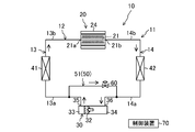
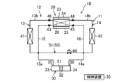
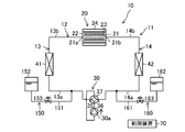
- FIG. 1 is a piping diagram schematically illustrating the configuration of the magnetic refrigerator according to the first embodiment.
- FIG. 2 is a piping diagram schematically illustrating a configuration of the magnetic refrigeration apparatus according to Embodiment 1, and illustrates a flow of a heat medium in a heating operation.
- FIG. 3 is a piping diagram schematically illustrating the configuration of the magnetic refrigeration apparatus according to Embodiment 1, and illustrates the flow of the heat medium in the cooling operation.
- FIG. 4 is a diagram corresponding to FIG. 1 according to the second embodiment.
- FIG. 5 is a diagram corresponding to FIG. 1 according to the third embodiment.
- FIG. 6 is a diagram corresponding to FIG. 1 according to the first modification.
- FIG. 7 is a diagram corresponding to FIG. 1 according to the second modification.
- FIG. 8 is a diagram corresponding to FIG. 1 according to the third modification.
- FIG. 9 is a diagram corresponding to FIG. 1 according to the fourth modification.
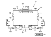
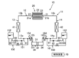
- FIG. 10 is a piping diagram schematically illustrating a configuration of a magnetic refrigeration apparatus according to Embodiment 4.
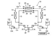
- FIG. 11 is a piping diagram schematically illustrating a configuration of a magnetic refrigeration apparatus according to Embodiment 4, and illustrates a flow of a heat medium in a heating operation.
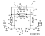
- FIG. 12 is a piping diagram schematically illustrating a configuration of a magnetic refrigeration apparatus according to Embodiment 4, and illustrates a flow of a heat medium in a cooling operation.
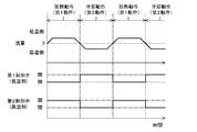
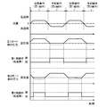
- FIG. 13 is a timing chart regarding the flow rate, the first control valve, and the second control valve in the control operation according to the fourth embodiment.
- FIG. 10 is a piping diagram schematically illustrating a configuration of a magnetic refrigeration apparatus according to Embodiment 4.
- FIG. 11 is a piping diagram schematically illustrating a configuration of a
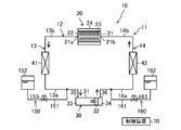
- FIG. 14 is a diagram corresponding to FIG. 10 according to the fifth embodiment.
- FIG. 15 is a timing chart regarding the flow rate, the pressure, the first control valve, and the second control valve in the control operation according to the fifth embodiment.
- FIG. 16 is a timing chart regarding the flow rate, the pressure, the first control valve, and the second control valve in the control operation according to the sixth embodiment.
- FIG. 17 is a diagram corresponding to FIG. 10 according to the seventh embodiment.
- FIG. 18 is a diagram corresponding to FIG. 10 according to the eighth embodiment.
- FIG. 19 is a diagram corresponding to FIG. 10 according to the fifth modification.
- FIG. 20 is a diagram corresponding to FIG. 10 according to the sixth modification.
- FIG. 21 is a diagram corresponding to FIG. 10 according to the seventh modification.
- FIG. 22 is a diagram corresponding to FIG. 10 according to another embodiment.
- Embodiment 1 The magnetic refrigeration apparatus (10) of the present embodiment adjusts the temperature of the heat medium using the magnetocaloric effect.
- the magnetic refrigerator (10) is applied to, for example, an air conditioner.
- the magnetic refrigerator (10) includes a heat medium circuit (11) filled with a heat medium.
- Each component of the heat medium circuit (11) is connected to each other via a pipe.
- the heat medium circuit (11) includes a closed loop main flow path (12) and a branch flow path (50) branched from the main flow path (12).
- the magnetic refrigeration apparatus (10) includes a magnetic refrigeration unit (20) (magnetic refrigeration unit), a pump (30), a low-temperature heat exchanger (41), and a high-temperature heat exchanger (42).
- the pump (30), the low-temperature side heat exchanger (41), the temperature control flow path (21) of the magnetic refrigeration unit (20), and the high-temperature side heat exchanger (42) are arranged in this order. Connected.
- the main flow path (12) includes a low-temperature flow path (13) and a high-temperature flow path (14).
- the low temperature side flow path (13) is formed between one end of the temperature control flow path (21) of the magnetic refrigeration unit (20) and the first port (35) of the pump (30).
- the low temperature side channel (13) forms a first channel.
- One end of the temperature control flow path (21) forms a first connection port (21a).
- the high temperature side flow path (14) is formed between the other end of the temperature control flow path (21) of the magnetic refrigeration unit (20) and the second port (36) of the pump (30).
- the high temperature side channel (14) forms a second channel.
- the other end of the temperature control flow path (21) forms a second connection port (21b).
- the low temperature side channel (13) may be the second channel
- the high temperature side channel (14) may be the first channel.
- the low temperature side flow path (13) includes a first pump side pipe (13a) formed between the low temperature side heat exchanger (41) and the pump (30), a low temperature side heat exchanger (41) and a magnetic refrigeration unit. And a first magnetic side pipe (13b) formed between the unit and the unit (20).
- the high temperature side flow path (14) includes a second pump side pipe (14a) formed between the high temperature side heat exchanger (42) and the pump (30), and the high temperature side heat exchanger (42) and the magnetic refrigeration. And a second magnetic side pipe (14b) formed between the first magnetic section and the second section (20).
- the pump (30) of the present embodiment constitutes a fluid transfer mechanism that reciprocates the heat medium in the main flow path (12). That is, the pump (30) performs the first operation of transporting the heat medium in the main flow path (12) in the first direction (the direction indicated by the solid arrow in FIG. 2), and the heat medium in the main flow path (12) in the first direction. And the second operation of transporting in the opposite second direction (the direction indicated by the solid arrow in FIG. 3) is alternately repeated.
- the pump (30) of the present embodiment is constituted by a reciprocating piston pump.
- the pump (30) includes a pump case (31) and a piston (32) arranged to be able to advance and retreat inside the pump case (31).
- the piston (32) partitions the inside of the pump case (31) into a first chamber (33) and a second chamber (34).
- a first port (35) communicating with the first chamber (33) and a second port (36) communicating with the second chamber (34) are formed in the pump case (31).
- the first port (35) is connected to the low temperature side channel (13), and the second port (36) is connected to the high temperature side channel (14).
- the piston (32) is driven by a drive mechanism not shown.
- the drive mechanism has a rod connected to the piston (32), a crank connected to the rod, and an electric motor driving the crank.
- the motor rotates the crank, the rod moves forward and backward.
- the reciprocating motion of the piston (32) is performed in the pump case (31), and the first operation and the second operation are alternately repeated.
- the piston (32) moves toward the first port (35), and the volume of the first chamber (33) decreases and the volume of the second chamber (34) increases.
- the heat medium in the first chamber (33) is discharged to the low temperature side channel (13) through the first port (35).
- the heat medium in the high temperature side flow path (14) is sucked into the second chamber (34) through the second port (36).
- the piston (32) moves toward the second port (36), and the volume of the second chamber (34) decreases and the volume of the first chamber (33) increases.
- the heat medium in the second chamber (34) is discharged to the high temperature side channel (14) through the second port (36).
- the heat medium in the low temperature side channel (13) is sucked into the first chamber (33) through the first port (35).
- the low-temperature side heat exchanger (41) exchanges heat between the heat medium cooled by the magnetic refrigeration unit (20) and a predetermined object to be cooled (for example, a secondary refrigerant or air).
- the high-temperature side heat exchanger (42) exchanges heat between the heat medium heated by the magnetic refrigeration unit (20) and a predetermined heating target (for example, a secondary refrigerant or air).
- the magnetic refrigeration unit (20) includes a bed (22), a magnetic work material (23) arranged in a temperature control flow path (21) in the bed (22), and a magnetic field fluctuation applied to the magnetic work material (23). And a magnetic field modulating section (24) to be provided.
- the bed (22) is a hollow case or column, and is filled with a magnetic work substance (23).
- the magnetic working material (23) has a property of generating heat when a magnetic field is applied or when the applied magnetic field is strong, and absorbing heat when the magnetic field is removed or the applied magnetic field is weakened.
- the magnetic field modulator (24) adjusts the strength of the magnetic field applied to the magnetic work material (23).
- the magnetic field modulation unit (24) is formed of, for example, an electromagnet capable of modulating a magnetic field.
- the magnetic field modulating unit (24) applies a magnetic field to the magnetic work material (23) or increases the applied magnetic field, and removes or applies the magnetic field applied to the magnetic work material (23). And a second modulation operation for weakening the applied magnetic field.
- the branch channel (50) is a channel for adjusting the pressure of the main channel (12).
- the branch flow path (50) is a flow path for adjusting the flow rate of the heat medium flowing through the temperature control flow path (21) of the magnetic refrigeration unit (20). That is, the branch flow path (50) is configured such that the heat medium in the main flow path (12) flows in, and adjusts the flow rate in the temperature control flow path (21) in accordance with the flow rate of the divided heat medium.
- the branch flow path (50) of the present embodiment constitutes an intermediate flow path (51) connected between the low-temperature flow path (13) and the high-temperature flow path (14).
- the intermediate flow path (51) forms a communication path that connects the low-temperature flow path (13) and the high-temperature flow path (14).
- One end of the intermediate flow path (51) is connected to the first pump side pipe (13a).
- the other end of the intermediate flow path (51) is connected to the second pump side pipe (14a).
- a control valve (60) is connected to the branch flow path (50).
- the control valve (60) constitutes a flow path resistance adjusting unit that adjusts the flow path resistance so as to adjust the flow rate of the heat medium diverted to the branch flow path (50).
- the control valve (60) is formed of, for example, a motor-operated valve, and is configured such that its opening can be adjusted.
- the control valve (60) is connected to the high temperature side flow path (14) in the branch flow path (50). That is, the control valve (60) is connected to a position closer to the high-temperature side flow path (14) than the low-temperature side flow path (13) in the intermediate flow path (51). By disposing the control valve (60) near the high-temperature side flow path (14), it is possible to suppress the heat generated from the control valve (60) from moving to the low-temperature heat medium in the low-temperature side flow path (13).
- Va be the entire internal volume of the intermediate flow path (51), which is a communication path.
- the capacity (discharge amount) of the heat medium discharged from the pump (30) in one first operation is Vd1.
- the capacity (discharge amount) of the heat medium discharged from the pump (30) in one second operation is Vd2.
- the discharge amount Vd1 of the first operation of the pump (30) is equal to the discharge flow rate Vd2 of the second operation of the pump (30).
- the entire internal volume Va of the intermediate flow path (51) is set larger than Vd1 and Vd2.
- the magnetic refrigerator (10) includes a control device (70) for controlling the control valve (60).
- the control device (70) is configured using a microcomputer and a memory device (specifically, a semiconductor memory) that stores software for operating the microcomputer.
- the control device (70) adjusts the opening of the control valve (60) based on a predetermined control signal.
- the magnetic refrigerator (10) alternately repeats the heating operation shown in FIG. 2 and the cooling operation shown in FIG.
- the cycle of switching between the heating operation and the cooling operation is set to about 1 second.
- the pump (30) performs the first operation, and the magnetic field modulator (24) performs the first modulation operation. That is, in the heating operation, the heat medium is discharged from the first port (35) of the pump (30). At the same time, a magnetic field is applied to the magnetic work substance (23), or the applied magnetic field is strengthened.
- the heat medium in the low temperature side flow path (13) becomes the temperature control flow path of the magnetic refrigeration unit (20). It flows into the first connection port (21a) of (21).
- the heat medium flowing through the temperature control flow path (21) is heated by the magnetic work substance (23).
- the heat medium heated in the temperature control flow path (21) flows out of the second connection port (21b) to the high temperature side flow path (14), and flows through the high temperature side heat exchanger (42).
- a predetermined heating target (secondary refrigerant, air, or the like) is heated by a high-temperature heat medium.
- the heat medium in the high temperature side flow path (14) is drawn into the second chamber (34) from the second port (36) of the pump (30).
- the pump (30) performs the second operation and the magnetic field modulator (24) performs the second modulation operation. That is, in the heating operation, the magnetic field of the magnetic working material (23) is removed or the applied magnetic field is weakened at the same time when the heat medium is discharged from the second port (36) of the pump (30).
- the heat medium in the high-temperature side flow path (14) becomes the temperature control flow path of the magnetic refrigeration unit (20). It flows into the second connection port (21b) of (21).
- the magnetic work material (23) takes away the heat of the surroundings. Therefore, the heat medium flowing through the temperature control flow path (21) is cooled by the magnetic work material (23).
- the heat medium cooled in the temperature control flow path (21) flows out of the first connection port (21a) to the low-temperature side flow path (13), and flows through the low-temperature side heat exchanger (41).
- a predetermined cooling target (secondary refrigerant, air, or the like) is cooled by a low-temperature heat medium.
- the heat medium in the low temperature side flow path (13) is sucked into the first chamber (33) from the first port (35) of the pump (30).
- the flow rate of the temperature control flow path (21) is appropriately adjusted.
- the temperature of the heat medium heated by the magnetic work substance (23) can be appropriately adjusted.
- the control valve (60) when the control valve (60) is opened at a predetermined opening, a part of the heat medium in the high-temperature side flow path (14) is diverted to the branch flow path (50), as indicated by a broken arrow in FIG. I do. Therefore, the flow rate Qc of the temperature control flow path (21) decreases.
- the flow rate of the temperature control flow path (21) is appropriately adjusted.
- the temperature of the heat medium cooled by the magnetic work substance (23) can be appropriately adjusted.
- the pressure of the main flow path (12) can be adjusted by sending a part of the heat medium in the main flow path (12) to the branch flow path (50).
- the pressure of the main flow path (12) can be adjusted by flowing the heat medium in the main flow path (12) into the branch flow path (50).
- a discharge flow rate of a fluid transfer mechanism such as a pump is used. May be adjusted.
- a fluid transfer mechanism such as a pump
- the flow rate of the heat medium in the temperature control flow path (21) can be adjusted by flowing the heat medium in the main flow path (12) into the branch flow path (50). Therefore, even with a fixed-capacity type fluid transfer mechanism such as a reciprocating pump (30), the flow rate of the temperature control flow path (21) can be adjusted.
- the flow rate of the heat medium flowing through the branch flow path (50) can be finely adjusted, and the temperature control flow path (21) The flow rate of the heat medium flowing through the can be finely adjusted.
- the branch flow path (50) is an intermediate flow path (51) connected between the low-temperature flow path (13) and the high-temperature flow path (14). For this reason, the heat medium can be divided by both the heating operation and the cooling operation by the single branch flow path (50).
- the intermediate flow path (51) is a communication path that connects the low-temperature flow path (13) and the high-temperature flow path (14). Therefore, the suction pressure of the pump (30) can be applied to the intermediate flow path (51), and the heat medium can be quickly diverted to the branch flow path (50). Specifically, for example, in the heating operation, the suction pressure on the second port (36) side of the pump (30) acts on the high temperature side end of the branch flow path (50). Therefore, a part of the heat medium discharged from the first port (35) quickly flows into the branch flow path (50). Further, for example, in the cooling operation, the suction pressure on the first port (35) side of the pump (30) acts on the low temperature side end of the branch flow path (50).
- the internal volume of the branch flow path (50), which is a communication passage, is larger than the discharge amount of the pump (30) in the first operation and the second operation. For this reason, in the first operation, it is possible to prevent the heat medium in the low-temperature side channel (13) from flowing out to the high-temperature side channel (14) via the branch channel (50). In the second operation, it is possible to prevent the heat medium in the high temperature side flow path (14) from flowing out to the low temperature side flow path (13) via the branch flow path (50). As a result, it is possible to prevent the heat medium on the high temperature side and the heat medium on the low temperature side from being mixed, and to avoid heat loss due to the mixing of these heat mediums.
- the control valve (60) is arranged closer to the high temperature side flow path (14) in the branch flow path (50). Therefore, it is possible to suppress the heat generated from the control valve (60) from moving to the heat medium in the low-temperature side flow path (13). As a result, it is possible to suppress an increase in the temperature of the heat medium in the low-temperature side flow path (13) due to the heat generated by the control valve (60).
- branch flow path (50) which is the intermediate flow path (51) is between the pump (30) and the low-temperature heat exchanger (41) in the low-temperature flow path (13) (that is, the first pump-side pipe). (13a)), and the other end is connected between the pump (30) and the high-temperature side heat exchanger (42) in the high-temperature side flow path (14) (that is, the second pump-side pipe (14a)).
- the heat medium after passing through the low-temperature side heat exchanger (41) does not flow to the branch flow path (50). Therefore, it is possible to prevent so-called cold heat of the heat medium in the low-temperature side heat exchanger (41) from being discarded to the branch flow path (50).
- the heat medium that has passed through the high-temperature side heat exchanger (42) does not flow to the branch flow path (50). Therefore, it is possible to avoid that the heat of the heat medium in the high-temperature side heat exchanger (42) is discarded toward the branch flow path (50).
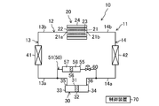
- the branch flow path (50) of the second embodiment is an intermediate flow path connected between the low-temperature flow path (13) and the high-temperature flow path (14), as in the first embodiment. (51).
- the intermediate flow path (51) of the second embodiment does not strictly communicate the low-temperature flow path (13) and the high-temperature flow path (14).
- a cylindrical cylinder (55) is connected to the branch channel (50) of the second embodiment.
- the cylinder (55) communicates the low-temperature side channel (13) and the high-temperature side channel (14) by the space inside.
- a columnar partition member (56) is provided inside the cylinder (55) so as to be able to advance and retreat.
- the partition member (56) fits inside the cylinder (55) and partitions the inside of the cylinder (55) into two parts. Specifically, the inside of the cylinder (55) is partitioned by a partition member (56) into a first internal channel (57) communicating with the low-temperature channel (13) and a second internal channel (57) communicating with the high-temperature channel (14). It is partitioned into two internal flow paths (58).
- the cylinder (55) reciprocates inside the cylinder (55) due to the pressure difference between the first internal flow path (57) and the second internal flow path (58). As a result, the volumes of the first internal channel (57) and the second internal channel (58) change.
- the maximum volume Vmax1 of the first internal flow path (57) is larger than the discharge amount Vd1 of the pump (30) in one first operation.
- the maximum volume Vmax2 of the second internal flow path (58) is larger than the discharge amount Vd2 of the pump (30) in one second operation.
- a control valve (60) is connected to the branch flow path (50) in series with the cylinder (55).
- the control valve (60) is connected between the cylinder (55) and the high temperature side flow path (14). Thereby, it is possible to suppress the heat of the control valve (60) from moving to the heat medium in the low-temperature side flow path (13).
- the opening of the control valve (60) by adjusting the opening of the control valve (60), the flow rate of the heat medium diverted to the branch flow path (50) can be adjusted, and thus the flow rate of the heat medium in the temperature control flow path (21). Is adjusted.
- the heat medium in the low-temperature side flow path (13) is divided into the branch flow path (50) and flows into the first internal flow path (57) of the cylinder (55).
- the suction pressure on the second port (36) side of the pump (30) acts on the second internal flow path (58). Therefore, the partition member (56) moves toward the high-temperature side flow path (14), and the volume of the first internal flow path (57) increases.
- the heat medium in the low temperature side channel (13) accumulates in the first internal channel (57).
- the maximum volume Vmax1 of the first internal flow path (57) is larger than the discharge amount Vd1 of the pump (30) in the first operation, the heat medium of the low temperature side flow path (13) is transferred to the first internal flow path. (57). In this way, the flow of the heat medium in the low temperature side flow path (13) to the branch flow path (50) can be adjusted to the flow rate of the heat medium in the temperature control flow path (21).
- the heat medium in the high-temperature side flow path (14) is divided into the branch flow path (50) and flows into the second internal flow path (58) of the cylinder (55).
- the suction pressure on the first port (35) side of the pump (30) acts on the first internal flow path (57). Therefore, the partition member (56) moves toward the low-temperature side flow path (13), and the volume of the second internal flow path (58) increases. Accordingly, the heat medium in the high-temperature side flow path (14) accumulates in the second internal flow path (58).
- the heat medium of the high temperature side flow path (14) is transferred to the second internal flow path. (58).
- the flow rate of the heat medium in the temperature control flow path (21) can be adjusted.
- the partition member (56) Since the first internal flow path (57) and the second internal flow path (58) are partitioned by the partition member (56), the heat medium of the low-temperature flow path (13) and the heat medium of the high-temperature flow path (14) are separated. Mixing with the medium can be reliably avoided. Therefore, it is possible to avoid causing heat loss due to such mixing of the heat medium.
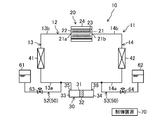
- one branch channel (52, 53) is connected to each of the low-temperature channel (13) and the high-temperature channel (14).
- one end of a first branch pipe (52), which is a branch flow path is connected to the low temperature side flow path (13).
- a first reservoir (61) is connected to the other end of the first branch pipe (52).
- One end of a second branch pipe (53), which is a branch flow path, is connected to the high temperature side flow path (14).
- a second reservoir (62) is connected to the other end of the second branch pipe (53).
- the first reservoir (61) and the second reservoir (62) are constituted by containers capable of storing a heat medium.
- the first reservoir (61) and the second reservoir (62) are provided with a pressure relief valve (not shown).
- the actual volume Vr1 inside the first reservoir (61) is equal to the actual volume Vr2 inside the second reservoir (62).
- These actual volumes Vr1 and Vr2 are larger than twice the discharge amounts Vd1 and Vd2 of the pump (30) in the first operation and the second operation.
- the first branch pipe (52) is connected to a first control valve (63), which is a flow path resistance adjuster.
- the second branch pipe (53) is connected to a second control valve (64) that is a flow path resistance adjusting unit.
- the first control valve (63) and the second control valve (64) are configured by, for example, motor-operated valves, and are configured such that their opening degrees can be adjusted.
- the control device (70) adjusts the opening of the first control valve (63) during the heating operation, and adjusts the opening of the second control valve (64) during the cooling operation.
- the heat medium in the low temperature side flow path (13) is diverted to the first branch pipe (52).
- the heat medium in the first branch pipe (52) accumulates in the first reservoir (61).
- the actual volume Vr1 of the first reservoir (61) is larger than twice the discharge amount of the pump (30) in the first operation or the second operation, a sufficient amount of the heat medium is filled in the first reservoir (61). Can be stored.
- the heat medium stored in the second reservoir (62) returns to the high-temperature side flow path (14) and is sucked into the second port (36) of the pump (30). Since the actual volume Vr2 of the second reservoir (62) is larger than twice the discharge amount Vd2 of the pump (30) in the first operation or the second operation, the heat medium of the second reservoir (62) becomes empty. Can be avoided.
- the second control valve (64) when the second control valve (64) is opened at a predetermined opening in the cooling operation, the heat medium in the high-temperature side flow path (14) is diverted to the second branch pipe (53).
- the heat medium in the second branch pipe (53) accumulates in the second reservoir (62).
- the actual volume Vr2 of the second reservoir (62) is larger than twice the discharge amount Vd2 of the pump (30) in the second operation, it is necessary to sufficiently store the heat medium in the second reservoir (62). Can be.
- the flow rate of the heat medium of the temperature control flow path (21) can be adjusted.
- the heat medium stored in the first reservoir (61) returns to the low temperature side flow path (13) and is sucked into the first port (35) of the pump (30). Since the actual volume Vr1 of the first reservoir (61) is larger than twice the discharge amount of the pump (30) in the first operation or the second operation, the heat medium of the first reservoir (61) becomes empty. Can be avoided.
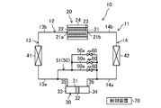
- Modification Example 1 shown in FIG. 6 differs from Embodiment 1 in the configurations of the branch flow path (50) (the intermediate flow path (51)) and the flow path resistance adjusting unit (control valve).
- the branch flow path (50) of the first modification includes a plurality of parallel pipes (50a, 50a, 50a) connected in parallel with each other. In this example, three parallel pipes (50a) are provided in the branch flow path (50).
- One control valve (60) is connected to each parallel pipe (50a).
- Each control valve (60) of this example is constituted by, for example, an electromagnetic on-off valve, and opens and closes the corresponding parallel pipe (50a).
- Each control valve (60) constitutes a flow path resistance adjusting unit that adjusts the flow path resistance of the branch flow path (50).
- the flow rate of the heat medium in the temperature control flow path (21) is adjusted according to the open / close state of each control valve (60). For example, when all three control valves (60) are closed, the flow rate of the heat medium in the temperature control flow path (21) becomes equal to the discharge rate of the pump (30). When one of the three control valves (60) is opened and the other is closed, the flow rate of the heat medium in the branch flow path (50) increases, and the flow rate in the temperature control flow path (21) decreases. I do. When two of the three control valves (60) are opened and the rest are closed, the flow rate of the heat medium in the branch flow path (50) further increases, and the heat medium in the temperature control flow path (21) increases. Is further reduced. Thus, in the modified example, as the number of control valves (60) to be opened increases, the flow rate of the heat medium in the branch flow path (50) decreases.
- the plurality of parallel pipes (50a) and the plurality of control valves (60) according to the first modification may be employed in the branch flow path (50) of the second or third embodiment.
- the inflow end of the heating channel (25) is connected to the first pump side pipe (13a) via the low temperature side bypass channel (15).
- a first check valve (43) is connected to the low temperature side bypass flow path (15). The first check valve (43) allows only the flow of the heat medium toward the heating flow path (25) in the low-temperature side bypass flow path (15), and prohibits the reverse flow.
- the outflow end of the heating channel (25) is connected to the high-temperature side heat exchanger (42) via the second magnetic side pipe (14b).
- a second check valve (44) is connected to the second magnetic side pipe (14b). The second check valve (44) allows only the flow of the heat medium toward the high-temperature side heat exchanger (42) in the second magnetic pipe (14b), and prohibits the reverse flow.
- the inflow end of the cooling channel (26) is connected to the second pump-side pipe (14a) via the high-temperature-side bypass channel (16).
- a third check valve (45) is connected to the high temperature side bypass flow path (16). The third check valve (45) allows only the flow of the heat medium toward the cooling flow path (26) in the high temperature side bypass flow path (16), and prohibits the reverse flow.
- the outflow end of the cooling channel (26) is connected to the low temperature side heat exchanger (41) via the first magnetic side pipe (13b).
- a fourth check valve (46) is connected to the first magnetic side pipe (13b). The fourth check valve (46) allows only the flow of the heat medium toward the low-temperature side heat exchanger (41) in the first magnetic side pipe (13b), and prohibits the reverse flow.
- the heat medium conveyed by the pump (30) during the first operation flows through the heating flow path (25) after passing through the low-temperature bypass flow path (15).
- the heat medium is heated by the magnetic work substance (23).
- the heated heat medium is conveyed to the high-temperature side heat exchanger (42) and used for heating the object to be heated.
- the heat medium in the high temperature side flow path (14) is sucked into the second port (36) of the pump (30).
- the flow rate of the heat medium flowing through the heating flow path (25) can be adjusted by diverting the heat medium into the branch flow path (50).
- the heat medium conveyed by the pump (30) during the second operation flows through the cooling flow path (26) after passing through the high-temperature side bypass flow path (16).
- the heat medium is cooled by the magnetic work substance (23).
- the cooled heat medium is conveyed to the low-temperature side heat exchanger (41) and is used for cooling the object to be cooled.
- the heat medium in the low temperature side channel (13) is sucked into the first port (35) of the pump (30).
- the flow rate of the heat medium flowing through the cooling flow path (26) can be adjusted by diverting the heat medium into the branch flow path (50).
- the heat medium circuit (11) according to the second modification may be employed in the second and third embodiments.
- ⁇ Modification 3> In the third modification shown in FIG. 8, a plurality (two in this example) of magnetic refrigeration units (20) are connected in parallel in the same heat medium circuit (11) as the second modification. Therefore, in the heating operation, the heat medium in the low-temperature side flow path (13) is heated in the heating flow paths (25) of the two magnetic refrigeration units (20), and then transported to the high-temperature side heat exchanger (42). Is done. In the cooling operation, the heat medium in the high-temperature side flow path (14) is cooled in the cooling flow paths (26) of the two magnetic refrigeration units (20), respectively, and then transferred to the low-temperature side heat exchanger (41). .
- the flow rate of the heat medium flowing through each heating flow path (25) can be adjusted by adjusting the flow rate of the heat medium flowing to the branch flow path (50) in the heating operation.
- the flow rate of the heat medium flowing through each cooling flow path (26) can be adjusted.
- the heat medium circuit (11) according to the third modification may be adopted in the second and third embodiments.
- Modification 4 shown in FIG. 9 is the same as Modification 2 except that a plurality (two in this example) of magnetic refrigeration units (20) are connected in series. Accordingly, in the heating operation, the heat medium in the low-temperature side flow path (13) is sequentially heated in each heating flow path (25) of each magnetic refrigeration unit (20), and then transported to the high-temperature side heat exchanger (42). Is done. In the cooling operation, the heat medium in the high-temperature side flow path (14) is sequentially cooled in each cooling flow path (26) of each magnetic refrigeration unit (20), and then transferred to the low-temperature side heat exchanger (41). .
- the flow rate of the heat medium flowing through each heating flow path (25) can be adjusted by adjusting the flow rate of the heat medium diverted to the branch flow path (50) in the heating operation.
- the flow rate of the heat medium flowing through each cooling flow path (26) can be adjusted.
- the heat medium circuit (11) according to the fourth modification may be adopted in the second and third embodiments.
- Embodiment 4 The magnetic refrigeration apparatus (10) of the fourth embodiment adjusts the temperature of the heat medium using the magnetocaloric effect.
- the magnetic refrigerator (10) is applied to, for example, an air conditioner.
- the magnetic refrigerator (10) includes a heating medium circuit (11) filled with a heating medium.
- Each component of the heat medium circuit (11) is connected to each other via a pipe.
- the heat medium circuit (11) includes a closed loop main flow path (12) and two branch flow paths (50, 60) branched from the main flow path (12).
- the magnetic refrigeration apparatus (10) includes a magnetic refrigeration unit (20) (magnetic refrigeration unit), a pump (30), a low-temperature heat exchanger (41), and a high-temperature heat exchanger (42).
- the pump (30), the low-temperature side heat exchanger (41), the temperature control flow path (21) of the magnetic refrigeration unit (20), and the high-temperature side heat exchanger (42) are arranged in this order. Connected.
- the main flow path (12) includes a low-temperature flow path (13) and a high-temperature flow path (14).
- the low temperature side flow path (13) is formed between one end of the temperature control flow path (21) of the magnetic refrigeration unit (20) and the first port (35) of the pump (30).
- the low temperature side channel (13) constitutes a first channel.
- One end of the temperature control flow path (21) forms a first connection port (21a).
- the high temperature side flow path (14) is formed between the other end of the temperature control flow path (21) of the magnetic refrigeration unit (20) and the second port (36) of the pump (30).
- the high temperature side channel (14) forms a second channel.
- the other end of the temperature control flow path (21) forms a second connection port (21b).
- the low temperature side channel (13) may be the second channel
- the high temperature side channel (14) may be the first channel.
- the low temperature side flow path (13) includes a first pump side pipe (13a) formed between the low temperature side heat exchanger (41) and the pump (30), a low temperature side heat exchanger (41) and a magnetic refrigeration system. And a first magnetic side pipe (13b) formed between the unit and the unit (20).
- the high temperature side flow path (14) includes a second pump side pipe (14a) formed between the high temperature side heat exchanger (42) and the pump (30), and the high temperature side heat exchanger (42) and the magnetic refrigeration. And a second magnetic side pipe (14b) formed between the first magnetic section and the second section (20).
- the pump (30) of the present embodiment constitutes a fluid transfer mechanism that reciprocates the heat medium in the main flow path (12). That is, the pump (30) performs the first operation of transporting the heat medium in the main flow path (12) in the first direction (the direction indicated by the solid arrow in FIG. 11) and the heat medium in the main flow path (12) in the first direction. And the second operation of transporting in the opposite second direction (the direction indicated by the solid arrow in FIG. 12) is alternately repeated.
- the pump (30) of the present embodiment is constituted by a reciprocating piston pump.
- the pump (30) includes a pump case (31) and a piston (32) arranged to be able to advance and retreat inside the pump case (31).
- the piston (32) partitions the inside of the pump case (31) into a first chamber (33) and a second chamber (34).
- a first port (35) communicating with the first chamber (33) and a second port (36) communicating with the second chamber (34) are formed in the pump case (31).
- the first port (35) is connected to the low temperature side channel (13), and the second port (36) is connected to the high temperature side channel (14).
- the piston (32) is driven by a drive mechanism not shown.
- the drive mechanism has a rod connected to the piston (32), a crank connected to the rod, and an electric motor driving the crank.
- the motor rotates the crank, the rod moves forward and backward.
- the reciprocating motion of the piston (32) is performed in the pump case (31), and the first operation and the second operation are alternately repeated.
- the piston (32) moves toward the first port (35), and the volume of the first chamber (33) decreases and the volume of the second chamber (34) increases.
- the heat medium in the first chamber (33) is discharged to the low temperature side channel (13) through the first port (35).
- the heat medium in the high temperature side flow path (14) is sucked into the second chamber (34) through the second port (36).
- the piston (32) moves toward the second port (36), and the volume of the second chamber (34) decreases and the volume of the first chamber (33) increases.
- the heat medium in the second chamber (34) is discharged to the high temperature side channel (14) through the second port (36).
- the heat medium in the low temperature side channel (13) is sucked into the first chamber (33) through the first port (35).
- the low-temperature side heat exchanger (41) exchanges heat between the heat medium cooled by the magnetic refrigeration unit (20) and a predetermined object to be cooled (for example, a secondary refrigerant or air).
- the high-temperature side heat exchanger (42) exchanges heat between the heat medium heated by the magnetic refrigeration unit (20) and a predetermined heating target (for example, a secondary refrigerant or air).
- the magnetic refrigeration unit (20) includes a bed (22), a magnetic work material (23) arranged in a temperature control flow path (21) in the bed (22), and a magnetic field fluctuation applied to the magnetic work material (23). And a magnetic field modulating section (24) to be provided.
- the bed (22) is a hollow case or column, and is filled with a magnetic work substance (23).
- the magnetic working material (23) has a property of generating heat when a magnetic field is applied or when the applied magnetic field is strong, and absorbing heat when the magnetic field is removed or the applied magnetic field is weakened.
- the magnetic field modulator (24) adjusts the strength of the magnetic field applied to the magnetic work material (23).
- the magnetic field modulation unit (24) is formed of, for example, an electromagnet capable of modulating a magnetic field.
- the magnetic field modulating unit (24) applies a magnetic field to the magnetic work material (23) or increases the applied magnetic field, and removes or applies the magnetic field applied to the magnetic work material (23). And a second modulation operation for weakening the applied magnetic field.
- the first branch flow path (150) and the second branch flow path (160) are connected to the heat medium circuit (11).
- the first branch channel (150) is connected to the low temperature channel (13).
- the second branch channel (160) is connected to the high temperature side channel (14).
- the first branch channel (150) includes a third branch pipe (151) and a first accumulator (152).
- One end of the third branch pipe (151) is connected to the first pump side pipe (13a) of the low temperature side flow path (13).
- the first accumulator (152) is connected to the other end of the third branch pipe (151).
- the first accumulator (152) forms a container into which the heat medium can flow.
- a third control valve (153) is connected to the third branch pipe (151).
- the third control valve (153) is configured by, for example, an electromagnetic on-off valve. That is, the third control valve (153) is switched between a closed state in which the first branch flow path (150) is closed and an open state in which the first branch flow path (150) is opened.
- the second branch channel (160) includes a fourth branch pipe (161) and a second accumulator (162).
- One end of the fourth branch pipe (161) is connected to the second pump side pipe (14a) of the high temperature side flow path (14).
- the second accumulator (162) is connected to the other end of the fourth branch pipe (161).
- the second accumulator (162) forms a container into which the heat medium can flow.
- a fourth control valve (163) is connected to the fourth branch pipe (161).
- the fourth control valve (163) is composed of, for example, an electromagnetic on-off valve. That is, the fourth control valve (163) is switched between a closed state in which the second branch flow path (160) is closed and an open state in which the second branch flow path (160) is opened.
- the magnetic refrigerator (10) includes a control device (70) for controlling the third control valve (153) and the fourth control valve (163).
- the control device (70) is configured using a microcomputer and a memory device (specifically, a semiconductor memory) that stores software for operating the microcomputer.
- the control device (70) of the present embodiment controls the third control valve (153) and the fourth control valve (163) in synchronization with the timing of the first operation and the second operation. Specifically, when the first operation is performed, the control device (70) closes the third control valve (153) on the discharge side of the pump (30). In addition, when the first operation is performed, the control device (70) opens the fourth control valve (163) on the suction side of the pump (30). On the other hand, when the second operation is performed, the control device (70) closes the fourth control valve (163) on the discharge side of the pump (30). In addition, when the second operation is performed, the control device (70) opens the third control valve (153) on the suction side of the pump (30) (see FIG. 13, details will be described later).
- the magnetic refrigerator (10) alternately repeats the heating operation shown in FIG. 11 and the cooling operation shown in FIG.
- the cycle of switching between the heating operation and the cooling operation is set to about 1 second.
- the pump (30) performs the first operation, and the magnetic field modulator (24) performs the first modulation operation. That is, in the heating operation, the heat medium is discharged from the first port (35) of the pump (30). At the same time, a magnetic field is applied to the magnetic work substance (23), or the applied magnetic field is strengthened.
- the heat medium in the low temperature side flow path (13) becomes the temperature control flow path of the magnetic refrigeration unit (20). It flows into the first connection port (21a) of (21).
- the heat medium flowing through the temperature control flow path (21) is heated by the magnetic work substance (23).
- the heat medium heated in the temperature control flow path (21) flows out of the second connection port (21b) to the high temperature side flow path (14), and flows through the high temperature side heat exchanger (42).
- a predetermined heating target (secondary refrigerant, air, or the like) is heated by a high-temperature heat medium.
- the heat medium in the high temperature side flow path (14) is drawn into the second chamber (34) from the second port (36) of the pump (30).
- the pump (30) performs the second operation and the magnetic field modulator (24) performs the second modulation operation. That is, in the heating operation, the magnetic field of the magnetic working material (23) is removed or the applied magnetic field is weakened at the same time when the heat medium is discharged from the second port (36) of the pump (30).
- the heat medium in the high-temperature side flow path (14) becomes the temperature control flow path of the magnetic refrigeration unit (20). It flows into the second connection port (21b) of (21).
- the magnetic work material (23) takes away the heat of the surroundings. Therefore, the heat medium flowing through the temperature control flow path (21) is cooled by the magnetic work material (23).
- the heat medium cooled in the temperature control flow path (21) flows out of the first connection port (21a) to the low-temperature side flow path (13), and flows through the low-temperature side heat exchanger (41).
- a predetermined cooling target (secondary refrigerant, air, or the like) is cooled by a low-temperature heat medium.
- the heat medium in the low temperature side flow path (13) is sucked into the first chamber (33) from the first port (35) of the pump (30).
- the third control valve (153) and the fourth control valve (163) are controlled in synchronization with the first operation and the second operation.
- the third control valve (153) and the fourth control valve (163) are controlled in synchronization with the heating operation and the cooling operation.
- the third control valve (153) is closed, and the fourth control valve (163) is open.
- the third control valve (153) is open, and the fourth control valve (163) is closed.
- the third control valve (153) is closed. Therefore, the heat medium discharged from the first port (35) of the pump (30) during the first operation does not flow through the first branch flow path (150). Therefore, the heat medium in the low-temperature side channel (13) is not sent to the first branch channel (150) but is supplied to the temperature control channel (21). Therefore, it is possible to suppress a decrease in the flow rate of the heat medium flowing through the temperature control flow path (21), and it is possible to supply a sufficient flow rate of the heat medium to the high-temperature side heat exchanger (42). As a result, the heating capacity of the high-temperature side heat exchanger (42) can be sufficiently ensured.
- the fourth control valve (163) is opened. Therefore, the heat medium in the second accumulator (162) is sucked into the second port (36) of the pump (30) in the first operation. For this reason, it is possible to avoid that the pressure of the heat medium on the suction side (second port (36)) side of the pump (30) becomes smaller than the saturated vapor pressure of the heat medium. As a result, cavitation can be avoided in the vicinity of the second port (36) in the high temperature side flow path (14).
- the fourth control valve (163) is closed. Therefore, the heat medium discharged from the second port (36) of the pump (30) during the second operation does not flow through the second branch flow path (160). For this reason, the heat medium in the high temperature side channel (14) is not sent to the second branch channel (160) but is supplied to the temperature control channel (21). Therefore, it is possible to suppress a decrease in the flow rate of the heat medium flowing through the temperature control flow path (21), and it is possible to supply a sufficient flow rate of the heat medium to the low-temperature side heat exchanger (41). As a result, the cooling capacity of the low-temperature side heat exchanger (41) can be sufficiently ensured.
- the third control valve (153) is opened. Therefore, the heat medium in the first accumulator (152) is sucked into the first port (35) of the pump (30) in the second operation. For this reason, it is possible to avoid that the pressure of the heat medium on the suction side (first port (35)) side of the pump (30) becomes smaller than the saturated vapor pressure of the heat medium. As a result, it is possible to avoid the occurrence of cavitation near the first port (35) in the low temperature side flow path (13).
- the pressure on the suction side of the pump (30) can be adjusted by opening the fourth control valve (163).
- the pressure on the suction side of the pump (30) can be adjusted by opening the third control valve (153).
- branch flow paths (including an accumulator) are connected to both ends of a fluid transfer mechanism that reciprocates a heat medium, and a pressure drop on the suction side of the fluid transfer mechanism is suppressed in each of the two operations. Configurations are possible. However, in this configuration, the heat medium discharged from the fluid transport mechanism in each operation is diverted to the branch flow path, so that the flow rate of the heat medium flowing around the magnetic work material is reduced, and the performance of the magnetic refrigerator is reduced. Will drop.
- the third control valve (153) of the first branch flow path (150) corresponding to the discharge side of the pump (30) is closed in the first operation, and the pump is operated in the second operation.
- the fourth control valve (163) of the second branch flow path (160) corresponding to the discharge side of (30) is closed. Therefore, in both the first operation and the second operation, the heat medium can be prevented from being diverted to the branch flow paths (50, 60), and a sufficient flow of the heat medium can be supplied to the temperature control flow path (21). Can be supplied to As a result, the heating capacity of the high-temperature side heat exchanger (42) and the cooling capacity of the low-temperature side heat exchanger (41) can be sufficiently ensured.
- the fourth control valve (163) of the second branch flow path (160) corresponding to the suction side of the pump (30) is opened in the first operation, and the pump (30) is opened in the second operation.
- the third control valve (153) of the first branch flow path (150) corresponding to the suction side is opened.
- the accumulators (52, 62) having a certain volume are connected to the first branch flow path (150) and the second branch flow path (160), the pressure drop on the suction side of the pump (30) is reduced. Can be sufficiently suppressed.
- control device (70) controls the third control valve (153) and the fourth control valve (163) in synchronization with the first operation and the second operation. Therefore, in the first operation, the third control valve (153) can be securely closed and the fourth control valve (163) can be opened. In the second operation, the fourth control valve (163) can be reliably closed, and the third control valve (153) can be opened.
- Embodiment 5 As shown in FIG. 14, a first pressure sensor (154) and a second pressure sensor (164) are connected to the heat medium circuit (11) of the magnetic refrigerator (10) according to the fifth embodiment.
- the first pressure sensor (154) is connected to the first pump side pipe (13a). That is, the first pressure sensor (154) detects the pressure (first pressure (P1)) between the first port (35) of the pump (30) and the base end of the first branch flow path (150). . If the first pressure sensor (154) can detect a pressure corresponding to the pressure between the pump (30) and the base end of the first branch flow path (150), the first pressure sensor (154) can be used in addition to the heat medium circuit (11). May be provided. Specifically, for example, between the third control valve (153) in the first branch flow path (150) and the low temperature side flow path (13), or in the low temperature side heat exchanger (41) in the low temperature side flow path (13). ) And a base end of the first branch channel (150), a first pressure sensor (154) may be provided.
- the second pressure sensor (164) is connected to the second pump side pipe (14a). That is, the second pressure sensor (164) detects the pressure (second pressure (P2)) between the second port (36) of the pump (30) and the base end of the second branch flow path (160). .
- the second pressure sensor (164) detects a pressure (second pressure (P2)) between the pump (30) and the base end of the second branch channel (160).
- the second pressure sensor (164) is provided at another portion of the heat medium circuit (11) as long as it can detect the pressure between the pump (30) and the base end of the second branch flow path (160). You may.
- a second pressure sensor (164) may be provided between the fourth control valve (163) in the second branch flow path (160) and the high temperature side flow path (14), or in the high temperature side heat exchanger (42) in the high temperature side flow path (14). ) And the base end of the second branch channel (160), a second pressure sensor (164) may be provided.
- the control device (70) controls the third control valve (153) based on the first pressure (P1) detected by the first pressure sensor (154). Specifically, when the first pressure (P1) becomes higher than the set value (Ps), the control device (70) performs the third control of the first branch flow path (150) corresponding to the first pressure sensor (154). Close valve (153). When the first pressure (P1) is equal to or lower than the set value (Ps), the control device (70) controls the first branch flow path (150) corresponding to the first pressure sensor (154). The third control valve (153) is opened. That is, in this example, the first value used to determine whether to close the third control valve (153) and the second value used to determine whether to open the third control valve (153) are the same set value (Ps). Becomes The set value (Ps) corresponds to the saturated vapor pressure of the heat medium and can be said to be the lower limit pressure at which cavitation can occur.
- the control device (70) controls the fourth control valve (163) based on the second pressure (P2) detected by the second pressure sensor (164). Specifically, when the second pressure (P2) becomes higher than the set value (Ps), the control device (70) performs the fourth control of the second branch flow path (160) corresponding to the second pressure sensor (164). Close valve (163). When the second pressure (P2) is equal to or lower than the set value (Ps), the control device (70) controls the second branch flow path (160) corresponding to the second pressure sensor (164). The fourth control valve (163) is opened. That is, in this example, the first value used to determine whether to close the fourth control valve (163) and the second value used to determine whether to open the fourth control valve (163) are the same set value (Ps).
- the set value (Ps) used for controlling the third control valve (153) is equal to the set value (Ps) used for controlling the fourth control valve (163).
- the set value (Ps) corresponds to the saturated vapor pressure of the heat medium and can be said to be the lower limit pressure at which cavitation can occur. Note that the set value (Ps) may be set to a value slightly higher than the saturated vapor pressure.
- the pressure of the first pump side pipe (13a) (the pressure on the first port (35) side) is increased. Pressure) is relatively high. Therefore, the first pressure (P1) detected by the first pressure sensor (154) becomes higher than the set value (Ps). Therefore, the third control valve (153) is closed. As a result, the heat medium discharged from the first port (35) of the pump (30) can be prevented from being diverted to the first branch channel (150).
- control valve (53) on the discharge side is closed by using the discharge pressure of the pump (30). Shunting to (50, 60) can be reliably avoided.
- the control valves (53, 63) are opened, so that the occurrence of cavitation can be reliably suppressed.
- Embodiment 6 differs from Embodiment 5 in the configuration of the control device (70).
- a first set value (Ps1) and a second set value (Ps2) are set in the control device (70) of the sixth embodiment.
- the first set value (Ps1) is a first value for determining whether to close the third control valve (153) and the fourth control valve (163).
- the second set value (Ps2) is a second value for determining whether to open the third control valve (153) and the fourth control valve (163).
- the first set value (Ps1) is set to a value that is larger than the second set value (Ps2) by a predetermined value.
- the control device (70) controls the first pressure sensor (154). Close the corresponding third control valve (153).
- the control device (70) performs a fourth control corresponding to the first pressure sensor (154). Open valve (163).
- the control device (70) operates the fourth control valve (4) corresponding to the second pressure sensor (164). 163) Close.
- the control device (70) performs a fourth control corresponding to the second pressure sensor (164). Open valve (163).
- hysteresis is provided in the set value for performing the opening / closing control of each control valve (53, 63). For this reason, so-called chattering in which the opening and closing operations of the control valves (53, 63) are repeated due to erroneous detection of the pressure sensors (54, 64) and slight pressure fluctuations can be suppressed.
- the heat medium circuit (11) of the magnetic refrigeration apparatus (10) according to the seventh embodiment includes the first temperature sensor (155) in the heat medium circuit (11) similar to that of the fifth embodiment. And the second temperature sensor (165) are connected.
- the first temperature sensor (155) is connected to the first pump side pipe (13a). That is, the first temperature sensor (155) detects the temperature (first temperature (T1)) between the first port (35) of the pump (30) and the base end of the first branch flow path (150). . If the first temperature sensor (155) can detect a temperature corresponding to the temperature between the pump (30) and the base end of the first branch flow path (150), the first temperature sensor (155) can be used in addition to the heat medium circuit (11). May be provided. Specifically, for example, between the third control valve (153) in the first branch flow path (150) and the low temperature side flow path (13), or in the low temperature side heat exchanger (41) in the low temperature side flow path (13). ) And a base end of the first branch channel (150), a first temperature sensor (155) may be provided.
- the second temperature sensor (165) is connected to the second pump side pipe (14a). That is, the second temperature sensor (165) detects the temperature (second temperature (T2)) between the second port (36) of the pump (30) and the base end of the second branch flow path (160). . If the second temperature sensor (165) can detect a temperature corresponding to the temperature between the pump (30) and the base end of the second branch flow path (160), the second temperature sensor (165) can be used in addition to the heat medium circuit (11). May be provided. Specifically, for example, between the fourth control valve (163) in the second branch flow path (160) and the low temperature side flow path (13), or in the low temperature side heat exchanger (41) in the low temperature side flow path (13). ) And a base end of the second branch channel (160), a second temperature sensor (165) may be provided.
- the control device (70) of the seventh embodiment compares the first pressure (P1) with the set value (Ps) to control the third control valve (153), as in the fifth embodiment,
- the set value (Ps) is corrected based on the first temperature (T1) detected by the temperature sensor (155). That is, since the saturated vapor pressure of the heat medium changes depending on the temperature, the set value (Ps) is corrected based on this temperature, and a strict saturated vapor pressure is obtained. This reliably prevents the pressure on the suction side of the pump (30) from dropping below the saturated vapor pressure in the cooling operation.
- control device (70) of the seventh embodiment compares the second pressure (P2) with the set value (Ps) to control the fourth control valve (163), the second temperature sensor (165) The set value (Ps) is corrected based on the second temperature (T2) detected in the step (1). This reliably prevents the pressure on the suction side of the pump (30) from dropping below the saturated vapor pressure in the heating operation.
- the correction based on the temperature may be employed in the control operation of the sixth embodiment.
- the heat medium circuit (11) of the fourth embodiment includes a first return circuit (80) corresponding to the first accumulator (152) to the low temperature side flow path (13), and a second accumulator (162) to the high temperature side flow path.
- a second return circuit (90) corresponding to the path (14) is connected.
- the first return circuit (80) has a first return pipe (81), a low-temperature check valve (82), and a first flow path resistance part (83).
- the second return circuit (90) includes a second return pipe (91), a high-temperature check valve (92), and a second flow path resistance part (93).
- the first return pipe (81) is connected between the low temperature side heat exchanger (41) in the low temperature side flow path (13) and the first port (35) of the pump (30).
- the other end of the first return pipe (81) is connected to a first accumulator (152).
- the low temperature side check valve (82) and the first flow path resistance part (83) are connected to the first return pipe (81) in order from one end to the other end. That is, the first flow path resistance part (83) is connected between the first accumulator (152) and the low temperature side check valve (82).
- the low temperature side check valve (82) allows the flow of the heat medium from the low temperature side flow path (13) to the first accumulator (152) and prohibits the reverse flow of the heat medium.
- the first flow path resistance part (83) is configured by a thin tube that forms a flow path having a smaller diameter than the first return pipe (81).
- One end of the second return pipe (91) is connected between the high-temperature side heat exchanger (42) in the high-temperature side flow path (14) and the second port (36) of the pump (30).
- the other end of the second return pipe (91) is connected to the second accumulator (162).
- the high-temperature side check valve (92) and the second flow path resistance part (93) are connected to the second return pipe (91) in order from one end to the other end. That is, the second flow path resistance part (93) is connected between the second accumulator (162) and the high temperature side check valve (92).
- the high-temperature side check valve (92) allows the flow of the heat medium from the high-temperature side flow path (14) to the second accumulator (162), and prohibits the reverse flow of the heat medium.
- the second flow path resistance part (93) is configured by a thin tube that forms a flow path smaller in diameter than the second return pipe (91).
- the heat medium in the low-temperature side channel (13) is changed to the second heat medium. It can be sent to the first accumulator (152) via one return circuit (80). That is, when the internal pressure of the first accumulator (152) becomes smaller than the internal pressure of the low-temperature side channel (13), the heat medium of the low-temperature side channel (13) flows to the first return pipe (81) due to the pressure difference between the two. Inflow.
- the heat medium in the first return pipe (81) sequentially passes through the low-temperature check valve (82) and the first flow path resistance part (83), and flows into the first accumulator (152). As a result, the first accumulator (152) can be supplemented with the heating medium.
- the heat medium in the high temperature side flow path (14) is returned to the second return path. It can be sent to a second accumulator (162) via a circuit (90). That is, when the internal pressure of the second accumulator (162) becomes smaller than the internal pressure of the high-temperature side flow path (14), the heat medium of the high-temperature side flow path (14) flows to the second return pipe (91) due to the pressure difference between the two. Inflow.
- the heat medium in the second return pipe (91) passes through the high-temperature check valve (92) and the second flow path resistance part (93) in that order, and flows into the second accumulator (162). As a result, the heat medium can be replenished to the second accumulator (162).
- the return circuit (80, 90) according to the eighth embodiment can be adopted in the fifth to seventh embodiments.
- one or both of the low-temperature check valve (82) and the high-temperature check valve (92) may be omitted.
- the inflow end of the heating channel (25) is connected to the first pump side pipe (13a) via the low temperature side bypass channel (15).
- a first check valve (43) is connected to the low temperature side bypass flow path (15). The first check valve (43) allows only the flow of the heat medium toward the heating flow path (25) in the low-temperature side bypass flow path (15), and prohibits the reverse flow.
- the outflow end of the heating channel (25) is connected to the high-temperature side heat exchanger (42) via the second magnetic side pipe (14b).
- a second check valve (44) is connected to the second magnetic side pipe (14b). The second check valve (44) allows only the flow of the heat medium toward the high-temperature side heat exchanger (42) in the second magnetic pipe (14b), and prohibits the reverse flow.
- the inflow end of the cooling channel (26) is connected to the second pump-side pipe (14a) via the high-temperature-side bypass channel (16).
- a third check valve (45) is connected to the high temperature side bypass flow path (16). The third check valve (45) allows only the flow of the heat medium toward the cooling flow path (26) in the high temperature side bypass flow path (16), and prohibits the reverse flow.
- the outflow end of the cooling channel (26) is connected to the low temperature side heat exchanger (41) via the first magnetic side pipe (13b).
- a fourth check valve (46) is connected to the first magnetic side pipe (13b). The fourth check valve (46) allows only the flow of the heat medium toward the low-temperature side heat exchanger (41) in the first magnetic side pipe (13b), and prohibits the reverse flow.
- the heat medium conveyed by the pump (30) during the first operation flows through the heating flow path (25) after passing through the low-temperature bypass flow path (15).
- the heat medium is heated by the magnetic work substance (23).
- the heated heat medium is conveyed to the high-temperature side heat exchanger (42) and used for heating the object to be heated.
- the heat medium in the high temperature side flow path (14) is sucked into the second port (36) of the pump (30).
- the heat medium conveyed by the pump (30) in the second operation passes through the high-temperature side bypass flow path (16), and then flows through the cooling flow path (26).
- the heat medium is cooled by the magnetic work substance (23).
- the cooled heat medium is conveyed to the low-temperature side heat exchanger (41) and is used for cooling the object to be cooled.
- the heat medium in the low temperature side channel (13) is sucked into the first port (35) of the pump (30).
- ⁇ Modification 6> In the sixth modification shown in FIG. 20, a plurality (two in this example) of magnetic refrigeration units (20) are connected in parallel in the same heat medium circuit (11) as the fifth modification. Therefore, in the heating operation, the heat medium in the low-temperature side flow path (13) is heated in the heating flow paths (25) of the two magnetic refrigeration units (20), and then transported to the high-temperature side heat exchanger (42). Is done. In the cooling operation, the heat medium in the high-temperature side flow path (14) is cooled in the cooling flow paths (26) of the two magnetic refrigeration units (20), respectively, and then transferred to the low-temperature side heat exchanger (41). .
- a seventh modification example shown in FIG. 21 a plurality (two in this example) of magnetic refrigeration units (20) are connected in series in a heat medium circuit (11) similar to the fifth modification example. Accordingly, in the heating operation, the heat medium in the low-temperature side flow path (13) is sequentially heated in each heating flow path (25) of each magnetic refrigeration unit (20), and then transported to the high-temperature side heat exchanger (42). Is done. In the cooling operation, the heat medium in the high-temperature side flow path (14) is sequentially cooled in each cooling flow path (26) of each magnetic refrigeration unit (20), and then transferred to the low-temperature side heat exchanger (41). .
- the fluid transfer mechanism of the above embodiment is a reciprocating piston pump.
- the fluid transport mechanism is not limited to this, and may have any configuration as long as the first operation and the second operation are alternately performed.
- the fluid transfer mechanism can be configured by a combination of a one-time pump and a flow path switching mechanism that switches the flow of the heat medium.
- the intermediate flow path (51) (branch flow path (50)) of the above embodiment is connected between the first pump side pipe (13a) and the second pump side pipe (14a).
- the intermediate flow path (51) may be connected, for example, between the first magnetic side pipe (13b) and the second magnetic side pipe (14b).
- the fluid transfer mechanism (30) may be configured by a combination of a one-time pump (30a) and a flow path switching mechanism (37) for switching the flow of the heat medium.
- the flow path switching mechanism (37) is in the first state (the state shown by the solid line in FIG. 22) in the first operation, and is in the second state (the state shown by the broken line in FIG. 22) in the second operation.
- the flow path switching mechanism (37) in the first state communicates the discharge side of the one-time pump (30a) with the low temperature side flow path (13), and simultaneously connects the suction side and the high temperature side of the one-time pump (30a).
- the flow path (14) is communicated.
- the flow path switching mechanism (37) in the second state connects the discharge side of the one-time pump (30a) to the high temperature side flow path (14), and simultaneously connects the suction side and the low temperature side of the one-time pump (30a).
- the flow path (13) is communicated.
- the third control valve (153) does not necessarily have to be fully closed.
- the opening degree of the third control valve (153) is reduced, and the heat medium flowing into the first branch flow path (150) May be reduced.
- the fourth control valve (163) does not necessarily have to be fully closed.
- the opening degree of the fourth control valve (163) is reduced, and the fourth control valve (163) flows into the second branch flow path (160).
- the flow rate of the heating medium may be reduced.
- the present disclosure is useful for a magnetic refrigerator.
Landscapes
- Engineering & Computer Science (AREA)
- Physics & Mathematics (AREA)
- Mechanical Engineering (AREA)
- Thermal Sciences (AREA)
- General Engineering & Computer Science (AREA)
- Devices That Are Associated With Refrigeration Equipment (AREA)
- Air-Conditioning For Vehicles (AREA)
Abstract
La présente invention comprend un mécanisme de transport de fluide (30) qui est relié à un chemin d'écoulement principal (12) et qui effectue une première opération pour transporter un milieu thermique du chemin d'écoulement principal (12) dans une première direction, et une seconde opération pour transporter le milieu thermique dans une seconde direction opposée à la première direction, d'une manière alternée. Le chemin d'écoulement principal (12) comprend au moins un chemin d'écoulement de dérivation (50) qui se ramifie entre une unité de congélation magnétique (20) et le mécanisme de transport de fluide (30). La présente invention comprend en outre une soupape de commande (60) connectée au chemin d'écoulement de dérivation (50).
Priority Applications (4)
| Application Number | Priority Date | Filing Date | Title |
|---|---|---|---|
| EP19860788.9A EP3819560A4 (fr) | 2018-09-11 | 2019-08-30 | Appareil de congélation magnétique |
| CN201980059259.4A CN112673220B (zh) | 2018-09-11 | 2019-08-30 | 磁制冷装置 |
| JP2020545920A JP7152683B2 (ja) | 2018-09-11 | 2019-08-30 | 磁気冷凍装置 |
| US17/194,064 US12061022B2 (en) | 2018-09-11 | 2021-03-05 | Magnetic freezing apparatus |
Applications Claiming Priority (4)
| Application Number | Priority Date | Filing Date | Title |
|---|---|---|---|
| JP2018169442 | 2018-09-11 | ||
| JP2018169439 | 2018-09-11 | ||
| JP2018-169439 | 2018-09-11 | ||
| JP2018-169442 | 2018-09-11 |
Related Child Applications (1)
| Application Number | Title | Priority Date | Filing Date |
|---|---|---|---|
| US17/194,064 Continuation US12061022B2 (en) | 2018-09-11 | 2021-03-05 | Magnetic freezing apparatus |
Publications (1)
| Publication Number | Publication Date |
|---|---|
| WO2020054470A1 true WO2020054470A1 (fr) | 2020-03-19 |
Family
ID=69778332
Family Applications (1)
| Application Number | Title | Priority Date | Filing Date |
|---|---|---|---|
| PCT/JP2019/034285 Ceased WO2020054470A1 (fr) | 2018-09-11 | 2019-08-30 | Appareil de congélation magnétique |
Country Status (5)
| Country | Link |
|---|---|
| US (1) | US12061022B2 (fr) |
| EP (1) | EP3819560A4 (fr) |
| JP (1) | JP7152683B2 (fr) |
| CN (1) | CN112673220B (fr) |
| WO (1) | WO2020054470A1 (fr) |
Cited By (1)
| Publication number | Priority date | Publication date | Assignee | Title |
|---|---|---|---|---|
| EP4116641A4 (fr) * | 2020-03-30 | 2024-03-27 | Daikin Industries, Ltd. | Dispositif de réfrigération à semi-conducteur |
Families Citing this family (3)
| Publication number | Priority date | Publication date | Assignee | Title |
|---|---|---|---|---|
| AU2021398579A1 (en) * | 2021-09-13 | 2023-03-30 | Nec Corporation | Cooling device and control method for cooling device |
| CN116379705B (zh) * | 2023-03-28 | 2024-06-11 | 北京理工大学 | 一种磁制冷氢液化装置 |
| EP4528181A1 (fr) * | 2023-09-25 | 2025-03-26 | Magnotherm Solutions GmbH | Dispositif et procédé de commande dynamique de soupape dans un appareil de chauffage et de refroidissement magnétocalorique |
Citations (4)
| Publication number | Priority date | Publication date | Assignee | Title |
|---|---|---|---|---|
| JP2004317040A (ja) | 2003-04-17 | 2004-11-11 | Asmo Co Ltd | 温度調整装置 |
| JP2015078790A (ja) * | 2013-10-16 | 2015-04-23 | 株式会社デンソー | 熱磁気サイクル装置 |
| JP2017194215A (ja) * | 2016-04-20 | 2017-10-26 | 株式会社デンソー | 磁気ヒートポンプ装置 |
| JP2018124029A (ja) * | 2017-02-03 | 2018-08-09 | 株式会社フジクラ | 磁気ヒートポンプ装置 |
Family Cites Families (13)
| Publication number | Priority date | Publication date | Assignee | Title |
|---|---|---|---|---|
| JP2002013807A (ja) | 2000-06-29 | 2002-01-18 | Kyushu Electric Power Co Inc | ヒートポンプ装置併用型貯湯式電気温水器 |
| CN101458008B (zh) * | 2009-01-08 | 2010-12-08 | 南京大学 | 一种磁制冷循环系统 |
| JP5267689B2 (ja) * | 2011-04-26 | 2013-08-21 | 株式会社デンソー | 磁気ヒートポンプ装置 |
| EP2527520B1 (fr) * | 2011-05-26 | 2018-12-26 | Electrolux Home Products Corporation N.V. | Appareil de traitement d'articles doté d'un système de pompe à chaleur avec élément de sécurité |
| JP5641002B2 (ja) * | 2012-03-07 | 2014-12-17 | 株式会社デンソー | 磁気ヒートポンプ装置 |
| JP5859117B2 (ja) | 2012-03-30 | 2016-02-10 | 株式会社東芝 | 磁気冷凍用材料および磁気冷凍デバイス |
| JP5644812B2 (ja) * | 2012-06-06 | 2014-12-24 | 株式会社デンソー | 磁気ヒートポンプシステム及び該システムを用いた空気調和装置 |
| DE102013112670A1 (de) * | 2013-11-18 | 2015-05-21 | Bitzer Kühlmaschinenbau Gmbh | Kühlkreislauf |
| US9677792B2 (en) * | 2014-07-28 | 2017-06-13 | Astronautics Corporation Of America | Magnetic refrigeration system with separated inlet and outlet flow |
| WO2016204294A1 (fr) * | 2015-06-19 | 2016-12-22 | 株式会社フジクラ | Échangeur thermique, dispositif de pompe à chaleur magnétique et procédé de fabrication d'échangeur thermique |
| JP2019035526A (ja) * | 2017-08-10 | 2019-03-07 | 株式会社フジクラ | 線材、熱交換器、及び、磁気ヒートポンプ装置 |
| CN107726663B (zh) * | 2017-11-16 | 2023-11-10 | 珠海格力电器股份有限公司 | 磁热交换系统、磁热式制冷装置及热弹性冷却设备 |
| CN108413644B (zh) * | 2018-02-09 | 2020-07-14 | 中科磁凌(北京)科技有限公司 | 一种多级磁回热器的磁制冷系统 |
-
2019
- 2019-08-30 CN CN201980059259.4A patent/CN112673220B/zh active Active
- 2019-08-30 WO PCT/JP2019/034285 patent/WO2020054470A1/fr not_active Ceased
- 2019-08-30 EP EP19860788.9A patent/EP3819560A4/fr active Pending
- 2019-08-30 JP JP2020545920A patent/JP7152683B2/ja active Active
-
2021
- 2021-03-05 US US17/194,064 patent/US12061022B2/en active Active
Patent Citations (4)
| Publication number | Priority date | Publication date | Assignee | Title |
|---|---|---|---|---|
| JP2004317040A (ja) | 2003-04-17 | 2004-11-11 | Asmo Co Ltd | 温度調整装置 |
| JP2015078790A (ja) * | 2013-10-16 | 2015-04-23 | 株式会社デンソー | 熱磁気サイクル装置 |
| JP2017194215A (ja) * | 2016-04-20 | 2017-10-26 | 株式会社デンソー | 磁気ヒートポンプ装置 |
| JP2018124029A (ja) * | 2017-02-03 | 2018-08-09 | 株式会社フジクラ | 磁気ヒートポンプ装置 |
Non-Patent Citations (1)
| Title |
|---|
| See also references of EP3819560A4 |
Cited By (1)
| Publication number | Priority date | Publication date | Assignee | Title |
|---|---|---|---|---|
| EP4116641A4 (fr) * | 2020-03-30 | 2024-03-27 | Daikin Industries, Ltd. | Dispositif de réfrigération à semi-conducteur |
Also Published As
| Publication number | Publication date |
|---|---|
| JP7152683B2 (ja) | 2022-10-13 |
| EP3819560A1 (fr) | 2021-05-12 |
| US20210190390A1 (en) | 2021-06-24 |
| CN112673220A (zh) | 2021-04-16 |
| JPWO2020054470A1 (ja) | 2021-08-30 |
| EP3819560A4 (fr) | 2022-04-06 |
| US12061022B2 (en) | 2024-08-13 |
| CN112673220B (zh) | 2022-11-29 |
Similar Documents
| Publication | Publication Date | Title |
|---|---|---|
| WO2020054470A1 (fr) | Appareil de congélation magnétique | |
| CN114424003B (zh) | 固态制冷装置 | |
| JP5475874B2 (ja) | ヒートポンプシステム | |
| US12241662B2 (en) | Solid-state refrigeration apparatus | |
| JP7032684B2 (ja) | 固体冷凍装置 | |
| CN106030219A (zh) | 空气调节装置 | |
| CN105593610B (zh) | 热泵系统及热泵式供热水机 | |
| CN112524834B (zh) | 一种hvac系统 | |
| CA3134117A1 (fr) | Dispositif d'alimentation en eau chaude | |
| KR101368794B1 (ko) | 냉동 사이클용 가변체적 리시버, 이를 포함하는 냉동 사이클 및 그의 제어방법 | |
| JP7350888B2 (ja) | 冷凍サイクル装置 | |
| KR20110129417A (ko) | 히트 펌프 시스템 | |
| JP2018066538A (ja) | 冷暖房機能付きヒートポンプ給湯機 | |
| JP6695447B2 (ja) | 流路切替装置、冷凍サイクル回路及び冷蔵庫 | |
| EP1471316A1 (fr) | Pompe à chaleur réversible | |
| KR101314620B1 (ko) | 냉장고의 제어방법 | |
| CN119213266A (zh) | 磁制冷装置 | |
| JP2012002427A (ja) | 冷媒回路装置 | |
| JP6326621B2 (ja) | 自動販売機 | |
| JP2012002430A (ja) | 冷媒回路装置 | |
| JP2023142130A (ja) | 磁気冷凍装置 |
Legal Events
| Date | Code | Title | Description |
|---|---|---|---|
| 121 | Ep: the epo has been informed by wipo that ep was designated in this application |
Ref document number: 19860788 Country of ref document: EP Kind code of ref document: A1 |
|
| ENP | Entry into the national phase |
Ref document number: 2019860788 Country of ref document: EP Effective date: 20210202 |
|
| ENP | Entry into the national phase |
Ref document number: 2020545920 Country of ref document: JP Kind code of ref document: A |
|
| NENP | Non-entry into the national phase |
Ref country code: DE |