WO2020054558A1 - Outil de coupe - Google Patents
Outil de coupe Download PDFInfo
- Publication number
- WO2020054558A1 WO2020054558A1 PCT/JP2019/034851 JP2019034851W WO2020054558A1 WO 2020054558 A1 WO2020054558 A1 WO 2020054558A1 JP 2019034851 W JP2019034851 W JP 2019034851W WO 2020054558 A1 WO2020054558 A1 WO 2020054558A1
- Authority
- WO
- WIPO (PCT)
- Prior art keywords
- cutting
- cutting edge
- seating surface
- cutting insert
- Prior art date
- Legal status (The legal status is an assumption and is not a legal conclusion. Google has not performed a legal analysis and makes no representation as to the accuracy of the status listed.)
- Ceased
Links
Images



Classifications
-
- B—PERFORMING OPERATIONS; TRANSPORTING
- B23—MACHINE TOOLS; METAL-WORKING NOT OTHERWISE PROVIDED FOR
- B23C—MILLING
- B23C5/00—Milling-cutters
- B23C5/006—Details of the milling cutter body
-
- B—PERFORMING OPERATIONS; TRANSPORTING
- B23—MACHINE TOOLS; METAL-WORKING NOT OTHERWISE PROVIDED FOR
- B23C—MILLING
- B23C5/00—Milling-cutters
- B23C5/02—Milling-cutters characterised by the shape of the cutter
- B23C5/10—Shank-type cutters, i.e. with an integral shaft
- B23C5/109—Shank-type cutters, i.e. with an integral shaft with removable cutting inserts
-
- B—PERFORMING OPERATIONS; TRANSPORTING
- B23—MACHINE TOOLS; METAL-WORKING NOT OTHERWISE PROVIDED FOR
- B23C—MILLING
- B23C5/00—Milling-cutters
- B23C5/16—Milling-cutters characterised by physical features other than shape
- B23C5/20—Milling-cutters characterised by physical features other than shape with removable cutter bits or teeth or cutting inserts
- B23C5/202—Plate-like cutting inserts with special form
-
- B—PERFORMING OPERATIONS; TRANSPORTING
- B23—MACHINE TOOLS; METAL-WORKING NOT OTHERWISE PROVIDED FOR
- B23C—MILLING
- B23C2200/00—Details of milling cutting inserts
- B23C2200/08—Rake or top surfaces
- B23C2200/086—Rake or top surfaces with one or more grooves
-
- B—PERFORMING OPERATIONS; TRANSPORTING
- B23—MACHINE TOOLS; METAL-WORKING NOT OTHERWISE PROVIDED FOR
- B23C—MILLING
- B23C2200/00—Details of milling cutting inserts
- B23C2200/36—Other features of the milling insert not covered by B23C2200/04 - B23C2200/32
- B23C2200/367—Mounted tangentially, i.e. where the rake face is not the face with largest area
-
- B—PERFORMING OPERATIONS; TRANSPORTING
- B23—MACHINE TOOLS; METAL-WORKING NOT OTHERWISE PROVIDED FOR
- B23C—MILLING
- B23C2210/00—Details of milling cutters
- B23C2210/16—Fixation of inserts or cutting bits in the tool
- B23C2210/168—Seats for cutting inserts, supports for replacable cutting bits
-
- B—PERFORMING OPERATIONS; TRANSPORTING
- B23—MACHINE TOOLS; METAL-WORKING NOT OTHERWISE PROVIDED FOR
- B23C—MILLING
- B23C2210/00—Details of milling cutters
- B23C2210/28—Arrangement of teeth
- B23C2210/287—Cutting edges arranged at different axial positions or having different lengths in the axial direction
-
- B—PERFORMING OPERATIONS; TRANSPORTING
- B23—MACHINE TOOLS; METAL-WORKING NOT OTHERWISE PROVIDED FOR
- B23C—MILLING
- B23C2210/00—Details of milling cutters
- B23C2210/40—Flutes, i.e. chip conveying grooves
-
- B—PERFORMING OPERATIONS; TRANSPORTING
- B23—MACHINE TOOLS; METAL-WORKING NOT OTHERWISE PROVIDED FOR
- B23C—MILLING
- B23C2210/00—Details of milling cutters
- B23C2210/40—Flutes, i.e. chip conveying grooves
- B23C2210/402—Flutes, i.e. chip conveying grooves of variable depth
Definitions
- Patent Document 1 Japanese Patent Application Publication No. 2005-535461 (Patent Document 1) and Japanese Patent Application Publication No. 2011-513074 (Patent Document 2) disclose a cutting tool in which a plurality of cutting inserts are spirally mounted on a milling body.
- JP 2005-535461 A JP-T-2011-513074
- the cutting tool according to the present disclosure is a cutting tool configured to be rotatable about an axis, and includes a body, a first cutting insert, a second cutting insert, and a third cutting insert.
- the body has a distal end surface and an outer peripheral surface continuous with the distal end surface and having a first pocket, a second pocket, and a third pocket formed therein.
- the first cutting insert is attached to the first pocket.
- the second cutting insert is attached to the second pocket.
- the third cutting insert is attached to the third pocket.
- the first pocket has a first seating surface located rearward in the rotation direction with respect to the first cutting insert, a second seating surface located axially rearward with respect to the first cutting insert, a tip surface, and a first seating surface.
- a third seating surface connected to each of the second seating surfaces, and a first chip discharge groove positioned forward in the rotation direction with respect to the first cutting insert.
- the second pocket is located in a rotationally rearward position with respect to each of the second cutting insert and the first seating surface, and is located axially forward with respect to each of the second cutting insert and the second seating surface.
- the third pocket has a seventh seating surface that is located rearward in the rotational direction with respect to each of the third cutting insert and the fourth seating surface, and an axially forwardly located and fifth seating surface that is located with respect to the third cutting insert.
- An eighth seat surface located axially rearward with respect to the ninth seat surface, a ninth seat surface continuous with each of the seventh seat surface and the eighth seat surface, and a second chip located forward in the rotational direction with respect to the third cutting insert.
- a third chip discharge groove communicating with the discharge groove. In a section perpendicular to the axis, an angle formed by a straight line along the sixth seating surface and a tangent to the second chip discharge groove at the boundary between the outer peripheral surface and the second chip discharge groove is greater than 90 °.
- FIG. 1 is a schematic perspective view illustrating a configuration of a cutting tool according to the present embodiment.
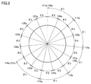
- FIG. 2 is a diagram illustrating an arrangement of cutting edges of the cutting tool according to the present embodiment.
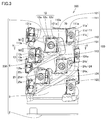
- FIG. 3 is a schematic plan view illustrating the configuration of the cutting tool according to the present embodiment.
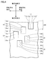
- FIG. 4 is a schematic diagram showing a pocket provided on the outer peripheral surface of the body, with the axial direction as the vertical axis and the rotation direction as the horizontal axis.
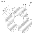
- FIG. 5 is a schematic sectional view taken along line VV of FIG.
- FIG. 6 is an enlarged schematic diagram of a region VI in FIG.
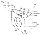
- FIG. 7 is a schematic perspective view showing the configuration of the cutting insert of the cutting tool according to the present embodiment.
- FIG. 1 is a schematic perspective view illustrating a configuration of a cutting tool according to the present embodiment.
- FIG. 2 is a diagram illustrating an arrangement of cutting edges of the cutting tool according to the present embodiment.
- FIG. 3 is a schematic plan view
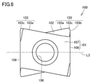
- FIG. 8 is a schematic front view showing the configuration of the cutting insert of the cutting tool according to the present embodiment.
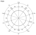
- FIG. 9 is a diagram showing an arrangement of cutting blades in a modified example of the cutting tool according to the present embodiment.
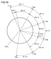
- FIG. 10 is a diagram showing the arrangement of the cutting blades of the cutting tool according to Sample 2.
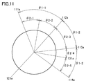
- FIG. 11 is a diagram illustrating the arrangement of the cutting blades of the cutting tool according to Sample 3.
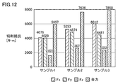
- FIG. 12 is a diagram showing cutting forces of the end mills according to Samples 1 to 3.
- FIG. 13 is a diagram showing the relationship between the height position of the wall surface of the work material processed using the end mills of Samples 1 to 3 and the amount of displacement.
- Patent Document 1 Japanese Patent Application Publication No. 2005-535461
- Patent Document 2 Japanese Patent Application Publication No. 2011-513074
- An object of the present disclosure is to provide a cutting tool capable of improving the chip discharging performance.
- defects of the present disclosure According to the present disclosure, it is possible to provide a cutting tool capable of improving chip discharging performance.
- the cutting tool 300 is a cutting tool 300 that is configured to be rotatable about an axis C, and includes a body 200, a first cutting insert 111, a second cutting insert 112, and a third cutting insert 112. And a cutting insert 113.
- the body 200 has a distal end surface 1 and an outer peripheral surface 3 which is continuous with the distal end surface 1 and in which a first pocket 11, a second pocket 12, and a third pocket 13 are formed.
- the first cutting insert 111 is attached to the first pocket 11.
- the second cutting insert 112 is attached to the second pocket 12.
- the third cutting insert 113 is attached to the third pocket 13.
- the first pocket 11 has a first seating surface 11a located rearward in the rotation direction with respect to the first cutting insert 111, a second seating surface 11c located axially rearward with respect to the first cutting insert 111, and a distal end surface. 1, a third seating surface 11b continuous with each of the first seating surface 11a and the second seating surface 11c, and a first chip discharge groove 11d located forward with respect to the first cutting insert 111 in the rotation direction. .
- the second pocket 12 has a fourth seating surface 12a located rearward in the rotation direction with respect to each of the second cutting insert 112 and the first seating surface 11a, and a second cutting insert 112 and each of the second seating surface 11c.
- the third pocket 13 is axially forward with respect to the third cutting insert 113 and the fourth seating surface 12a, a seventh seating surface 13 a with respect to each of the third cutting insert 113 and the fourth seating surface 12 a, and with respect to the third cutting insert 113.
- An eighth seat surface 13c positioned axially rearward with respect to the fifth seat surface 12c, a ninth seat surface 13b connected to each of the seventh seat surface 13a and the eighth seat surface 13c, and a third cutting insert 113 And a third chip discharge groove 13d which is located forward in the rotation direction and communicates with the second chip discharge groove 12d.
- an angle between a straight line along the sixth seating surface 12b and a tangent of the second chip discharge groove 12d at the boundary between the outer peripheral surface 3 and the second chip discharge groove 12d is 90. Greater than °.
- the chip of the work material cut by the second cutting insert 112 once enters the second chip discharge groove 12d, and then moves along the wall surface constituting the second chip discharge groove 12d, and finally moves to the second chip discharge groove 12d.
- the chips are discharged from the two chip discharge grooves 12d. If the angle between the outer peripheral surface 3 of the body 200 and the tangent to the second chip discharge groove 12d is small, the chips are less likely to be discharged from the second chip discharge groove 12d, and as a result, the chips are stuck in the second chip discharge groove 12d. I will.
- the cutting tool 300 in the cross section perpendicular to the axis C, the second line at the boundary between the outer peripheral surface 3 and the second chip discharge groove 12d and the straight line along the sixth seating surface 12b.
- the angle formed by the tangent to the chip discharge groove 12d is greater than 90 °.
- the first cutting insert 111 has a first cutting edge 111a.
- the second cutting insert 112 has a second cutting edge 112a.
- the third cutting insert 113 has a third cutting edge 113a. When viewed from the direction along the axis C, the angle formed by the first cutting edge 111a and the second cutting edge 112a may be equal to the angle formed by the second cutting edge 112a and the third cutting edge 113a.
- the cutting blades there are an equal division arrangement in which the intervals between the cutting blades are equal when viewed from the axial direction, and an unequal division arrangement in which the intervals between the cutting edges are different.
- the load increases at the portion where the cutting blades overlap in the rotation direction, and the cutting resistance increases.
- the cutting tool 300 vibrates during machining, the accuracy of the machined surface of the work material deteriorates.
- the angle formed by the first cutting edge 111a and the second cutting edge 112a when viewed from the direction along the axis C is the second cutting edge 112a and the third cutting edge 113a.
- the angle formed by the first cutting edge 111a and the second cutting edge 112a is 15 ° or more and 180 ° or less when viewed from the direction along the axis C. Is also good.
- the outer peripheral surface 3 is separated from each of the first pocket 11, the second pocket 12, and the third pocket 13 and the first pocket 11.
- a fourth pocket 24 is located axially rearward with respect to each of the first and second pockets 12, is located rearward in the rotational direction with respect to the first pocket 11, and is located forward in the rotational direction with respect to the second pocket 12. It may be formed.
- a fourth cutting insert 124 attached to the fourth pocket 24 and having a fourth cutting edge 124a may be further provided. When viewed from the direction along the axis C, the angle between the first cutting edge 111a and the fourth cutting edge 124a may be 5 ° or more and 90 ° or less.
- the first cutting edge 111a overlaps the second cutting edge 112a in the direction parallel to the axis C, and The second cutting edge 112a may overlap with the third cutting edge 113a.
- the amount of overlap between the first cutting edge 111a and the second cutting edge 112a may be equal to the amount of overlap between the second cutting edge 112a and the third cutting edge 113a.
- the second chip discharge groove 12 d may include the arcuate portion 7. .
- the chips are discharged from the second chip discharge groove 12d along the arcuate portion 7. Therefore, the chip discharging performance can be further improved.
- the sixth seat in a direction perpendicular to the sixth seat surface 12b.
- the distance between the surface 12b and the bottom 8 of the second chip discharge groove 12d may be 0.5 mm or more and 1.0 mm or less. Thereby, the chip discharging performance can be further improved.
- FIG. 1 is a schematic perspective view showing the configuration of a cutting tool 300 according to the present embodiment.
- a cutting tool 300 according to the present embodiment is, for example, an end mill, and mainly has a body 200, a plurality of cutting inserts 100, and a plurality of fastening screws 70.
- the cutting tool 300 is a rotary cutting tool configured to be rotatable around the axis C.
- the body 200 mainly has a front end surface 1, a rear end surface 2, an outer peripheral surface 3, and an inner peripheral surface 4.
- the rear end surface 2 is a surface attached to the main shaft.
- the rear end face 2 is located on the opposite side of the front end face 1 in the direction along the axis C.
- the outer peripheral surface 3 is continuous with each of the front end surface 1 and the rear end surface 2.
- the inner peripheral surface 4 is continuous with each of the front end surface 1 and the rear end surface 2.
- Each of the outer peripheral surface 3 and the inner peripheral surface 4 surrounds the axis C.
- the outer peripheral surface 3 surrounds the inner peripheral surface 4.
- the inner peripheral surface 4 is constituted by a through hole provided along the axis C.
- a plurality of pockets 11 to 13 are formed on the outer peripheral surface 3.
- One cutting insert 100 is attached to one pocket.
- the cutting insert 100 is attached to a pocket using a fastening screw 70.
- the cutting insert 100 is spirally provided on the outer peripheral surface 3.
- FIG. 2 is a diagram showing an arrangement of cutting blades of the cutting tool 300 according to the present embodiment.
- the number of effective blades of the cutting tool 300 according to the present embodiment is 3, and the number of rows of cutting inserts is 6.
- the cutting inserts 100 fall into three groups.
- One group contains six cutting inserts.
- the six cutting inserts in each of the three groups are arranged along a spiral curve that is spaced apart from each other.
- the blade 111a) is provided at a position of 0 °.
- the cutting edge (second cutting edge 112a) of the second group of cutting inserts (second cutting insert 112) of the first group is provided at a position of 48 °.
- the cutting edge (third cutting edge 113a) of the cutting insert (third cutting insert 113) in the third row of the first group is provided at a position of 96 °.
- the cutting edges of the fourth to sixth rows of the first group of cutting inserts are provided at 144 °, 192 °, and 240 °, respectively.
- the cutting edge (sixth cutting edge 121a) of the cutting insert (sixth cutting insert 121) in the first row of the second group is provided at a position of 240 °.
- the cutting edges (122a to 126a) of the cutting inserts in the second to sixth rows of the second group are provided at positions of 288 °, 336 °, 24 °, 72 ° and 120 °, respectively.
- the cutting edge (seventh cutting edge 131a) of the cutting insert (seventh cutting insert 131) in the first row of the third group is provided at a position of 120 °.
- the cutting edges (132a to 136a) of the cutting inserts in the second to sixth rows of the third group are provided at positions of 168 °, 216 °, 264 °, 312 ° and 0 °, respectively.
- a line segment extending radially from the center of the circle is a line connecting the axis C and the position of the cutting edge.
- the position of the cutting blade is the position of the cutting blade at the forefront in the rotation direction.
- the cutting edge of the cutting tool 300 is, for example, equally divided.
- the angle between two adjacent cutting blades is equal.
- the angle between the first cutting edge 111a and the second cutting edge 112a is equal to the angle between the second cutting edge 112a and the third cutting edge 113a.
- the angle formed by the two cutting edges is an angle formed by a line segment connecting the axis C and one cutting edge and a line segment connecting the axis C and the other cutting edge.
- the angle between the first cutting edge 111a and the second cutting edge 112a and the angle between the second cutting edge 112a and the third cutting edge 113a is 1 ° or less
- the angle between the first cutting edge 111a and the second cutting edge 112a is considered to be equal to the angle between the second cutting edge 112a and the third cutting edge 113a.
- the angle (first angle ⁇ 1) between the first cutting edge 111a and the second cutting edge 112a when viewed from the direction along the axis C is, for example, 48 °.
- the angle (first angle ⁇ 1) formed between the first cutting edge 111a and the second cutting edge 112a is, for example, 15 ° or more and 180 ° or less.
- the cutting edge of the cutting tool 300 according to the present embodiment is preferably equally divided, but may be unequally divided. That is, when viewed from the direction along the axis C, the angle formed by the first cutting edge 111a and the second cutting edge 112a may be different from the angle formed by the second cutting edge 112a and the third cutting edge 113a. .
- FIG. 3 is a schematic plan view showing the configuration of the cutting tool 300 according to the present embodiment.
- FIG. 4 is a schematic diagram showing pockets provided on the outer peripheral surface 3 of the body 200, where the axial direction is the vertical direction and the rotation direction is the horizontal direction.
- the front side in the axial direction is a direction from the rear end face 2 to the front end face 1.
- the term “axially rearward” refers to a direction from the front end surface 1 to the rear end surface 2.
- the rotation direction front is a direction in which the cutting tool 300 rotates.
- the rotation direction rear is the direction opposite to the direction in which the cutting tool 300 rotates.
- a first pocket 11, a second pocket 12, and a third pocket 13 are formed on the outer peripheral surface 3.
- the first cutting insert 111 is attached to the first pocket 11.
- the second cutting insert 112 is attached to the second pocket 12.
- the third cutting insert 113 is attached to the third pocket 13.
- the first pocket 11 has a first seating surface 11a, a second seating surface 11c, a third seating surface 11b, and a first chip discharge groove 11d.
- the first seat surface 11a is located rearward in the rotation direction with respect to the first cutting insert 111.
- the first seat surface 11a is continuous with the distal end surface 1.
- the second seat surface 11c is located axially rearward with respect to the first cutting insert 111.
- the third seat surface 11b is continuous with each of the distal end surface 1, the first seat surface 11a, and the second seat surface 11c.
- the third seat surface 11b extends rearward in the axial direction from the distal end surface 1, extends forward in the rotational direction from the first seat surface 11a, and extends forward in the axial direction from the second seat surface 11c. In the radial direction, the third seating surface 11b is located between the axis C and the outer peripheral surface 3.
- the first chip discharge groove 11d is located forward of the first cutting insert 111 in the rotation direction. The first chip discharge groove 11d is continuous with each of the front end surface 1, the third seating surface 11b, and the second seating surface 11c.
- the second pocket 12 has a fourth seat surface 12a, a fifth seat surface 12c, a sixth seat surface 12b, and a second chip discharge groove 12d.
- the fourth seat surface 12a is located rearward in the rotation direction with respect to each of the second cutting insert 112 and the first seat surface 11a.
- the fifth seat surface 12c is located axially forward with respect to each of the second cutting insert 112 and the second seat surface 11c. In the axial direction, the fifth seat surface 12c is located between the distal end surface 1 and the second seat surface 11c.
- the sixth seating surface 12b is connected to each of the fourth seating surface 12a and the fifth seating surface 12c.
- the sixth seat surface 12b extends rearward in the axial direction from the fifth seat surface 12c, and extends forward from the fourth seat surface 12a in the rotational direction.
- the sixth seating surface 12b is located between the axis C and the outer peripheral surface 3 in the radial direction.
- the second chip discharge groove 12d is located forward of the second cutting insert 112 in the rotation direction.
- the second chip discharge groove 12d is separated from the first chip discharge groove 11d.
- the third pocket 13 has a seventh seat surface 13a, an eighth seat surface 13c, a ninth seat surface 13b, and a third chip discharge groove 13d.
- the seventh seating surface 13a is located rearward in the rotational direction with respect to each of the third cutting insert 113 and the fourth seating surface 12a.
- the eighth seat 13c is located axially forward with respect to the third cutting insert 113 and axially rearward with respect to the fifth seat 12c. In the axial direction, the second seat surface 11c is located between the fifth seat surface 12c and the eighth seat surface 13c.
- the ninth seat surface 13b is continuous with each of the seventh seat surface 13a and the eighth seat surface 13c.
- the ninth seat surface 13b extends rearward in the axial direction from the eighth seat surface 13c, and extends forward in the rotational direction from the seventh seat surface 13a.
- the ninth seat surface 13b is located between the axis C and the outer peripheral surface 3 in the radial direction.
- the third chip discharge groove 13d is located forward of the third cutting insert 113 in the rotation direction.
- the third chip discharge groove 13d communicates with the second chip discharge groove 12d.
- a communication groove 5 is provided on the outer peripheral surface 3.
- the communication groove 5 connects the third chip discharge groove 13d and the second chip discharge groove 12d.
- the communication groove 5 spirally extends from the second chip discharge groove 12d toward the third chip discharge groove 13d.
- the communication groove 5 is located axially rearward with respect to the second cutting insert 112.
- the communication groove 5 may be connected to each of the fourth seat surface 12a, the sixth seat surface 12b, and the ninth seat surface 13b.
- the cutting edges of two adjacent cutting inserts belonging to the same group partially overlap (overlap) in a direction parallel to the axis C.
- the first cutting edge 111a overlaps the second cutting edge 112a in a direction parallel to the axis C.
- the second cutting edge 112a overlaps with the third cutting edge 113a.
- the overlapping amount W1 between the first cutting edge 111a and the second cutting edge 112a may be equal to the overlapping amount W2 between the second cutting edge 112a and the third cutting edge 113a.
- the overlapping amount W1 between the first cutting edge 111a and the second cutting edge 112a is, for example, not less than 0.8 mm and not more than 2.4 mm. In the present specification, when the difference between the overlap amount W1 and the overlap amount W2 is 0.1 mm or less, the overlap amount W1 is considered to be equal to the overlap amount W2.
- a fourth pocket 24 and a fifth pocket 25 are formed on the outer peripheral surface 3.
- a fourth cutting insert 124 is attached to the fourth pocket 24.
- a fifth cutting insert 125 is attached to the fifth pocket 25.
- the group to which the fourth pocket 24 and the fifth pocket 25 belong is different from the group to which each of the first pocket 11, the second pocket 12, and the third pocket 13 belongs.
- the fourth pocket 24 is separated from each of the first pocket 11, the second pocket 12, and the third pocket 13.
- the fifth pocket 25 is separated from each of the first pocket 11, the second pocket 12, and the third pocket 13.
- the fourth pocket 24 is located axially rearward of each of the first pocket 11 and the second pocket 12.
- the fourth pocket 24 is located rearward in the rotational direction with respect to the first pocket 11 and is located forward in the rotational direction with respect to the second pocket 12. In other words, the fourth pocket 24 is located between the first pocket 11 and the second pocket 12 in the rotation direction.
- the fourth pocket 24 has a tenth seat surface 24a, an eleventh seat surface 24c, a twelfth seat surface 24b, and a fourth chip discharge groove 24d.
- the tenth seat surface 24a is located rearward in the rotational direction with respect to each of the fourth cutting insert 124 and the first seat surface 11a.
- the tenth seat surface 24a is located ahead of the fourth seat surface 12a in the rotation direction.
- the eleventh seat surface 24c is located axially forward with respect to the fourth cutting insert 124, and is located axially rearward with respect to each of the second seat surface 11c, the fifth seat surface 12c, and the eighth seat surface 13c. are doing.
- the twelfth seat surface 24b is continuous with each of the tenth seat surface 24a and the eleventh seat surface 24c.
- the twelfth seat surface 24b extends rearward in the axial direction from the eleventh seat surface 24c, and extends forward in the rotational direction from the tenth seat surface 24a. In the radial direction, the twelfth seat surface 24b is located between the axis C and the outer peripheral surface 3.
- the fourth chip discharge groove 24d is located forward of the fourth cutting insert 124 in the rotation direction.
- the fourth chip discharge groove 24d is separated from each of the first chip discharge groove 11d, the second chip discharge groove 12d, and the third chip discharge groove 13d.
- the fifth pocket 25 is located axially rearward of each of the fourth pocket 24 and the third pocket 13.
- the fifth pocket 25 is located rearward in the rotational direction with respect to each of the second pocket 12 and the fourth pocket 24 and is located forward in the rotational direction with respect to the third pocket 13.
- the fifth pocket 25 has a thirteenth seating surface 25a, a fourteenth seating surface 25c, a fifteenth seating surface 25b, and a fifth chip discharge groove 25d.
- the thirteenth seat surface 25a is located rearward in the rotational direction with respect to each of the fifth cutting insert 125 and the tenth seat surface 24a.
- the thirteenth seat surface 25a is located forward of the seventh seat surface 13a in the rotation direction.
- the fourteenth seat surface 25c is located axially forward with respect to the fifth cutting insert 125, and is located axially rearward with respect to each of the fifth seat surface 12c, the eighth seat surface 13c, and the eleventh seat surface 24c. ing.
- the fifteenth seat surface 25b is continuous with the thirteenth seat surface 25a and the fourteenth seat surface 25c.
- the fifteenth seat surface 25b extends rearward in the axial direction from the fourteenth seat surface 25c, and extends forward in the rotational direction from the thirteenth seat surface 25a.
- the fifteenth seat surface 25b is located between the axis C and the outer peripheral surface 3 in the radial direction.
- the fifth chip discharge groove 25d is located forward of the fifth cutting insert 125 in the rotation direction.
- the fifth chip discharge groove 25d is separated from each of the first chip discharge groove 11d, the second chip discharge groove 12d, and the third chip discharge groove 13d.
- the fifth chip discharge groove 25d communicates with the fourth chip discharge groove 24d.
- the fourth cutting insert 124 has a fourth cutting edge 124a.
- the fifth cutting insert 125 has a fifth cutting edge 125a.
- the fourth cutting inserts 124 are arranged in a second group of fourth rows.
- the fifth cutting inserts 125 are arranged in the fifth row of the second group.
- the first cutting inserts 111 are arranged in a first group of first rows.
- the second cutting inserts 112 are arranged in a second row of the first group.
- the third cutting inserts 113 are arranged in the third row of the first group.
- the position of the fourth row of the second group ( 24 °) is located next to the first cutting insert 111 arranged at the position (0 °) of the first row of the first group in the rotation direction.
- the angle (second angle ⁇ 2) formed between the first cutting edge 111a and the fourth cutting edge 124a is, for example, 24 °.
- the angle (second angle ⁇ 2) formed between the first cutting edge 111a and the fourth cutting edge 124a is, for example, not less than 5 ° and not more than 90 °.
- FIG. 5 is a schematic cross-sectional view taken along line VV in FIG.
- the cross section along the line VV is a cross section perpendicular to the axis C and crossing the mounting hole of the second cutting insert 112 in a direction parallel to the axis C.
- FIG. 5 only the body 200 is shown, and the second cutting insert 112 and the fastening screw 70 are omitted.
- FIG. 6 is an enlarged schematic diagram of a region VI in FIG.
- a screw hole 71 is provided in the sixth seating surface 12b.
- the screw hole 71 extends in the radial direction from the sixth seat surface 12b toward the inner peripheral surface 4.
- the screw hole 71 is fastened with the fastening screw 70.
- a straight line (first straight line L1) along the sixth seating surface 12b and a second straight line at the boundary between the outer peripheral surface 3 and the second chip discharge groove 12d is larger than 90 °.
- the third angle ⁇ 3 may be larger than 95 ° or may be larger than 100 °.
- the upper limit of the third angle ⁇ 3 may be, for example, 270 °.
- the second chip discharge groove 12 d may have, for example, a linear portion 6 and an arc-shaped portion 7.
- the straight portion 6 continues to the outer peripheral surface 3.
- the arc-shaped portion 7 is continuous with each of the straight portion 6 and the sixth seating surface 12b.
- the arc-shaped portion 7 is located between the straight portion 6 and the sixth seat surface 12b.
- the straight portion 6 overlaps the second straight line L2.
- the angle (the fourth angle ⁇ 4) between the second straight line L2 and the tangent to the outer peripheral surface 3 may be, for example, smaller than 90 ° or may be 90 ° or more.
- the boundary between the sixth seating surface 12b and the second chip discharge groove 12d (first The distance (first distance A) between the boundary 10) and the boundary (second boundary 9) between the outer peripheral surface 3 and the second chip discharge groove 12d is, for example, 5 mm or more.
- the first distance A may be, for example, 5.5 mm or more, or may be 6 mm or more.
- the arcuate portion 7 is continuous with the sixth seating surface 12 b at the first boundary 10.
- the straight portion 6 continues to the outer peripheral surface 3 at the second boundary.
- the arcuate portion 7 is provided at a position lower than the sixth seating surface 12b.
- the arcuate portion 7 is located between the plane along the sixth seating surface 12b and the inner peripheral surface 4.
- the linear portion 6 is provided at a position higher than the sixth seating surface 12b. In other words, the straight line portion 6 is located between the plane along the sixth seating surface 12b and the second boundary 9.
- the sixth seat surface 12b and the bottom 8 of the second chip discharge groove 12d in a direction perpendicular to the sixth seat surface 12b.
- the distance (second distance B) is, for example, 0.5 mm or more and 1.0 mm or less.
- the second distance B may be, for example, 0.55 mm or more, or 0.6 mm or more.
- the second distance B may be 0.95 mm or less, or may be 0.9 mm or less.
- the bottom 8 of the second chip discharge groove 12d is perpendicular to the sixth seating surface 12b and is the second furthest from the sixth seating surface 12b in the direction from the sixth seating surface 12b toward the inner peripheral surface 4. This is the position of the chip discharge groove 12d.
- FIG. 7 is a schematic perspective view illustrating a configuration of a cutting insert of a cutting tool 300 according to the present embodiment.
- FIG. 8 is a schematic front view showing the configuration of the cutting insert of the cutting tool 300 according to the present embodiment.
- the cutting insert 100 mainly has a rake face 102, a flank 101, a flat face 104, and a mounting hole 106.
- the ridge line between the rake face 102 and the flank 101 constitutes a cutting edge 103.
- the flank 101 has a first outer peripheral area 107 and a second outer peripheral area 108.
- the first outer peripheral region 107 is provided with a mounting hole 106.
- the mounting hole 106 is not provided in the second outer peripheral region 108.
- the flat surface 104 is surrounded by the rake face 102.
- a recess 105 may be provided in the flat surface 104.
- the cutting blade 103 has a main cutting blade 103a, a sub cutting blade 103b, and a corner cutting blade 103c.
- Each of the main cutting edge portion 103a and the sub cutting edge portion 103b is linear.
- the corner cutting edge 103c has a curved shape.
- the main cutting edge 103a is longer than the sub cutting edge 103b.
- the corner cutting edge 103c is located between the main cutting edge 103a and the sub cutting edge 103b.
- the ridge line between each of the pair of first outer peripheral regions 107 and the rake face 102 forms a main cutting edge 103a.
- the ridge line between each of the pair of second outer peripheral regions 108 and the rake face 102 forms a sub cutting edge portion 103b.
- the corner cutting blade 103c When the cutting insert 100 is attached to a pocket of the body 200, the corner cutting blade 103c may be located at the forefront in the rotation direction. From another viewpoint, the cutting insert 100 may be attached to the pocket such that the corner cutting edge portion 103c is positioned forward in the rotation direction with respect to each of the main cutting edge portion 103a and the sub cutting edge portion 103b. .
- each of the pair of main cutting edges 103a may be inclined with respect to a straight line (third straight line L3) perpendicular to the second outer peripheral region 108.
- a straight line third straight line L3 perpendicular to the second outer peripheral region 108.
- each of the pair of main cutting blades 103a may extend so as to cross each other.
- the inclination direction of one main cutting edge 103a with respect to the third straight line may be different from the inclination direction of the other main cutting edge 103a with respect to the third straight line.
- the flat surface 104 contacts the first seat surface 11a, the second outer peripheral region 108 contacts the second seat surface 11c, and the first outer peripheral region 107 3 Contact the seat surface 11b.
- the flat surface 104 contacts the fourth seat surface 12a, the second outer peripheral region 108 contacts the fifth seat surface 12c, and the first outer peripheral region 107 6 Contact the seat surface 12b.
- the flat surface 104 contacts the seventh seat surface 13a, the second outer peripheral region 108 contacts the eighth seat surface 13c, and the first outer peripheral region 107 9 Contact the seat surface 13b.
- FIG. 9 is a diagram showing an arrangement of cutting blades in a modified example of the cutting tool 300 according to the present embodiment.
- the number of effective blades of the cutting tool 300 is two, and the number of rows of cutting inserts is five.
- the cutting edge (first cutting edge 111a) of the cutting insert (first cutting insert 111) in the first row of the first group is 0. ° is provided.
- the cutting edge (second cutting edge 112a) of the second group of cutting inserts (second cutting insert 112) in the first group is provided at a position of 72 °.
- the cutting edge (third cutting edge 113a) of the cutting insert (third cutting insert 113) in the third row of the first group is provided at a position of 144 °.
- the cutting edges of the fourth and fifth rows of cutting inserts of the first group are provided at 216 ° and 288 °, respectively.
- the cutting edge of the cutting insert in the first row of the second group is provided at a position of 180 °.
- the cutting edges of the cutting inserts in the second to fifth rows of the second group are provided at positions of 252 °, 324 °, 36 ° and 108 °, respectively.
- a line segment extending radially from the center (axis C) is a line connecting the axis C and the position of the cutting edge.
- the position of the cutting blade is the position of the cutting blade at the forefront in the rotation direction.
- the cutting edges of the cutting tool 300 are arranged, for example, equally.
- the angle (first angle ⁇ 1) formed between the first cutting edge 111a and the second cutting edge 112a is, for example, 72 °.
- the angle (second angle ⁇ 2) formed by the first cutting edge 111a and the fourth cutting edge 124a is, for example, 36 °.
- the chip of the work material cut by the second cutting insert 112 once enters the second chip discharge groove 12d, and then moves along the wall surface constituting the second chip discharge groove 12d, and finally moves to the second chip discharge groove 12d.
- the chips are discharged from the two chip discharge grooves 12d. If the angle between the outer peripheral surface 3 of the body 200 and the tangent to the second chip discharge groove 12d is small, the chips are less likely to be discharged from the second chip discharge groove 12d, and as a result, the chips are stuck in the second chip discharge groove 12d. I will.
- the cutting tool 300 in the cross section perpendicular to the axis C, the second chip at the boundary between the straight line along the sixth seat surface 12b and the boundary between the outer peripheral surface 3 and the second chip discharge groove 12d.
- the angle formed by the tangent to the discharge groove 12d is greater than 90 °.
- the cutting blades there are an equal division arrangement in which the intervals between the cutting blades are equal when viewed from the axial direction, and an unequal division arrangement in which the intervals between the cutting edges are different.
- the load increases at the portion where the cutting blades overlap in the rotation direction, and the cutting resistance increases.
- the cutting tool 300 vibrates during machining, the accuracy of the machined surface of the work material deteriorates.
- the angle formed by the first cutting edge 111a and the second cutting edge 112a when viewed from the direction along the axis C is the second cutting edge 112a and the third cutting edge 113a.
- the cutting tool 300 when viewed in a cross section perpendicular to the axis C, in the direction parallel to the sixth seat surface 12b, the sixth seat surface 12b and the second chip discharge groove 12d
- the distance between the boundary and the boundary between the outer peripheral surface 3 and the second chip discharge groove 12d may be 5 mm or more.
- the second chip discharge groove 12 d may include the arcuate portion 7 in a cross section perpendicular to the axis C.
- the chips are discharged from the second chip discharge groove 12d along the arcuate portion 7. Therefore, the chip discharging performance can be further improved.
- the cutting tool 300 when viewed in a cross section perpendicular to the axis C, in the direction perpendicular to the sixth seat surface 12b, the sixth seat surface 12b and the second chip discharge groove 12d are formed.
- the distance from the bottom may be 0.5 mm or more and 1.0 mm or less. Thereby, the chip discharging performance can be further improved.
- Sample preparation First, end mills 300 according to samples 1 to 3 were prepared.
- Sample 1 is the end mill 300 (see FIG. 1) according to the present embodiment. Specifically, the arrangement of the cutting blades of the end mill 300 according to the sample 1 is equally divided. The number of effective blades is three. The number of columns is six.
- the first angle ⁇ 1 (see FIG. 2) is 48 °.
- the second angle ⁇ 2 (see FIG. 2) is 24 °.
- the third angle ⁇ 3 (see FIG. 6) is 123 °.
- FIG. 10 is a diagram showing the arrangement of the cutting blades of the cutting tool according to Sample 2. As shown in FIG. 10, the cutting blade arrangement of the end mill 300 according to the sample 2 is unequally divided. The number of effective blades is three.
- FIG. 11 is a diagram illustrating the arrangement of the cutting blades of the cutting tool according to Sample 3. As shown in FIG. 11, the cutting blade arrangement of the end mill 300 according to the sample 3 is unequally divided. The number of effective blades is three. The number of columns is four. The total number of blades is 12.
- the angle ⁇ 1-1 is 60 °.
- the angle ⁇ 1-2 is 45 °.
- the angle ⁇ 2-1 is 35 °.
- the angle ⁇ 2-2 is 25 °.
- the angle ⁇ 2-3 is 45 °.
- the angle ⁇ 2-4 is 15 °.
- the angle ⁇ 2-5 is 30 °.
- End faces and side faces were processed using the end mills 300 according to Samples 1 to 3.
- the diameter of the end mill 300 was 50 mm.
- the equipment was M / C BT-50 vertical type (alloy).
- the cutting speed (Vc) was 200 m / min.
- the feed amount (fz) per blade was 0.2 mm / tooth.
- the axial depth of cut (ap) was 45 mm.
- the radial depth of cut (ae) was 5 mm.
- the refueling method was dry.
- the cutting direction was a down cut.
- the work material was S50C.
- FIG. 12 is a diagram showing the cutting resistance of the end mill 300 according to the samples 1 to 3.
- Fx is the main component.
- Fy is a feed component.
- Fz is the back force.
- the resultant is the square root of the sum of the squares of each component. As shown in FIG. 12, in each of Fx, Fy, Fz, and resultant force, it was confirmed that the cutting force of the end mill 300 according to Sample 1 was smaller than the cutting force of the end mill 300 according to Samples 2 and 3. .
- FIG. 13 is a diagram showing the relationship between the height position of the wall surface of the work material processed using the end mill 300 according to the samples 1 to 3 and the displacement amount.
- the vertical axis and the horizontal axis in FIG. 13 indicate the height position of the wall surface of the work material and the amount of lateral displacement of the wall surface, respectively. The smaller the displacement amount, the higher the accuracy of the wall surface.
- the displacement of the wall surface of the work material processed using the end mill 300 according to the sample 1 is the displacement amount of the wall surface of the work material processed using the end mill 300 according to the samples 2 and 3. Less than. That is, it was confirmed that the wall surface accuracy of the work material processed using the end mill 300 according to the sample 1 was higher than the wall surface accuracy of the work material processed using the end mill 300 according to the samples 2 and 3.
Landscapes
- Engineering & Computer Science (AREA)
- Mechanical Engineering (AREA)
- Milling Processes (AREA)
Abstract
L'invention concerne un outil de coupe, comprenant un corps, une première plaquette de coupe, une deuxième plaquette de coupe et une troisième plaquette de coupe. Le corps comprend une surface d'extrémité distale et une surface périphérique externe. La première plaquette de coupe est fixée à une première poche. La deuxième plaquette de coupe est fixée à une deuxième poche. La troisième plaquette de coupe est fixée à une troisième poche. La première poche comprend une première surface de siège, une deuxième surface de siège, une troisième surface de siège et une première rainure d'élimination de copeaux. La deuxième poche comprend une quatrième surface de siège, une cinquième surface de siège, une sixième surface de siège et une deuxième rainure d'élimination de copeaux. La troisième poche comprend une septième surface de siège, une huitième surface de siège, une neuvième surface de siège et une troisième rainure d'élimination de copeaux. Dans une section transversale perpendiculaire à un axe, l'angle formé par une ligne droite le long de la sixième surface de siège et une tangente de la deuxième rainure d'élimination de copeaux au niveau de la limite entre la surface périphérique externe et la deuxième rainure d'élimination de copeaux est supérieur à 90°.
Priority Applications (4)
| Application Number | Priority Date | Filing Date | Title |
|---|---|---|---|
| JP2020507714A JP6699838B1 (ja) | 2018-09-12 | 2019-09-04 | 切削工具 |
| US16/651,189 US11504780B2 (en) | 2018-09-12 | 2019-09-04 | Cutting tool |
| EP19859424.4A EP3851234B1 (fr) | 2018-09-12 | 2019-09-04 | Outil de coupe |
| CN201980059005.2A CN112703076B (zh) | 2018-09-12 | 2019-09-04 | 切削工具 |
Applications Claiming Priority (2)
| Application Number | Priority Date | Filing Date | Title |
|---|---|---|---|
| JP2018-170323 | 2018-09-12 | ||
| JP2018170323 | 2018-09-12 |
Publications (1)
| Publication Number | Publication Date |
|---|---|
| WO2020054558A1 true WO2020054558A1 (fr) | 2020-03-19 |
Family
ID=69777600
Family Applications (1)
| Application Number | Title | Priority Date | Filing Date |
|---|---|---|---|
| PCT/JP2019/034851 Ceased WO2020054558A1 (fr) | 2018-09-12 | 2019-09-04 | Outil de coupe |
Country Status (5)
| Country | Link |
|---|---|
| US (1) | US11504780B2 (fr) |
| EP (1) | EP3851234B1 (fr) |
| JP (1) | JP6699838B1 (fr) |
| CN (1) | CN112703076B (fr) |
| WO (1) | WO2020054558A1 (fr) |
Families Citing this family (6)
| Publication number | Priority date | Publication date | Assignee | Title |
|---|---|---|---|---|
| CN110494242B (zh) * | 2017-08-09 | 2020-08-25 | Osg株式会社 | 可转位式切削工具 |
| USD910094S1 (en) | 2018-09-11 | 2021-02-09 | Sumitomo Electric Hardmetal Corp. | Cutting tool |
| USD1065274S1 (en) * | 2020-08-24 | 2025-03-04 | Sumitomo Electric Hardmetal Corp. | Pressing tool for cutting tool |
| USD1072005S1 (en) * | 2021-02-03 | 2025-04-22 | Us Synthetic Corporation | Pick |
| US12533737B2 (en) * | 2021-09-03 | 2026-01-27 | Makino Inc. | Method for manufacturing a rotatable tool body to minimize cutting insert runout, a tool body produced therefrom, and a method of using such a tool body |
| USD1121692S1 (en) * | 2025-03-24 | 2026-04-07 | Yih Troun Enterprise Co., Ltd. | Cutter of machine tool |
Citations (11)
| Publication number | Priority date | Publication date | Assignee | Title |
|---|---|---|---|---|
| JPS6029416U (ja) * | 1983-08-05 | 1985-02-27 | ダイジヱット工業株式会社 | スロ−アウェイ式エンドミル用のチップ |
| JPS62168210U (fr) * | 1986-04-17 | 1987-10-26 | ||
| JPH023376Y2 (fr) * | 1985-09-17 | 1990-01-26 | ||
| JP2005535461A (ja) | 2002-05-31 | 2005-11-24 | ケンナメタル インコーポレイテッド | 螺旋状インサート及びカッター本体 |
| US20080050185A1 (en) * | 2006-08-23 | 2008-02-28 | Hermance Machine Company | Helical cutterhead |
| WO2010100953A1 (fr) * | 2009-03-06 | 2010-09-10 | 三菱マテリアル株式会社 | Plaquette de coupe et outil comportant des plaquettes de coupe |
| JP2011020235A (ja) * | 2009-07-17 | 2011-02-03 | Daishowa Seiki Co Ltd | 切削工具 |
| JP2011513074A (ja) | 2008-02-22 | 2011-04-28 | ケンナメタル インコーポレイテッド | ヘリカルフライス |
| WO2013022555A1 (fr) * | 2011-08-10 | 2013-02-14 | TDY Industries, LLC | Insert de coupe et outil de coupe dotés d'arêtes de coupe sinusoïdales et hélicoïdales |
| JP2014083629A (ja) * | 2012-10-23 | 2014-05-12 | Mitsubishi Materials Corp | 刃先交換式切削工具及びその工具本体 |
| JP2018170323A (ja) | 2017-03-29 | 2018-11-01 | Necプラットフォームズ株式会社 | 半田付け装置および電子部品の製造方法 |
Family Cites Families (30)
| Publication number | Priority date | Publication date | Assignee | Title |
|---|---|---|---|---|
| DE1627088A1 (de) * | 1967-09-20 | 1970-04-30 | Hans Heinlein | Walzenfraeser |
| JPS6020816A (ja) * | 1983-07-13 | 1985-02-02 | Toshiba Tungaloy Co Ltd | スロ−アウエイ式のエンドミル |
| US4573831A (en) * | 1983-10-21 | 1986-03-04 | Dijet Industrial Co., Ltd. | Cutter blade |
| US4648755A (en) * | 1985-07-15 | 1987-03-10 | Gte Valeron Corporation | Multiple insert end mill |
| US4790693A (en) * | 1987-02-06 | 1988-12-13 | Ingersoll Cutting Tool Company | Interfitting on-edge inserts for milling cutters |
| US4812087A (en) * | 1987-07-09 | 1989-03-14 | Gte Valenite Corporation | End mill cutting tool and indexable insert therefor |
| DE4137230A1 (de) * | 1991-11-13 | 1993-05-27 | Daimler Benz Ag | Schrupp-schaftfraeser mit runden wendeschneidplatten |
| CA2062213C (fr) * | 1992-03-03 | 1996-07-16 | Alfonso Minicozzi | Plaquette amovible pour outils de deroulage |
| JP3376727B2 (ja) * | 1994-11-11 | 2003-02-10 | 三菱マテリアル株式会社 | スローアウェイ式エンドミル |
| EP0823301A4 (fr) * | 1996-02-26 | 1998-05-20 | Kanefusa Kabusiki Kaisha | Fraise en bout |
| US5913644A (en) * | 1998-04-20 | 1999-06-22 | Kennametal Inc. | Helical mill having multiple flutes with differing rake angles |
| SE516252C2 (sv) * | 2000-04-28 | 2001-12-10 | Sandvik Ab | Fräsverktyg innefattande en roterbar kropp samt tangentiellt åtskilda skärorgan |
| JP3775321B2 (ja) * | 2002-03-20 | 2006-05-17 | 三菱マテリアル株式会社 | スローアウェイチップおよびスローアウェイ式切削工具 |
| US6811359B2 (en) * | 2002-05-31 | 2004-11-02 | Kennametal Inc. | True helical cutter system |
| US7399146B2 (en) * | 2003-09-29 | 2008-07-15 | Kennametal Inc. | Rotary cutting tool having irregular insert orientation |
| US7708038B1 (en) * | 2006-11-27 | 2010-05-04 | Stewart John S | Substantially helical, stepped blade row cutterhead having removable blade units |
| US8454284B2 (en) * | 2008-12-01 | 2013-06-04 | Kennametal Inc. | Milling cutter coupling system |
| DE102009005634B4 (de) * | 2009-01-21 | 2012-03-01 | Leitz Gmbh & Co. Kg | Fräswerkzeug und Schneidelement für ein Fräswerkzeug |
| US8647026B2 (en) * | 2011-11-23 | 2014-02-11 | Kennametal Inc. | Cutting tool with pocket feature for reducing stress |
| EP2799173B1 (fr) * | 2013-05-04 | 2020-02-12 | Ledermann GmbH & Co. KG | Tête de mesure et plaque de coupe |
| WO2014207747A2 (fr) * | 2013-06-27 | 2014-12-31 | No Screw Ltd. | Pièce rapportée de coupe à refroidissement interne |
| JP5991563B2 (ja) * | 2013-12-25 | 2016-09-14 | 株式会社タンガロイ | 刃先交換式回転切削工具及び工具ボデー |
| US9387537B2 (en) * | 2014-03-28 | 2016-07-12 | Kennametal Inc. | Wedge clamp with fluid port |
| US9764394B2 (en) * | 2014-04-07 | 2017-09-19 | Kennametal Inc. | Rotary cutting tool with increased stiffness and method of assembling same |
| DE202015101167U1 (de) * | 2015-03-09 | 2015-03-16 | Albert Knebel Holding Gmbh | Fräswerkzeug mit am Umfang angeordneter Schneide |
| JP6587090B2 (ja) | 2015-03-30 | 2019-10-09 | 国立大学法人名古屋大学 | 転削工具 |
| US10556278B2 (en) * | 2016-08-16 | 2020-02-11 | Kennametal Inc. | Tool body for a shell end mill and cutting tool |
| US10201862B2 (en) * | 2016-09-07 | 2019-02-12 | Iscar, Ltd. | Cutting tool having a coolant chamber with an integrally formed coolant deflection portion and tool body |
| US10525538B2 (en) * | 2016-11-15 | 2020-01-07 | Sumitomo Electric Hardmetal Corp. | Cutting tool |
| US10549352B1 (en) * | 2018-08-07 | 2020-02-04 | Kennametal Inc. | Indexable tangential cutting inserts and cutting tool holders |
-
2019
- 2019-09-04 CN CN201980059005.2A patent/CN112703076B/zh active Active
- 2019-09-04 US US16/651,189 patent/US11504780B2/en active Active
- 2019-09-04 JP JP2020507714A patent/JP6699838B1/ja active Active
- 2019-09-04 EP EP19859424.4A patent/EP3851234B1/fr active Active
- 2019-09-04 WO PCT/JP2019/034851 patent/WO2020054558A1/fr not_active Ceased
Patent Citations (11)
| Publication number | Priority date | Publication date | Assignee | Title |
|---|---|---|---|---|
| JPS6029416U (ja) * | 1983-08-05 | 1985-02-27 | ダイジヱット工業株式会社 | スロ−アウェイ式エンドミル用のチップ |
| JPH023376Y2 (fr) * | 1985-09-17 | 1990-01-26 | ||
| JPS62168210U (fr) * | 1986-04-17 | 1987-10-26 | ||
| JP2005535461A (ja) | 2002-05-31 | 2005-11-24 | ケンナメタル インコーポレイテッド | 螺旋状インサート及びカッター本体 |
| US20080050185A1 (en) * | 2006-08-23 | 2008-02-28 | Hermance Machine Company | Helical cutterhead |
| JP2011513074A (ja) | 2008-02-22 | 2011-04-28 | ケンナメタル インコーポレイテッド | ヘリカルフライス |
| WO2010100953A1 (fr) * | 2009-03-06 | 2010-09-10 | 三菱マテリアル株式会社 | Plaquette de coupe et outil comportant des plaquettes de coupe |
| JP2011020235A (ja) * | 2009-07-17 | 2011-02-03 | Daishowa Seiki Co Ltd | 切削工具 |
| WO2013022555A1 (fr) * | 2011-08-10 | 2013-02-14 | TDY Industries, LLC | Insert de coupe et outil de coupe dotés d'arêtes de coupe sinusoïdales et hélicoïdales |
| JP2014083629A (ja) * | 2012-10-23 | 2014-05-12 | Mitsubishi Materials Corp | 刃先交換式切削工具及びその工具本体 |
| JP2018170323A (ja) | 2017-03-29 | 2018-11-01 | Necプラットフォームズ株式会社 | 半田付け装置および電子部品の製造方法 |
Also Published As
| Publication number | Publication date |
|---|---|
| EP3851234A4 (fr) | 2022-06-29 |
| EP3851234B1 (fr) | 2023-10-04 |
| JP6699838B1 (ja) | 2020-05-27 |
| JPWO2020054558A1 (ja) | 2020-10-22 |
| CN112703076A (zh) | 2021-04-23 |
| US20200269325A1 (en) | 2020-08-27 |
| US11504780B2 (en) | 2022-11-22 |
| EP3851234A1 (fr) | 2021-07-21 |
| CN112703076B (zh) | 2023-06-06 |
Similar Documents
| Publication | Publication Date | Title |
|---|---|---|
| WO2020054558A1 (fr) | Outil de coupe | |
| CN104023886B (zh) | 球头立铣刀 | |
| KR101173843B1 (ko) | 절삭 인서트 및 이것을 이용한 인덱서블 치절 공구 | |
| JP5108106B2 (ja) | スローアウェイ式切削回転工具 | |
| US9381582B2 (en) | Milling tool with recessed cutting edge | |
| US8277152B2 (en) | End mill | |
| JP5198579B2 (ja) | スローアウェイ式切削回転工具 | |
| KR20110036532A (ko) | 와이퍼 날을 갖는 절삭 인서트 | |
| JP2016190299A (ja) | 総形エンドミル | |
| KR20050007568A (ko) | 드릴링 공구 및 인덱서블 드릴 비트 | |
| WO2014069265A1 (fr) | Fraise en bout ayant des trous de fluide de refroidissement | |
| KR20170066368A (ko) | 라디우스 엔드 밀 | |
| JPWO2018168341A1 (ja) | ボールエンドミル | |
| JP7527796B2 (ja) | 多刃ボールエンドミル及び多刃ボールエンドミルの加工方法 | |
| JP4631328B2 (ja) | 縦送り加工用エンドミル | |
| JP5470796B2 (ja) | 総形カッタ | |
| JP2013202748A (ja) | エンドミル | |
| JP2004276142A (ja) | エンドミル | |
| JPH06335814A (ja) | エンドミル | |
| JPH067855Y2 (ja) | エンドミル | |
| JP7806573B2 (ja) | エンドミル | |
| JP2022016103A (ja) | ボールエンドミル | |
| JP2012206245A (ja) | エンドミル | |
| JP7564493B2 (ja) | エンドミル | |
| JP4870498B2 (ja) | 回転切削工具 |
Legal Events
| Date | Code | Title | Description |
|---|---|---|---|
| ENP | Entry into the national phase |
Ref document number: 2020507714 Country of ref document: JP Kind code of ref document: A |
|
| 121 | Ep: the epo has been informed by wipo that ep was designated in this application |
Ref document number: 19859424 Country of ref document: EP Kind code of ref document: A1 |
|
| NENP | Non-entry into the national phase |
Ref country code: DE |
|
| ENP | Entry into the national phase |
Ref document number: 2019859424 Country of ref document: EP Effective date: 20210412 |