WO2020054585A1 - Dispositif de traitement d'informations, procédé de traitement d'informations et programme - Google Patents
Dispositif de traitement d'informations, procédé de traitement d'informations et programme Download PDFInfo
- Publication number
- WO2020054585A1 WO2020054585A1 PCT/JP2019/035078 JP2019035078W WO2020054585A1 WO 2020054585 A1 WO2020054585 A1 WO 2020054585A1 JP 2019035078 W JP2019035078 W JP 2019035078W WO 2020054585 A1 WO2020054585 A1 WO 2020054585A1
- Authority
- WO
- WIPO (PCT)
- Prior art keywords
- space
- information
- user
- information processing
- rotation
- Prior art date
- Legal status (The legal status is an assumption and is not a legal conclusion. Google has not performed a legal analysis and makes no representation as to the accuracy of the status listed.)
- Ceased
Links
Images


Classifications
-
- G—PHYSICS
- G06—COMPUTING OR CALCULATING; COUNTING
- G06F—ELECTRIC DIGITAL DATA PROCESSING
- G06F3/00—Input arrangements for transferring data to be processed into a form capable of being handled by the computer; Output arrangements for transferring data from processing unit to output unit, e.g. interface arrangements
- G06F3/01—Input arrangements or combined input and output arrangements for interaction between user and computer
-
- G—PHYSICS
- G06—COMPUTING OR CALCULATING; COUNTING
- G06F—ELECTRIC DIGITAL DATA PROCESSING
- G06F3/00—Input arrangements for transferring data to be processed into a form capable of being handled by the computer; Output arrangements for transferring data from processing unit to output unit, e.g. interface arrangements
- G06F3/01—Input arrangements or combined input and output arrangements for interaction between user and computer
- G06F3/03—Arrangements for converting the position or the displacement of a member into a coded form
- G06F3/033—Pointing devices displaced or positioned by the user, e.g. mice, trackballs, pens or joysticks; Accessories therefor
- G06F3/038—Control and interface arrangements therefor, e.g. drivers or device-embedded control circuitry
-
- G—PHYSICS
- G06—COMPUTING OR CALCULATING; COUNTING
- G06T—IMAGE DATA PROCESSING OR GENERATION, IN GENERAL
- G06T19/00—Manipulating three-dimensional [3D] models or images for computer graphics
Definitions
- the present disclosure relates to an information processing device, an information processing method, and a program.
- VR Virtual Reality
- VR technology is utilized in various situations, such as supporting communication between users in remote locations and providing highly immersive visual content.
- VR technology is a technology that allows a user to perceive a virtual space as if it were a real space.
- a technology has been developed in which a celestial sphere image (a 360-degree panoramic image in all directions, up, down, left, and right) is used as a virtual space.
- Patent Literature 1 discloses a technique in which an omnidirectional image is generated based on a captured image captured by an imaging device, and an area corresponding to the head direction of the user in the generated omnidirectional image is displayed. Have been. According to this technique, when the user changes the head direction, the changed head direction area of the celestial sphere image is displayed, so that the user is as if in the real space where the image was taken. You can get a feeling.
- the present disclosure provides a mechanism that can prevent a user from shifting the spatial recognition between the virtual space and the real space.
- a first reference direction in the first space and a second reference in the second space when the coordinate system of the first space is associated with the coordinate system of the second space A generation unit configured to generate rotation information for rotating the second space based on angle information indicating an angle between the second space and a direction related to a line of sight of a user in the first space.
- a computer is configured to associate a first reference direction in the first space with a coordinate system in the first space and a coordinate system in the second space with the second space.
- a generating unit that generates rotation information for rotating the second space based on angle information indicating an angle between the second space and the second reference direction and a direction related to a line of sight of a user in the first space.
- a program for functioning as a program is provided.
- FIG. 1 is a diagram for describing an outline of an information processing device according to an embodiment of the present disclosure.
- FIG. 3 is a diagram for describing a second calibration process according to the embodiment.
- FIG. 3 is a block diagram illustrating an example of a logical configuration of the information processing apparatus according to the embodiment. It is a figure for explaining generation processing of rotation information according to head direction S concerning the embodiment. It is a figure showing an example of a locus of a position of a head direction in virtual space when rotation of virtual space based on rotation information concerning the embodiment is performed. It is a figure showing an example of a screen displayed by HMD concerning the embodiment. It is a flow chart which shows an example of the flow of rotation correction processing performed by HMD concerning the embodiment.
- FIG. 1 is a diagram for describing an outline of an information processing device according to an embodiment of the present disclosure.
- FIG. 3 is a diagram for describing a second calibration process according to the embodiment.
- FIG. 3 is a block diagram illustrating an example of a logical
- FIG. 11 is a diagram for describing a second calibration process according to a first modification.
- FIG. 11 is a diagram for describing a rotation correction process according to a second modification.
- 15 is a graph showing the amount of change in the height of the camera viewpoint when the camera viewpoint is moved up and down and when the virtual space is rotated in the second modification.
- FIG. 2 is a block diagram illustrating an example of a hardware configuration of the information processing apparatus according to the embodiment.
- FIG. 1 is a diagram for describing an outline of an information processing apparatus according to an embodiment of the present disclosure.
- the information processing device 1 is an HMD (Head Mounted Display).
- a user in the real space 10 wears the HMD 1 and appreciates VR content relating to the virtual space 20 (corresponding to the second space).
- the VR content includes image data of the virtual space 20.
- the VR content may include audio data of the virtual space 20.
- the virtual space 20 is a spherical image.
- the virtual space 20 may be a semi-celestial sphere image (a panoramic image of 90 degrees left and right 360 degrees) or an image having any other imaging range.
- $ HMD1 is an example of an information processing device that reproduces VR content.
- the HMD 1 is mounted on the user's head such that a display unit capable of displaying an image is located in front of the user's eyes. Then, the HMD 1 reproduces (for example, displays and / or outputs audio) the VR content.
- the information processing device that reproduces the VR content may be realized by a smartphone, a tablet terminal, a projector, or the like, in addition to the HMD 1.
- X 1 axis is defined by Y 1 axis and a Z 1 axis.
- the X 1 axis and the Y 1 axis are coordinate axes that define the horizontal plane 11 of the real space 10.
- Y 1 axis is a coordinate axis that matches the horizontal component of the first reference direction
- X 1 axis is a coordinate axis orthogonal to the Y 1 axis.
- Z 1 axis is a coordinate axis coincides with the vertical direction in the real space 10.
- the first reference direction is a direction that is easy for the user to see, and is typically the direction of the horizontal plane 11 of the real space 10.
- the origin of the real space 10 is the viewpoint or head of the user
- the horizontal plane 11 of the real space 10 is a horizontal plane passing through the origin of the real space 10.
- the first reference direction is a direction from the origin of the real space 10 to the other end.
- Coordinate system of the virtual space 20 X 2 axis, defined by Y 2 axis, and Z 2 axes.
- X 2 axis and Y 2 axis is a coordinate axis defining the horizontal surface 21 of the virtual space 20.
- Y 2 axis is a coordinate axis that matches the horizontal component of the second reference direction
- X 2 axis is a coordinate axis perpendicular to the Y 2 axis.
- Z 2 axes are coordinate axes coincides with the vertical direction of the virtual space 20.
- the second reference direction is a direction of a specific position (hereinafter, also referred to as a target position) in the virtual space 20.
- the target position is typically a position in the virtual space 20 that the user wants to see or wants to show to the user.
- the horizontal plane 21 of the virtual space 20 is a horizontal plane originating from the camera position of the VR content.
- the origin of the virtual space 20 is the camera position of the VR content, and the horizontal plane 21 of the virtual space 20 is a horizontal plane passing through the origin of the virtual space 20.
- the second reference direction is a direction from the origin of the virtual space 20 to the other end.
- the HMD 1 first performs a calibration process for determining the attitude of the virtual space 20 with respect to the real space 10.
- the calibration process will be described.
- the left diagram of FIG. 1 shows the real space 10 and the virtual space 20 in the initial state after the first calibration process.
- the initial state refers to a state in which the head direction matches the first reference direction.
- a state other than the initial state that is, a state in which the head direction does not match the first reference direction is also referred to as a changed state.
- the right diagram of FIG. 1 shows a state of the real space 10 and the virtual space 20 in a changed state after the first calibration processing.
- the first calibration process X 1 axis and the X 2 axis coincides, Y 1 axis and a Y 2 axis coincides, and Z 2 axis and Z 2 axes Matches.
- the space recognition of the real space 10 perceived by the user based on the direction of gravity (recognition of the horizontal plane 11 and the vertical direction of the real space 10) and the virtual space 20 perceived based on the image of the virtual space 20 viewed by the user.
- Space recognition (recognition of the horizontal plane 21 and the vertical direction of the virtual space 20) coincides with each other. Therefore, the user can appreciate the virtual space 20 without feeling uncomfortable.
- $ HMD1 displays VR content.
- the HMD 1 displays an image of the position V in the direction S with respect to the user's line of sight (for example, an image of a predetermined area centered on the position V) in the virtual space 20, as shown in the left diagram of FIG. .
- the direction S regarding the user's line of sight may be the user's line of sight or the head direction of the user.
- the line-of-sight direction means the direction of the eyeball (for example, the direction of the gazing point).
- the head direction means the direction of the face.
- the HMD 1 displays an image of the position V in the user's head direction S in the virtual space 20.
- the HMD 1 displays an image of the position V in the head direction S after the change in the virtual space 20. In this way, the user can enjoy the experience of looking around 360 degrees in VR content.
- the pitch angle in the first reference direction that is, the direction that is easy for the user to see
- the pitch angle in the second reference direction that is, the direction of the target position
- the user turns the head direction S in a direction that is easy to see (for example, without tilting the head up and down), and also includes a region including the target position (for example, a predetermined region centered on the target position; This is because it is possible to appreciate the image of the image.
- the pitch angle is a vertical rotation angle with respect to the horizontal plane 11 of the real space 10. For example, if the horizontal component of the head direction S of the user matches with the Y 1 axis, the pitch axis coincides with X 1, the pitch angle is the rotation angle around the X 1 axis.
- the HMD 1 when the first calibration process is performed, the pitch angle in the first reference direction may not match the pitch angle in the second reference direction. Therefore, the HMD 1 according to the present embodiment performs the second calibration process.
- the second calibration process will be described with reference to FIG.
- FIG. 2 is a diagram for explaining the second calibration process according to the present embodiment.
- the left diagram of FIG. 2 shows the state of the real space 10 and the virtual space 20 in the initial state after the first calibration process
- the right diagram of FIG. 2 shows the initial state after the second calibration process.
- 1 shows a state of a real space 10 and a virtual space 20.
- the horizontal plane 11 of the real space 10 and the horizontal plane 21 of the virtual space 20 match by the first calibration process.
- the direction of the target region T is shifted upward from the horizontal plane 11 of the real space 10 (that is, the pitch angle ⁇ 0). Therefore, the user rotates the head direction S around the pitch axis to display the image of the target region T on the HMD 1, that is, in order to match the position V with the target region T.
- the user is obliged to tilt his head upward to appreciate the image of the target area T. Considering that the viewing time of VR content can be long, the burden cannot be ignored.
- the virtual space 20 is rotated in advance so that the first reference direction matches the second reference direction.
- a calibration process is also referred to as a second calibration process.
- the horizontal plane 11 of the real space 10 and the horizontal plane 21 of the virtual space 20 are shifted by the second calibration process.
- the direction of the target area T is located on the horizontal plane 11 of the real space 10 (that is, the pitch angle ⁇ 0), and the position of the head direction S in the initial state.
- V matches the target area T. Therefore, the user can display the image of the target area T on the HMD 1 without rotating the head direction S about the pitch axis. That is, the user can view the image of the target area T without tilting the head up and down. Therefore, the burden imposed on the user when the first calibration process is performed is eliminated.
- the same rotation as the rotation of the virtual space 20 performed in the second calibration process is performed with reference to the head direction S of the user. Accordingly, the virtual space 20 always tilts with respect to the head direction S, and when the user rotates the head direction S along the horizontal plane 11 of the real space 10, the trajectory parallel to the horizontal plane 21 of the virtual space 20 The image in the upper area is displayed. In this way, the user is prevented from misaligning the space between the virtual space and the real space.
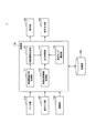
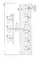
- FIG. 3 is a block diagram illustrating an example of a logical configuration of the information processing device 1 (for example, the HMD 1) according to the present embodiment.
- the HMD 1 includes a sensor unit 110, an operation input unit 120, a communication unit 130, a display unit 140, a sound output unit 150, a storage unit 160, and a control unit 170.
- the sensor unit 110 has a function of detecting various information related to the HMD 1 or the user.
- the sensor unit 110 includes an imaging unit for imaging the eyes of the user.
- the imaging unit includes a lens system including an imaging lens, an aperture, a zoom lens, and a focus lens, a driving system that performs a focus operation and a zoom operation on the lens system, and a photoelectric conversion of imaging light obtained by the lens system.
- a solid-state imaging device array for generating an imaging signal. The imaging unit captures an image of the user's eye, and outputs data of the captured image to the control unit 170.
- the HMD 1 includes a gyro sensor.
- the gyro sensor detects the angular velocity of the HMD 1.
- the gyro sensor includes a vibrator such as a piezoelectric vibrator or a silicon vibrator, and detects an angular velocity based on Coriolis force applied to the vibrating vibrator.
- the gyro sensor outputs information indicating the detected angular velocity to the control unit 170.
- the HMD 1 includes an acceleration sensor.
- the acceleration sensor detects the acceleration of HMD1.
- the acceleration sensor detects acceleration by an arbitrary detection method such as an optical method or a semiconductor method.
- the number of axes for detecting acceleration is arbitrary, and may be, for example, three axes.
- the acceleration sensor outputs information indicating the detected acceleration to the control unit 170.
- the HMD 1 includes a direction sensor.
- the direction sensor has a function of detecting the direction of the HMD 1.
- the azimuth sensor includes a terrestrial magnetism sensor, and based on information indicating the azimuth detected by the terrestrial magnetism sensor and the installation orientation of the terrestrial magnetism sensor in the HMD 1, determines the direction in which the HMD 1 faces (for example, the head direction S described above). To detect.
- the HMD 1 outputs information indicating the detected orientation to the control unit 170.
- Operation input unit 120 has a function of receiving an operation input from a user. For example, the operation input unit 120 receives an input of a calibration start instruction and an operation mode selection instruction from a user. The operation input unit 120 outputs operation input information from the user to the control unit 170.
- the communication unit 130 is an interface that transmits and receives information to and from other devices.
- the communication unit 130 communicates in accordance with any wired or wireless communication standard such as LAN (Local Area Network), wireless LAN, Wi-Fi (registered trademark), Bluetooth (registered trademark), or NFC (Near Field Communication). I do.
- LAN Local Area Network
- Wi-Fi registered trademark
- Bluetooth registered trademark
- NFC Near Field Communication
- the display unit 140 has a function of displaying an image.
- the display unit 140 displays an image of the virtual space 20 based on the control of the output control unit 177.
- Audio output unit 150 The sound output unit 150 has a function of outputting sound. The sound output unit 150 outputs the sound of the virtual space 20 based on the control of the output control unit 177.
- Storage unit 160 has a function of temporarily or non-temporarily storing information for the operation of the HMD 1.
- the storage unit 160 stores, for example, VR content, and stores angle information generated by the rotation information generation unit 175 each time the second calibration process is executed.
- Control unit 170 has a function of controlling the overall operation in the HMD 1. As illustrated in FIG. 3, the control unit 170 includes a gaze-related direction acquisition unit 171, a virtual space information acquisition unit 173, a rotation information generation unit 175, an output control unit 177, and an operation mode selection unit 179.
- the gaze-related direction acquisition unit 171 has a function of acquiring a direction related to the gaze of the user in the real space 10.
- the gaze-related direction acquisition unit 171 outputs the information indicating the acquired direction related to the gaze of the user to the rotation information generation unit 175.
- the virtual space information acquisition unit 173 has a function of acquiring virtual space information that is information on the virtual space 20.
- the virtual space information acquisition unit 173 outputs the acquired virtual space information to the output control unit 177.
- the rotation information generation unit 175 functions as a generation unit that generates rotation information that is information for rotating the virtual space 20.
- the rotation information generation unit 175 outputs the generated rotation information to the output control unit 177.
- the output control unit 177 has a function of causing the output device to output output information to the user based on the virtual space information and the rotation information. For example, the output control unit 177 generates output control information based on virtual space information and rotation information. Next, the output control unit 177 outputs the output control information to the display unit 140 and the audio output unit 150, causes the image of the virtual space 20 to be output to the display unit 140, and outputs the audio of the virtual space 20 to the audio output unit 150. Let it.
- the operation mode selection unit 179 has a function of selecting an operation mode of the output control unit 177.
- the operation mode selection unit 179 outputs information indicating the selected operation mode to the output control unit 177, and switches the operation mode of the output control unit 177.
- the gaze-related direction acquisition unit 171 acquires a direction related to the gaze of the user in the real space 10.
- the direction related to the user's line of sight is described as the head direction, but the direction related to the user's line of sight may be the line of sight.
- the gaze-related direction acquisition unit 171 calculates the position and orientation of the user's head based on the detection results of the gyro sensor, the acceleration sensor, and / or the direction sensor included in the sensor unit 110, and calculates the user's head.
- the head direction of the user is calculated based on the posture of the user.
- the gaze-related direction acquisition unit 171 performs image recognition processing on an image of the user's eye captured by the imaging unit included in the sensor unit 110, and performs the image recognition result and the position and orientation of the user's head. Is calculated based on the calculation result.
- the virtual space information acquisition unit 173 acquires virtual space information.
- the virtual space information corresponds to the VR content described above.
- the virtual space information includes image data of the virtual space 20 and / or audio data of the virtual space 20.
- the virtual space information acquisition unit 173 acquires VR content by receiving VR content via the communication unit 130 or reading VR content stored in the storage unit 160.
- the first reference direction is a direction that is easy for the user to see as described above, and is typically the direction of the horizontal plane 11 of the real space 10.
- the first reference direction may be set as a horizontal component of the head direction S at the start of the second calibration process. Further, the first reference direction may be set as a horizontal component of the head direction S at the start of using the HMD 1 or as a horizontal component of the head direction S when the user faces the front.
- the first reference direction may be set in advance as information accompanying the VR content.
- the second reference direction is a direction of a specific position (hereinafter, also referred to as a target position) in the virtual space 20 as described above.
- the target position is typically a position in the virtual space 20 that the user wants to see or wants to show to the user.
- the target position may be a position of an object such as a person's face or a building, or may be a position other than the object such as a single point in the sky.
- the target position may be set in advance as information accompanying the VR content.
- the target position may be set by the user.
- the target position may be set based on the head direction or the line-of-sight direction of the user.
- a second calibration process in which the position of the object is a specific position is executed. Can be done. At that time, the position of the head direction or the line of sight on the object may be set as the specific position, or the center position of the object may be set as the specific position. As an example of the latter, when the user gazes at a human eye in the virtual space 20, the center position of the human face may be set as the target position. From these, the user can arrange any position in the virtual space 20 in a direction that makes it easy to see.
- the rotation information generating unit 175 obtains angle information for the second calibration process.
- the second calibration processing includes obtaining angle information and rotating the virtual space 20 based on the angle information.
- the rotation of the virtual space 20 based on the angle information is realized by a rotation correction process described later.
- the rotation information generation unit 175 determines the distance between the first reference direction in the real space 10 and the second reference direction in the virtual space 20 when the coordinate system of the real space 10 is associated with the coordinate system of the virtual space 20. Obtain angle information indicating the angle of.
- associating the coordinate system of the real space 10 with the coordinate system of the virtual space 20 means that the origin of the real space 10 and the origin of the virtual space 20 coincide with each other, as in the first calibration process. This means that the horizontal plane 11 of the space 10 matches the horizontal plane 21 of the virtual space 20.
- the rotation information generating unit 175 is matched with the X 1 axis and X 2 axis, it is matched with the Y 1 axis and Y 2 axis, on which was coincident with the Z 2 axis and Z 2 axes, the first The angle information indicating the angle between the reference direction and the second reference direction is obtained.
- the angle information is information indicating an angle in a vertical direction between the first reference direction and the second reference direction with reference to the horizontal plane 11 in the real space 10. More simply, the angle information is a difference between the pitch angle in the first reference direction and the pitch angle in the second reference direction.
- the rotation information generator 175 may acquire angle information based on a calibration start instruction input from the user to the operation input unit 120. Further, the acquisition timing of the angle information may be set in advance as information accompanying the VR content. For example, when the height of the object corresponding to the specific position changes, the rotation information generation unit 175 sets the changed object as the specific position and acquires angle information. In this case, when the first reference direction does not match the second reference direction due to the movement of the object in the virtual space 20 or the like, the first reference direction and the second reference direction are changed again. It is possible to make them coincide.
- the rotation information generation unit 175 When the rotation information generation unit 175 generates the angle information, the rotation information generation unit 175 causes the storage unit 160 to store the generated angle information. Thereafter, the rotation information generation unit 175 performs a rotation correction process described later while continuously using the stored angle information. On the other hand, when the rotation information generation unit 175 regenerates the angle information, the rotation information generation unit 175 updates the angle information stored in the storage unit 160 with the regenerated angle information.
- the rotation information generation unit 175 rotates the virtual space 20 based on the angle information and the direction S (for example, head direction) related to the line of sight of the user in the real space 10.
- the rotation information for causing the rotation is generated.
- the rotation means that the origin of the real space 10 and the origin of the virtual space 20 coincide with each other, and then the virtual space 20 is rotated around an arbitrary axis of the horizontal plane 11 passing through the origin of the real space 10 as a rotation axis.
- Rotation information is information for rotating the virtual space 20 in a vertical direction with respect to the horizontal plane 11 in the real space 10. More specifically, the rotation information is information for rotating the virtual space 20 with respect to the head direction S in the direction from the second reference direction to the first reference direction by the angle indicated by the angle information. .
- To rotate the virtual space 20 with respect to the head direction S means to rotate the virtual space 20 around the rotation axis of the horizontal plane 11 that is orthogonal to the head direction S and passes through the origin of the real space 10 (that is, around the pitch axis). Refers to rotating.
- the output control unit 177 rotates the virtual space 20 using the generated rotation information, and causes the display unit 140 to display information indicating the rotated virtual space 20. More specifically, the output control unit 177 generates an image of the position of the user's head direction S in the rotated virtual space 20 using the rotation information, and causes the display unit 140 to display the image. Rotating the virtual space 20 using such rotation information is also referred to as rotation correction processing. By performing the rotation correction process, as described below, it is possible to match the space recognition of the real space 10 with the space recognition of the virtual space 20 by the user, so that the user does not feel uncomfortable. .
- the rotation information generation unit 175 generates rotation information every time the head direction S changes. Specifically, in the change state, the rotation information generation unit 175 regenerates the rotation information based on the angle information and the changed head direction S. Thus, in the changing state, the space recognition of the real space 10 and the space recognition of the virtual space 20 by the user can be continuously matched.
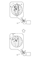
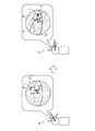
- FIG. 4 is a diagram for explaining a process of generating rotation information according to the head direction S according to the present embodiment.
- the left diagram of FIG. 4 shows a state of the real space 10 and the virtual space 20 in an initial state after the second calibration processing.
- the right diagram of FIG. 4 illustrates a state of the real space 10 and the virtual space 20 when the rotation correction processing is applied in a changed state after the second calibration processing.
- the execution of the second calibration process results in the first reference direction (head direction S in the initial state) and the second reference direction (target region T).
- the rotation amount R of the virtual space 20 is the rotation amount indicated by the angle information generated in the second calibration process.
- the user In changing state, the user along a horizontal plane 11 in the real space 10 (i.e., Z 1 around the axis) to rotate the head direction S, the rotation information generating unit 175, the angle information and the head direction after the change
- the rotation information is regenerated based on S and the virtual space 20 is rotated based on the regenerated rotation information. More specifically, as shown in the right diagram of FIG. 4, the virtual space 20 is rotated with respect to the changed head direction S by the rotation amount R.
- the rotation amount R shown in the left diagram of FIG. 4 is the same as the rotation amount R shown in the right diagram of FIG.
- the position V in the head direction S after the change coincides with the region T ′ in the virtual space 20.
- the region T ' will be described in detail with reference to FIG.
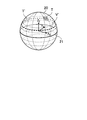
- FIG. 5 is a diagram illustrating an example of a locus V ′ of the position V in the head direction S in the virtual space 20 when the rotation of the virtual space 20 is performed based on the rotation information according to the present embodiment.
- the trajectory V ′ of the position V in the head direction S passes through the target area T and is parallel to the horizontal plane 21 in the virtual space 20. It is.
- An area T ′ shown in the right diagram of FIG. 4 is an area on the locus V ′.
- the user along a horizontal plane 11 in the real space 10 has been described as rotating the head direction S around, of course, the user is provided with a horizontal surface 11 in the real space 10
- the head direction S can be rotated so as to intersect. Even in this case, the above-described effects are similarly exhibited.
- the rotation information may include a quaternion q for rotating the virtual space 20.
- q t is the quaternion representing the rotation in the vertical direction relative to the horizontal surface 11 in the real space 10 for matching the second reference direction in the first reference direction.
- Quaternion q t is generated based on the angle information.
- q h is rotated in a horizontal plane 11 in the real space 10 between the head direction S and the first reference direction (i.e., rotation about the Z 1 axis) is a quaternion representing a.
- Quaternion q h based on the angle of the horizontal plane 11 between the first reference direction and the current head direction S, is generated.
- the operation mode selection unit 179 selects an operation mode of the output control unit 177.
- the operation mode selection unit 179 can select the operation mode from the first operation mode or the second operation mode.
- the first operation mode is an operation mode in which the rotation of the second space using the above-described rotation information is not performed. Specifically, in the first operation mode, while the second calibration process is performed, the rotation correction process in the changing state is not performed. In the first operation mode, an image corresponding to the head direction S described with reference to the right diagram of FIG. 2 is displayed. That is, in the second operation mode, the space recognition of the real space 10 and the space recognition of the virtual space 20 by the user do not match.
- the second operation mode is an operation mode for rotating the second space using the above-described rotation information. Specifically, in the second operation mode, a second calibration process and a rotation correction process in a changed state are performed. In the second operation mode, the image corresponding to the head direction S described with reference to the right diagram of FIG. 4 and FIG. 5 is displayed. That is, in the second operation mode, the space recognition of the real space 10 and the space recognition of the virtual space 20 by the user match. By selecting such an operation mode, the output control unit 177 can operate in an appropriate operation mode.
- the operation mode selection unit 179 may select an operation mode based on operation input information from the operation input unit 120. For example, the operation input unit 120 accepts an input of an operation mode selection instruction instructing to select the first operation mode or the second operation mode, and the operation mode selection unit 179 operates according to the operation mode selection instruction. Select a mode.
- the operation mode selection unit 179 may select the second operation mode by default when reproducing the VR content. Then, the operation mode selection unit 179 may temporarily select the first operation mode according to an operation mode selection instruction from the user.
- the output control unit 177 may cause the display unit 140 to display information indicating a horizontal line of the virtual space 20.
- the information indicating the horizontal line here is information indicating a line parallel to the horizontal plane 21 of the virtual space 20.
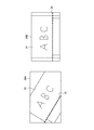
- FIG. 6 is a diagram illustrating an example of a screen displayed by the HMD 1 according to the present embodiment.
- Screen 30A shown in FIG. 6 is displayed in the first operation mode
- screen 30B shown in FIG. 6 is displayed in the second operation mode.
- Any of these screens also user along a horizontal plane 11 in the real space 10 (i.e., Z 1 around the axis) when rotating the head direction S, which is an example of a screen displayed.
- the horizontal direction of these screens is parallel to the horizontal plane 11 of the real space 10.
- Each of these screens is displayed based on a spherical image of the room where the whiteboard 31 is placed.
- a line 32 parallel to the horizontal plane 21 of the virtual space 20 is displayed. Since the line 32 is displayed obliquely with respect to the screen 30A, it can be seen that the horizontal plane 11 of the real space 10 and the horizontal plane of the virtual space 20 intersect. Thereby, the user can recognize that the output control unit 177 is operating in the first operation mode.
- a line 32 parallel to the horizontal plane 21 of the virtual space 20 is displayed. Since the line 32 is displayed horizontally with respect to the screen 30B, it can be seen that the horizontal plane 11 of the real space 10 and the horizontal plane of the virtual space 20 are parallel. Thereby, the user can recognize that the output control unit 177 is operating in the second operation mode.
- the output control unit 177 may localize the sound image of the sound in the virtual space 20 based on the rotation information. For example, when the output position of the sound in the virtual space 20 is defined in the VR content, the output control unit 177 specifies the output position of the sound by rotating the sound output position based on the corrected rotation information. Then, the output control unit 177 localizes the sound image so that the sound in the virtual space 20 is output from the specified output position. Accordingly, the output control unit 177 can prevent a deviation between the image display and the output position of the audio, and can provide a more natural and immersive user experience.
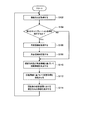
- FIG. 7 is a flowchart illustrating an example of the flow of a rotation correction process performed by the HMD 1 according to the present embodiment.
- the gaze-related direction acquisition unit 171 acquires the head direction S of the user (step S102).
- the rotation information generation unit 175 determines whether to execute the second calibration process (Step S104). For example, when a calibration start instruction is input, the rotation information generation unit 175 determines that the second calibration process is to be performed. When it is determined that the second calibration process is to be performed (step S104 / YES), the rotation information generation unit 175 acquires the angle information (step S106), and the storage unit 160 stores the acquired angle information. (Step S108). Thereafter, the process proceeds to step S110. If it is determined that the second calibration process is not to be performed (step S104 / NO), the process proceeds to step S110.
- the rotation information generation unit 175 generates rotation information based on the head direction S and the angle information stored in the storage unit 160 (Step S110).
- the output control unit 177 rotates the virtual space 20 based on the rotation information (Step S112).
- the output control unit 177 causes the display unit 140 to display an image of the head direction S in the rotated virtual space 20 (step S114).
- Use Case (1) First Use Case The first use case relates to a life log.
- the VR content is a life log recorded as a spherical image.
- the user displays the scene to be remembered on the HMD 1 in order to make it easier to remember the contents.
- the user causes the important part of the scene to be remembered to be subjected to the second calibration processing with the specific position.
- the spherical image of the scene is displayed on the HMD 1.
- the user causes the HMD 1 to execute a second calibration process in which the face of the family requesting to buy a shampoo is set as a specific position, and rotates the omnidirectional image based on the rotation information.
- This allows the user to remove the shampoo from the family in which the face of the family requesting to buy the shampoo is located in a direction that is easy to see, and the spatial recognition of the real space 10 and the spatial recognition of the virtual space 20 by the user match. It is possible to appreciate the image of the scene requested to be purchased.
- the second use case relates to watching sports.
- the VR content is a sports game recorded in a spherical image.
- the spectator seat is located higher than the court / ground where the game is being played, and when viewed from the spectator seat, the court / ground is located downward. Therefore, when the camera viewpoint of the omnidirectional image is located at the spectator seat and the first calibration process is performed, the user is forced to always point the head direction S downward.
- the user causes the HMD 1 to execute a second calibration process with the court / ground as a specific position, and rotates the omnidirectional image based on the rotation information. Accordingly, the user can view an image of a sports game in which the court / ground is located in a direction that is easy to see, and the spatial recognition of the real space 10 and the spatial recognition of the virtual space 20 by the user match. .
- the user can cause the HMD 1 to execute the second calibration process before and after the switching, so that the user can always view the image of the important area while turning the head direction S in a direction that is easy to see. Becomes possible.
- Third use case A third use case relates to a remote-controlled robot.
- the user operates the operating device while wearing the HMD 1, and remotely controls the robot having the work arm.
- the spherical image captured by the spherical camera mounted on the robot is displayed by the HMD 1.
- a second calibration process is performed in which the work position at the tip of the work arm is set as the specific position, and the rotation of the omnidirectional image based on the above-described rotation information is performed. Accordingly, the user can view an image of the work space in which the work position of the tip of the work arm is located in a direction that is easy to see, and the space recognition of the real space 10 and the space recognition of the virtual space 20 by the user match. It becomes possible. As a result, it is possible to reduce the physical load on the user and improve the work efficiency.
- the first reference direction is described as being the direction of the horizontal plane 11 in the real space 10; however, the present technology is not limited to such an example.
- the first reference direction may be a direction shifted by a predetermined angle below the horizontal plane 11 in the real space 10.
- the first reference direction is a direction shifted from 5 degrees to 10 degrees below the horizontal plane 11 in the real space 10. This makes it possible to execute the second calibration process with the direction most visible to the user as the first reference direction.
- the center position of the display unit is often shifted from the viewpoint of the user by 5 degrees to 10 degrees in design. This is because experience has shown that such an angle is easy for the user to see.
- FIG. 8 is a diagram for explaining the second calibration process according to the first modification.
- the left diagram of FIG. 8 illustrates the state of the real space 10 and the virtual space 20 in the initial state after the first calibration process
- the right diagram of FIG. 8 illustrates the initial state after the second calibration process.
- 1 shows a state of a real space 10 and a virtual space 20.
- the left diagram in FIG. 8 is the same as the left diagram in FIG.
- the head direction S of the user coincides with the first reference direction.
- the first reference direction is a direction shifted by a predetermined angle below the horizontal plane 11 in the real space 10.
- the first reference direction matches the second reference direction. Therefore, as shown in the right diagram of FIG. 8, when the user turns the head direction S downward by a predetermined angle based on the horizontal plane 11 in the real space 10, that is, the head direction S matches the first reference direction. Then, the position V in the head direction S matches the target area T in the second reference direction.
- the first reference direction is a direction shifted downward by a predetermined angle with respect to the horizontal plane 11 in the real space 10. Therefore, the target area T is moved to the horizontal plane 11 in the real space 10 by the second calibration process. It will be located lower than this.
- the virtual space 20 is described as an omnidirectional image, but the present technology is not limited to such an example.
- the virtual space 20 may be a modeled three-dimensional space.
- the HMD 1 changes the posture of the camera in the modeled three-dimensional space according to the change in the head direction S of the user, and displays an image obtained by the camera. Further, the HMD 1 rotates the horizontal plane (coordinate system) of the entire world in the three-dimensional space modeled according to the rotation information.
- the HMD 1 may move the camera viewpoint up and down instead of using the rotation information to rotate the horizontal plane of the entire world in the three-dimensional space as the rotation correction processing.
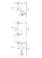
- FIG. 9 is a diagram for explaining a rotation correction process according to the second modification.
- the first reference direction is the direction of the horizontal plane 11 of the real space 10. That is, in the initial state, it is assumed that the head direction S of the user faces the horizontal plane 11 of the real space 10.
- FIG. 9 shows the relationship between the position of the camera C and the position of the target area T in the virtual space 20 when the first calibration processing has been performed.
- the imaging direction 23 of the camera C is parallel to the ground 22.
- the height of the camera C from the ground 22 is L
- the height of the target area T from the ground 22 is L + H.
- the imaging direction 23 of the camera C is parallel to the ground 22, and the angle between the imaging direction 23 of the camera C and the direction 24 from the camera C to the target area T is ⁇ .
- FIG. 9 shows the position of the camera C in the virtual space 20 in the initial state and the target area T when the height of the camera viewpoint is moved to the height of the target area T as the second calibration processing. Shows the relationship with the position.
- the imaging direction 23 of the camera C is oriented in a direction parallel to the ground 22.
- the height of the camera C from the ground 22 is L + H, which is the same as the height L + H of the target area T from the ground 22. Therefore, in the initial state, the imaging direction 23 of the camera C is parallel to the ground 22, and coincides with the imaging direction 23 of the camera C and the direction 24 from the camera C to the target area T.
- the imaging direction 23 of the camera C rotates horizontally while keeping the ground 22 parallel. Therefore, an image of an area on a trajectory that passes through the target area T and is parallel to the ground 22 is displayed. Therefore, since the space recognition of the real space 10 and the space recognition of the virtual space 20 by the user match, it is possible to prevent the user from feeling uncomfortable.
- the right diagram of FIG. 9 illustrates the relationship between the position of the camera C and the position of the target region T in the virtual space 20 in the initial state when the virtual space 20 is rotated based on the rotation information as the second calibration process. Is shown.
- the posture of the camera C is inclined by ⁇ , and as a result, the imaging direction 23 of the camera C matches the direction 24 from the camera C to the target area T.
- the imaging direction 23 of the camera C is in a direction crossing the ground 22.
- the virtual height of the camera C from the ground 22 is L / cos ⁇
- the height of the target area T from the ground 22 is L + H.
- the camera C rotates parallel to the ground 22 while maintaining the inclination ⁇ . Thereby, an image of an area on a trajectory that passes through the target area T and is parallel to the ground 22 is displayed. Therefore, since the space recognition of the real space 10 and the space recognition of the virtual space 20 by the user match, it is possible to prevent the user from feeling uncomfortable.
- the height of the camera C is L + H.
- the virtual height of the camera C is L / cos ⁇ .
- ⁇ satisfies ⁇ / 2 ⁇ ⁇ / 2. That is, when the camera viewpoint is moved up and down, the amount of change in the height of the camera C is
- Expression (2) when the relationship of Expression (3) is satisfied, the height change of the camera C is smaller when the virtual space 20 is rotated than when the camera viewpoint is moved up and down. Can be said to be superior.
- > L / cos ⁇ L, tan ⁇ H / D (2) (1 ⁇ cos ⁇ ) 2 / (1 ⁇ cos 2 ⁇ ) ⁇ (D / L) 2 (3)
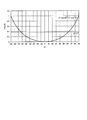
- FIG. 10 is a graph showing the amount of change in the height of the camera viewpoint when the camera viewpoint is moved up and down and when the virtual space 20 is rotated in the second modification.
- ⁇ is ⁇ 60 degrees to +60 degrees
- the above equation (3) is established.
- ⁇ is ⁇ 90 degrees to ⁇ 60 degrees and when ⁇ is +60 degrees to +90 degrees
- the above equation (3) is changed to It doesn't hold. That is, in many cases, it is understood that the above equation (3) holds. From this, it can be seen that, in many cases, when the virtual space 20 is rotated, the height change of the camera C is smaller and superior than when the camera viewpoint is moved up and down.
- FIG. 11 is a block diagram illustrating an example of a hardware configuration of the information processing apparatus according to the present embodiment.
- the information processing device 900 illustrated in FIG. 11 can realize, for example, the information processing device 1 illustrated in FIG.
- Information processing by the information processing apparatus 1 according to the present embodiment is realized by cooperation of software and hardware described below.
- the information processing apparatus 900 includes a CPU (Central Processing Unit) 901, a ROM (Read Only Memory) 902, a RAM (Random Access Memory) 903, and a host bus 904 a.
- the information processing device 900 includes a bridge 904, an external bus 904b, an interface 905, an input device 906, an output device 907, a storage device 908, a drive 909, a connection port 911, and a communication device 913.
- the information processing device 900 may include a processing circuit such as an electric circuit, a DSP, or an ASIC, instead of or in addition to the CPU 901.
- the CPU 901 functions as an arithmetic processing device and a control device, and controls overall operations in the information processing device 900 according to various programs. Further, the CPU 901 may be a microprocessor.
- the ROM 902 stores programs used by the CPU 901 and operation parameters.
- the RAM 903 temporarily stores a program used in the execution of the CPU 901 and parameters that change as appropriate in the execution.
- the CPU 901 may form, for example, the control unit 170 illustrated in FIG.
- the CPU 901, the ROM 902, and the RAM 903 are mutually connected by a host bus 904a including a CPU bus and the like.
- the host bus 904a is connected via a bridge 904 to an external bus 904b such as a PCI (Peripheral Component Interconnect / Interface) bus.
- PCI Peripheral Component Interconnect / Interface
- the host bus 904a, the bridge 904, and the external bus 904b do not necessarily need to be separately configured, and these functions may be mounted on one bus.
- the input device 906 is realized by a device to which information is input by a user, such as a mouse, a keyboard, a touch panel, a button, a microphone, a switch, and a lever. Further, the input device 906 may be, for example, a remote control device using infrared rays or other radio waves, or may be an externally connected device such as a mobile phone or a PDA corresponding to the operation of the information processing device 900. . Further, the input device 906 may include, for example, an input control circuit that generates an input signal based on information input by a user using the above-described input unit and outputs the input signal to the CPU 901. By operating the input device 906, the user of the information processing device 900 can input various data to the information processing device 900 or instruct a processing operation. These input devices 906 can form, for example, the operation input unit 120 shown in FIG.
- the input device 906 may be formed by a device that detects information about the user.
- the input device 906 includes various sensors such as an image sensor (for example, a camera), a depth sensor (for example, a stereo camera), an acceleration sensor, a gyro sensor, a geomagnetic sensor, an optical sensor, a sound sensor, a distance measuring sensor, and a force sensor. May be included.
- the input device 906 is used for information about the state of the information processing device 900 itself, such as the posture and the moving speed of the information processing device 900, and information about the surrounding environment of the information processing device 900, such as brightness and noise around the information processing device 900. May be obtained.
- the input device 906 receives a GNSS signal (for example, a GPS signal from a GPS (Global Positioning System) satellite) from a GNSS (Global Navigation Satellite System) satellite, and receives position information including the latitude, longitude, and altitude of the device.
- a GNSS module for measuring may be included.
- the input device 906 may be a device that detects the position by Wi-Fi (registered trademark), transmission / reception with a mobile phone / PHS / smartphone, or the like, or short-range communication.
- These input devices 906 may form, for example, the sensor unit 110 shown in FIG.
- the output device 907 is formed of a device capable of visually or audibly notifying the user of the acquired information. Examples of such devices include CRT display devices, liquid crystal display devices, plasma display devices, EL display devices, display devices such as laser projectors, LED projectors and lamps, audio output devices such as speakers and headphones, and printer devices. . Another display device is a retinal projection display that projects an image directly on a user's retina.
- the output device 907 outputs, for example, results obtained by various processes performed by the information processing device 900. Specifically, the display device visually displays the results obtained by various processes performed by the information processing device 900 in various formats such as text, images, tables, and graphs.
- the audio output device converts an audio signal composed of reproduced audio data, acoustic data, and the like into an analog signal and outputs it audibly.
- the display device may form, for example, the display unit 140 illustrated in FIG.
- the audio output device may form, for example, the audio output unit 150 shown in FIG.
- the storage device 908 is a data storage device formed as an example of a storage unit of the information processing device 900.
- the storage device 908 is realized by, for example, a magnetic storage device such as an HDD, a semiconductor storage device, an optical storage device, or a magneto-optical storage device.
- the storage device 908 may include a storage medium, a recording device that records data on the storage medium, a reading device that reads data from the storage medium, a deletion device that deletes data recorded on the storage medium, and the like.
- the storage device 908 stores programs executed by the CPU 901 and various data, various data acquired from the outside, and the like.
- the storage device 908 may form, for example, the storage unit 160 illustrated in FIG.
- the drive 909 is a reader / writer for a storage medium, and is built in or external to the information processing apparatus 900.
- the drive 909 reads information recorded on a removable storage medium such as a mounted magnetic disk, optical disk, magneto-optical disk, or semiconductor memory, and outputs the information to the RAM 903.
- the drive 909 can also write information on a removable storage medium.
- connection port 911 is an interface connected to an external device, and is a connection port with an external device capable of transmitting data by USB (Universal Serial Bus), for example.
- USB Universal Serial Bus
- the communication device 913 is a communication interface formed of, for example, a communication device for connecting to the network 920.
- the communication device 913 is, for example, a communication card for a wired or wireless LAN (Local Area Network), LTE (Long Term Evolution), Bluetooth (registered trademark), or WUSB (Wireless USB).
- the communication device 913 may be a router for optical communication, a router for ADSL (Asymmetric Digital Subscriber Line), a modem for various communication, or the like.
- the communication device 913 can transmit and receive signals and the like to and from the Internet and other communication devices in accordance with a predetermined protocol such as TCP / IP.
- the communication device 913 may form, for example, the communication unit 130 illustrated in FIG.
- the network 920 is a wired or wireless transmission path for information transmitted from a device connected to the network 920.
- the network 920 may include a public line network such as the Internet, a telephone line network, a satellite communication network, various LANs including Ethernet (registered trademark) (Local Area Network), a WAN (Wide Area Network), and the like.
- the network 920 may include a dedicated line network such as an IP-VPN (Internet ⁇ Protocol-Virtual ⁇ Private ⁇ Network).
- a computer program for realizing each function of the information processing device 900 according to the present embodiment as described above can be created and mounted on a PC or the like.
- a computer-readable recording medium in which such a computer program is stored can be provided.
- the recording medium is, for example, a magnetic disk, an optical disk, a magneto-optical disk, a flash memory, or the like.
- the above-described computer program may be distributed, for example, via a network without using a recording medium.
- the information processing apparatus 1 includes the first reference direction in the real space 10 and the virtual space when the coordinate system of the real space 10 is associated with the coordinate system of the virtual space 20.
- the angle information indicating the angle with the second reference direction at 20 is obtained.
- the information processing device 1 generates rotation information for rotating the virtual space 20 based on the angle information and the direction related to the line of sight of the user in the real space 10.
- the information processing apparatus 1 can rotate the virtual space 20 and display an image of an area in the direction related to the user's line of sight in the rotated virtual space 20.
- the user can view the image of the area in the first reference direction in the virtual space 20 without tilting the head up and down.
- the virtual space 20 is always inclined with respect to the direction related to the user's line of sight.
- the user rotates the head direction S along the horizontal plane 11 of the real space 10
- the image of the area on the trajectory parallel to 21 is displayed. This prevents the user from perceiving the space between the virtual space and the real space.
- control unit 170 includes the sensor unit 110, the operation input unit 120, the communication unit 130, the display unit 140, the audio output unit 150, and the storage unit 160. It may be provided in a device such as a server connected via a network or the like.
- the angle between the first reference direction in the first space and the second reference direction in the second space when the coordinate system of the first space is associated with the coordinate system of the second space A generation unit that generates rotation information for rotating the second space based on the angle information indicating the direction and the direction related to the line of sight of the user in the first space.
- An information processing apparatus comprising: (2) The information processing device according to (1), wherein the rotation information is information for rotating the second space in a vertical direction with respect to a horizontal plane in the first space. (3) The rotation information is for rotating the second space in a direction from the second reference direction to a first reference direction with respect to a line of sight of the user by an angle indicated by the angle information.
- the information processing apparatus which is information.
- the angle information is information indicating an angle in a vertical direction with respect to a horizontal plane in the first space between the first reference direction and the second reference direction.
- the information processing apparatus according to any one of (3).
- the information processing apparatus includes an output control unit configured to rotate the second space using the rotation information and to display information indicating the rotated second space on a display unit, The information processing device according to any one of 6).
- the information processing apparatus further includes an operation mode selection unit that selects an operation mode of the output control unit from a first operation mode or a second operation mode.
- the first operation mode is an operation mode in which the rotation of the second space using the rotation information is not performed,
- the information processing device according to (7), wherein the second operation mode is an operation mode in which the second space is rotated using the rotation information.
- the information processing device (9) The information processing device according to (7) or (8), wherein the output control unit displays information indicating a horizontal line of the second space. (10) The information processing device according to any one of (7) to (9), wherein the output control unit localizes a sound image of a sound in the second space based on the rotation information. (11) The information processing apparatus according to any one of (1) to (10), wherein the direction regarding the user's line of sight is the user's line of sight. (12) The information processing apparatus according to any one of (1) to (10), wherein the direction related to the user's line of sight is a head direction of the user. (13) The information processing apparatus according to any one of (1) to (12), wherein the first reference direction is a direction of a horizontal plane in the first space.
- the information processing apparatus according to any one of (1) to (12), wherein the first reference direction is a direction shifted downward by a predetermined angle with respect to a horizontal plane in the first space.
- the second reference direction is a direction of a specific position in the second space.
- the specific position is set based on a direction related to a line of sight of the user.
- the information processing apparatus according to any one of (1) to (16), wherein the first space is a real space, and the second space is a spherical image.
- HMD Reference Signs List 10 real space 11 horizontal plane of real space 20 virtual space 21 horizontal plane of virtual space 110 sensor unit 120 operation input unit 130 communication unit 140 display unit 150 sound output unit 160 storage unit 170 control unit 171 gaze-related direction acquisition unit 173 acquisition of virtual space information Unit 175 Rotation information generation unit 177 Output control unit 179 Operation mode selection unit
Landscapes
- Engineering & Computer Science (AREA)
- General Engineering & Computer Science (AREA)
- Theoretical Computer Science (AREA)
- Physics & Mathematics (AREA)
- General Physics & Mathematics (AREA)
- Human Computer Interaction (AREA)
- Computer Graphics (AREA)
- Computer Hardware Design (AREA)
- Software Systems (AREA)
- User Interface Of Digital Computer (AREA)
- Processing Or Creating Images (AREA)
- Position Input By Displaying (AREA)
Abstract
L'invention concerne un dispositif de traitement d'informations équipé d'une unité de génération (175) permettant de générer des informations de rotation pour faire pivoter un second espace (20) d'après des informations d'angle indiquant un angle entre une première direction de référence dans un premier espace (10) et une seconde direction de référence dans le second espace lorsqu'un système de coordonnées du premier espace et un système de coordonnées du second espace sont associés l'un à l'autre, ainsi qu'une direction associée à la ligne de visée de l'utilisateur dans le premier espace.
Applications Claiming Priority (2)
| Application Number | Priority Date | Filing Date | Title |
|---|---|---|---|
| JP2018-168698 | 2018-09-10 | ||
| JP2018168698A JP2020042480A (ja) | 2018-09-10 | 2018-09-10 | 情報処理装置、情報処理方法及びプログラム |
Publications (1)
| Publication Number | Publication Date |
|---|---|
| WO2020054585A1 true WO2020054585A1 (fr) | 2020-03-19 |
Family
ID=69777050
Family Applications (1)
| Application Number | Title | Priority Date | Filing Date |
|---|---|---|---|
| PCT/JP2019/035078 Ceased WO2020054585A1 (fr) | 2018-09-10 | 2019-09-05 | Dispositif de traitement d'informations, procédé de traitement d'informations et programme |
Country Status (2)
| Country | Link |
|---|---|
| JP (1) | JP2020042480A (fr) |
| WO (1) | WO2020054585A1 (fr) |
Cited By (1)
| Publication number | Priority date | Publication date | Assignee | Title |
|---|---|---|---|---|
| CN117160029A (zh) * | 2023-08-31 | 2023-12-05 | 江西格如灵科技股份有限公司 | 一种vr手柄检测方法及系统 |
Citations (2)
| Publication number | Priority date | Publication date | Assignee | Title |
|---|---|---|---|---|
| JP2017201524A (ja) * | 2017-04-27 | 2017-11-09 | 株式会社コロプラ | 仮想空間を提供する方法、プログラム、および記録媒体 |
| JP2018010487A (ja) * | 2016-07-13 | 2018-01-18 | 株式会社バンダイナムコエンターテインメント | シミュレーションシステム及びプログラム |
-
2018
- 2018-09-10 JP JP2018168698A patent/JP2020042480A/ja active Pending
-
2019
- 2019-09-05 WO PCT/JP2019/035078 patent/WO2020054585A1/fr not_active Ceased
Patent Citations (2)
| Publication number | Priority date | Publication date | Assignee | Title |
|---|---|---|---|---|
| JP2018010487A (ja) * | 2016-07-13 | 2018-01-18 | 株式会社バンダイナムコエンターテインメント | シミュレーションシステム及びプログラム |
| JP2017201524A (ja) * | 2017-04-27 | 2017-11-09 | 株式会社コロプラ | 仮想空間を提供する方法、プログラム、および記録媒体 |
Cited By (1)
| Publication number | Priority date | Publication date | Assignee | Title |
|---|---|---|---|---|
| CN117160029A (zh) * | 2023-08-31 | 2023-12-05 | 江西格如灵科技股份有限公司 | 一种vr手柄检测方法及系统 |
Also Published As
| Publication number | Publication date |
|---|---|
| JP2020042480A (ja) | 2020-03-19 |
Similar Documents
| Publication | Publication Date | Title |
|---|---|---|
| US12112443B2 (en) | Display control apparatus, display control method, and program | |
| US11030771B2 (en) | Information processing apparatus and image generating method | |
| JP6505556B2 (ja) | 情報処理装置および画像生成方法 | |
| KR20200096901A (ko) | 가상 현실 (vr) 디바이스에 의해 디스플레이되는 가상 컨텐트를 네비게이트하는 방법 및 장치 | |
| JP2018205913A (ja) | 仮想空間を提供するためにコンピュータで実行される方法、プログラム、および、情報処理装置 | |
| WO2020241189A1 (fr) | Dispositif de traitement d'informations, procédé de traitement d'informations et programme | |
| US11151804B2 (en) | Information processing device, information processing method, and program | |
| US10515481B2 (en) | Method for assisting movement in virtual space and system executing the method | |
| JPWO2018216355A1 (ja) | 情報処理装置、情報処理方法、及びプログラム | |
| CN107851334A (zh) | 信息处理装置 | |
| JP7702675B2 (ja) | 映像表示システム | |
| JP6518645B2 (ja) | 情報処理装置および画像生成方法 | |
| JP7636126B2 (ja) | 情報処理装置および画像生成方法 | |
| WO2020054585A1 (fr) | Dispositif de traitement d'informations, procédé de traitement d'informations et programme | |
| JP2018165985A (ja) | 情報処理装置および画像生成方法 | |
| JP2018206340A (ja) | 仮想空間を提供するためにコンピュータで実行される方法、プログラム、および、情報処理装置 | |
| WO2023248832A1 (fr) | Système de visualisation à distance et système d'imagerie sur site | |
| JP2018120521A (ja) | 仮想空間を提供するための方法、当該方法をコンピュータに実行させるためのプログラム、および当該プログラムを実行するための情報処理装置 | |
| JP2025010773A (ja) | 情報処理システム、情報処理方法、プログラム |
Legal Events
| Date | Code | Title | Description |
|---|---|---|---|
| 121 | Ep: the epo has been informed by wipo that ep was designated in this application |
Ref document number: 19860800 Country of ref document: EP Kind code of ref document: A1 |
|
| NENP | Non-entry into the national phase |
Ref country code: DE |
|
| 122 | Ep: pct application non-entry in european phase |
Ref document number: 19860800 Country of ref document: EP Kind code of ref document: A1 |