WO2020054589A1 - Structure de guide d'air - Google Patents
Structure de guide d'air Download PDFInfo
- Publication number
- WO2020054589A1 WO2020054589A1 PCT/JP2019/035119 JP2019035119W WO2020054589A1 WO 2020054589 A1 WO2020054589 A1 WO 2020054589A1 JP 2019035119 W JP2019035119 W JP 2019035119W WO 2020054589 A1 WO2020054589 A1 WO 2020054589A1
- Authority
- WO
- WIPO (PCT)
- Prior art keywords
- air guide
- air
- vehicle
- radiator
- lid
- Prior art date
- Legal status (The legal status is an assumption and is not a legal conclusion. Google has not performed a legal analysis and makes no representation as to the accuracy of the status listed.)
- Ceased
Links
Images

Classifications
-
- B—PERFORMING OPERATIONS; TRANSPORTING
- B60—VEHICLES IN GENERAL
- B60K—ARRANGEMENT OR MOUNTING OF PROPULSION UNITS OR OF TRANSMISSIONS IN VEHICLES; ARRANGEMENT OR MOUNTING OF PLURAL DIVERSE PRIME-MOVERS IN VEHICLES; AUXILIARY DRIVES FOR VEHICLES; INSTRUMENTATION OR DASHBOARDS FOR VEHICLES; ARRANGEMENTS IN CONNECTION WITH COOLING, AIR INTAKE, GAS EXHAUST OR FUEL SUPPLY OF PROPULSION UNITS IN VEHICLES
- B60K11/00—Arrangement in connection with cooling of propulsion units
- B60K11/02—Arrangement in connection with cooling of propulsion units with liquid cooling
- B60K11/04—Arrangement or mounting of radiators, radiator shutters, or radiator blinds
Definitions
- the present disclosure relates to an air guide structure for a vehicle.
- Patent Literature 1 discloses a structure in which a vehicle is provided with a downwardly inclined guide plate that crosses a vehicle body frame on the front side of a radiator.
- Patent Document 1 in a vehicle having an air guide extending downward from a lower end of a radiator, when receiving liquid on the front surface of the air guide (for example, when the vehicle is submerged), the air guide is pressed by the liquid. There is a problem that the air guide is broken due to the force that is applied.
- an object of the present disclosure is to provide an air guide structure that is not easily broken when an air guide of a radiator receives a liquid.
- the air guide includes: a radiator of a vehicle; and an air guide that extends downward from a lower end of the radiator and that flows air to the radiator. Provides an air guide structure having an opening through which liquid received by a front surface of the air guide flows out of the air guide to the outside of the air guide.
- a fan is provided behind the radiator, and further has a fan for flowing air from the front to the rear of the radiator, wherein the air guide receives the liquid on a front surface of the air guide.
- the air conditioner may further include a lid that moves to a second position in which the opening is closed when air flows from the front to the rear in the front-rear direction of the vehicle by the operation of the fan.
- the lid is located at the first position where the liquid flows out from the inside of the air guide toward the outside of the air guide through the opening when receiving the liquid on the front surface of the air guide. It may be. Further, when the air guide does not receive the liquid, the air flows from the front to the rear in the front-rear direction of the vehicle inside the air guide by the operation of the fan when the air guide does not receive the liquid.
- the lid is located at the first position where the opening is opened by being pushed by the liquid from the inside of the air guide to the outside of the air guide when the vehicle is being flooded. After the vehicle is submerged, the air may flow from the front to the rear in the front-rear direction of the vehicle by the operation of the fan, and the opening may be closed at the second position. .
- the air guide includes a bottom plate portion extending downward from a lower end of the radiator, and a plurality of side plates provided at both ends of the bottom plate portion in the vehicle width direction of the vehicle so as to be orthogonal to the bottom plate portion.
- the opening formed in each of the plurality of side plate parts, and the lid part displaceable with respect to the side plate part and shielding at least a part of the opening part. Is also good.
- the air guide includes a bottom plate portion extending downward from a lower end of the radiator, and a plurality of side plates provided at both ends of the bottom plate portion in the vehicle width direction of the vehicle so as to be orthogonal to the bottom plate portion.
- the lid portion may not be parallel to the side plate portion when in the first position.
- the rear end of the lid in the front-rear direction of the vehicle may not be in contact with the outer surface of the side plate.
- the air guide structure there is an effect that the air guide of the radiator is hardly broken when receiving the liquid.
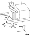
- FIG. 1 shows a state in which an air guide structure according to the present embodiment is provided in a vehicle.
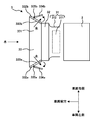
- FIG. 2 shows a state in which the lid of the air guide in the air guide structure according to the present embodiment is open.
- FIG. 3 shows a state in which the lid of the air guide in the air guide structure according to the present embodiment is closed.
- FIG. 1 is a diagram illustrating a state in which an air guide structure 3 according to the present embodiment is provided in a vehicle.
- the air guide structure 3 has a fan 31, a radiator 32, and an air guide 33.
- FIG. 2 is a diagram illustrating a state in which the lid 334 of the air guide 33 in the air guide structure 3 according to the present embodiment is open.
- FIG. 3 is a diagram illustrating a state in which the lid 334 of the air guide 33 in the air guide structure 3 according to the present embodiment is closed. 2 and 3 are views showing the structure as viewed from above the vehicle.
- the vehicle has a side frame 1, an engine 2, an air guide structure 3, and an intercooler 4.
- the side frame 1 is a member extending in the front-rear direction of the vehicle. Two side frames 1 are provided in parallel.
- the engine 2 generates power for driving the vehicle.
- the engine 2 is, for example, a gasoline engine or a diesel engine.
- the engine 2 supplies fuel (for example, gasoline or light oil) and air to burn and generate power and generate exhaust gas.
- the engine 2 is provided behind the fan 31 in the front-rear direction of the vehicle.
- the air guide structure 3 has a function of improving the cooling capacity of the engine 2.
- the air guide structure 3 is provided in front of the engine 2 in the front-rear direction of the vehicle. The details of the air guide structure 3 will be described later.
- the intercooler 4 is a device for cooling air whose temperature has increased by being compressed by a supercharger (for example, a turbocharger).
- the supercharger is a device that uses the exhaust gas of the engine 2 to increase the pressure, that is, the density of the air supplied to the engine 2.
- the intercooler 4 is provided in front of the radiator 32.
- the upper end of the intercooler 4 is located below the upper end of the radiator 32 in the height direction of the vehicle.
- the intercooler 4 has an air inlet through which cooling air (for example, traveling wind or air flowing by the fan 31) flows into a front surface of the vehicle in the front-rear direction, and supplies the cooling air to a rear surface of the intercooler 4. It has an outflow air outlet.
- the intercooler 4 heat-exchanges air flowing from the front in the front-rear direction of the vehicle (for example, traveling air or air flowing by the fan 31) with air having a higher temperature flowing from the supercharger. Cools the heated air that flows from the feeder.
- the air flowing out of the intercooler 4 deprives the heat of the air flowing from the supercharger in the intercooler 4, so that the temperature rises as compared with the air flowing into the intercooler 4.
- the fan 31 is a blower for flowing air.
- the fan 31 has a fan body 311 and a fan cover 312.
- the fan body 311 has, for example, a rotating shaft and a plurality of blades provided on the outer surface of the rotating shaft, and the air flows by rotating the rotating shaft and moving the plurality of blades.
- the fan body 311 is housed inside the fan cover 312.
- the fan cover 312 is a cover that houses the fan body 311 inside.
- the fan cover 312 has a substantially cylindrical shape, for example, and is provided outside the fan main body 311.
- the fan cover 312 has an inflow port into which air flows in a front surface of the vehicle in the front-rear direction, and an outflow port through which the air flows out in a rear surface.
- a front end of the fan cover 312 in the front-rear direction of the vehicle is connected to, for example, a rear end of the radiator 32.
- the fan 31 is provided in front of the engine 2. Specifically, the fan 31 is provided behind the radiator 32 in the front-rear direction of the vehicle and in front of the engine 2.
- the fan body 311 is connected to the engine 2 via a shaft, and has a structure in which the fan body 311 is driven to rotate by receiving power from the engine 2, but may be an electric fan.
- the fan 31 allows the air to flow from the front to the rear in the front-rear direction of the vehicle when the fan body 311 operates.
- the fan 31 allows air to flow from the front to the rear of the radiator 32 and the intercooler 4, for example.
- the radiator 32 cools the heat transfer medium that cools the engine 2.
- the heat transfer medium is cooling water for cooling the engine 2.
- the heat transfer medium is circulating between the radiator 32 and the engine 2.
- the radiator 32 cools the heat transfer medium heated by flowing through the engine 2.
- the radiator 32 is provided in front of the engine 2 and the fan 31.
- the radiator 32 has an air inlet through which cooling air (for example, traveling wind or air flowing by the fan 31) flows into a front surface of the vehicle in the front-rear direction, and causes the cooling air to flow out to a rear surface of the radiator 32. It has an air outlet.
- the radiator 32 is heated by exchanging heat between air flowing in from the front in the front-rear direction of the vehicle (for example, traveling wind or air flowing by the fan 31) and a heated heat transfer medium flowing out of the engine 2. Cool the heat transfer medium.
- the heat transfer medium cooled by the radiator 32 flows into the engine 2.
- the temperature of the air flowing out of the radiator 32 is higher than that of the air flowing into the radiator 32 by removing heat of the heat transfer medium flowing out of the engine 2 in the radiator 32.
- the air guide 33 is provided so as to extend downward from the lower end of the radiator 32, and is a guide member for flowing air, for example, a running wind at a lower part of the vehicle, to the radiator 32.
- the traveling wind flowing from the front to the rear in the front-rear direction of the vehicle flows toward the radiator 32 along the air guide 33 and flows forward of the radiator 32.
- the air guide 33 has a bottom plate 331, a plurality of side plates 332, a plurality of openings 333, a plurality of lids 334, and a plurality of hinges 335.
- the bottom plate portion 331 has, for example, a flat plate shape.
- the bottom plate 331 extends downward from the lower end of the radiator 32.
- the bottom plate 331 is provided at a predetermined angle with respect to the height direction of the vehicle such that, for example, the lower end of the bottom plate 331 is located forward of the upper end of the bottom plate 331 in the front-rear direction of the vehicle.
- the upper end of the bottom plate 331 is fixed to the lower end of the radiator 32.
- the upper end of the bottom plate 331 may be fixed to the lower end of the radiator 32 via a bracket (not shown).
- the upper end of the bottom plate portion 331 is fixed to, for example, the front surface and the lower end of the radiator 32.
- the plurality of side plate portions 332 are provided at both ends of the bottom plate portion 331 in the vehicle width direction of the vehicle.
- the plurality of side plate portions 332 are provided on the bottom plate portion 331, for example, orthogonal to the bottom plate portion 331.
- a left side plate portion 332a and a right side plate portion 332b are provided as the plurality of side plate portions 332, a left side plate portion 332a and a right side plate portion 332b are provided.
- the left side plate portion 332a is a side plate portion provided at the left end of the bottom plate portion 331 in the vehicle width direction of the vehicle.
- the left side plate portion 332a is provided on the bottom plate portion 331, for example, orthogonal to the bottom plate portion 331.
- the right side plate portion 332b is a side plate portion provided at the right end of the bottom plate portion 331 in the vehicle width direction.
- the right side plate portion 332b is provided on the bottom plate portion 331, for example, orthogonal to the bottom plate portion 331.
- the plurality of openings 333 are openings formed in the plurality of side plate portions 332, respectively.
- the opening 333 allows the liquid received by the front surface of the air guide 33 to flow from the inside of the air guide 33 to the outside of the air guide 33.
- the liquid is, for example, water.
- a left opening 333a and a right opening 333b are provided as the plurality of openings 333.
- the left opening 333a is an opening formed in the left side plate 332a.
- the right opening 333b is an opening formed in the right plate 332b.
- the lid 334 is displaceable with respect to the side plate 332 and shields at least a part of the opening 333.
- a left lid 334a and a right lid 334b are provided as the plurality of lids 334.
- the left lid part 334a is displaceable with respect to the left side plate part 332a, and shields at least a part of the left opening part 333a.
- the right lid 334b is displaceable with respect to the right plate 332b, and covers at least a part of the right opening 333b. The operation of the cover 334 will be described later.
- the hinge 335 is a member that rotatably supports the lid 334 with respect to the side plate 332.
- the hinge part 335 has, for example, two movable pieces and one rotation axis.
- One movable piece of the hinge part 335 is fixed, for example, near the front end of the lid part 334 in the front-rear direction of the vehicle, and the other movable piece of the hinge part 335 is, for example, an opening part 333 of the side plate part 332. Is fixed near the front edge of the vehicle in the front-rear direction.
- the rotation axis of the hinge 335 has, for example, a columnar shape and extends in the height direction of the vehicle.
- the lid 334 is connected to the front end of the vehicle in the front-rear direction of the opening 333 of the side plate portion 332 via the hinge 335 in the front-rear direction of the vehicle.
- the rotation of the rear end of the lid portion 334 is performed about the rotation axis of the hinge portion 335 provided near the front end in the above.
- a left hinge part 335a and a right hinge part 335b are provided as the plurality of hinge parts 335.
- the left hinge 335a is a member that rotatably supports the left lid 334a with respect to the left plate 332a.
- the right hinge 335b is a member that rotatably supports the right lid 334b with respect to the right plate 332b.
- the first position is a position where the cover 334 is positioned such that the rear end of the cover 334 in the front-rear direction of the vehicle does not contact the outer surface of the side plate 332.
- the lid 334 is not parallel to, for example, the side plate 332.
- the second position is a position where the cover 334 is positioned such that the rear end of the cover 334 in the front-rear direction of the vehicle is in contact with the outer surface of the side plate 332.
- the lid 334 is, for example, parallel to the side plate 332.
- the air guide 33 when the air guide 33 does not receive liquid, the air flows from the front to the rear in the front-rear direction of the vehicle inside the air guide 33 by the operation of the fan 31 when the air guide 33 does not receive liquid.
- the pressure inside the air guide 33 is smaller than the pressure outside the air guide 33, so that the air is prevented from flowing out from the inside of the air guide 33 to the outside of the air guide 33 through the opening 333. It is located at position 2.
- the lid portion 334 is, for example, in a first position where the opening portion 333 is opened by being pushed from the inside of the air guide 33 to the outside of the air guide 33 by a liquid when the vehicle is submerged. (FIG. 2). Further, after the flooding of the vehicle, the lid 334 is located at the second position where the opening 333 is closed by the air flowing from the front to the rear in the front-rear direction of the vehicle by the operation of the fan 31 ( (Fig. 3).
- the air guide structure 3 causes the liquid to flow out of the opening 333, thereby reducing the force with which the air guide 33 is pushed by the liquid, and thus making the air guide 33 hard to break.
- the air guide 33 does not receive the liquid, for example, when the lid 334 is open after the vehicle is submerged, air flowing from the front to the rear in the front-rear direction of the vehicle flows through the air guide 33 through the opening 333. Out of the air guide 33 from the inside of the air guide. For this reason, when the lid 334 is in an open state, the air flows out from the inside of the air guide 33 to the outside of the air guide 33 through the opening 333, so that the air flows from the air guide 33 to the radiator 32. Since the flowing air decreases, the cooling performance of the radiator 32 decreases.
- the air guide structure 3 prevents the air from flowing from the inside of the air guide 33 to the outside of the air guide 33 through the opening 333 when the opening 333 is closed by the lid 334. Can be prevented.
- the air guide structure 3 can prevent the cooling performance of the radiator 32 from being reduced.
- the air guide structure 3 includes a radiator 32 of a vehicle, and an air guide 33 that extends downward from a lower end of the radiator 32 and that flows air to the radiator 32.
- the air guide 33 has an opening 333 that allows the liquid received by the front surface of the air guide 33 to flow from inside the air guide 33 to outside the air guide 33.
- the air guide structure 3 has the air guide 33 provided with the opening 333 that allows the liquid received by the front surface of the air guide 33 to flow from the inside of the air guide 33 to the outside of the air guide 33. . Therefore, the air guide structure 3 causes the liquid received by the front surface of the air guide 33 to flow out from the inside of the air guide 33 to the outside of the air guide 33 through the opening 333. As a result, the air guide structure 3 can reduce the force with which the air guide 33 is pushed rearward by the liquid received on the front surface of the air guide 33, so that the air guide 33 can be hardly broken.
- the present invention has been described using the embodiment, but the technical scope of the present invention is not limited to the scope described in the above embodiment, and various modifications and changes are possible within the scope of the gist. is there.
- the specific embodiment of the distribution / integration of the apparatus is not limited to the above-described embodiment, and all or a part of the apparatus may be functionally or physically distributed / integrated in arbitrary units. Can be.
- new embodiments that are generated by arbitrary combinations of the plurality of embodiments are also included in the embodiments of the present invention. The effect of the new embodiment caused by the combination has the effect of the original embodiment.
- the present invention has an effect that the air guide of the radiator hardly breaks when receiving a liquid, and is useful for an air guide structure of a vehicle and the like.
Landscapes
- Engineering & Computer Science (AREA)
- Chemical & Material Sciences (AREA)
- Combustion & Propulsion (AREA)
- Transportation (AREA)
- Mechanical Engineering (AREA)
- Cooling, Air Intake And Gas Exhaust, And Fuel Tank Arrangements In Propulsion Units (AREA)
Abstract
La structure de guide d'air (3) d'après la présente invention comprend un radiateur de véhicule (32) et un guide d'air (33) qui est disposé de manière à s'étendre vers le bas à partir du bord inférieur du radiateur (32) et qui guide l'air dans le radiateur (32). Le guide d'air (33) comporte des ouvertures (333, 333a, 333b) permettant d'évacuer un liquide reçu par la surface avant du guide d'air (33) depuis l'intérieur du guide d'air (33) jusqu'à l'extérieur du guide d'air (33).
Priority Applications (2)
| Application Number | Priority Date | Filing Date | Title |
|---|---|---|---|
| CN201980059407.2A CN112714708B (zh) | 2018-09-13 | 2019-09-06 | 空气引导件结构 |
| PH12021550511A PH12021550511A1 (en) | 2018-09-13 | 2021-03-10 | Air guide structure |
Applications Claiming Priority (2)
| Application Number | Priority Date | Filing Date | Title |
|---|---|---|---|
| JP2018-171773 | 2018-09-13 | ||
| JP2018171773A JP2020040631A (ja) | 2018-09-13 | 2018-09-13 | エアガイド構造 |
Publications (1)
| Publication Number | Publication Date |
|---|---|
| WO2020054589A1 true WO2020054589A1 (fr) | 2020-03-19 |
Family
ID=69776992
Family Applications (1)
| Application Number | Title | Priority Date | Filing Date |
|---|---|---|---|
| PCT/JP2019/035119 Ceased WO2020054589A1 (fr) | 2018-09-13 | 2019-09-06 | Structure de guide d'air |
Country Status (4)
| Country | Link |
|---|---|
| JP (1) | JP2020040631A (fr) |
| CN (1) | CN112714708B (fr) |
| PH (1) | PH12021550511A1 (fr) |
| WO (1) | WO2020054589A1 (fr) |
Cited By (1)
| Publication number | Priority date | Publication date | Assignee | Title |
|---|---|---|---|---|
| CN115195452A (zh) * | 2021-04-07 | 2022-10-18 | 丰田自动车株式会社 | 空冷装置 |
Families Citing this family (1)
| Publication number | Priority date | Publication date | Assignee | Title |
|---|---|---|---|---|
| JP7480812B2 (ja) * | 2022-09-27 | 2024-05-10 | いすゞ自動車株式会社 | エアガイド構造および車両 |
Citations (6)
| Publication number | Priority date | Publication date | Assignee | Title |
|---|---|---|---|---|
| JPH0217148Y2 (fr) * | 1982-11-04 | 1990-05-14 | ||
| JP2002205559A (ja) * | 2001-01-10 | 2002-07-23 | Nissan Motor Co Ltd | 走行風導入用ダクト装置 |
| JP2009154579A (ja) * | 2007-12-25 | 2009-07-16 | Nissan Motor Co Ltd | 車両前部構造 |
| WO2013133097A1 (fr) * | 2012-03-06 | 2013-09-12 | 日産自動車株式会社 | Structure de guidage d'air |
| JP2016121574A (ja) * | 2014-12-24 | 2016-07-07 | ダイハツ工業株式会社 | 車載ラジエータ用ファンシュラウド |
| JP2018034569A (ja) * | 2016-08-30 | 2018-03-08 | いすゞ自動車株式会社 | ラジエータのエアガイド構造 |
Family Cites Families (3)
| Publication number | Priority date | Publication date | Assignee | Title |
|---|---|---|---|---|
| JP4019448B2 (ja) * | 1997-06-02 | 2007-12-12 | マツダ株式会社 | エンジンの吸気取入れ構造 |
| JP2006240315A (ja) * | 2003-05-20 | 2006-09-14 | Yamaha Motor Co Ltd | 鞍乗型車両 |
| JP6560738B2 (ja) * | 2015-02-27 | 2019-08-14 | 本田技研工業株式会社 | 車両の吸気構造 |
-
2018
- 2018-09-13 JP JP2018171773A patent/JP2020040631A/ja active Pending
-
2019
- 2019-09-06 WO PCT/JP2019/035119 patent/WO2020054589A1/fr not_active Ceased
- 2019-09-06 CN CN201980059407.2A patent/CN112714708B/zh active Active
-
2021
- 2021-03-10 PH PH12021550511A patent/PH12021550511A1/en unknown
Patent Citations (6)
| Publication number | Priority date | Publication date | Assignee | Title |
|---|---|---|---|---|
| JPH0217148Y2 (fr) * | 1982-11-04 | 1990-05-14 | ||
| JP2002205559A (ja) * | 2001-01-10 | 2002-07-23 | Nissan Motor Co Ltd | 走行風導入用ダクト装置 |
| JP2009154579A (ja) * | 2007-12-25 | 2009-07-16 | Nissan Motor Co Ltd | 車両前部構造 |
| WO2013133097A1 (fr) * | 2012-03-06 | 2013-09-12 | 日産自動車株式会社 | Structure de guidage d'air |
| JP2016121574A (ja) * | 2014-12-24 | 2016-07-07 | ダイハツ工業株式会社 | 車載ラジエータ用ファンシュラウド |
| JP2018034569A (ja) * | 2016-08-30 | 2018-03-08 | いすゞ自動車株式会社 | ラジエータのエアガイド構造 |
Cited By (1)
| Publication number | Priority date | Publication date | Assignee | Title |
|---|---|---|---|---|
| CN115195452A (zh) * | 2021-04-07 | 2022-10-18 | 丰田自动车株式会社 | 空冷装置 |
Also Published As
| Publication number | Publication date |
|---|---|
| CN112714708A (zh) | 2021-04-27 |
| JP2020040631A (ja) | 2020-03-19 |
| CN112714708B (zh) | 2023-11-21 |
| PH12021550511A1 (en) | 2022-02-21 |
Similar Documents
| Publication | Publication Date | Title |
|---|---|---|
| EP1792766B1 (fr) | Dispositif de refroidissment d'un véhicule et véhicule comprenant le même | |
| KR102772173B1 (ko) | 자동차용 냉각 장치 | |
| JP5942619B2 (ja) | 車両用燃料電池装置 | |
| WO2020054589A1 (fr) | Structure de guide d'air | |
| JP2006216398A (ja) | 燃料電池車の冷却装置 | |
| CN108397273A (zh) | 用于发动机冷却系统的冷却风扇 | |
| CN115648931A (zh) | 一种主动进气格栅、导风罩及车辆 | |
| KR101693348B1 (ko) | 액티브 에어 플랩 | |
| EP3078528B1 (fr) | Structure de couvercle refroidisseur intégré à un déflecteur de ventilateur pour moteur turbocompressé et son procédé de fonctionnement | |
| CN206961899U (zh) | 汽车电池箱的智能通风散热结构 | |
| JP2017203396A (ja) | エンジンの冷却装置 | |
| JP2004299446A (ja) | 車両用熱交換器 | |
| JP2008074305A (ja) | 車載風力発電装置 | |
| KR20200047038A (ko) | 차량용 액티브 에어플랩 장치 | |
| KR101628451B1 (ko) | 자동차의 인터쿨러 인캡슐레이션 장치 | |
| JPH11198663A (ja) | 排気マニホールドの冷却装置 | |
| JP2013092122A (ja) | 車両用冷却構造 | |
| KR101338063B1 (ko) | 속도감응형 에어플랩장치 | |
| CN210195862U (zh) | 一种用于新能源汽车的散热器 | |
| JP4110022B2 (ja) | 車両用熱交換器 | |
| JP2012211559A (ja) | 車両用グリルシャッター | |
| CN221748130U (zh) | 一种新能源汽车电机冷却装置 | |
| CN115296472B (zh) | 一种摩托车电机的风冷结构 | |
| JP7753949B2 (ja) | 車両用発電ユニットの冷却構造 | |
| CN117569908B (zh) | 一种具有空气预处理结构的柴油发电机组冷却系统 |
Legal Events
| Date | Code | Title | Description |
|---|---|---|---|
| 121 | Ep: the epo has been informed by wipo that ep was designated in this application |
Ref document number: 19861110 Country of ref document: EP Kind code of ref document: A1 |
|
| NENP | Non-entry into the national phase |
Ref country code: DE |
|
| 122 | Ep: pct application non-entry in european phase |
Ref document number: 19861110 Country of ref document: EP Kind code of ref document: A1 |