WO2020054615A1 - Électrode pour batterie secondaire et batterie secondaire - Google Patents
Électrode pour batterie secondaire et batterie secondaire Download PDFInfo
- Publication number
- WO2020054615A1 WO2020054615A1 PCT/JP2019/035201 JP2019035201W WO2020054615A1 WO 2020054615 A1 WO2020054615 A1 WO 2020054615A1 JP 2019035201 W JP2019035201 W JP 2019035201W WO 2020054615 A1 WO2020054615 A1 WO 2020054615A1
- Authority
- WO
- WIPO (PCT)
- Prior art keywords
- secondary battery
- electrode
- graphene
- less
- mass
- Prior art date
- Legal status (The legal status is an assumption and is not a legal conclusion. Google has not performed a legal analysis and makes no representation as to the accuracy of the status listed.)
- Ceased
Links
Images


Classifications
-
- H—ELECTRICITY
- H01—ELECTRIC ELEMENTS
- H01M—PROCESSES OR MEANS, e.g. BATTERIES, FOR THE DIRECT CONVERSION OF CHEMICAL ENERGY INTO ELECTRICAL ENERGY
- H01M4/00—Electrodes
- H01M4/02—Electrodes composed of, or comprising, active material
- H01M4/62—Selection of inactive substances as ingredients for active masses, e.g. binders, fillers
- H01M4/624—Electric conductive fillers
- H01M4/625—Carbon or graphite
-
- C—CHEMISTRY; METALLURGY
- C01—INORGANIC CHEMISTRY
- C01B—NON-METALLIC ELEMENTS; COMPOUNDS THEREOF; METALLOIDS OR COMPOUNDS THEREOF NOT COVERED BY SUBCLASS C01C
- C01B32/00—Carbon; Compounds thereof
- C01B32/15—Nano-sized carbon materials
- C01B32/182—Graphene
- C01B32/184—Preparation
- C01B32/19—Preparation by exfoliation
- C01B32/192—Preparation by exfoliation starting from graphitic oxides
-
- C—CHEMISTRY; METALLURGY
- C01—INORGANIC CHEMISTRY
- C01B—NON-METALLIC ELEMENTS; COMPOUNDS THEREOF; METALLOIDS OR COMPOUNDS THEREOF NOT COVERED BY SUBCLASS C01C
- C01B32/00—Carbon; Compounds thereof
- C01B32/15—Nano-sized carbon materials
- C01B32/182—Graphene
- C01B32/194—After-treatment
-
- H—ELECTRICITY
- H01—ELECTRIC ELEMENTS
- H01M—PROCESSES OR MEANS, e.g. BATTERIES, FOR THE DIRECT CONVERSION OF CHEMICAL ENERGY INTO ELECTRICAL ENERGY
- H01M10/00—Secondary cells; Manufacture thereof
- H01M10/05—Accumulators with non-aqueous electrolyte
- H01M10/052—Li-accumulators
- H01M10/0525—Rocking-chair batteries, i.e. batteries with lithium insertion or intercalation in both electrodes; Lithium-ion batteries
-
- H—ELECTRICITY
- H01—ELECTRIC ELEMENTS
- H01M—PROCESSES OR MEANS, e.g. BATTERIES, FOR THE DIRECT CONVERSION OF CHEMICAL ENERGY INTO ELECTRICAL ENERGY
- H01M4/00—Electrodes
- H01M4/02—Electrodes composed of, or comprising, active material
- H01M4/13—Electrodes for accumulators with non-aqueous electrolyte, e.g. for lithium-accumulators; Processes of manufacture thereof
- H01M4/131—Electrodes based on mixed oxides or hydroxides, or on mixtures of oxides or hydroxides, e.g. LiCoOx
-
- H—ELECTRICITY
- H01—ELECTRIC ELEMENTS
- H01M—PROCESSES OR MEANS, e.g. BATTERIES, FOR THE DIRECT CONVERSION OF CHEMICAL ENERGY INTO ELECTRICAL ENERGY
- H01M4/00—Electrodes
- H01M4/02—Electrodes composed of, or comprising, active material
- H01M4/36—Selection of substances as active materials, active masses, active liquids
- H01M4/48—Selection of substances as active materials, active masses, active liquids of inorganic oxides or hydroxides
- H01M4/52—Selection of substances as active materials, active masses, active liquids of inorganic oxides or hydroxides of nickel, cobalt or iron
- H01M4/525—Selection of substances as active materials, active masses, active liquids of inorganic oxides or hydroxides of nickel, cobalt or iron of mixed oxides or hydroxides containing iron, cobalt or nickel for inserting or intercalating light metals, e.g. LiNiO2, LiCoO2 or LiCoOxFy
-
- H—ELECTRICITY
- H01—ELECTRIC ELEMENTS
- H01M—PROCESSES OR MEANS, e.g. BATTERIES, FOR THE DIRECT CONVERSION OF CHEMICAL ENERGY INTO ELECTRICAL ENERGY
- H01M10/00—Secondary cells; Manufacture thereof
- H01M10/05—Accumulators with non-aqueous electrolyte
- H01M10/052—Li-accumulators
-
- H—ELECTRICITY
- H01—ELECTRIC ELEMENTS
- H01M—PROCESSES OR MEANS, e.g. BATTERIES, FOR THE DIRECT CONVERSION OF CHEMICAL ENERGY INTO ELECTRICAL ENERGY
- H01M4/00—Electrodes
- H01M4/02—Electrodes composed of, or comprising, active material
- H01M2004/021—Physical characteristics, e.g. porosity, surface area
-
- H—ELECTRICITY
- H01—ELECTRIC ELEMENTS
- H01M—PROCESSES OR MEANS, e.g. BATTERIES, FOR THE DIRECT CONVERSION OF CHEMICAL ENERGY INTO ELECTRICAL ENERGY
- H01M4/00—Electrodes
- H01M4/02—Electrodes composed of, or comprising, active material
- H01M2004/026—Electrodes composed of, or comprising, active material characterised by the polarity
- H01M2004/028—Positive electrodes
-
- Y—GENERAL TAGGING OF NEW TECHNOLOGICAL DEVELOPMENTS; GENERAL TAGGING OF CROSS-SECTIONAL TECHNOLOGIES SPANNING OVER SEVERAL SECTIONS OF THE IPC; TECHNICAL SUBJECTS COVERED BY FORMER USPC CROSS-REFERENCE ART COLLECTIONS [XRACs] AND DIGESTS
- Y02—TECHNOLOGIES OR APPLICATIONS FOR MITIGATION OR ADAPTATION AGAINST CLIMATE CHANGE
- Y02E—REDUCTION OF GREENHOUSE GAS [GHG] EMISSIONS, RELATED TO ENERGY GENERATION, TRANSMISSION OR DISTRIBUTION
- Y02E60/00—Enabling technologies; Technologies with a potential or indirect contribution to GHG emissions mitigation
- Y02E60/10—Energy storage using batteries
Definitions
- the present invention relates to an electrode for a secondary battery such as a lithium ion battery and an all solid state battery, and a secondary battery.
- secondary batteries such as lithium-ion batteries and all-solid-state batteries for mobile devices such as smartphones and mobile phones, hybrid vehicles, electric vehicles, and home power storage applications have been actively conducted.
- a material having poor electronic conductivity such as a metal oxide is used as an active material of the secondary battery
- a conductive additive such as a carbon material is added in addition to the active material in order to impart electronic conductivity. Electrodes are used.
- One of the major issues of secondary batteries is to improve the life, that is, to maintain the battery capacity when charging and discharging are repeated.
- One of the causes of a decrease in battery capacity due to repeated use is a decrease in electron conductivity. Initially, there is no problem in electron conductivity because the electrodes are tightly packed, but repeated charging and discharging causes the active material to expand and contract, creating voids in the electrodes and decomposing with the electrolyte. The formation of the insulator coating by the product results in an extreme decrease in electronic conductivity, resulting in a reduction in battery capacity. In order to prevent such a decrease in battery capacity, it is considered important to form a conductive network that firmly connects the active materials at the beginning and maintain this network against expansion and contraction of the active material. .
- Patent Document 1 the average particle diameter, the average area, and the aspect ratio of the aggregate of the conductive additive obtained by performing image analysis on a surface photograph of the negative electrode obtained by a scanning electron microscope are described. It has been proposed to improve the conductive network by defining a certain range.
- Patent Literature 2 the size of the aggregate of the conductive auxiliary obtained by analyzing the mapping image of carbon on the electrode cross section, the distribution state, and the resistance of the electrode are defined in a certain range to form a conductive network. Improvements have been proposed.
- a graphene composition containing thiourea having an element ratio of sulfur to carbon of 0.04 or more and 0.12 or less, an electrode active material, and a lithium ion battery electrode containing a binder for example, see Patent Document 3
- the value is 0.05 or more and 0.4 or less
- an electrode for example, see Patent Document 4 in which the weighted average value of the roundness is weighted by the area of the particle has been proposed.
- JP 2012-14838 A JP-A-2015-215947 JP-T-2016-500895 JP, 2018-160418, A
- Patent Document 1 since the carbon material in which the primary particles are aggregated is used, the carbon material is also present in the electrode in an aggregate. If the aggregates are present in a lump larger than a certain range in the electrode, the ratio of the portion where the active material and the conductive additive do not come into contact increases, and the electronic resistance on the active material surface increases, which lowers the output of the battery. I do. In addition, when such a lump exists, the capacity is extremely reduced by repeated use.
- the electrode described in Patent Document 3 can improve output characteristics and life with graphene having high conductivity and high dispersibility, it is difficult to increase the capacity of a secondary battery in recent years. And a short distance conductive network connecting the conductive assistants is still insufficient, and further higher output and longer life are required.
- the electrode described in Patent Document 4 uses a functionalized graphene or carbon nanotube to form a conductive network with low roundness (high aspect ratio), but still has output characteristics and lifetime. Was insufficient.
- An object of the present invention is to provide an electrode for a secondary battery with improved output and life.
- the present invention for solving the above problems, Graphene, a secondary battery electrode having a mixture layer including at least lithium and nickel-containing secondary battery active material particles, A secondary battery electrode in which the average aspect ratio of the conductive material portion in the cross section of the secondary battery electrode specified by the following method is 2.0 or more.
- Method of specifying conductive material part (1) Obtain the spread resistance value of the mixture layer portion by scanning spread resistance microscopy.
- Electrode for secondary battery has a mixture layer containing graphene and active material particles for a secondary battery.
- graphene In the electrode for a secondary battery according to the present invention, graphene, which is thin, has a planar shape, has a large number of conductive paths per unit weight, and easily forms a strong conductive network in the electrode, is used as the conductive additive.
- Graphene is in a narrow sense refers to a 1 thickness sp 2 bonded carbon atoms of the atoms sheet (monolayer graphene), in this specification, including those monolayer graphene has a flaky form laminated Called graphene.
- graphene oxide is also referred to as having a laminated flake shape.
- the thickness of graphene used in the present invention is not particularly limited, but is preferably 100 nm or less, more preferably 50 nm or less, and further preferably 20 nm or less.
- the thickness of the graphene is 100 nm or less, the flexibility is improved and the surface of the graphene is easily contacted with the active material particles for a secondary battery, so that a stronger conductive network can be formed.
- As the thickness of graphene a value obtained as follows is used. First, graphene separated from the mixture layer by a method described later is diluted to 0.002% by mass with N-methylpyrrolidone (NMP), dropped on a glass substrate, and dried.
- NMP N-methylpyrrolidone
- the graphene on the substrate is observed with a laser microscope capable of measuring a three-dimensional shape, and the thickness of each graphene is measured. If the thickness of each graphene varies, the area average is determined. In this way, the thickness is randomly calculated for 50 graphenes, and the average value is defined as the graphene thickness.
- the size of the graphene in the plane direction is not particularly limited, but is preferably 0.5 ⁇ m or more, more preferably 0.7 ⁇ m or more, further preferably 1.0 ⁇ m or more as a lower limit, and preferably 50 ⁇ m or less as an upper limit. , More preferably 10 ⁇ m or less, and even more preferably 5.0 ⁇ m or less.
- the size of the graphene in the plane direction is 0.5 ⁇ m or more, aggregation of the graphene can be suppressed, and the output characteristics and the life can be further improved.
- the size of the graphene in the plane direction is 50 ⁇ m or less, the portion in contact with the active material particles increases, so that the electronic resistance decreases and the output characteristics and the life can be further improved.
- the size of the graphene in the plane direction was determined by observing the graphene separated from the mixture layer by a method described below at a magnification of 1,000 times using a laser microscope and measuring the area S for 100 randomly selected graphenes. And the arithmetic mean of the values obtained by 2 ⁇ (S / ⁇ ) 1/2 can be determined.
- the specific surface area of graphene reflects the thickness of graphene and the degree of exfoliation of graphene. The larger the specific surface area of the graphene, the thinner the graphene, and the higher the exfoliation degree. The larger the specific surface area of graphene, that is, the higher the degree of exfoliation, the easier it is to form a conductive network of the electrode, while the more easily it is agglomerated, the lower the dispersibility tends to be.
- the graphene used in the present invention preferably has a specific surface area measured by a BET measurement method of 80 m 2 / g or more and 250 m 2 / g or less, more preferably 100 m 2 / g or more and 200 m 2 / g or less. preferably, it is more preferably not more than 130m 2 / g or more 180 m 2 / g.
- the BET measurement method is performed by the method described in JIS Z8830: 2013, the measurement method of the amount of adsorbed gas is performed by the carrier gas method, and the analysis of the adsorption data is performed by the one-point method.
- the graphene used in the present invention preferably has an element ratio of oxygen to carbon (O / C ratio) of 0.08 or more and 0.30 or less measured by X-ray photoelectron spectroscopy. If the number of oxygen atoms on the graphene surface is too small, the dispersibility becomes poor.
- the O / C ratio of graphene is more preferably 0.12 or more and 0.20 or less, and still more preferably 0.14 or more and 0.17 or less.
- the O / C ratio of graphene is 0.08 or more, the dispersibility can be improved, and the output characteristics and the life can be further improved.
- the O / C ratio of the graphene is 0.30 or less, the graphene is sufficiently reduced, the conductivity can be further improved by the ⁇ -electron conjugate structure, and the output characteristics can be further improved.
- a surface treatment agent may be added to graphene, but not only the functional group of the graphene itself, but also oxygen atoms derived from the functional group of such a surface treatment agent are included in the “oxygen atoms on the graphene surface”. Shall be. That is, in graphene to which the surface treatment agent has been applied, the O / C ratio of the surface after the surface treatment agent treatment is preferably in the above range.
- X-ray photoelectron spectroscopy soft X-rays are irradiated on the surface of a sample placed in an ultra-high vacuum, and photoelectrons emitted from the surface are detected by an analyzer.
- the photoelectrons are measured by wide scan, and the binding energy value of the bound electrons in the substance is obtained, whereby the element information on the surface of the substance can be obtained. Further, the element ratio can be determined using the peak area ratio.
- the O / C ratio can be controlled by, for example, changing the degree of oxidation of the raw material graphene oxide or changing the amount of the surface treatment agent when a chemical stripping method is used.
- the amount of oxygen can be increased as the amount of the surface treatment agent having an acidic group attached increases.
- the graphene used in the present invention may be subjected to a surface treatment. It is preferable that a surface treatment agent having an affinity for a solvent adheres to the graphene surface, and the dispersibility of the graphene can be improved.
- a surface treatment agent a compound having a phenyl group and / or an amino group is preferable, and examples thereof include 3-chloroaniline, benzylamine, 2-phenylethylamine, 1-naphthylamine, dopamine hydrochloride or a neutralized salt thereof. . Two or more of these may be used.
- fibrous carbon In the secondary battery electrode of the present invention, it is preferable that fibrous carbon is contained as the conductive assistant. In the case where only graphene is included as the conductive additive, in a manufacturing process such as removal of a solvent by drying, a part of the graphene may be aggregated. When fibrous carbon is combined with graphene, fibrous carbon bridges graphene by ⁇ - ⁇ interaction, so that aggregation of graphene and fibrous carbon can be suppressed. In addition, the active material particles are also bridged by the fibrous carbon, and the bridged portion is reinforced by the planar graphene, so that a strong three-dimensional conductive network can be formed over the entire electrode.
- fibrous carbon examples include single-walled carbon nanotubes, double-walled carbon nanotubes, multi-walled carbon nanotubes having three or more layers, and carbon nanotubes such as vapor-grown carbon fibers. Two or more of these may be included.
- vapor grown carbon fiber examples include “VGCF” (registered trademark) (manufactured by Showa Denko KK).
- the fibrous carbon preferably has a shape that is flexible and easily dispersed.
- the outer diameter of the fibrous carbon used in the present invention is preferably from 3.0 nm to 50 nm, more preferably from 5.0 nm to 20 nm.
- the outer diameter of the fibrous carbon is 3.0 nm or more, the bundle generated by the agglomeration by Van der Waals force can be easily unwound, the dispersibility can be improved, and the output characteristics and the life can be further improved.
- the diameter of the fibrous carbon is 50 nm or less, the flexibility is high, and a conductive network between the active material particles and between the conductive additives can be more easily formed.
- the diameter of the fibrous carbon is the fiber diameter (outer diameter) of the fibrous carbon, and the fibrous carbon separated from the mixture layer by the method described below is measured using a field emission scanning microscope (FE-SEM).
- the fibrous carbon can be determined by observing at a magnification of 100,000 times, measuring the outer diameter of fifty randomly selected fibrous carbons, and calculating the arithmetic average value.
- the fiber length of the fibrous carbon is preferably 5.0 ⁇ m or more and 50 ⁇ m or less, more preferably 10 ⁇ m or more and 30 ⁇ m or less.
- the conductive network is hardly affected by the contact resistance and the conductive network can be formed more easily, so that the output characteristics and the life can be further improved.
- the fiber length is 50 ⁇ m or less, the dispersibility is improved, and the conductive network can be more easily formed, so that the output characteristics and the life can be further improved.
- the fiber length of the fibrous carbon was determined at random by observing the fibrous carbon separated from the mixture layer by a method described below at a magnification of 50,000 using a field emission scanning microscope (FE-SEM). Can be determined by measuring the length of fifty fibrous carbons selected in (1) and calculating the arithmetic average value thereof.
- FE-SEM field emission scanning microscope
- the specific surface area of the fibrous carbon is preferably from 90 m 2 / g to 350 m 2 / g.
- the specific surface area is 90 m 2 / g or more, a conductive network can be formed more easily, so that output characteristics and life can be further improved.
- the specific surface area is 350 m 2 / g or less, it is possible to reduce the amount of the solvent when preparing a slurry by dispersing the slurry in the solvent, to improve the adhesion at the time of forming the electrode, and to further improve the life.
- the BET measurement method is performed on fibrous carbon by the method described in JIS Z8830: 2013, the measurement method of the amount of adsorbed gas is performed by the carrier gas method, and the analysis of the adsorption data is performed by the one-point method.
- the secondary battery active material used in the present invention is a secondary battery active material containing at least lithium and nickel and capable of electrochemically absorbing and releasing lithium ions.
- Examples of such an active material for a secondary battery include lithium nickelate (LiNiO 2 ) and a ternary system in which nickel is partially substituted with a transition element such as manganese / cobalt (Li x Ni y Mn Z Co 1 -y).
- the average circularity coefficient of the active material particles for a secondary battery used in the present invention is preferably 0.8 or more and 1.0 or less. If the average circularity coefficient is less than 0.8, graphene tends to be unevenly distributed only around the active material, the effect of connecting the active materials is weakened, and a strong conductive network cannot be formed.
- the average circularity coefficient is a value obtained by averaging circularity coefficients for 50 individual particles.
- the area and perimeter of the particles are obtained by observing the cross section of the electrode with a scanning electron microscope (SEM) and acquiring images in a plurality of visual fields. It can be obtained by analyzing the obtained image with image analysis software.
- image analysis software any software can be used as the image analysis software, an image analysis type particle size distribution measurement software ⁇ Mac-View ⁇ Ver. It is preferable to have a function of calculating the area, the aspect ratio, the distance between the centers of gravity, the circularity coefficient, and the perimeter as in 4.0.
- the circularity coefficient can be obtained by manually selecting any active material particles.
- the particle diameter of the active material particles for a secondary battery used in the present invention is preferably from 1.0 ⁇ m to 20 ⁇ m, more preferably from 5.0 ⁇ m to 10 ⁇ m.
- the thickness is less than 1.0 ⁇ m, the specific surface area of the active material increases, the electron conductivity deteriorates because the electron conductivity deteriorates, and the reactivity with the electrolytic solution also increases, so that the cycle characteristics tend to deteriorate.
- the thickness exceeds 20 ⁇ m the conduction of lithium ions in the active material particles becomes poor, so that the rate characteristics tend to deteriorate.
- the particle diameter of the active material particles indicates a median diameter
- the active material particles are observed with a scanning electron microscope (SEM), the diameter of 100 active material particles is randomly measured, and a median value is obtained. Things.
- the diameter of the active material particles is an arithmetic mean value of the longest diameter and the shortest diameter of each observed active material particle.
- the surface of the electrode is observed by SEM, the diameter of 100 active material particles appearing on the surface is measured, and the median diameter is calculated. Can be.
- the active material particles for a secondary battery used in the present invention are preferably in the form of granules, and the active material as the granules has a surface that tends to have an uneven shape, and the positive electrode active material is in contact with the conductive additive. Since it is necessary to increase the number of surfaces, it is preferable to bring out the effects of the present invention.
- the granulated body means particles obtained by granulating a slurry in which a powder is dispersed into a spherical shape by spray drying or the like.
- Suitable positive electrode active substance used as granules and the like ternary (LiNi x Mn y Co 1- x-y O 2) and LiNixCo y Al 1-x-y O 2.
- the electrode for a secondary battery of the present invention preferably contains a dispersant.
- the dispersant in the present invention refers to a material capable of uniformly dispersing a carbon-based material such as graphene or carbon nanotube in N-methylpyrrolidone (NMP).
- NMP N-methylpyrrolidone
- the dispersant not only improves the dispersibility of each of the fibrous carbon and graphene, but also performs a paste preparation under conditions where high shear occurs as shown in an electrode forming step described below, thereby imparting a shear force to the graphene.
- the dispersant for example, those having excellent oxidation resistance such as polyvinylpyrrolidone and ethyl cellulose are preferable. Two or more of these may be included.
- the content of the dispersant is preferably from 5 parts by mass to 50 parts by mass, more preferably from 10 parts by mass to 40 parts by mass, based on 100 parts by mass of the total of fibrous carbon and graphene, and more preferably from 15 parts by mass to 40 parts by mass. It is more preferable that the amount is from 20 parts by mass to 20 parts by mass.
- the content of the dispersant is 5 parts by mass or more, the dispersibility of fibrous carbon and graphene can be further improved, and the output characteristics and life can be further improved.
- the content of the dispersant is 50 parts by weight or less, it is possible to suppress the resistance of the mixture layer from increasing, and to further improve the output characteristics.
- the mixture layer contains active material particles for a secondary battery and graphene, and typically further contains a binder.
- a binder is not particularly limited, but a fluorine-based polymer such as polyvinylidene fluoride (PVDF) or polytetrafluoroethylene (PTFE), a rubber such as styrene butadiene rubber (SBR) or natural rubber, or a polysaccharide such as carboxymethyl cellulose.
- the content of the binder in the mixture layer is 0.10% by mass or more with respect to the active material particles for a secondary battery. 0.0% by mass or less, more preferably 0.20% by mass or more and 1.5% by mass, and more preferably 0.20% by mass or more and 0.75% by mass or less. It is more preferable from the viewpoint of improving energy density.
- the content of graphene in the mixture layer is preferably from 0.10% by mass to 3.0% by mass, and more preferably from 0.2% by mass to 1.5% by mass based on the active material particles for a secondary battery.
- the content is more preferably 0.2% by mass or more and 0.75% by mass or less, from the viewpoint of achieving both coatability and battery characteristics.
- the mixture layer preferably contains fibrous carbon, and the content of the fibrous carbon in the mixture layer is 0.10 parts by mass or more and 3.0 parts by mass with respect to 100 parts by mass of the active material particles for a secondary battery. It is preferably not more than 0.15 parts by mass, more preferably not less than 0.15 parts by mass and not more than 1.50 parts by mass, and more preferably not less than 0.20 parts by mass and not more than 0.50 parts by mass. It is more preferable in terms of achieving both characteristics.
- the electrode material is separated from graphene and fibrous carbon as follows. First, the battery is disassembled in an Ar glove box, the electrodes are washed with dimethyl carbonate, and vacuum dried for 1 hour in a side box of the Ar glove box. Next, using a spatula, the mixture layer is peeled off from the current collector foil, and the obtained powder is dissolved in a solvent such as N-methylpyrrolidone (NMP) or water, and filtered to obtain a filtrate (secondary material). It is separated into active material particles for batteries, conductive assistants, solvents) and filtrates (solvents, etc.).
- NMP N-methylpyrrolidone
- the structure and content of the binder and dispersant of the concentrated and dried product obtained by vacuum drying the filtrate are analyzed by Fourier transform infrared spectroscopy (abbreviation: FT-IR) or nuclear magnetic resonance (abbreviation: NMR). The amount can be calculated.
- FT-IR Fourier transform infrared spectroscopy
- NMR nuclear magnetic resonance
- the obtained filter cake is dried in vacuum, a solvent is added again in an amount 5 times the weight of the filter cake, and a strong shearing force is applied to the mixture using a Filmix (registered trademark) Model 30-30 (Primix) or a wet jet mill.
- the conductive auxiliary agent attached to the active material particles for a secondary battery is separated using an apparatus. After drying and weighing the obtained treated product, the active material particles for a secondary battery are dissolved by using an acid such as hydrochloric acid and nitric acid, and the filtrate (filtration aid) and the filtrate (electrode active material) are dissolved by filtration. Lysate, water). Further, the filter cake is washed with water, dried, and the weight is measured, whereby the content and physical properties of graphene in the mixture layer can be measured.
- the average aspect ratio of the conductive material portion in the cross section is 2.0 or more.
- the conductive material portion in the cross section of the electrode is a portion specified by the following method.
- the spread resistance value of the mixture layer portion is obtained by scanning spread resistance microscopy (SSRM).
- SSRM is a method of applying a bias voltage to a sample, scanning the surface with a conductive probe, and measuring the resistance distribution two-dimensionally to visualize the spreading resistance immediately below the probe. Since the applied bias voltage rapidly attenuates immediately below the probe, only the resistance immediately below the probe is detected. Such local resistance is called spreading resistance.
- the gaps of the electrodes are filled with a resin material.
- a resin material an epoxy resin, a methacrylic acid resin, a polyester resin, or the like can be used.
- An ion milling device can be used as a device for processing the cross section.
- by scanning the obtained processed surface with the SSRM it becomes possible to measure the spread resistance value of the electrode cross section. Based on the two-dimensional data of the spreading resistance value obtained by the measurement and the two-dimensional data, a mapping image of the electrode cross section can be obtained.
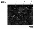
- FIG. 7 shows a mapping image of a secondary battery electrode manufactured in Example 2-1 described later.
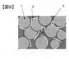
- reference numeral 1 denotes cathode active material particles
- reference numeral 2 denotes a conductive additive made of graphene and fibrous carbon
- reference numeral 3 denotes a void and a binder.
- the data of the current collector is removed from the two-dimensional data of the spreading resistance value, and the data is obtained only for the mixture layer.
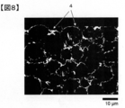
- FIG. 8 shows a binarized image of a secondary battery electrode prepared in Example 2-1 described later.
- Reference numeral 1 in a whitish portion is a positive electrode active material particle
- reference numeral 2 in a grayish color is a conductive additive.
- Reference numeral 3 in the dark portion indicates a void and a binder.
- FIG. 9 shows a model diagram of the mapping image of FIG.
- FIG. 8 is an image obtained by binarizing the mapping image shown in FIG. 7, and a portion (conductive material portion) having a resistance value of 0.7 R or less in FIG. 8 is a white portion indicated by reference numeral 4.
- the binarization process is a process in which a certain threshold value is provided to two-dimensional data, and the two-dimensional data is converted into two gradations (1 or 0) at the threshold value.
- a pixel value indicating a spreading resistance value of 0.7R or less is set to 1 (white), and a pixel value having a spreading resistance value higher than 0.7R is set to 0 (black). I do.
- a binarized image in which the conductive material portion is white and the other portions are black is obtained.
- image conversion software ImageJ free software
- the average aspect ratio of the conductive material portion can be obtained by reading the binarized image obtained as described above into image analysis software and analyzing it.
- image analysis software image analysis type particle size distribution measurement software ⁇ Mac-View ⁇ Ver. It is preferable to have a function of calculating the area, the aspect ratio, the distance between the centers of gravity, the circularity coefficient, and the perimeter as in 4.0.
- an image subjected to the binarization processing is captured, and a conductive material portion is selected.
- the selection of particles is performed by automatic selection.
- the automatic selection is performed with the acquisition mode being color difference, the permissible detection amount being 72 (highest), the detection accuracy being 0.5 (low), the scanning density being 10 (highest density), and the number of scans being three.
- the selection of the conductive material portion is completed by the automatic selection, if a portion where no conductive material portion exists (black portion) is selected, the selection is canceled.
- the scale is set based on the scale bar and the data is registered, whereby the preprocessing is completed, and the image analysis is automatically performed by calling the preprocessing data.
- a conductive material portion having an area of 0.5 ⁇ m 2 or less is excluded from the analysis during the image analysis.
- the average aspect ratio of the conductive material portion in the above-described binarized image reflects the ability to connect between active materials, that is, to maintain a conductive network when used repeatedly, and when it is less than 2.0, when it is repeatedly used. Electronic resistance tends to increase.
- the average aspect ratio is preferably 2.5 or more, more preferably 2.7 or more. Further, if the aspect ratio is too large, the dispersibility becomes worse, and the resistance may rather increase. Therefore, the average aspect ratio is preferably 5.0 or less, more preferably 3.0 or less. .
- the aspect ratio in the present specification refers to a rectangle circumscribing a selected conductive material portion, and when the area is minimized, the longer side of the rectangle is defined as the major axis and the shorter side is defined as the minor axis. It is a value divided by the diameter, and the average value of all the aspect ratios of the selected conductive material portion is defined as the average aspect ratio.
- the value obtained by dividing the average value of the major axis of the conductive material portion in the above-described binarized image by the median diameter of the active material particles for the secondary battery connects the active materials in the same manner as the average aspect ratio, that is, a network when repeatedly used. , And preferably 0.25 or more. When it is less than 0.25, the electronic aid tends to increase when repeatedly used because the conductive auxiliary is shorter than the active material.
- the value is more preferably 0.3 or more, and further preferably 0.35 or more.
- the circularity coefficient of the conductive material portion in the above-described binarized image is preferably 0.20 or less.
- the average value of all the selected conductive material portions is defined as a circularity coefficient.
- the circularity coefficient reflects the degree of agglomeration between the conductive material portions. If it exceeds 0.20, the agglomeration is large, the ratio of the portion where the conductive assistants are agglomerated becomes large, and the electron conduction between the active materials becomes large. The sex worsens.
- the circularity coefficient is more preferably 0.18 or less, and most preferably 0.17 or less.
- the average area of the conductive material portion in the above-described binarized image is less than 1.0 ⁇ m 2 , the electronic resistance as an electrode increases, and when it exceeds 1.6 ⁇ m 2 , the energy density decreases. It is preferably from 0.0% to 1.6 ⁇ m 2 .
- the average distance between the centers of gravity of the conductive material portions in the above-described binarized image is preferably 1.4 ⁇ m or more.
- the distance between the centers of gravity is based on the center of gravity of a certain conductive material portion, and the distance from the center of gravity to the center of gravity of the closest conductive material portion is defined as the distance between the centers of gravity.
- the average value of all the selected conductive material portions is the average distance between the centers of gravity.
- the average distance between the centers of gravity indicates the distance between the conductive material portions in the electrode. If the average center-to-center distance is less than 1.4 ⁇ m, the ratio of the conductive auxiliary agent having a low aspect ratio segregating becomes large, and the space is repeatedly used to form a void. When this happens, the electronic resistance increases.
- the distance between the centers of gravity is preferably 1.7 or more, and most preferably 1.9 or more.
- the circularity coefficient, the average area, and the average distance between the centers of gravity of the conductive material portions can be obtained by image analysis using the same binary image image analysis software as that for obtaining the above-mentioned aspect ratio.
- the ratio of the average circularity coefficient of the particles having an area of less than 0.5 ⁇ m 2 to the average circularity coefficient of the particles having an area of 0.5 ⁇ m 2 or more may be 1.50 or more. preferable.
- the portion having a small area and a high circularity coefficient has a role of forming a long-distance conductive path from the surface of the electrode to the current collector foil.
- the average circularity coefficient of particles having a particle size of less than 5 ⁇ m 2 increases.
- a portion having a large area and a small circularity coefficient has a role of forming a short-distance conductive path such as active material particles and conductive assistants.
- the average circularity coefficient of the particles having a size of 0.5 ⁇ m 2 or more is small.
- the ratio of these circularity coefficients indicates the degree to which graphene and fibrous carbon are well dispersed, and it has been found that a strong conductive network can be formed by setting the ratio to 1.50 or more. If the circularity coefficient ratio is less than 1.50, one of them is agglomerated, the roles of the short-range and long-distance conductive paths cannot be shared, and a strong conductive network cannot be formed. The life is shortened.
- the electrode for a secondary battery of the present invention typically has the above-mentioned mixture layer formed on a current collector.
- a metal foil or a metal mesh is preferably used as the current collector.
- an aluminum foil is preferably used for the positive electrode, and a copper foil is preferably used for the negative electrode.
- the electrode for a secondary battery of the present invention can be produced, for example, by preparing a graphene dispersion liquid and a fibrous carbon dispersion liquid described below, and then performing an electrode forming step described below.
- Graphene dispersion used in the present invention, as an example, A surface treatment step of mixing graphene oxide and a surface treatment agent having an acidic group in a solvent; A reduction step of reducing graphene oxide dispersed in a dispersion medium containing water; An organic solvent mixing step of mixing the intermediate dispersion having undergone the reduction step with an organic solvent; A strong stirring step of stirring the intermediate dispersion liquid containing an organic solvent at a peripheral speed of the rotary blade of the mixer of 6 m / s or more and 70 m / s or less; Can be produced by a production method including: Further, a cleaning step and a miniaturization step described below may be provided.
- the average circularity coefficient, the circularity coefficient ratio, the average aspect ratio, and the average distance between the centers of gravity of the particles having the above-mentioned area of 0.5 ⁇ m 2 or more are preferably set as described above. Can be easily adjusted to the range.
- graphene oxide There is no particular limitation on a method for manufacturing graphene oxide, and a known method such as a Hummers method can be used. Alternatively, commercially available graphene oxide may be purchased.
- Graphene oxide has high dispersibility, but is itself insulating and cannot be used as a conductive additive or the like. If the degree of oxidation of the graphene oxide is too high, the conductivity of the graphene powder obtained by reduction may deteriorate, so that the ratio of the carbon atoms to the oxygen atoms of the graphene oxide measured by X-ray photoelectron spectroscopy is as follows: It is preferably 0.5 or more. When measuring graphene oxide by X-ray photoelectron spectroscopy, the measurement is performed in a state where the solvent is sufficiently dried.
- the degree of oxidation of graphene oxide can be adjusted by changing the amount of oxidizing agent used for the oxidation reaction of graphite. Specifically, the higher the amount of sodium nitrate and potassium permanganate with respect to graphite used in the oxidation reaction, the higher the degree of oxidation, and the lower the amount, the lower the degree of oxidation.
- the weight ratio of sodium nitrate to graphite is not particularly limited, but is preferably 0.200 or more and 0.800 or less, more preferably 0.250 or more and 0.500 or less, and 0.275 or more. More preferably, it is 0.425 or less.
- the ratio of potassium permanganate to graphite is not particularly limited, but is preferably 1.00 or more, more preferably 1.40 or more, even more preferably 1.65 or more. Moreover, it is preferably 4.00 or less, more preferably 3.00 or less, and further preferably 2.55 or less.
- the graphene oxide is mixed with a surface treatment agent having an acidic group.
- the surface treatment agent exhibits an effect of increasing the dispersibility of graphene by being present at least in part on the surface of graphene, and is particularly effective for good dispersion of graphene in an organic solvent. This is important for forming a conductive network connecting the active materials in the final mixture layer.
- the acidic group is a hydroxy group, a phenolic hydroxy group, a nitro group, a carboxyl group, or a carbonyl group.
- the surface treating agent is not particularly limited as long as it is a compound having an acidic group, that is, a hydroxy group, a phenolic hydroxy group, a nitro group, a carboxyl group, or a carbonyl group, but a low molecular weight compound is preferred.
- a compound having a catechol group is preferable as a surface treatment agent because it has adhesiveness to graphene and dispersibility in a solvent.
- the compound having a catechol group include catechol, dopamine hydrochloride, 3- (3,4-dihydroxyphenyl) -L-alanine, 4- (1-hydroxy-2-aminoethyl) catechol, and 3,4-dihydroxybenzoic acid , 3,4-dihydroxyphenylacetic acid, caffeic acid, 4-methylcatechol and 4-tert-butylpyrocatechol.
- the surface treating agent may have a basic group in addition to the acidic group.
- the surface treating agent has an amino group to improve dispersibility. Therefore, a compound having both a catechol group and an amino group is particularly preferable as a surface treatment agent. Examples of such a compound include dopamine hydrochloride.
- the solvent used in the reduction step is preferably a polar solvent, such as water, ethanol, methanol, 1-propanol, 2-propanol, N-methylpyrrolidone, dimethylformamide, dimethylacetamide, dimethylsulfoxide, ⁇ -butyrolactone, or a mixture of the above.
- a polar solvent such as water, ethanol, methanol, 1-propanol, 2-propanol, N-methylpyrrolidone, dimethylformamide, dimethylacetamide, dimethylsulfoxide, ⁇ -butyrolactone, or a mixture of the above.
- the above-described surface treatment agent mixing step is performed in a solvent, the state after the completion of the step may be directly transferred to the reduction step, or may be diluted with the same solvent as the solvent used in the surface treatment agent mixing step. It is preferred to reduce.
- the method of reducing graphene oxide is not particularly limited, but chemical reduction is preferred.
- examples of the reducing agent include an organic reducing agent and an inorganic reducing agent, and an inorganic reducing agent is more preferable because of ease of washing after reduction.
- sodium dithionite, potassium dithionite, phosphorous acid, sodium borohydride, hydrazine and the like among which sodium dithionite and potassium dithionite, while relatively retaining an acidic group Since it can be reduced, graphene having high dispersibility in a solvent can be produced and is preferably used.
- miniaturization process Before, during, or during the reduction step, it is preferable to perform a miniaturization step of miniaturizing graphene oxide or reduced graphene contained in the intermediate dispersion before, during, or during the reduction step.
- the reduction step In order to obtain the graphene dispersion liquid used in the present invention, it is preferable to perform the reduction step in a state where the graphene oxide is refined. Therefore, the refinement step may be performed before the reduction step or during the reduction step. preferable.
- the size of graphene oxide or graphene in the plane direction can be made appropriate.
- the preferred size is as described above.
- the technique for making the particles fine it is obtained by mixing a plurality of grinding media such as beads and balls with a dispersion and causing the grinding media to collide with each other.
- a method of colliding a pressure-applied intermediate dispersion with a single ceramic ball, or a method of using a liquid-liquid shear-type wet jet mill that collides and disperses a pressure-applied intermediate dispersion with each other can be mentioned.
- a method of applying ultrasonic waves to the intermediate dispersion liquid is also a medialess dispersion method, and is a preferable method.
- graphene oxide or graphene tends to be miniaturized as the processing pressure or output in the medialess dispersion method increases, and as the processing time increases, the graphene tends to miniaturize.
- the preferred size of the graphene in the plane direction is as described above.
- the size of reduced graphene can be adjusted by the type, processing conditions, and processing time of the miniaturization treatment in the miniaturization step.
- Organic solvent mixing step In the organic solvent mixing step, the intermediate dispersion liquid and the organic solvent are mixed in order to replace water in the intermediate dispersion liquid after the reduction step with an organic solvent.
- the organic solvent mixing step the intermediate dispersion liquid obtained through the surface treatment step and the reduction step, or the intermediate dispersion liquid further subjected to a washing step and / or a miniaturization step as needed, and an organic solvent Mix directly. That is, from the end of the reduction step to the mixing with the organic solvent in the organic solvent mixing step, the intermediate dispersion is always in a dispersion state, and the dispersion medium is removed from the intermediate dispersion to recover graphene in a powder state. No operation such as freeze-drying is performed.
- a step of stirring the intermediate dispersion liquid containing the organic solvent at a peripheral speed of the rotary blade of the mixer of 6 m / s or more and 70 m / s is performed.
- Exfoliation of graphene in the strong stirring process can eliminate the stack of graphene, which is particularly effective for good dispersion of graphene in an organic solvent, and is a conductive material that connects active materials in the final mixture layer. It is important for network formation.
- a rotary blade mixer capable of giving such a strong stirring force to the intermediate dispersion liquid is referred to as a “strong stirring mixer”.
- the peripheral speed of the rotary blade of the mixer is preferably 10 m / s or more, more preferably 30 m / s or more.
- the peripheral speed of the rotary blade of the mixer is defined by peripheral length ⁇ rotation speed. If the peripheral speed is too low, peeling of graphene hardly occurs, and the degree of peeling of graphene decreases. On the other hand, if the peripheral speed is too high, the degree of peeling of graphene becomes too high, and the dispersibility decreases.
- the shear rate is more preferably 5,000 to 50,000 per second. If the shear rate is too low, peeling of graphene hardly occurs, and the degree of peeling of graphene decreases. On the other hand, if the shear rate is too high, the exfoliation degree of graphene becomes too high, and the dispersibility decreases.
- the shear rate is a value obtained by dividing the peripheral speed at the maximum diameter of the rotary blade of the mixer by the distance from the wall surface of the tip of the mixer rotary blade (the cutting edge that determines the maximum diameter).
- the processing time of the strong stirring step is preferably 15 seconds to 300 seconds, more preferably 20 seconds to 120 seconds, and still more preferably 30 seconds to 80 seconds.
- a planetary mixer with a disper or a device capable of obtaining a high peripheral speed such as robomix is preferable.
- the distance between the rotating blade and the wall surface such as a thin film turning method or a rotor / stator method is preferable.
- a mixer having a short shape of 10 mm or less and having a high shear force of a medialess system is more preferable.
- mixers having such a high shearing force for example, Fillmix (registered trademark) 30-30 type (manufactured by Primix), CLEARMIX (registered trademark) CLM-0.8S (manufactured by M Technic), Supershare And a mixer SDRT 0.35-0.75 (manufactured by Satake Chemical Machinery Co., Ltd.).
- Fillmix registered trademark
- CLEARMIX registered trademark
- CLM-0.8S manufactured by M Technic
- Supershare And a mixer SDRT 0.35-0.75 manufactured by Satake Chemical Machinery Co., Ltd.
- the solid content of the graphene dispersion is preferably 3.0% by mass or more and 20% by mass or less.
- the solid content is more preferably 10% by mass or less, and further preferably 5.0% by mass or less.
- the solid content rate is more preferably 3.0% by mass or more, and further preferably 4.0% by mass or more.
- the solid content of the graphene dispersion can be calculated by measuring the mass after drying the solvent from the graphene dispersion and dividing the measured value by the mass of the graphene dispersion itself. Specifically, about 1 g of a graphene dispersion liquid is adhered on a glass substrate having a known mass, and heated on a hot plate adjusted to a temperature of 120 ° C. for 1.5 hours to volatilize the solvent, and the mass of the graphene remaining when the solvent is volatilized. Is measured.
- Fibrous carbon dispersion As an example of a method for obtaining a fibrous carbon dispersion, a method in which fibrous carbon powder is directly mixed with an organic solvent is exemplified. At this time, it is preferable to use a dispersant.
- the dispersant include those exemplified as the dispersant contained in the mixture layer.
- the stirring processing is performed at a peripheral speed of the rotary blade of the mixer of 6 m / s or more and 70 m / s.
- the average circularity coefficient and the circularity coefficient ratio of the particles whose area is less than 0.5 ⁇ m 2 , and the average distance between the centers of gravity are within the above-described preferred ranges. It can be easily adjusted.
- a fibrous carbon dispersion having a solid content of 2.0% by mass or more and 20% by mass or less.
- the solid content is preferably 10% by mass or less, more preferably 5.0% by mass or less. Further, the solid content is preferably at least 3.0% by mass, more preferably at least 4.0% by mass.
- the solid content is 2.0% by mass or more, a shearing force is easily applied to the fibrous carbon during strong stirring, and the aggregated fibrous carbon can be easily loosened.
- the solid content is 20% by mass or less, the aggregation of the fibrous carbon in the dispersion is suppressed, and the viscosity is appropriately reduced, and strong stirring is easily performed. it can.
- Electrode conversion step As a first embodiment, after the active material particles and the above-described graphene dispersion liquid are strongly stirred at a peripheral speed of a rotary blade of a mixer of 6 m / s or more and 70 m / s or less, a binder solution of 5 mass% or more and 20 mass% or less is used. After that, the above-mentioned fibrous carbon dispersion liquid is subjected to a strong stirring treatment at a peripheral speed of the rotary blade of the mixer of 6 m / s or more and 70 m / s or less.
- An electrode paste is prepared so as to have a concentration of 65% by mass to 75% by mass, applied to a current collector foil, dried, and then pressed using a press machine, whereby an electrode for a secondary battery can be manufactured.
- the above-mentioned fibrous carbon dispersion is mixed with a mixer.
- a binder solution of 5.0 mass% or more and 20 mass% or less and an appropriate amount of a solvent are added as necessary, and the solid content concentration is 65%.
- An electrode paste is prepared so as to have a concentration of from 75% by mass to 75% by mass, applied to a current collector foil, dried, and then pressed by using a press machine to produce an electrode for a secondary battery.
- the graphene dispersion liquid and the carbon nanotube dispersion liquid are dried once before preparing the electrode paste, the cohesion becomes stronger, and therefore, it is important to perform the drying without drying to form a conductive network in the final mixture layer.
- the graphene dispersion liquid and the active material particles are subjected to strong stirring at a high concentration to apply a shearing force to the graphene and to promote the exfoliation. Therefore, the active material particles in the final mixture layer are further promoted. This is effective for forming a conductive network that connects them.
- the binder described above can be used. It is preferable that the binder is used after being dissolved in a solvent in advance.
- the solvent to be used include NMP, ⁇ -butyrolactone, water, dimethylacetamide and the like, and it is most preferable to use NMP which is a solvent contained in the graphene dispersion used in the present invention.
- the concentration of the binder solution is preferably 3% by mass or more and 20% by mass or less, more preferably 5% by mass or more and 10% by mass or less. If the concentration is too low, it is difficult to apply a shearing force to the graphene during strong stirring, and it becomes difficult to peel off. If the concentration is too high, the viscosity becomes too high, so that strong stirring cannot be performed, and it is difficult to maintain a good dispersion state.
- the secondary battery of the present invention includes the above-described electrode for a secondary battery, and preferably further includes a separator, an electrolyte, and an exterior member.
- the negative electrode can include a negative electrode current collector and a negative electrode active material-containing layer.
- the negative electrode active material-containing layer can be formed on one side or both sides of the negative electrode current collector.
- the negative electrode active material containing layer contains a negative electrode active material and can further contain a conductive agent and a binder.
- the negative electrode active material examples include lithium metals and lithium alloys; carbon-based active materials such as coke, artificial graphite, natural graphite, organic polymer compound burners, and carbon fibers; lithium such as Si, SiO x , Sn or SnO 2. And alloy-based active materials; such as titanium oxide, lithium titanium oxide, niobium titanium oxide, and sodium niobium titanium oxide. Two or more of these may be used. A carbon coat or an electron-conductive inorganic material coat may be applied to the surface of the negative electrode active material particles.
- the conductive agent is blended in order to enhance the current collecting performance and suppress the contact resistance between the negative electrode active material and the current collector.
- the conductive agent include carbon materials such as carbon nanotubes, acetylene black, carbon black, and graphite. Two or more of these may be used. Further, graphene or fibrous carbon with improved dispersibility described in the above electrode may be used.
- the binder is blended to fill gaps between the dispersed negative electrode active materials and to bind the negative electrode active material and the negative electrode current collector.
- the binder include polytetrafluoroethylene (PTFE), polyvinylidene fluoride (PVDF), fluorine-based rubber, styrene-butadiene rubber, polyacrylic acid compound, imide compound and the like. Two or more of these may be used.
- the active material, the conductive agent, and the binder in the negative electrode active material-containing layer are mixed at a ratio of 68% by mass or more and 96% by mass or less, 2% by mass or more and 30% by mass or less, and 2% by mass or more and 30% by mass or less. Is preferred.
- the negative electrode current collector is preferably made of copper, nickel, stainless steel, or aluminum, or an aluminum alloy containing one or more elements selected from Mg, Ti, Zn, Mn, Fe, Cu, and Si.
- the thickness of the negative electrode current collector is preferably in the range of 5 ⁇ m or more and 20 ⁇ m or less.
- the negative electrode can be produced, for example, by the following method. First, a negative electrode active material, a conductive agent and a binder are suspended in a solvent to prepare a slurry. This slurry is applied to one or both surfaces of the negative electrode current collector. Next, the applied slurry is dried to obtain a laminate of the negative electrode active material-containing layer and the negative electrode current collector. Thereafter, the laminate is pressed. Thus, a negative electrode is manufactured.
- the negative electrode may be manufactured by the following method. First, a negative electrode active material, a conductive agent, and a binder are mixed to obtain a mixture. Next, this mixture is formed into a pellet. Next, a negative electrode can be obtained by disposing these pellets on the negative electrode current collector.
- a liquid non-aqueous electrolyte As the electrolyte, a liquid non-aqueous electrolyte, a gel non-aqueous electrolyte, a room-temperature molten salt (ionic melt) containing lithium ions, a polymer solid electrolyte, an inorganic solid electrolyte, or the like can be used.
- the liquid non-aqueous electrolyte is prepared by dissolving an electrolyte such as LiPF6 in an organic solvent.
- the concentration of the electrolyte is preferably 0.5 mol / L or more and 5.0 mol / L or less.
- the gelled non-aqueous electrolyte is prepared by compounding a liquid non-aqueous electrolyte and a polymer material.
- the polymer material include polyvinylidene fluoride (PVDF), polyacrylonitrile (PAN), polyethylene oxide (PEO), and the like. Two or more of these may be used.
- Normal molten salt refers to a compound that can exist as a liquid at ordinary temperature (15 ° C. or more and 25 ° C. or less) among organic salts composed of a combination of organic cations and anions. Generally, the melting point of the room temperature molten salt used for the nonaqueous electrolyte battery is 25 ° C. or less.
- the organic cation generally has a quaternary ammonium skeleton.
- a polymer solid electrolyte is prepared by dissolving an electrolyte in a polymer material and solidifying it.
- the inorganic solid electrolyte is a solid substance having Li ion conductivity.
- Separator As the separator, it is preferable to use a porous film formed of polyethylene or polypropylene. This is because these porous films can be melted at a certain temperature and interrupt current.
- Exterior members for example, a container made of a laminated film or a metal container can be used.
- the shape of the exterior member is not particularly limited.
- the shape of the exterior member may be, for example, a flat type (thin type), a square type, a cylindrical type, a coin type, a button type, or the like.
- binarization processing was performed on all the two-dimensional data with 0.7R as a threshold.
- a pixel value indicating a resistance value of 0.7R or less is set to 1 (white)
- a pixel value having a resistance value higher than 0.7R is set to 0 (black)
- a binary image (white) is obtained by using ImageJ (free software).
- ImageJ free software
- Image analysis was performed on the obtained conductive material portion.
- image analysis type particle size distribution measurement software ⁇ Mac-View ⁇ Ver. Using 4.0 °, this was performed under the following automatic selection conditions.
- the acquisition mode was color difference, the permissible detection amount was 72 (highest), the detection accuracy was 0.5 (sweet), the scanning density was 10 (highest density), and the number of scans was three, and particles were automatically selected. Then, set the scale based on the scale bar mapping image, performs image analysis software, the average aspect ratio, average circularity coefficient less than the area 0.5 [mu] m 2, the area 0.5 [mu] m 2 or more average circularity coefficient, The average distance between the centers of gravity and the average major axis were obtained.
- a washing step of filtering with a reduced pressure suction filter, further diluting with water to 0.5% by mass, and performing suction filtration was repeated five times to wash.
- the mixture was diluted with NMP to 0.5% by mass, and treated with Fillmix (trademark) type 30-30 (Primix) at a peripheral speed of 40 m / s (shear speed: 40,000 per second) for 60 seconds (strong stirring step). ) And filtered with suction.
- the step of diluting with NMP to 0.5% by mass, treating with a homodisper 2.5 type (Primix) at a rotation speed of 3000 RPM for 30 minutes, and performing suction filtration is repeated four times to obtain a graphene NMP dispersion. Obtained.
- NMP was added to adjust the concentration of the dispersion to 4.0% by mass, and the dispersion was treated at a rotation speed of 20 RPM for 30 minutes using a planetary mixer.
- a graphene NMP dispersion (4.0% by mass) was obtained.
- NMP was added to the graphene powder, the concentration of the dispersion was adjusted to 2.0% by mass, and the mixture was treated at a rotation speed of 20 RPM for 30 minutes using a planetary mixer to obtain a graphene NMP dispersion (2.0% by mass). .
- Synthesis Example 5 Method for Preparing Graphene NMP Dispersion 4
- a graphene NMP dispersion (4.0% by mass) was obtained in the same manner as in Synthesis Example 2 except that the ultrasonic treatment device was not used.
- Example 1-1 0.5 parts by weight of the graphene dispersion liquid (4.0% by mass) prepared in Synthesis Example 2 as a conductive auxiliary agent as a graphene solid content, and polyvinylidene fluoride # 7200 (manufactured by Kureha Corporation) as a binder solid content of 1 part Then, the mixture was treated for 60 seconds at a peripheral speed of 40 m / s (shear speed: 40,000 per second) using Fillmix (registered trademark) Model 30-30 (Primix). The binder used herein was previously dissolved in NMP to form an 8.0% by mass solution.
- NCM LiNi 0.5 Co 0.2 Mn 0.3 O 2
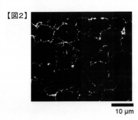
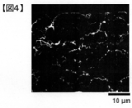
- FIGS. 1 and 2 show the spread resistance value distribution image (mapping image) and the binarized image before binarization obtained by the method of Measurement Example 1 for the electrode plate.
- Example 1-2 The graphene dispersion (4.0% by mass) prepared in Synthesis Example 2 as a conductive aid was 0.25 parts by weight as a graphene solid, and the graphene dispersion (4.0% by mass) prepared in Synthesis Example 5 was graphene solid. 0.25 parts by weight as a binder, 1.0 part by weight of polyvinylidene fluoride # 7200 (manufactured by Kureha Co.) as a binder, and NMP as a solvent were added in a total amount of 43 parts by weight.
- An electrode plate was produced under the same conditions as in Example 1 except that it was added.
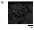
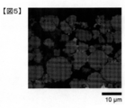
- FIGS. 3 and 4 show the spread resistance value distribution image (mapping image) and the binarized image before binarization obtained by the method of Measurement Example 1 for the electrode plate.
- Example 1-3 1.0 parts by weight of the graphene dispersion liquid (4.0% by mass) prepared in Synthesis Example 2 as a conductive aid was used as a graphene solid content, and polyvinylidene fluoride # 7200 (manufactured by Kureha Co., Ltd.) was used as a binder.
- An electrode plate was produced under the same conditions as in Example 1-1, except that 0 parts by weight was used and NMP was additionally added as a solvent so that the total amount became 50 parts by weight.
- Example 1-4 0.2 parts by weight of the graphene dispersion liquid (4.0% by mass) prepared in Synthesis Example 2 as a conductive aid was used as a graphene solid, and polyvinylidene fluoride # 7200 (manufactured by Kureha Co., Ltd.) was used as a binder.
- An electrode plate was prepared under the same conditions as in Example 1-1, except that 0 parts by weight was used and NMP was additionally added as a solvent so that the total amount became 40 parts by weight.
- Example 1-5 0.5 parts by weight of the graphene dispersion liquid (3.0% by mass) prepared in Synthesis Example 6 as a conductive auxiliary agent as a graphene solid content, and LiNi 0.5 Co 0.2 Mn 0.3 O 2 as active material particles (NCM) (100 parts by weight of granules having a median diameter of 10 ⁇ m is added, and the mixture is treated for 60 seconds at a peripheral speed of 40 m / s (shear speed: 40,000 per second) using Fillmix (registered trademark) Model 30-30 (Primix).
- NCM active material particles
- the mixture was mixed at a rotation speed of 30 RPM for 30 minutes using a planetary mixer, and then 1.0 part by weight of polyvinylidene fluoride # 7200 (manufactured by Kureha Co.) as a binder was added as a binder solid content, and NMP was used as a solvent in a total amount of 45 parts by weight. Parts by weight, and then mixed for 30 minutes at a rotation speed of 15 RPM using a planetary mixer to mix the electrode paste.
- the electrode paste was prepared by previously dissolving the binder in NMP to form a 5.0% by mass solution on an aluminum foil (thickness: 18 ⁇ m) using a doctor blade to give a basis weight of 15 mg / cm 2. After drying at 80 ° C. for 30 minutes, the resultant was pressed with a roll press machine, and vacuum dried using a vacuum dryer at 120 ° C. for 5 hours to obtain an electrode plate. Was 40 ⁇ m in thickness.
- the binder was used by previously dissolving it in NMP to form a 5% by mass solution.
- FIGS. 5 and 6 show the spread resistance value distribution image (mapping image) and the binarized image before binarization obtained by the method of Measurement Example 1 for the electrode plate.
- Example 1-2 An electrode was prepared in the same manner as in Example 1-1, except that the graphene dispersion prepared in Synthesis Example 3 was used as a conductive additive, and NMP was additionally added as a solvent so that the total amount became 48 parts by weight. did.
- Example 1-3 An electrode was prepared in the same manner as in Example 1-1, except that the graphene dispersion prepared in Synthesis Example 4 was used as a conductive additive, and NMP was additionally added as a solvent to a total amount of 61 parts by weight. did.
- Example 1-4 An electrode was prepared in the same manner as in Example 1-1, except that the graphene dispersion prepared in Synthesis Example 2 was used as a conductive additive, and NMP was additionally added as a solvent so that the total amount became 60 parts by weight. did.
- Example 1-5 An electrode was prepared in the same manner as in Example 1-1, except that the graphene dispersion prepared in Synthesis Example 2 was used as a conductive additive, and NMP was additionally added as a solvent to a total amount of 70 parts by weight. did.
- the average circularity coefficient having an area of less than 0.5 ⁇ m 2 , the average circularity coefficient having an area of 0.5 ⁇ m 2 or more, and the average circularity obtained by subjecting the electrodes produced in each of the examples and comparative examples to image analysis by the method of Measurement Example 1 Tables 1 and 2 summarize the battery ratio evaluation results by the coefficient ratio, average aspect ratio, average center-of-gravity distance, average major axis / active material median diameter, and the method of Measurement Example 2.
- Example 2-1 Graphene dispersion liquid 1 (4.0% by mass) prepared in Synthesis Example 2 as a conductive additive was 0.5 parts by mass as a graphene solid content, and LiNi 0.5 Co 0.2 Mn 0.3 O was used as active material particles. 100 parts by mass of 2 (NCM) (manufactured by Umicore, granules having a median diameter of 10 ⁇ m) were added, and mixed at a rotation speed of 30 RPM for 30 minutes using a planetary mixer.
- NCM manufactured by Umicore, granules having a median diameter of 10 ⁇ m
- the electrode paste was obtained using “Fillmix” (registered trademark) Model 30-30 (Primix) at a peripheral speed of 40 m / s (shear speed: 40,000 per second) for 60 seconds.
- This electrode paste was applied to an aluminum foil (thickness: 18 ⁇ m) using a doctor blade so as to have a basis weight of 1.5 mg / cm 2 , dried at 80 ° C. for 30 minutes, pressed by a roll press, and dried by a vacuum dryer. The resultant was vacuum-dried at 120 ° C. for 5 hours to obtain an electrode.
- the thickness of the electrode mixture layer (excluding the aluminum foil) was 40 ⁇ m.
- FIGS. 7 and 8 show the spread resistance value distribution image (mapping image) and the binarized image before binarization obtained by the method of Measurement Example 1 for the electrodes.
- Example 2-2 0.15 parts by mass of the graphene dispersion liquid 1 (4.0% by mass) prepared in Synthesis Example 2 as a conductive assistant was 0.15 parts by mass as a graphene solid content, and 0.1% by mass of the fibrous carbon dispersion liquid 1 prepared in Synthesis Example 7 as a solid content.
- An electrode was produced under the same conditions as in Example 2-1 except that 35 parts by mass and NMP as a solvent were additionally added so as to be a total amount of 30 parts by mass.
- Example 2-3 Graphene dispersion liquid 1 (4.0% by mass) prepared in Synthesis Example 2 was 0.35 parts by mass as a graphene solid content, and fibrous carbon dispersion liquid 1 prepared in Synthesis Example 7 was 0.1% by mass as a conductive auxiliary.
- An electrode was produced under the same conditions as in Example 2-1 except that 15 parts by mass and NMP as a solvent were additionally added so as to be a total amount of 33 parts by mass.
- Example 2-4 Graphene dispersion liquid 1 (4.0% by mass) prepared in Synthesis Example 2 as a conductive aid was 0.25 parts by mass as a graphene solid content, and fibrous carbon dispersion liquid 1 prepared in Synthesis Example 7 was 0.1% as a solid content.
- An electrode was produced under the same conditions as in Example 2-1 except that 25 parts by mass and NMP as a solvent were additionally added so as to be a total amount of 32 parts by mass.
- Example 2-5 Graphene dispersion liquid 1 (4.0% by mass) prepared in Synthesis Example 2 as a conductive assistant was 0.5 parts by mass as a graphene solid content, and fibrous carbon dispersion liquid 2 (4.0% by mass) prepared in Synthesis Example 8 ) was added under the same conditions as in Example 2-1 except that 0.5 parts by mass as solid content and NMP as a solvent were further added so as to be 50 parts by mass in total.
- Example 2-6 Graphene dispersion 3 (4.0% by mass) prepared in Synthesis Example 4 as a conductive aid was 0.25 parts by mass as a graphene solid content, and fibrous carbon dispersion liquid 1 prepared in Synthesis Example 7 was 0.2% by mass as a solid content.
- An electrode was produced under the same conditions as in Example 2-1 except that 25 parts by mass and NMP as a solvent were additionally added so as to be a total amount of 33 parts by mass.
- Example 2-7 Graphene dispersion liquid 1 (4.0% by mass) prepared in Synthesis Example 2 as a conductive assistant was 0.25 parts by mass as a graphene solid content, and fibrous carbon dispersion liquid 3 prepared in Synthesis Example 9 was 0.1% as a solid content.
- An electrode was produced under the same conditions as in Example 2-1 except that 25 parts by mass and NMP as a solvent were additionally added so as to be a total amount of 31 parts by mass.
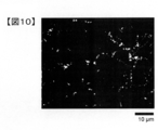
- FIG. 10 shows a binarized image of the electrode plate obtained by the method of Measurement Example 1.
- NMP was additionally added as a solvent so as to have a total amount of 35 parts by mass, and then mixed at a rotation speed of 1.5 RPM for 30 minutes using a planetary mixer to obtain an electrode paste.
- the electrode paste is applied to an aluminum foil (thickness: 18 ⁇ m) using a doctor blade, dried at 80 ° C. for 30 minutes, pressed by a roll press, and vacuum dried at 120 ° C. for 5 hours using a vacuum dryer. An electrode was obtained.
- the thickness of the electrode mixture layer (excluding the aluminum foil) was 40 ⁇ m.
- Example 2 except that the graphene dispersion liquid 2 (4.0% by mass) prepared in Synthesis Example 3 was used as a conductive additive and NMP was additionally added as a solvent so that the total amount became 50 parts by mass.
- An electrode plate was produced under the same conditions as in -1.
- the average circularity coefficient having an area of less than 0.5 ⁇ m 2 , the average circularity coefficient having an area of 0.5 ⁇ m 2 or more, and the average were obtained by performing image analysis on the electrodes prepared in each of the Examples and Comparative Examples by the method of Measurement Example 1.
- Tables 3 and 4 summarize the battery performance evaluation results by the ratio of the circularity coefficient, the average aspect ratio, the average distance between the centers of gravity, the average major axis / active material median diameter, and the method of Measurement Example 2.
Landscapes
- Chemical & Material Sciences (AREA)
- Chemical Kinetics & Catalysis (AREA)
- Electrochemistry (AREA)
- General Chemical & Material Sciences (AREA)
- Engineering & Computer Science (AREA)
- Materials Engineering (AREA)
- Inorganic Chemistry (AREA)
- Organic Chemistry (AREA)
- Manufacturing & Machinery (AREA)
- Nanotechnology (AREA)
- Battery Electrode And Active Subsutance (AREA)
Abstract
Priority Applications (5)
| Application Number | Priority Date | Filing Date | Title |
|---|---|---|---|
| EP19859334.5A EP3852168A4 (fr) | 2018-09-10 | 2019-09-06 | Électrode pour batterie secondaire et batterie secondaire |
| US17/269,643 US20210305576A1 (en) | 2018-09-10 | 2019-09-06 | Electrode for secondary battery and secondary battery |
| CN201980057230.2A CN112640155A (zh) | 2018-09-10 | 2019-09-06 | 二次电池用电极及二次电池 |
| KR1020217005510A KR102276630B1 (ko) | 2018-09-10 | 2019-09-06 | 이차 전지용 전극 및 이차 전지 |
| JP2019549598A JP6760512B1 (ja) | 2018-09-10 | 2019-09-06 | 二次電池用電極および二次電池 |
Applications Claiming Priority (4)
| Application Number | Priority Date | Filing Date | Title |
|---|---|---|---|
| JP2018-168778 | 2018-09-10 | ||
| JP2018168778 | 2018-09-10 | ||
| JP2019045449 | 2019-03-13 | ||
| JP2019-045449 | 2019-03-13 |
Publications (1)
| Publication Number | Publication Date |
|---|---|
| WO2020054615A1 true WO2020054615A1 (fr) | 2020-03-19 |
Family
ID=69777986
Family Applications (1)
| Application Number | Title | Priority Date | Filing Date |
|---|---|---|---|
| PCT/JP2019/035201 Ceased WO2020054615A1 (fr) | 2018-09-10 | 2019-09-06 | Électrode pour batterie secondaire et batterie secondaire |
Country Status (6)
| Country | Link |
|---|---|
| US (1) | US20210305576A1 (fr) |
| EP (1) | EP3852168A4 (fr) |
| JP (1) | JP6760512B1 (fr) |
| KR (1) | KR102276630B1 (fr) |
| CN (1) | CN112640155A (fr) |
| WO (1) | WO2020054615A1 (fr) |
Cited By (5)
| Publication number | Priority date | Publication date | Assignee | Title |
|---|---|---|---|---|
| JP2022158015A (ja) * | 2021-04-01 | 2022-10-14 | 株式会社デンソー | ヒータ材およびその製造方法 |
| JP2023004911A (ja) * | 2021-06-25 | 2023-01-17 | 東レ株式会社 | 素子およびその製造方法ならびに電子デバイスおよび無線通信装置 |
| JP2023034038A (ja) * | 2021-08-30 | 2023-03-13 | 本田技研工業株式会社 | 解析装置、解析方法、およびプログラム |
| WO2023074293A1 (fr) * | 2021-10-28 | 2023-05-04 | 日本ゼオン株式会社 | Dispersion de matériau conducteur pour batteries secondaires, bouillie pour électrodes de batterie secondaire, électrode pour batteries secondaires et batterie secondaire |
| CN116325046A (zh) * | 2020-11-27 | 2023-06-23 | 日本瑞翁株式会社 | 电化学元件用糊、电化学元件电极用浆料、电化学元件用电极和电化学元件 |
Families Citing this family (2)
| Publication number | Priority date | Publication date | Assignee | Title |
|---|---|---|---|---|
| EP4318651A4 (fr) * | 2021-03-31 | 2025-08-13 | Panasonic Ip Man Co Ltd | Dispersion liquide de matériau conducteur, pâte d'électrode positive pour batterie secondaire à électrolyte non aqueux, électrode positive pour batterie secondaire à électrolyte non aqueux et batterie secondaire à électrolyte non aqueux |
| US12482811B2 (en) * | 2021-03-31 | 2025-11-25 | Panasonic Intellectual Property Management Co., Ltd. | Positive electrode for nonaqueous-electrolyte secondary battery and nonaqueous-electrolyte secondary battery using same |
Citations (7)
| Publication number | Priority date | Publication date | Assignee | Title |
|---|---|---|---|---|
| JP2012014838A (ja) | 2010-06-29 | 2012-01-19 | Hitachi Ltd | 非水電解質二次電池 |
| JP2015215947A (ja) | 2014-05-07 | 2015-12-03 | 株式会社カネカ | 非水電解質二次電池用電極及び非水電解質二次電池 |
| WO2016050895A1 (fr) | 2014-10-02 | 2016-04-07 | Fraunhofer-Gesellschaft zur Förderung der angewandten Forschung e.V. | Dispositif et procédé de détermination d'un indice de réfraction |
| WO2017047523A1 (fr) * | 2015-09-18 | 2017-03-23 | 東レ株式会社 | Dispersion de graphène, son procédé de production, procédé de production de particules de composite graphène/matériau actif, et procédé de production de pâte d'électrode |
| WO2017061323A1 (fr) * | 2015-10-05 | 2017-04-13 | 東レ株式会社 | Électrode positive pour batterie secondaire au lithium-ion, particules composites de matière active d'électrode positive/graphène, et leurs procédés de fabrication, et pâte d'électrode positive pour batterie secondaire au lithium-ion |
| JP2017218373A (ja) * | 2016-06-06 | 2017-12-14 | 東レ株式会社 | グラフェン/有機溶媒分散液、グラフェン−活物質複合体粒子の製造方法および電極ペーストの製造方法 |
| JP2018160418A (ja) | 2017-03-23 | 2018-10-11 | 株式会社東芝 | 電極、二次電池、電池パック及び車両 |
Family Cites Families (13)
| Publication number | Priority date | Publication date | Assignee | Title |
|---|---|---|---|---|
| KR101267351B1 (ko) * | 2007-12-25 | 2013-05-24 | 가오 가부시키가이샤 | 리튬전지 양극용 복합재료 |
| TWI405802B (zh) * | 2010-06-24 | 2013-08-21 | Nat Univ Tsing Hua | 官能基化石墨烯強化複合材料導電板之製備方法 |
| CA2754372A1 (fr) * | 2011-10-04 | 2013-04-04 | Hydro-Quebec | Materiau d'electrode positive pour batterie secondaire au lihium-ion et methode de production connexe |
| CN103545554B (zh) * | 2012-07-13 | 2016-06-08 | 清华大学 | 锂离子电池的制备方法 |
| CN103682358A (zh) | 2012-09-24 | 2014-03-26 | 东丽先端材料研究开发(中国)有限公司 | 一种高分散性石墨烯组合物与制备方法及其应用于锂离子二次电池的电极 |
| KR20150108378A (ko) * | 2013-01-23 | 2015-09-25 | 도레이 카부시키가이샤 | 정극 활물질-그래핀 복합체 입자 및 리튬 이온 전지용 정극 재료 |
| JP6535467B2 (ja) * | 2013-02-04 | 2019-06-26 | 昭和電工株式会社 | リチウムイオン二次電池負極活物質用黒鉛粉 |
| TWI676594B (zh) * | 2014-10-10 | 2019-11-11 | 日商東麗股份有限公司 | 石墨烯粉末、鋰離子電池用電極糊及鋰離子電池用電極 |
| EP4521505A3 (fr) * | 2014-10-31 | 2025-04-16 | PPG Industries Ohio, Inc. | Électrodes de batterie au lithium-ion comprenant des particules de carbone graphénique |
| JP6152924B1 (ja) * | 2015-09-18 | 2017-06-28 | 東レ株式会社 | グラフェン分散液およびその製造方法、グラフェン−活物質複合体粒子の製造方法ならびに電極ペーストの製造方法 |
| JP6760097B2 (ja) * | 2016-01-27 | 2020-09-23 | 東レ株式会社 | リチウム二次電池用正極およびその製造方法 |
| EP3565037A4 (fr) * | 2016-12-27 | 2020-06-24 | Toray Industries, Inc. | Procédé de fabrication de matériau d'électrode, matériau d'électrode et électrode pour batterie secondaire |
| US20190103231A1 (en) * | 2017-10-02 | 2019-04-04 | Nanotek Instruments, Inc. | Internal hybrid electrochemical energy storage cell |
-
2019
- 2019-09-06 WO PCT/JP2019/035201 patent/WO2020054615A1/fr not_active Ceased
- 2019-09-06 CN CN201980057230.2A patent/CN112640155A/zh active Pending
- 2019-09-06 KR KR1020217005510A patent/KR102276630B1/ko active Active
- 2019-09-06 US US17/269,643 patent/US20210305576A1/en not_active Abandoned
- 2019-09-06 JP JP2019549598A patent/JP6760512B1/ja active Active
- 2019-09-06 EP EP19859334.5A patent/EP3852168A4/fr active Pending
Patent Citations (7)
| Publication number | Priority date | Publication date | Assignee | Title |
|---|---|---|---|---|
| JP2012014838A (ja) | 2010-06-29 | 2012-01-19 | Hitachi Ltd | 非水電解質二次電池 |
| JP2015215947A (ja) | 2014-05-07 | 2015-12-03 | 株式会社カネカ | 非水電解質二次電池用電極及び非水電解質二次電池 |
| WO2016050895A1 (fr) | 2014-10-02 | 2016-04-07 | Fraunhofer-Gesellschaft zur Förderung der angewandten Forschung e.V. | Dispositif et procédé de détermination d'un indice de réfraction |
| WO2017047523A1 (fr) * | 2015-09-18 | 2017-03-23 | 東レ株式会社 | Dispersion de graphène, son procédé de production, procédé de production de particules de composite graphène/matériau actif, et procédé de production de pâte d'électrode |
| WO2017061323A1 (fr) * | 2015-10-05 | 2017-04-13 | 東レ株式会社 | Électrode positive pour batterie secondaire au lithium-ion, particules composites de matière active d'électrode positive/graphène, et leurs procédés de fabrication, et pâte d'électrode positive pour batterie secondaire au lithium-ion |
| JP2017218373A (ja) * | 2016-06-06 | 2017-12-14 | 東レ株式会社 | グラフェン/有機溶媒分散液、グラフェン−活物質複合体粒子の製造方法および電極ペーストの製造方法 |
| JP2018160418A (ja) | 2017-03-23 | 2018-10-11 | 株式会社東芝 | 電極、二次電池、電池パック及び車両 |
Cited By (8)
| Publication number | Priority date | Publication date | Assignee | Title |
|---|---|---|---|---|
| CN116325046A (zh) * | 2020-11-27 | 2023-06-23 | 日本瑞翁株式会社 | 电化学元件用糊、电化学元件电极用浆料、电化学元件用电极和电化学元件 |
| JP2022158015A (ja) * | 2021-04-01 | 2022-10-14 | 株式会社デンソー | ヒータ材およびその製造方法 |
| JP2023004911A (ja) * | 2021-06-25 | 2023-01-17 | 東レ株式会社 | 素子およびその製造方法ならびに電子デバイスおよび無線通信装置 |
| JP7852395B2 (ja) | 2021-06-25 | 2026-04-28 | 東レ株式会社 | 素子およびその製造方法ならびに電子デバイスおよび無線通信装置 |
| JP2023034038A (ja) * | 2021-08-30 | 2023-03-13 | 本田技研工業株式会社 | 解析装置、解析方法、およびプログラム |
| JP7330240B2 (ja) | 2021-08-30 | 2023-08-21 | 本田技研工業株式会社 | 解析装置、解析方法、およびプログラム |
| US11977009B2 (en) | 2021-08-30 | 2024-05-07 | Honda Motor Co., Ltd. | Analysis device, analysis method, and storage medium |
| WO2023074293A1 (fr) * | 2021-10-28 | 2023-05-04 | 日本ゼオン株式会社 | Dispersion de matériau conducteur pour batteries secondaires, bouillie pour électrodes de batterie secondaire, électrode pour batteries secondaires et batterie secondaire |
Also Published As
| Publication number | Publication date |
|---|---|
| JPWO2020054615A1 (ja) | 2020-12-17 |
| KR20210031981A (ko) | 2021-03-23 |
| EP3852168A4 (fr) | 2022-07-27 |
| US20210305576A1 (en) | 2021-09-30 |
| KR102276630B1 (ko) | 2021-07-13 |
| JP6760512B1 (ja) | 2020-09-23 |
| EP3852168A1 (fr) | 2021-07-21 |
| CN112640155A (zh) | 2021-04-09 |
Similar Documents
| Publication | Publication Date | Title |
|---|---|---|
| JP6760512B1 (ja) | 二次電池用電極および二次電池 | |
| JP6737181B2 (ja) | リチウムイオン二次電池用正極、グラフェン−正極活物質複合体粒子およびこれらの製造方法ならびにリチウムイオン二次電池用正極ペースト | |
| JP6098714B2 (ja) | グラフェン粉末、グラフェン粉末の製造方法およびグラフェン粉末を含むリチウムイオン電池用電極 | |
| JP6241480B2 (ja) | 高分散性グラフェン組成物およびその製造方法、ならびに高分散性グラフェン組成物を含むリチウムイオン二次電池用電極 | |
| KR102421959B1 (ko) | 이차 전지용 전극 | |
| JP6696632B1 (ja) | グラフェン分散液およびその製造方法ならびに二次電池用電極 | |
| US20160315324A1 (en) | Active material composite particle, electrode active material layer, and all solid lithium battery | |
| JP6621664B2 (ja) | 導電性カーボンの製造方法、このカーボンを含む電極材料の製造方法、この電極材料を用いた電極の製造方法及びこの電極を備えた蓄電デバイスの製造方法 | |
| JP6863099B2 (ja) | グラフェン/有機溶媒分散液、グラフェン−活物質複合体粒子の製造方法および電極ペーストの製造方法 | |
| JP6982788B2 (ja) | 二次電池用電極およびその製造方法 | |
| US11545695B2 (en) | All-solid-state battery | |
| JP2003308845A (ja) | リチウム二次電池用電極及びこれを用いたリチウム二次電池 | |
| JP2004186075A (ja) | 二次電池用電極及びこれを用いた二次電池 | |
| JP6436472B2 (ja) | 導電性カーボンの製造方法、導電性カーボンを含む電極材料の製造方法、及び、電極材料を用いた電極の製造方法 | |
| JP6760097B2 (ja) | リチウム二次電池用正極およびその製造方法 | |
| JP5638015B2 (ja) | リチウムイオン二次電池用負極材料、負極合剤、リチウムイオン二次電池負極およびリチウムイオン二次電池 | |
| JP4495531B2 (ja) | 粒状複合炭素材料およびその製造方法、ならびにリチウムイオン二次電池用負極材料、リチウムイオン二次電池用負極およびリチウムイオン二次電池 | |
| JP2022167301A (ja) | リチウムイオン二次電池用正極 | |
| JP2021002518A (ja) | 二次電池用電極ペーストの製造方法 | |
| JP2022174846A (ja) | リチウムイオン二次電池正極用ペースト | |
| WO2025183133A1 (fr) | Auxiliaire de conductivité, dispersion d'auxiliaire de conductivité, suspension de mélange d'électrode négative, couche de mélange d'électrode négative, électrode négative et batterie au lithium-ion |
Legal Events
| Date | Code | Title | Description |
|---|---|---|---|
| ENP | Entry into the national phase |
Ref document number: 2019549598 Country of ref document: JP Kind code of ref document: A |
|
| 121 | Ep: the epo has been informed by wipo that ep was designated in this application |
Ref document number: 19859334 Country of ref document: EP Kind code of ref document: A1 |
|
| ENP | Entry into the national phase |
Ref document number: 20217005510 Country of ref document: KR Kind code of ref document: A |
|
| NENP | Non-entry into the national phase |
Ref country code: DE |
|
| ENP | Entry into the national phase |
Ref document number: 2019859334 Country of ref document: EP Effective date: 20210412 |