WO2020054748A1 - Appareil de combustion et chaudière - Google Patents
Appareil de combustion et chaudière Download PDFInfo
- Publication number
- WO2020054748A1 WO2020054748A1 PCT/JP2019/035616 JP2019035616W WO2020054748A1 WO 2020054748 A1 WO2020054748 A1 WO 2020054748A1 JP 2019035616 W JP2019035616 W JP 2019035616W WO 2020054748 A1 WO2020054748 A1 WO 2020054748A1
- Authority
- WO
- WIPO (PCT)
- Prior art keywords
- ammonia
- cylinder nozzle
- nozzle
- pulverized coal
- fuel
- Prior art date
- Legal status (The legal status is an assumption and is not a legal conclusion. Google has not performed a legal analysis and makes no representation as to the accuracy of the status listed.)
- Ceased
Links
Images



Classifications
-
- F—MECHANICAL ENGINEERING; LIGHTING; HEATING; WEAPONS; BLASTING
- F23—COMBUSTION APPARATUS; COMBUSTION PROCESSES
- F23C—METHODS OR APPARATUS FOR COMBUSTION USING FLUID FUEL OR SOLID FUEL SUSPENDED IN A CARRIER GAS OR AIR
- F23C1/00—Combustion apparatus specially adapted for combustion of two or more kinds of fuel simultaneously or alternately, at least one kind of fuel being either a fluid fuel or a solid fuel suspended in a carrier gas or air
- F23C1/12—Combustion apparatus specially adapted for combustion of two or more kinds of fuel simultaneously or alternately, at least one kind of fuel being either a fluid fuel or a solid fuel suspended in a carrier gas or air gaseous and pulverulent fuel
-
- F—MECHANICAL ENGINEERING; LIGHTING; HEATING; WEAPONS; BLASTING
- F23—COMBUSTION APPARATUS; COMBUSTION PROCESSES
- F23D—BURNERS
- F23D1/00—Burners for combustion of pulverulent fuel
-
- F—MECHANICAL ENGINEERING; LIGHTING; HEATING; WEAPONS; BLASTING
- F23—COMBUSTION APPARATUS; COMBUSTION PROCESSES
- F23D—BURNERS
- F23D17/00—Burners for combustion simultaneously or alternately of gaseous or liquid or pulverulent fuel
- F23D17/005—Burners for combustion simultaneously or alternately of gaseous or liquid or pulverulent fuel gaseous or pulverulent fuel
-
- F—MECHANICAL ENGINEERING; LIGHTING; HEATING; WEAPONS; BLASTING
- F23—COMBUSTION APPARATUS; COMBUSTION PROCESSES
- F23K—FEEDING FUEL TO COMBUSTION APPARATUS
- F23K3/00—Feeding or distributing of lump or pulverulent fuel to combustion apparatus
-
- F—MECHANICAL ENGINEERING; LIGHTING; HEATING; WEAPONS; BLASTING
- F23—COMBUSTION APPARATUS; COMBUSTION PROCESSES
- F23D—BURNERS
- F23D2204/00—Burners adapted for simultaneous or alternative combustion having more than one fuel supply
- F23D2204/20—Burners adapted for simultaneous or alternative combustion having more than one fuel supply gaseous and pulverulent fuel
Definitions
- the present disclosure relates to a combustion device and a boiler. This application claims priority based on Japanese Patent Application No. 2018-169624 for which it applied to Japan on September 11, 2018, and uses the content here.
- Patent Document 1 discloses a combined energy system that burns a fuel containing ammonia. This combined energy system burns natural gas, which is the main fuel, by adding ammonia to the fuel for the purpose of reducing carbon dioxide emissions.
- nitrogen oxide (NOx) contained in the combustion gas may increase.
- a carbon fuel such as natural gas and a nitrogen-containing fuel such as ammonia together, it is necessary to suppress an increase in nitrogen oxides.
- the present disclosure has been made in view of the above circumstances, and has an object to suppress an increase in nitrogen oxides in a combustion device and a boiler that burn ammonia as fuel.
- a combustion device is a combustion device that is installed in a furnace and injects and burns ammonia as fuel, and is disposed at a central portion when viewed from the fuel injection direction and injects the ammonia. And an outer cylinder nozzle that is disposed so as to surround the inner cylinder nozzle from the radial outside when viewed from the fuel injection direction, and that injects the ammonia around the inner cylinder nozzle.
- the combustion device may further include a swirler disposed inside the outer cylinder nozzle and configured to swirl the flow of the ammonia injected around the inner cylinder nozzle.
- the combustion device of the above aspect may further include a pulverized coal injection nozzle for injecting air containing pulverized coal around the outer cylinder nozzle as viewed from the fuel injection direction.
- the pulverized coal injection nozzle is arranged so as to surround the outer cylinder nozzle from a radially outer side when viewed from the fuel injection direction, and between the outer wall surface of the outer cylinder nozzle and the outer cylinder nozzle. It may have a single pipe structure for guiding air containing pulverized coal.
- the pulverized coal injection nozzle may include an inner pipe that is disposed so as to surround the outer cylinder nozzle from a radially outer side when viewed from the fuel injection direction, and the inner pipe that is viewed from the fuel injection direction. It may have a double pipe structure having an inner pipe which is arranged to surround the inner pipe from the radial outside and guides the air containing the pulverized coal between the inner pipe and the inner pipe.
- a boiler according to one embodiment of the present disclosure includes the above-described combustion device and a furnace to which the above-described combustion device is attached.
- a first flow rate adjustment unit that adjusts a flow rate of the ammonia supplied to the inner cylinder nozzle and a second flow rate adjustment unit that adjusts a flow rate of the ammonia supplied to the outer cylinder nozzle are further provided. You may have.
- the ammonia injected from the inner cylinder nozzle forms a reduction region where the ammonia concentration is high and the oxygen concentration is low in the center of the flame when viewed from the fuel injection direction.
- the nitrogen oxides generated by the ammonia injected from the outer cylinder nozzle to the periphery of the inner cylinder nozzle mixed with oxygen and combusted ride on the circulating flow that recirculates from the outer edge of the flame toward the center. And supplied to the reduction zone.
- the nitrogen oxides generated at the outer edge of the flame are reduced in the reduction region formed by the ammonia injected from the inner cylinder nozzle, and become nitrogen gas (N 2 ). Therefore, according to the present disclosure, it is possible to suppress an increase in nitrogen oxides in a combustion device and a boiler that burn ammonia as fuel.
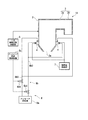
- FIG. 1 is a schematic diagram illustrating a configuration of a main part of a boiler according to a first embodiment of the present disclosure. It is a sectional view showing typically the schematic structure of the burner with which the boiler in a 1st embodiment of this indication is provided.
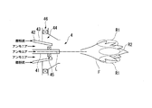
- FIG. 2 is a schematic diagram including a flame formed by a burner provided in the boiler according to the first embodiment of the present disclosure. It is sectional drawing which shows typically the schematic structure of the burner with which the boiler in 2nd Embodiment of this indication is provided. It is a mimetic diagram showing the important section composition of the boiler in a 3rd embodiment of this indication.
- FIG. 1 is a schematic diagram illustrating a main configuration of a boiler 1 according to the first embodiment.
- the boiler 1 includes a furnace 2, a flue 3, a burner 4 (combustion device), a two-stage combustion air supply unit 5, an ammonia supply unit 6, and a pulverized coal supply unit 7.
- a furnace 2 As shown in FIG. 1, the boiler 1 includes a furnace 2, a flue 3, a burner 4 (combustion device), a two-stage combustion air supply unit 5, an ammonia supply unit 6, and a pulverized coal supply unit 7.
- a furnace 2 includes a furnace 2, a flue 3, a burner 4 (combustion device), a two-stage combustion air supply unit 5, an ammonia supply unit 6, and a pulverized coal supply unit 7.
- a pulverized coal supply unit 7 Have.
- the furnace 2 is a furnace body that is constituted by vertical and cylindrical furnace walls and that burns fuel such as ammonia or pulverized coal to generate combustion heat.
- fuel such as ammonia or pulverized coal to generate combustion heat.
- high-temperature combustion gas is generated by burning the fuel.
- a discharge port 2a for discharging ash generated by fuel combustion to the outside.
- the flue 3 is connected to the upper part of the furnace 2 and guides the combustion gas generated in the furnace 2 to the outside as exhaust gas.
- the flue 3 includes a horizontal flue 3a extending horizontally from the upper part of the furnace 2 and a rear flue 3b extending downward from an end of the horizontal flue 3a.
- the boiler 1 includes a superheater installed at an upper part of the furnace 2 or the like.
- the superheater generates steam by exchanging heat between combustion heat generated in the furnace 2 and water.
- the boiler 1 includes a reheater, a economizer, an air preheater, and the like as necessary.
- the burner 4 is arranged on the lower wall of the furnace 2.
- a plurality of burners 4 are provided in the circumferential direction of the furnace 2. Although omitted in FIG. 1, a plurality of burners 4 are also provided in the height direction of the furnace 2.
- the burner 4 is arranged two-dimensionally and opposed to the lower part of the furnace 2, and injects and burns fuel.
- the burners 4 are all composite burners that can be injected into the furnace 2 using ammonia and pulverized coal as fuel.
- the furnace 2 is provided with an ignition device for igniting the fuel (ammonia and pulverized coal) injected from the burner 4.
- the boiler 1 has a combustion air supply unit that supplies combustion air to the burner 4. The fuel (ammonia and pulverized coal) injected from each burner 4 into the furnace 2 together with the combustion air is ignited and burned by the operation of the above-described ignition device.
- the burners 4 installed in the boiler 1 need not all be composite burners as described above.
- a configuration including a burner exclusively for coal or a burner exclusively for ammonia may be employed.
- ammonia is a compound of hydrogen (H) and nitrogen (N) as shown by the molecular formula, and does not include carbon (C) as a constituent atom.
- Ammonia (low-carbon fuel) is a hydrogen carrier substance having three hydrogen atoms, similar to methane (CH 3 ), although it is known as a flame-retardant substance.
- Pulverized coal is obtained by pulverizing coal, which is a fossil fuel, to a size of about several micrometers, and is generally used as fuel for boilers. That is, ammonia is a low-carbon fuel having a lower carbon concentration than pulverized coal (carbon fuel).
- FIG. 2 is a cross-sectional view schematically illustrating a schematic configuration of the burner 4.
- the burner 4 includes an inner cylinder nozzle 41, an outer cylinder nozzle 42, and a pulverized coal injection nozzle 43, and is generally formed in a substantially cylindrical shape centered on the axis L of the inner cylinder nozzle 41.
- the rear end of the inner cylinder nozzle 41 is connected to the ammonia supply unit 6 and injects ammonia into the furnace 2 from the front end of the inner cylinder nozzle 41.
- the inner cylinder nozzle 41 is disposed at the center of the burner 4 when viewed from the direction in which the burner 4 injects ammonia.
- the outer cylinder nozzle 42 is coaxially arranged with the inner cylinder nozzle 41 so as to surround the inner cylinder nozzle 41 from the outside in the radial direction when viewed from the ammonia injection direction of the burner 4 (the direction along the axis L).
- the rear end of the outer cylinder nozzle 42 is connected to the ammonia supply unit 6 and injects ammonia around the inner cylinder nozzle 41 from the front end of the outer cylinder nozzle 42.
- the pulverized coal injection nozzle 43 is provided concentrically with the inner cylinder nozzle 41 and the outer cylinder nozzle 42 so as to surround the outer cylinder nozzle 42 from the outside in the radial direction when viewed from the ammonia injection direction of the burner 4.
- the rear end of the pulverized coal injection nozzle 43 is connected to the pulverized coal supply unit 7 and injects air containing pulverized coal into the furnace 2 from the tip of the pulverized coal injection nozzle 43. That is, in the present embodiment, the pulverized coal injection nozzle 43 has a single-pipe structure for guiding the air containing the pulverized coal to and from the outer wall surface of the outer cylinder nozzle 42.
- the burner 4 includes a secondary air supply unit 44 disposed to surround the inner cylinder nozzle 41, the outer cylinder nozzle 42, and the pulverized coal injection nozzle 43, and an ammonia swirler disposed inside the outer cylinder nozzle 42. 45 (a swirler) and an air swirler 46 disposed inside the secondary air supply unit 44.
- the secondary air supply unit 44 supplies combustion air to the flame from the radial outside.
- the ammonia swirler 45 is arranged between the inner cylinder nozzle 41 and the outer cylinder nozzle 42.
- the ammonia swirler 45 is a cascade formed by a plurality of blades arranged in a circumferential direction about the axis L.
- the ammonia swirler 45 imparts a swirl component about the axis L to the flow of ammonia flowing between the inner cylinder nozzle 41 and the outer cylinder nozzle 42.
- the ammonia injected from the outer cylinder nozzle 42 is injected so as to turn around the axis L when viewed from the injection direction.
- the air swirler 46 is a cascade formed by a plurality of wings arranged in a circumferential direction about the axis L.
- the air swirler 46 imparts a swirl component about the axis L to the flow of air flowing inside the secondary air supply unit 44.
- the air supplied from the secondary air supply unit 44 to the furnace 2 is injected so as to turn around the axis L when viewed from the injection direction of ammonia.
- ammonia is injected from the inner cylinder nozzle 41 and the outer cylinder nozzle 42, pulverized coal is injected from the pulverized coal injection nozzle 43, and air for combustion is supplied, as shown in FIG.
- a flame F is formed in front of the burner 4.
- nitrogen (N) contained in ammonia and oxygen (O) contained in air are present in the outer edge region of the flame F (region radially outside the axis L of the inner cylinder nozzle 41).
- nitrogen oxide generation region R1 in which a large amount of nitrogen oxide is generated.
- a reduction region R2 in which the concentration of ammonia is high and the concentration of oxygen is low is formed by the ammonia injected from the inner cylinder nozzle 41.
- the two-stage combustion air supply unit 5 is connected to the furnace 2 above the burner 4, and supplies the inside of the furnace 2 with air for two-stage combustion.
- the two-stage combustion air supply unit 5 By supplying air for two-stage combustion by the two-stage combustion air supply unit 5, the unburned portion of the fuel burned by the burner 4 is burned by the two-stage combustion air.
- the heat collection performance of the boiler 1 can be improved, and the unburned fuel content in the exhaust gas can be reduced.
- the ammonia supply unit 6 includes an ammonia supply source 6a, a fuel ammonia supply unit 6b, and an ammonia supply control device 6c.
- the ammonia supply source 6a includes a tank for storing ammonia.
- the ammonia supply source 6a does not necessarily need to be a component of the ammonia supply unit 6. That is, the ammonia supply unit 6 may take in ammonia from the ammonia supply source 6a provided outside.
- the fuel ammonia supply unit 6b includes a fuel ammonia supply pipe 6b1 that connects the ammonia supply source 6a and the burner 4, and a flow rate control valve 6b2 that is provided at an intermediate portion of the fuel ammonia supply pipe 6b1.
- the fuel ammonia supply pipe 6b1 guides the ammonia supplied from the ammonia supply source 6a to the burner 4.
- the flow control valve 6b2 controls the flow rate of ammonia supplied from the ammonia supply source 6a to the fuel ammonia supply pipe 6b1.
- the ammonia supply control device 6c controls the flow control valve 6b2 to adjust the opening of the flow control valve 6b2.
- the ammonia supply control device 6c adjusts the flow rate of ammonia taken in from the ammonia supply source 6a by adjusting the opening of the flow control valve 6b2 based on an external command or the like.
- the pulverized coal supply unit 7 is connected to the burner 4, and pulverizes the coal into pulverized coal and supplies the pulverized coal to the burner 4.
- the pulverized coal supply unit 7 includes, for example, a mill that pulverizes coal to a particle size of about several micrometers to produce pulverized coal, and a coal feeder that supplies the pulverized coal generated by the mill to the burner 4.
- the pulverized coal supply unit 7 may be configured to directly supply pulverized coal to the burner 4 from a mill without a coal feeder.
- the inside of the furnace 2 is set to an air atmosphere lower than the theoretical air amount.
- ammonia is supplied from the ammonia supply unit 6 to the burner 4
- pulverized coal is supplied from the pulverized coal supply unit 7 to the burner 4
- a flame is formed by the burner 4 using the ammonia and the pulverized coal as fuel.
- the unburned fuel contained in the combustion gas generated by the burner 4 is burned.
- the combustion gas generated by burning the fuel moves from the lower part to the upper part of the furnace 2 and is guided to the outside through the flue 3.
- the ammonia injected from the inner cylinder nozzle 41 forms a reduction region R2 in which the ammonia concentration is high and the oxygen concentration is low in the center of the flame F when viewed from the fuel injection direction.
- the nitrogen oxide generated by the ammonia injected from the outer cylinder nozzle 42 to the periphery of the inner cylinder nozzle 41 mixed with oxygen and burned is relatively discharged from the relatively high pressure outer edge of the flame F. Is supplied to the reduction region R2 via a circulating flow that recirculates toward the center of the negative pressure.
- the nitrogen oxide generated at the outer edge of the flame F is reduced in the reduction region R2 formed by the ammonia injected from the inner cylinder nozzle 41, and becomes nitrogen gas (N 2 ). Therefore, according to the burner 4 of the present embodiment, it is possible to suppress an increase in nitrogen oxides.
- the burner 4 in the present embodiment includes an ammonia swirler 45 that is arranged inside the outer cylinder nozzle 42 and swirls the flow of ammonia injected around the inner cylinder nozzle 41.
- an ammonia swirler 45 that is arranged inside the outer cylinder nozzle 42 and swirls the flow of ammonia injected around the inner cylinder nozzle 41.
- the temperature of the injected ammonia is lower than the internal temperature of the furnace 2, so that the density of the ammonia is high and the injected ammonia depends on the weight. It has been confirmed that it is biased downward.
- the centrifugal force due to the swirl allows the ammonia to be evenly distributed in the radial direction about the axis L.
- the burner 4 in the present embodiment is provided with a pulverized coal injection nozzle 43 for injecting air containing pulverized coal around the outer cylinder nozzle 42 when viewed from the ammonia injection direction of the burner 4.
- the burner 4 in this embodiment can also generate combustion gas using pulverized coal as fuel in addition to ammonia.
- the pulverized coal injection nozzle 43 has a single-pipe structure for guiding air containing pulverized coal to and from the outer wall surface of the outer cylinder nozzle 42. Therefore, the burner 4 can be reduced in size as compared with the case where the pulverized coal injection nozzle 43 has a double pipe structure.
- FIG. 4 is a cross-sectional view schematically showing a schematic configuration of a burner 4A provided in the boiler of the present embodiment.
- the pulverized coal injection nozzle 43 of the burner 4A includes an inner pipe 43a and an outer pipe 43b.
- the inner tube 43a is arranged so as to surround the outer cylinder nozzle 42 from a radially outer side when viewed from the direction of ammonia injection of the burner 4A, and is coaxially arranged with the outer cylinder nozzle 42.
- the outer tube 43b is arranged so as to surround the inner tube 43a from the outside in the radial direction when viewed from the injection direction of ammonia from the burner 4A, and is coaxially arranged with the inner tube 43a.
- the outer pipe 43b guides air containing pulverized coal between the outer pipe 43b and the inner pipe 43a. That is, in the present embodiment, the pulverized coal injection nozzle 43 has a double pipe structure having the inner pipe 43a and the outer pipe 43b.
- the pulverized coal injection nozzle 43 can be unitized separately from the inner cylinder nozzle 41 and the outer cylinder nozzle 42 in advance, thereby facilitating assembly and maintenance work of the burner 4A. Can be. Further, since the shape and the injection direction of the pulverized coal injection nozzle 43 can be set without depending on the inner cylinder nozzle 41 and the outer cylinder nozzle 42, the pulverized coal injection angle and the like can be arbitrarily set.
- FIG. 5 is a schematic diagram showing a main configuration of the boiler 1A of the present embodiment.
- the fuel ammonia supply unit 6b is provided at a first pipe 6b3 connecting the ammonia supply source 6a and the inner cylinder nozzle 41 of the burner 4, and at an intermediate portion of the first pipe 6b3.
- a first flow control valve 6b4 first flow control unit.
- the fuel ammonia supply unit 6b includes a second pipe 6b5 that connects the ammonia supply source 6a and the outer cylinder nozzle 42 of the burner 4, and a second flow rate control valve 6b6 (the second 2 flow rate adjustment unit).
- the ammonia supply control device 6c controls the first flow control valve 6b4 to adjust the opening of the first flow control valve 6b4. Further, the ammonia supply control device 6c controls the second flow control valve 6b6 to adjust the opening of the second flow control valve 6b6.
- the flow rate of ammonia supplied to the inner cylinder nozzle 41 is adjusted by the first flow rate control valve 6b4 controlled by the ammonia supply control device 6c. Further, the flow rate of ammonia supplied to the outer cylinder nozzle 42 is adjusted by the second flow rate control valve 6b6 controlled by the ammonia supply control device 6c.
- the flow rate of ammonia injected from the inner cylinder nozzle 41 and the flow rate of ammonia injected from the outer cylinder nozzle 42 are individually determined. Can be adjusted. Therefore, for example, the ammonia injected from the inner cylinder nozzle 41 is changed without changing the flow rate of the ammonia injected from the outer cylinder nozzle 42 so that the ammonia concentration in the reduction region R2 is optimized to reduce the nitrogen oxide. Can be adjusted.
- the boiler for co-firing pulverized coal and ammonia as fuel has been described.
- the present disclosure is not limited to this.
- a configuration of co-firing natural gas and ammonia as fuel, a configuration of co-firing heavy oil or light oil and ammonia as fuel, or a configuration of burning only ammonia as fuel may be employed. That is, the present disclosure can be applied to boilers and burners that burn ammonia as fuel.
- the configuration including the ammonia swirler 45 is employed.
- the present disclosure is not limited to this, and a configuration without the ammonia swirler 45 may be adopted.
- the present disclosure can be applied to a combustion device and a boiler that burn ammonia as fuel.
Landscapes
- Engineering & Computer Science (AREA)
- Mechanical Engineering (AREA)
- General Engineering & Computer Science (AREA)
- Chemical & Material Sciences (AREA)
- Combustion & Propulsion (AREA)
- Combustion Of Fluid Fuel (AREA)
- Pre-Mixing And Non-Premixing Gas Burner (AREA)
Abstract
La présente invention concerne un appareil de combustion (4) qui injecte et brûle de l'ammoniac faisant office de combustible et est installé dans un four (2). L'appareil de combustion (4) comprend : un gicleur à barillet interne (41) qui injecte de l'ammoniac et qui est positionné au centre tel qu'observé depuis la direction d'injection du combustible ; et un gicleur à barillet externe (42) qui injecte de l'ammoniac dans la périphérie autour du gicleur à barillet interne et qui est positionné de façon à entourer le gicleur à barillet interne à partir de sa partie extérieure radiale tel qu'observé depuis la direction d'injection du combustible.
Priority Applications (4)
| Application Number | Priority Date | Filing Date | Title |
|---|---|---|---|
| AU2019339356A AU2019339356B2 (en) | 2018-09-11 | 2019-09-11 | Combustion device and boiler |
| DE112019004529.6T DE112019004529T5 (de) | 2018-09-11 | 2019-09-11 | Verbrennungsvorrichtung und kessel |
| MYPI2021000222A MY204186A (en) | 2018-09-11 | 2019-09-11 | Combustion device and boiler |
| US17/148,626 US12331926B2 (en) | 2018-09-11 | 2021-01-14 | Combustion device and boiler |
Applications Claiming Priority (2)
| Application Number | Priority Date | Filing Date | Title |
|---|---|---|---|
| JP2018169624A JP7485500B2 (ja) | 2018-09-11 | 2018-09-11 | 燃焼装置及びボイラ |
| JP2018-169624 | 2018-09-11 |
Related Child Applications (1)
| Application Number | Title | Priority Date | Filing Date |
|---|---|---|---|
| US17/148,626 Continuation US12331926B2 (en) | 2018-09-11 | 2021-01-14 | Combustion device and boiler |
Publications (1)
| Publication Number | Publication Date |
|---|---|
| WO2020054748A1 true WO2020054748A1 (fr) | 2020-03-19 |
Family
ID=69778117
Family Applications (1)
| Application Number | Title | Priority Date | Filing Date |
|---|---|---|---|
| PCT/JP2019/035616 Ceased WO2020054748A1 (fr) | 2018-09-11 | 2019-09-11 | Appareil de combustion et chaudière |
Country Status (6)
| Country | Link |
|---|---|
| US (1) | US12331926B2 (fr) |
| JP (2) | JP7485500B2 (fr) |
| AU (1) | AU2019339356B2 (fr) |
| DE (1) | DE112019004529T5 (fr) |
| MY (1) | MY204186A (fr) |
| WO (1) | WO2020054748A1 (fr) |
Cited By (3)
| Publication number | Priority date | Publication date | Assignee | Title |
|---|---|---|---|---|
| JP2022091595A (ja) * | 2020-12-09 | 2022-06-21 | 川崎重工業株式会社 | バーナ及びその制御方法、並びに、燃焼炉 |
| WO2023120397A1 (fr) * | 2021-12-24 | 2023-06-29 | 三菱重工業株式会社 | Système de chaudière à combustible à l'ammoniac |
| JPWO2024257430A1 (fr) * | 2023-06-14 | 2024-12-19 |
Families Citing this family (22)
| Publication number | Priority date | Publication date | Assignee | Title |
|---|---|---|---|---|
| JP7533754B2 (ja) * | 2021-02-19 | 2024-08-14 | 株式会社Ihi | 燃焼装置およびボイラ |
| KR102853264B1 (ko) * | 2021-02-19 | 2025-08-29 | 가부시키가이샤 아이에이치아이 | 연소 장치 및 보일러 |
| CN113217937A (zh) * | 2021-06-11 | 2021-08-06 | 西安热工研究院有限公司 | 一种利用氨燃烧降低燃煤机组二氧化碳排放的系统及方法 |
| CN113701183A (zh) * | 2021-07-15 | 2021-11-26 | 浙江大学 | 燃煤电站锅炉掺混nh3燃烧降低碳排放强度的方法和装置 |
| CN113864783B (zh) * | 2021-09-06 | 2022-08-05 | 清华大学 | 一种氨燃料快速热解分级喷射枪 |
| KR20240041970A (ko) | 2021-09-09 | 2024-04-01 | 미츠비시 파워 가부시키가이샤 | 보일러, 보일러 제어 방법, 및 보일러 개조 방법 |
| CN113898941B (zh) * | 2021-10-26 | 2025-06-24 | 西安热工研究院有限公司 | 一种同时燃用nh3和煤粉的直流燃烧器 |
| CN113944926B (zh) * | 2021-10-26 | 2025-07-04 | 西安热工研究院有限公司 | 一种同时燃用nh3和煤粉的旋流燃烧器 |
| JP7825416B2 (ja) | 2021-12-23 | 2026-03-06 | 三菱重工業株式会社 | アンモニア燃焼バーナ、ボイラ及びボイラの運転方法 |
| TWI850917B (zh) | 2021-12-24 | 2024-08-01 | 日商三菱重工業股份有限公司 | 噴燃器及具備此之鍋爐以及噴燃器的運作方法 |
| WO2023120701A1 (fr) * | 2021-12-24 | 2023-06-29 | 三菱重工業株式会社 | Brûleur et chaudière équipée de celui-ci, et procédé de fonctionnement de brûleur |
| KR20240011777A (ko) * | 2022-03-30 | 2024-01-26 | 미츠비시 파워 가부시키가이샤 | 버너, 및 보일러 |
| KR102939263B1 (ko) | 2022-04-28 | 2026-03-16 | 한국전력공사 | 암모니아와 석탄의 혼합 연소를 위한 버너 및 이에 적용되는 고온 저산소 가스의 공급 시스템 |
| CN114877334A (zh) * | 2022-04-28 | 2022-08-09 | 西安交通大学 | 一种用于工业煤粉锅炉的氨气和煤粉双燃料燃烧器 |
| CN115095863B (zh) * | 2022-06-01 | 2025-04-18 | 北京天地融创科技股份有限公司 | 一种多级掺氨逆喷旋流燃烧器及其使用方法 |
| US12565990B2 (en) * | 2022-07-12 | 2026-03-03 | Air Products And Chemicals, Inc. | Burner, system, and method for hydrogen-enhanced pulverized coal ignition |
| JP2024042824A (ja) * | 2022-09-16 | 2024-03-29 | 三菱重工業株式会社 | ボイラ制御装置、ボイラ制御方法、及び、ボイラ制御プログラム |
| CN119677991A (zh) * | 2022-12-09 | 2025-03-21 | 株式会社Ihi | 燃烧装置 |
| JP7727939B2 (ja) * | 2022-12-15 | 2025-08-22 | 三建産業株式会社 | アンモニア燃焼バーナ |
| JP7356118B1 (ja) | 2022-12-21 | 2023-10-04 | 株式会社ヨータイ | 炉構造体及びこれを用いた燃焼方法 |
| TWI897492B (zh) | 2023-06-21 | 2025-09-11 | 日商三菱重工業股份有限公司 | 燃燒器及具備其之鍋爐,以及燃燒器之運轉方法 |
| WO2025037472A1 (fr) * | 2023-08-15 | 2025-02-20 | 株式会社Ihi | Brûleur pour combustion de combustible mélangé à l'ammoniac et procédé de fabrication d'un système de combustion de combustible mélangé à l'ammoniac l'utilisant |
Citations (8)
| Publication number | Priority date | Publication date | Assignee | Title |
|---|---|---|---|---|
| JPH07310903A (ja) * | 1994-05-18 | 1995-11-28 | Hitachi Ltd | 微粉炭燃焼方法及び微粉炭バーナー |
| JP6296216B1 (ja) * | 2017-09-25 | 2018-03-20 | 中国電力株式会社 | 燃焼装置及び燃焼方法 |
| JP6332578B1 (ja) * | 2017-09-08 | 2018-05-30 | 中国電力株式会社 | 燃焼方法 |
| JP2018138863A (ja) * | 2017-02-24 | 2018-09-06 | 株式会社Ihi | 燃焼器及びボイラ |
| JP2018173177A (ja) * | 2017-03-31 | 2018-11-08 | 株式会社Ihi | 複合燃焼炉及び複合燃焼ボイラ |
| JP2018200144A (ja) * | 2017-05-29 | 2018-12-20 | 株式会社Ihi | 燃焼炉及びボイラ |
| JP2019086191A (ja) * | 2017-11-02 | 2019-06-06 | 株式会社Ihi | ボイラ |
| JP2019086189A (ja) * | 2017-11-02 | 2019-06-06 | 株式会社Ihi | 燃焼装置及びボイラ |
Family Cites Families (12)
| Publication number | Priority date | Publication date | Assignee | Title |
|---|---|---|---|---|
| US2335188A (en) * | 1940-08-03 | 1943-11-23 | Kennedy Van Saun Mfg & Eng | Fuel burner |
| JPS59115904A (ja) * | 1982-12-23 | 1984-07-04 | Hitachi Ltd | 微粉炭の燃焼法 |
| JP3434096B2 (ja) * | 1995-09-21 | 2003-08-04 | 三菱重工業株式会社 | ガス焚きバーナ |
| US6722295B2 (en) * | 2000-09-29 | 2004-04-20 | Bert Zauderer | Method for the combined reduction of nitrogen oxide and sulfur dioxide concentrations in the furnace region of boilers |
| JP2012035216A (ja) | 2010-08-09 | 2012-02-23 | Babcock Hitachi Kk | 排ガス浄化用触媒及びその製造方法、並びに排ガス中窒素酸化物の浄化方法 |
| JP5897363B2 (ja) * | 2012-03-21 | 2016-03-30 | 川崎重工業株式会社 | 微粉炭バイオマス混焼バーナ |
| US20130255551A1 (en) * | 2012-03-27 | 2013-10-03 | American Air Liquide, Inc. | Biomass Combustion |
| JP5916527B2 (ja) | 2012-06-19 | 2016-05-11 | 三菱日立パワーシステムズ株式会社 | 排ガスの脱硝方法 |
| JP2016032391A (ja) | 2014-07-30 | 2016-03-07 | 東洋エンジニアリング株式会社 | 複合エネルギーシステム |
| JP2016130619A (ja) | 2015-01-15 | 2016-07-21 | 国立大学法人東北大学 | 低燃焼性燃料燃焼装置 |
| JP6260606B2 (ja) | 2015-11-27 | 2018-01-17 | カシオ計算機株式会社 | 書画カメラシステム及び画像読み取り方法 |
| CN115164199B (zh) | 2022-07-08 | 2024-06-18 | 天津大学 | 氨煤混燃低氮燃烧器、氨煤混燃低氮燃烧炉及其使用方法 |
-
2018
- 2018-09-11 JP JP2018169624A patent/JP7485500B2/ja active Active
-
2019
- 2019-09-11 DE DE112019004529.6T patent/DE112019004529T5/de active Pending
- 2019-09-11 AU AU2019339356A patent/AU2019339356B2/en active Active
- 2019-09-11 WO PCT/JP2019/035616 patent/WO2020054748A1/fr not_active Ceased
- 2019-09-11 MY MYPI2021000222A patent/MY204186A/en unknown
-
2021
- 2021-01-14 US US17/148,626 patent/US12331926B2/en active Active
-
2023
- 2023-03-13 JP JP2023038643A patent/JP2023065706A/ja active Pending
Patent Citations (8)
| Publication number | Priority date | Publication date | Assignee | Title |
|---|---|---|---|---|
| JPH07310903A (ja) * | 1994-05-18 | 1995-11-28 | Hitachi Ltd | 微粉炭燃焼方法及び微粉炭バーナー |
| JP2018138863A (ja) * | 2017-02-24 | 2018-09-06 | 株式会社Ihi | 燃焼器及びボイラ |
| JP2018173177A (ja) * | 2017-03-31 | 2018-11-08 | 株式会社Ihi | 複合燃焼炉及び複合燃焼ボイラ |
| JP2018200144A (ja) * | 2017-05-29 | 2018-12-20 | 株式会社Ihi | 燃焼炉及びボイラ |
| JP6332578B1 (ja) * | 2017-09-08 | 2018-05-30 | 中国電力株式会社 | 燃焼方法 |
| JP6296216B1 (ja) * | 2017-09-25 | 2018-03-20 | 中国電力株式会社 | 燃焼装置及び燃焼方法 |
| JP2019086191A (ja) * | 2017-11-02 | 2019-06-06 | 株式会社Ihi | ボイラ |
| JP2019086189A (ja) * | 2017-11-02 | 2019-06-06 | 株式会社Ihi | 燃焼装置及びボイラ |
Cited By (7)
| Publication number | Priority date | Publication date | Assignee | Title |
|---|---|---|---|---|
| JP2022091595A (ja) * | 2020-12-09 | 2022-06-21 | 川崎重工業株式会社 | バーナ及びその制御方法、並びに、燃焼炉 |
| JP7498654B2 (ja) | 2020-12-09 | 2024-06-12 | 川崎重工業株式会社 | バーナ及びその制御方法、並びに、燃焼炉 |
| WO2023120397A1 (fr) * | 2021-12-24 | 2023-06-29 | 三菱重工業株式会社 | Système de chaudière à combustible à l'ammoniac |
| JP2023094928A (ja) * | 2021-12-24 | 2023-07-06 | 三菱重工業株式会社 | アンモニア燃料ボイラシステム |
| JPWO2024257430A1 (fr) * | 2023-06-14 | 2024-12-19 | ||
| WO2024257430A1 (fr) * | 2023-06-14 | 2024-12-19 | 株式会社Ihi | Chambre de combustion |
| JP7835350B2 (ja) | 2023-06-14 | 2026-03-25 | 株式会社Ihi | 燃焼器 |
Also Published As
| Publication number | Publication date |
|---|---|
| MY204186A (en) | 2024-08-14 |
| US20210140634A1 (en) | 2021-05-13 |
| JP7485500B2 (ja) | 2024-05-16 |
| AU2019339356A1 (en) | 2021-02-11 |
| JP2023065706A (ja) | 2023-05-12 |
| AU2019339356B2 (en) | 2022-01-27 |
| DE112019004529T5 (de) | 2021-05-27 |
| US12331926B2 (en) | 2025-06-17 |
| JP2020041748A (ja) | 2020-03-19 |
Similar Documents
| Publication | Publication Date | Title |
|---|---|---|
| JP7485500B2 (ja) | 燃焼装置及びボイラ | |
| JP7027817B2 (ja) | 燃焼装置及びボイラ | |
| JP6950464B2 (ja) | ボイラ | |
| KR101436777B1 (ko) | 연소 버너 및 이 연소 버너를 구비하는 보일러 | |
| BG64878B1 (bg) | Горелка за твърдо гориво и метод за регулиране нагоренето, осъществявано от горелката за твърдо гориво | |
| CN106287667A (zh) | 一种设有SOFA的高温烟气回流预燃式低NOx燃烧器 | |
| KR102686756B1 (ko) | 연소 장치 및 보일러 | |
| US11959638B2 (en) | Boiler | |
| EP3469258A1 (fr) | Procédé de combustion de combustible et chaudière | |
| WO2022176347A1 (fr) | Dispositif de combustion et chaudière | |
| JP7816486B2 (ja) | 燃焼装置 | |
| JP7468772B2 (ja) | 燃焼装置およびボイラ | |
| JP7834474B2 (ja) | バーナ及び燃焼炉 | |
| CN102226520B (zh) | 一种直接点燃垂直浓淡煤粉气流的燃烧装置及燃烧方法 | |
| JP7662111B1 (ja) | アンモニア混焼バーナ、並びにこれを用いたアンモニア混焼システムの製造方法 | |
| JP6926961B2 (ja) | ボイラ | |
| JP2024168313A (ja) | バーナ及び燃焼炉 | |
| JP2009109067A (ja) | 混焼バーナおよびボイラ | |
| JP2023160352A (ja) | 粉状燃料バーナ | |
| JPH0241443Y2 (fr) | ||
| CN121761301A (zh) | 一种前后墙对冲锅炉的掺氨燃烧系统 | |
| JPS5817365B2 (ja) | 2流体噴霧バ−ナ |
Legal Events
| Date | Code | Title | Description |
|---|---|---|---|
| 121 | Ep: the epo has been informed by wipo that ep was designated in this application |
Ref document number: 19859444 Country of ref document: EP Kind code of ref document: A1 |
|
| ENP | Entry into the national phase |
Ref document number: 2019339356 Country of ref document: AU Date of ref document: 20190911 Kind code of ref document: A |
|
| 122 | Ep: pct application non-entry in european phase |
Ref document number: 19859444 Country of ref document: EP Kind code of ref document: A1 |