WO2020054837A1 - Électrovanne linéaire - Google Patents
Électrovanne linéaire Download PDFInfo
- Publication number
- WO2020054837A1 WO2020054837A1 PCT/JP2019/036063 JP2019036063W WO2020054837A1 WO 2020054837 A1 WO2020054837 A1 WO 2020054837A1 JP 2019036063 W JP2019036063 W JP 2019036063W WO 2020054837 A1 WO2020054837 A1 WO 2020054837A1
- Authority
- WO
- WIPO (PCT)
- Prior art keywords
- land portion
- port
- spool
- output
- output port
- Prior art date
- Legal status (The legal status is an assumption and is not a legal conclusion. Google has not performed a legal analysis and makes no representation as to the accuracy of the status listed.)
- Ceased
Links
Images


Classifications
-
- F—MECHANICAL ENGINEERING; LIGHTING; HEATING; WEAPONS; BLASTING
- F16—ENGINEERING ELEMENTS AND UNITS; GENERAL MEASURES FOR PRODUCING AND MAINTAINING EFFECTIVE FUNCTIONING OF MACHINES OR INSTALLATIONS; THERMAL INSULATION IN GENERAL
- F16K—VALVES; TAPS; COCKS; ACTUATING-FLOATS; DEVICES FOR VENTING OR AERATING
- F16K11/00—Multiple-way valves, e.g. mixing valves; Pipe fittings incorporating such valves
- F16K11/02—Multiple-way valves, e.g. mixing valves; Pipe fittings incorporating such valves with all movable sealing faces moving as one unit
- F16K11/06—Multiple-way valves, e.g. mixing valves; Pipe fittings incorporating such valves with all movable sealing faces moving as one unit comprising only sliding valves, i.e. sliding closure elements
- F16K11/065—Multiple-way valves, e.g. mixing valves; Pipe fittings incorporating such valves with all movable sealing faces moving as one unit comprising only sliding valves, i.e. sliding closure elements with linearly sliding closure members
- F16K11/07—Multiple-way valves, e.g. mixing valves; Pipe fittings incorporating such valves with all movable sealing faces moving as one unit comprising only sliding valves, i.e. sliding closure elements with linearly sliding closure members with cylindrical slides
-
- F—MECHANICAL ENGINEERING; LIGHTING; HEATING; WEAPONS; BLASTING
- F16—ENGINEERING ELEMENTS AND UNITS; GENERAL MEASURES FOR PRODUCING AND MAINTAINING EFFECTIVE FUNCTIONING OF MACHINES OR INSTALLATIONS; THERMAL INSULATION IN GENERAL
- F16K—VALVES; TAPS; COCKS; ACTUATING-FLOATS; DEVICES FOR VENTING OR AERATING
- F16K3/00—Gate valves or sliding valves, i.e. cut-off apparatus with closing members having a sliding movement along the seat for opening and closing
- F16K3/22—Gate valves or sliding valves, i.e. cut-off apparatus with closing members having a sliding movement along the seat for opening and closing with sealing faces shaped as surfaces of solids of revolution
- F16K3/24—Gate valves or sliding valves, i.e. cut-off apparatus with closing members having a sliding movement along the seat for opening and closing with sealing faces shaped as surfaces of solids of revolution with cylindrical valve members
-
- F—MECHANICAL ENGINEERING; LIGHTING; HEATING; WEAPONS; BLASTING
- F16—ENGINEERING ELEMENTS AND UNITS; GENERAL MEASURES FOR PRODUCING AND MAINTAINING EFFECTIVE FUNCTIONING OF MACHINES OR INSTALLATIONS; THERMAL INSULATION IN GENERAL
- F16K—VALVES; TAPS; COCKS; ACTUATING-FLOATS; DEVICES FOR VENTING OR AERATING
- F16K31/00—Actuating devices; Operating means; Releasing devices
- F16K31/02—Actuating devices; Operating means; Releasing devices electric; magnetic
- F16K31/06—Actuating devices; Operating means; Releasing devices electric; magnetic using a magnet, e.g. diaphragm valves, cutting off by means of a liquid
Definitions
- This technology relates to a linear solenoid valve that performs feedback control using output hydraulic pressure output from an output port.
- a hydraulic control device for hydraulically controlling engagement of a clutch or a brake is provided with a linear solenoid valve that regulates and outputs an engagement pressure.
- a linear solenoid valve has an input port, an output port, a discharge port, and a feedback port. A part of the output oil pressure is supplied to the feedback oil chamber as a feedback pressure, and the feedback pressure is applied to the difference in valve area.
- Has a feedback structure for urging the valve in the direction of the electromagnetic portion of the solenoid see Patent Document 1.
- the linear solenoid valve provided with a feedback port as in Patent Literature 1 has a problem that the overall length in the axial direction is increased by the amount of the feedback port.
- the feedback port needs to be provided with a difference in the diameter of the land portion of the spool. Therefore, the feedback port is generally arranged on the end side of the valve portion with respect to the other ports.
- the driving load cannot be reduced, which hinders improvement in fuel efficiency of a vehicle equipped with the linear solenoid valve.
- This linear solenoid valve is A solenoid unit that drives the plunger according to the supplied current;
- a sleeve having an input port, an output port, and a discharge port, each of which is constituted by a through hole and arranged in order in the axial direction,
- a spool slidably inserted into the sleeve,
- the spool has a first land portion and a second land portion, and the axial position is controlled by pressing the plunger, so that the first land portion allows the input port and the output port to be connected to each other.
- the first land portion when the spool is at the first position, blocks input hydraulic pressure input to the input port by a side surface on the input port side in the axial direction, and the spool is moved to the second position by the second port.
- the output hydraulic pressure can be adjusted by allowing the input hydraulic pressure to flow out of the output port, The first land portion and the second land portion so that output hydraulic pressure output from the output port also acts as feedback pressure on the spool in a direction from the output port to the input port in the axial direction of the spool.
- An outer diameter difference was provided between the land portion.
- FIG. 2 is a cross-sectional view showing the linear solenoid valve according to the first embodiment.
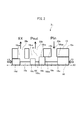
- FIG. 2 is a schematic sectional view showing a valve portion of the linear solenoid valve according to the first embodiment.
- FIG. 4 is a schematic cross-sectional view showing a valve portion of a linear solenoid valve according to a second embodiment.
- FIG. 9 is a schematic cross-sectional view illustrating a valve portion of a linear solenoid valve according to a third embodiment.
- FIG. 13 is a schematic cross-sectional view illustrating a valve portion of a linear solenoid valve according to a fourth embodiment.
- FIG. 14 is a schematic sectional view showing a valve section of a linear solenoid valve according to a fifth embodiment.
- FIG. 4 is a schematic cross-sectional view showing a valve section of a linear solenoid valve according to a first reference example.
- FIG. 4 is a schematic cross-sectional view showing a valve portion of a linear solenoid valve according to a second reference example.
- FIG. 1 is a sectional view showing a linear solenoid valve according to the first embodiment
- FIG. 2 is a schematic sectional view showing a valve portion of the linear solenoid valve according to the first embodiment.
- the linear solenoid valve 1 is a so-called normally closed type linear solenoid valve, which is used for a hydraulic control device mounted on a vehicle drive device such as an automatic transmission or a hybrid drive device.
- a linear solenoid valve that regulates the engagement pressure supplied to the hydraulic servo of the clutch or brake of the transmission mechanism, a linear solenoid valve that regulates the engagement pressure supplied to the lock-up clutch, and regulates the line pressure Therefore, it is used for a linear solenoid valve or the like that regulates a control pressure according to a throttle opening.
- the linear solenoid valve 1 has a solenoid part 2 and a valve part 3, and the valve part 3 is used by being mounted on a valve body 5 of a hydraulic control device (not shown).
- the solenoid portion 2 is slidably fitted to a coil 6 wound on a bobbin, a first core 7 and a second core 9 mounted so as to cover the coil 6, and a hollow portion of the second core 9.
- a plunger 10 inserted therein, a rod member 11 slidably disposed in a hollow member 8 fitted in the first core 7, and a yoke 12 covering the above members and integrally connected to the valve portion 3.
- the first and second cores 7 and 9, the plunger 10 and the yoke 12 are made of a ferromagnetic material, and the portion between the rod member 11 and the first and second cores 7 and 9 is made of a non-magnetic material. Is supplied from the terminal 13 to the coil 6, a magnetic flux circuit is formed which flows in the order of the first core 7 through the yoke 12, the second core 9, and the plunger 10, and the plunger 10 based on the magnetic flux circuit is formed. The pressing force is transmitted to the spool 16 of the valve section 3 via the rod member 11.
- the valve section 3 has a sleeve 15 and a spool 16.
- the sleeve 15 has a cylindrical shape over substantially the entire length, and an outer peripheral surface 15 a of the sleeve 15 is inserted into the installation hole 5 a of the valve body 5. As a result, it is mounted on the valve body 5.
- the spool 16 is slidably fitted on the inner peripheral surface 15b of the sleeve 15.
- An enlarged diameter portion 15g is formed on one end of the sleeve 15, and the tip of the yoke 12 is caulked to the enlarged diameter portion 15g, so that the solenoid portion 2 and the valve portion 3 are integrally assembled. .
- a cap 17 is screwed and fixed to the other end, which is an end of the sleeve 15, to prevent the spool 16 from coming off inside the sleeve 15, and to end the cap 17 and the end of the spool 16 (details will be described later).
- the spring 19 as an urging member is contracted between the land portion 16d).
- the spring 19 is disposed on the side opposite to the solenoid portion 2 with respect to the spool 16 in the axial direction so as to urge the spool 16 in opposition to the pressing of the plunger 10.
- the opposite end of the spool 16 is in contact with the rod member 11 of the solenoid unit 2, and the spool 16 applies the pressing force of the plunger 10 and the urging force of the spring 19 (and the feedback pressure described later). Is controlled to a balanced position.
- the sleeve 15 has an input port 20a, an output port 20b, and a drain port 20c which are formed by through holes penetrating from the outer peripheral surface 15a to the inner peripheral surface 15b. It communicates with each formed oil passage.
- an input port 20a, an output port 20b, and a drain port 20c (discharge port) are formed in the sleeve 15 in the axial direction AX that is the moving direction of the spool 16 from the solenoid portion 2 side.
- An input oil pressure Pin such as a line pressure is input to the input port 20a, and an output oil pressure Pout serving as an engagement pressure supplied to a hydraulic servo or the like is output from the output port 20b.
- the hydraulic pressure is discharged (EX) from the drain port 20c so as to be released to the atmosphere via the oil passage of the valve body 5.
- the spool 16 has a land portion 16a, a land portion 16b (first land portion), a land portion 16c (second land portion), and a land portion 16d in this order from the side of the solenoid portion 2 in the axial direction.
- Each of the land portions has a smaller diameter than each land portion, and has a shaft portion 16e, a shaft portion 16f, and a shaft portion 16g connecting the land portions.
- Each land portion is formed so as to slide on the inner peripheral surface 15b of the sleeve 15, and more specifically, a sliding surface 16aa which is an outer peripheral surface of the land portion 16a, and a sliding surface which is an outer peripheral surface of the land portion 16b.
- the sliding surface 16ca, which is the outer peripheral surface of the land portion 16c, and the sliding surface 16da, which is the outer peripheral surface of the land portion 16d, are slidable with the inner peripheral surface 15b of the sleeve 15, respectively.
- the lands 16c and 16d are formed to have an outer diameter d1
- the lands 16a and 16b are formed to have an outer diameter d2 larger than the outer diameter d1.
- the lands 16a and 16b have a larger diameter than the lands 16c and 16d.
- a notch N1 is formed at an end of the land 16b on the side of the input port 20a in the axial direction, and a notch N2 is formed at an end of the land 16c on the side of the drain port 20c in the axial direction. Have been. The function of the notches N1 and N2 will be described later.
- An input oil pressure Pin such as a line pressure is input to the input port 20a, and when the solenoid unit 2 shown in FIG. 2 is de-energized, the spool 16 is moved by the urging force of the spring 19 to move the solenoid unit 2 in the axial direction.
- the output port 20b and the drain port 20c communicate with each other, that is, the output hydraulic pressure Pout is discharged to zero pressure.
- the input oil pressure Pin is blocked by the side surface 16bb of the land portion 16b on the side of the input port 20a.
- the land portion 16b opens to the output port 20b, and the inflow from the input port 20a to the output port 20b increases, and the land portion 16c Closes the gap between the output port 20b and the drain port 20c, the amount of discharge from the output port 20b to the drain port 20c decreases, and finally the position where the spool 16 has moved most toward the spring 19 in the axial direction ( At the second position, the input oil pressure Pin of the input port 20a flows out as it is as the output oil pressure Pout of the output port 20b.
- the land portion 16d is disposed on the opposite side of the land portion 16c in the axial direction from the land portion 16b, and is configured to block leakage of hydraulic pressure discharged from the drain port.
- the input hydraulic pressure Pin is accumulated around the shaft portion 16e of the spool 16 by the side surface 16bb of the land portion 16b on the side of the input port 20a and is blocked, and the input hydraulic pressure Pin is gradually moved to the output port 20b as the land portion 16b moves.
- the magnitude of the output oil pressure Pout by letting the input oil pressure Pin flow out, the outflow amount (throttle amount) flowing from the inside of the sleeve 15 toward the output port 20b is adjusted. It is called "spill restriction".
- the output oil pressure Pout When the output oil pressure Pout is increased by moving the spool 16 as described above, as described above, the output of the output port 20b is output to the feedback oil chamber 31 caused by the pressure receiving area difference between the land 16b and the land 16c.
- the hydraulic pressure Pout acts on the spool 16 to act as a feedback pressure corresponding to the output oil pressure Pout toward the solenoid portion 2 in the axial direction, that is, the spool 16 restricts the outflow of the input oil pressure Pin by the output oil pressure Pout. Feedback control is performed in the direction.
- the valve portion 3 1 of the linear solenoid valve 1 according to the first embodiment will be feedback oil chamber 31 is disposed inside the output port 20b in the axial direction.
- valve portion 103 1 of the linear solenoid valve of the first reference example in which the outflow aperture shown in FIG.
- the valve portion 103 1 of the first reference example the input port 120a, the output port 120b, a sleeve 115 having a drain port 120c, and a feedback port 120d, sliding on the inner peripheral surface 115b of the sleeve 115
- the spool 116 is provided with a land portion 116a, a land portion 116b, a land portion 116c, and a land portion 116d in order in the axial direction.
- a shaft portion 116e, a shaft portion 116f, and a shaft portion 116g for connecting the portions are provided.
- a closing plate 115c arranged in a cylindrical shape straddling in the axial direction and an orifice 115d which is a through hole formed in the closing plate 115c are arranged to provide feedback.
- An oil chamber 131 is formed.
- the land portion 16d is the land portion 16b, which is disposed on the outermost end of the plurality of land portions including a land portion 16c, and the land portion 16a, a feedback Since there is no port, that is, there is no land portion constituting the feedback port, the sleeve 15 and the spool 16 can be shortened. Further, since the portion where the feedback pressure acts is the same as the output hydraulic pressure Pout, the sealing performance of the feedback pressure is achieved. a portion of securing is not necessary, even if the minute, the sleeve 15 can be shortened and the spool 16, i.e. it is possible to shorten the valve portion 3 1.
- valve portion 103 1 of the first reference example even if the sleeve 115 and spool 116 to secure the sealing property as the long, the sealing property is limited, axial from the feedback port 120d (feedback oil chamber 131)
- the output hydraulic pressure Pout will leak to both sides in the direction.
- the output hydraulic pressure Pout leaks between the outer peripheral surface 115a of the sleeve 115 and the valve body.
- valve portion 3 1 of the first embodiment (min output port 20b and the feedback oil chamber 31 is shared) minute feedback port is not, the output hydraulic pressure Pout are places is reduced leak, leak amount is small That is, the consumption flow rate of the linear solenoid valve 1 can be reduced.
- the linear solenoid valve 1 according to the first embodiment has a smaller number of parts and can be reduced in price as compared with a case using such two spools.
- valve portion 3 1 As described above, the valve portion 3 1 according to the first embodiment, yet as it is possible to perform a feedback control, it is possible to shorten the axial direction and also possible to achieve a reduction in consumption flow rate Can be.
- the valve unit 3 1 since one in which pressure regulating the output hydraulic pressure Pout by outlet throttle as described above, the input hydraulic pressure Pin is an output port that was blocked by the side surface 16bb of the land portion 16b When the oil flows out to the outlet port 20b, the oil flows from the spool 16 toward the output port 20b in the outer diameter direction. Therefore, the jet flow based on the input oil pressure Pin does not directly hit the side surface 16bc on the side of the output port 20b (the drain port 20c) in the axial direction of the land portion 16b on the side with the larger outer diameter, and acts as a disturbance to the feedback pressure. Therefore, the accuracy of the feedback control can be improved.
- FIG. 3 is a schematic cross-sectional view showing a valve portion of a linear solenoid valve according to the second embodiment.
- Valve part 3 2 of the linear solenoid valve 1 according to the second embodiment is different from the first embodiment, as shown in FIG. 3, the seal ring S1 outer circumferential surface into three sleeves 15, S2, S3 It is provided with.
- the valve portion 3 2 which is inserted into the installation hole 5a of the valve body 5 (see FIG. 1), hydraulic leaks slightly between the outer peripheral surface 15a of the mounting hole 5a and the sleeve 15 of the valve body 5.
- the input hydraulic pressure Pin is input to the input port 20a, and the output hydraulic pressure Pout is output from the output port 20b. Therefore, by sealing both sides of these ports in the axial direction, the flow consumption of the linear solenoid valve 1 is reduced. It is possible to do.
- valve portion 3 2 in the outer periphery of the sleeve 15, the seal ring S1, located on the opposite side of the output port 20b to the input port 20a in the axial direction (first seal ring) in the axial direction
- a seal ring S2 second seal ring
- a seal ring S3 third seal ring
- valve portion 103 1 of the linear solenoid valve of the first reference example since the output hydraulic pressure Pout is supplied to the feedback port 120d, have a seal ring S4, S5 arranged on both sides in the axial direction of the feedback port 120d for example, the leakage caused by the output oil pressure Pout cannot be reduced, and the consumption flow rate cannot be reduced. Therefore, when disposing the seal rings, it is necessary to dispose five seal rings S1, S2, S3, S4, and S5.
- valve portion 3 2 since the feedback port is not may be sealed for the input port 20a and output port 20b, sharing the seal ring S2, 3 pieces of the seal ring S1, Only by arranging S2 and S3, the consumption flow rate can be reduced. Therefore, while the consumption flow rate can be reduced, the number of seal rings can be reduced and the cost can be reduced as compared with the one having the feedback port.
- the linear solenoid valve 1 according to the second embodiment is the same as the first embodiment in other configurations, operations, and effects, and thus the description thereof is omitted.
- FIG. 4 is a schematic sectional view showing a valve portion of a linear solenoid valve according to the third embodiment.
- Valve unit 3 3 of the linear solenoid valve 1 according to the third embodiment is different from the second embodiment, as shown in FIG. 4, as the feedback oil chamber forming portion 15F that forms a feedback oil chamber 31, surrounded
- the sleeve 15 has a portion 15c and an orifice 15d.
- the surrounding portion 15c is disposed astride the land portion 16b and the land portion 16c, and the outer peripheral side of the shaft portion 16f is slid on the sliding surface 16ba of the land portion 16b and the sliding surface 16ca of the land portion 16c. It is annularly formed and arranged so as to surround it, and forms a feedback oil chamber 31 inside.
- An orifice 15d which is a through hole, is formed in the surrounding portion 15c, and is configured to communicate the output port 20b and the feedback oil chamber 31.
- the output oil pressure Pout of the output port 20b is input as the feedback pressure FB. It is configured as follows.
- the surrounding portion 15c is connected by being formed integrally with the sleeve 15, and is fixed so as not to be movable in the axial direction.
- the feedback oil chamber forming portion 15F configured as described above buffers the output oil pressure Pout input to the feedback oil chamber 31 by the orifice 15d even if the output oil pressure Pout pulsates, and stabilizes the fluctuation of the feedback pressure. be able to. Further, even if the land 16b is opened to the output port 20b and the input oil pressure Pin flows out as a jet, the jet does not directly hit the feedback oil chamber 31 by the surrounding portion 15c. It can also be prevented.
- valve portion of the third embodiment 3 3 is suitable for easily pulsation output hydraulic pressure as the performance of the linear solenoid valve 1, suitable for use as outputting large input hydraulic Pin temper pressure in the output hydraulic pressure Pout It is.
- the linear solenoid valve 1 according to the third embodiment is the same as the first and second embodiments in other configurations, operations, and effects, and thus the description thereof is omitted.
- FIG. 5 is a schematic cross-sectional view showing a valve portion of a linear solenoid valve according to a fourth embodiment.
- This valve portion 3 4 of the linear solenoid valve 1 according to the fourth embodiment, as compared with the first to third embodiments, as shown in FIG. 5, when the solenoid portion 2 is de-energized, the spool 16 Is located at a position (first position) on the side of the solenoid portion 2 in the axial direction by the urging force of the spring 19, and the input hydraulic pressure Pin input to the input port 20a is applied to the sliding surface 16ba of the land portion 16b (first land portion). When the spool 16 moves, the land portion 16b opens the input port 20a and flows into the output port 20b as the output hydraulic pressure Pout.
- the input hydraulic pressure Pin is blocked by the sliding surface 16ba of the input port 20a of the land 16b to the input port 20a, and the input hydraulic pressure Pin gradually flows into the output port 20b as the land 16b moves.
- Adjusting the magnitude of the output hydraulic pressure Pout by performing the adjustment is referred to as “inflow restriction” because the flow amount (restriction amount) flowing from the input port 20a toward the inside of the sleeve 15 is adjusted.
- the land portion 16b constitutes has set the pressure receiving area difference consists in diameter than the land portion 16c, these land portion 16b, a feedback oil chamber 31 between 16c.
- a feedback pressure corresponding to the output oil pressure Pout output from the output port 20b acts on the spool 16, that is, the spool 16 is feedback-controlled by the output oil pressure Pout so as to restrict the outflow of the input oil pressure Pin.
- the valve portion 3 4 of the linear solenoid valve 1 according to the fourth embodiment will be feedback oil chamber 31 is disposed inside the output port 20b in the axial direction. Therefore, in the valve unit 3 4 according to the fourth embodiment, since the feedback port is not, despite those which can feedback control, it is possible to shorten the axial direction can be achieved also reduce the consumption flow .
- the valve portion 103 2 of the linear solenoid valve of the second reference example for the outflow aperture shown in FIG.
- the valve portion 103 2 of the second reference example the input port 120a, the output port 120b, a sleeve 115 having a drain port 120c, and a feedback port 120d, sliding on the inner peripheral surface 115b of the sleeve 115
- the spool 116 has a land portion 116a, a land portion 116b, and a land portion 116c in the axial direction, and connects the land portions.
- a shaft portion 116e and a shaft portion 116f are provided.
- a closing plate 115c arranged in a cylindrical shape straddling in the axial direction and an orifice 115d which is a through hole formed in the closing plate 115c are arranged to provide feedback.
- An oil chamber 131 is formed.
- the feedback pressure substantially equal to the output hydraulic pressure Pout acts on the feedback oil chamber 131, the feedback pressure is prevented from leaking between the land portion 116a and the inner peripheral surface 115b of the sleeve 115 and between the land portion 116b and the sleeve 116b. It is necessary to secure the sealing property by long overlap in the axial direction between the inner peripheral surface 115b and the inner peripheral surface 115b, and the axial length of the land portion 116a and the land portion 116b and the sleeve 115 becomes longer.
- the valve unit 3 4 according to the fourth embodiment, the land portion 16c are disposed on the outermost end of the plurality of land portions including a land portion 16b, partial feedback port is not, that is, the feedback port
- the sleeve 15 and the spool 16 can be shortened by the absence of the lands, and the portion where the feedback pressure acts is the same as the output hydraulic pressure Pout. even minute, the sleeve 15 can be shortened and the spool 16, i.e. it is possible to shorten the valve unit 3 4.
- valve portion 103 2 of the second reference example even if the sleeve 115 and spool 116 to secure the sealing property as the long, the sealing property is limited, axial from the feedback port 120d (feedback oil chamber 131)
- the output hydraulic pressure Pout will leak to both sides in the direction.
- the valve portion 3 4 of the fourth embodiment as shown in FIG.
- the minute feedback port is not (min output port 20b and the feedback oil chamber 31 is shared), three seal rings S1, Only by arranging S2 and S3, it is possible to seal between the outer peripheral surface 15a of the sleeve 15 and the installation hole 5a of the valve body 5, so that the consumption flow rate can be reduced. Therefore, while the consumption flow rate can be reduced, the number of seal rings can be reduced and the cost can be reduced as compared with the one having the feedback port.
- the input port 20a is open to a part of the entire circumference. Therefore, the leakage between the inner peripheral surface 15b of the sleeve 15 and the sliding surface 16ba is only a part in the circumferential direction, and the consumption flow rate can be reduced as compared with the structure of the outflow restrictor.
- valve portion 3 4 of the fourth embodiment as compared with the first to third embodiments, the axial position of the input port 20a and the drain port 20c is reversed, i.e. drain to the side of the solenoid portion 2
- the port 20c can be arranged, and the input port 20a can be arranged on the spring 19 side. Therefore, it is possible to cope with a case where the oil passage (oil passage for supplying line pressure or the like) communicating with the input port 20a cannot be arranged on the side of the solenoid unit 2 due to the arrangement of the oil passage in the valve body 5.
- the linear solenoid valve 1 according to the fourth embodiment is the same as the first to third embodiments in other configurations, operations, and effects, and thus the description thereof is omitted.
- FIG. 6 is a schematic sectional view showing a valve portion of a linear solenoid valve according to a fifth embodiment.
- Valve section 35 of the linear solenoid valve 1 according to the fifth embodiment is different from the fourth embodiment, as shown in FIG. 6, as a feedback oil chamber forming portion 15F that forms a feedback oil chamber 31, surrounded The sleeve 15 has a portion 15c and an orifice 15d.
- the spool 16 is located between the land portion (fourth land portion) 16b and the land portion (fifth land portion) 16c in the axial direction and on the inner peripheral side of the output port 20b.
- a land portion 16h (sixth land portion) is formed at a position, and is located at a position on the inner peripheral side of the output port 20b, between the land portion 16h and the land portion 16c in the axial direction.
- Land portions 16i (seventh land portions) are formed so as to be arranged.
- the surrounding portion 15c is disposed astride the land portion 16h and the land portion 16i.
- the outer peripheral side of the shaft portion 16f is slid on the sliding surface 16ha of the land portion 16h and the sliding surface 16ia of the land portion 16i. It is annularly formed and arranged so as to surround it, and forms a feedback oil chamber 31 inside.
- An orifice 15d which is a through hole, is formed in the surrounding portion 15c, and is configured to communicate the output port 20b and the feedback oil chamber 31.
- the output oil pressure Pout of the output port 20b is input as the feedback pressure FB. It is configured as follows.
- the surrounding portion 15c is connected by being formed integrally with the sleeve 15, and is fixed so as not to be movable in the axial direction.
- the feedback oil chamber forming portion 15F configured as described above buffers the output oil pressure Pout input to the feedback oil chamber 31 by the orifice 15d even if the output oil pressure Pout pulsates, and stabilizes the fluctuation of the feedback pressure. be able to. Further, in the valve unit 35 which is configured as a structural diaphragm inlet, the land portion 16b opens the output port 20b, even if the input hydraulic pressure Pin flows into toward the interior of the sleeve 15 as a jet, the jet by the surrounding portion 15c Does not directly hit the feedback oil chamber 31, it is also possible to prevent disturbance in feedback control.
- the linear solenoid valve 1 according to the fifth embodiment is the same as the first to fourth embodiments in other configurations, operations, and effects, and thus the description thereof is omitted.
- This linear solenoid valve (1) (for example, see FIGS. 1 to 4) A solenoid unit (2) for driving a plunger (10) according to the supplied current; A sleeve (15) having an input port (20a), an output port (20b), and a discharge port (20c), each of which is constituted by a through hole and arranged in the axial direction in order; A spool (16) slidably inserted into the sleeve, The spool (16) has a first land portion (16b) and a second land portion (16c), and the position in the axial direction is controlled by pressing the plunger (10), so that the second land portion (16b) is controlled.
- the input port (20a) and the output port (20b) are shut off by one land portion (16b), and the output port (20b) and the discharge port (20c) are communicated by the second land portion (16c). From the first position, the input port (20a) and the output port (20b) are communicated by the first land portion (16b), and the output port (20b) is connected to the output port (20b) by the second land portion (16c). Movable to a second position to shut off the discharge port (20c), When the spool (16) is at the first position, the first land portion (16b) transmits the input oil pressure (Pin) input to the input port (20a) to the input port (20a) in the axial direction.
- Pin input oil pressure
- the linear solenoid valve 1 can be shortened in the axial direction while having the feedback structure, and the flow rate consumed can be reduced.
- the jet flow based on the input hydraulic pressure Pin does not directly hit the side surface 16bc of the land portion 16b, and the feedback pressure is reduced. Acting as disturbance can be prevented, and the accuracy of feedback control can be improved.
- the outer diameter of the first land portion (16b) is larger than the outer diameter of the second land portion (16c).
- the linear solenoid valve (1) (for example, see FIGS. 1 to 4)
- the output hydraulic pressure (Pout) inside the output port (20b) acts on the pressure receiving area difference between the first land portion (16b) and the second land portion (16c), thereby acting as the feedback pressure. I do.
- the linear solenoid valve (1) (for example, see FIG. 4)
- the first land portion is formed inside the output port (20b), slidably abuts the first land portion (16b) and the second land portion (16c), and surrounds the spool (16). (16b) and the surrounding portion (15c) surrounding the second land portion (16c), and the output hydraulic pressure (Pout) formed so as to penetrate through the inside and outside of the surrounding portion (15c).
- a feedback oil chamber forming portion (15F) having an orifice (15d) through which the fluid flows.
- the output oil pressure Pout input to the feedback oil chamber 31 can be buffered by the orifice 15d and the fluctuation of the feedback pressure can be stabilized. Further, even if the input oil pressure Pin flows out to the output port 20b as a jet, the jet does not directly hit the feedback oil chamber 31 by the surrounding portion 15c, so that disturbance in feedback control can be prevented.
- the linear solenoid valve (1) (for example, see FIGS. 1 to 4)
- the spool (16) is disposed on the opposite side of the second land (16c) in the axial direction from the first land (16b), and prevents leakage of hydraulic pressure discharged from the discharge port (20c). It has a third land part (16d) for blocking, The third land portion (16d) is disposed at the end of a plurality of land portions including the first land portion (16b) and the second land portion (16c).
- the land portion 16d is disposed at the end of the land portion of the spool 16, that is, since there is no land portion forming a feedback port as in the related art, the axial length of the linear solenoid valve 1 is reduced. be able to.
- the linear solenoid valve (1) (for example, see FIG. 6) A solenoid unit (2) for driving a plunger (10) according to the supplied current; A sleeve (15) having an input port (20a), an output port (20b), and a discharge port (20c), each of which is constituted by a through hole and arranged in the axial direction in order; A spool (16) slidably inserted into the sleeve, The spool (16) includes a fourth land portion (16b), a fifth land portion (16c), a sixth land portion (16h) arranged at a position facing the output port (20b), and A seventh land (16i) disposed at a position facing the port (20b) and between the sixth land (16h) and the fifth land (16c) in the axial direction.
- the input position (20a) and the output port (20b) are cut off by the fourth land portion (16b) by controlling the axial position by pressing the plunger (10). From a first position where the output port (20b) and the discharge port (20c) communicate with each other by a fifth land portion (16c), the input port (20a) and the output port ( 0b) and being movable by communicating and the fifth land portion (16c) to a second position for blocking said discharge port and said output port (20b) (20c), The fourth land portion (16b) slides the input hydraulic pressure (Pin) input to the input port (20a) with the sleeve (15) when the spool (16) is at the first position.
- Pin input hydraulic pressure
- the input surface (16b) is blocked by the moving surface (16ba), and the input hydraulic pressure (Pin) flows from the input port (20a) by moving the spool (16) toward the second position.
- An output hydraulic pressure (Pout) is formed so as to penetrate the surrounding portion (15c) surrounding the land portion (16h) and the seventh land portion (16i) and the inside and outside of the surrounding portion (15c). And an orifice (15d) into which a feedback oil chamber is formed.
- the output hydraulic pressure (Pout) also acts as feedback pressure on the spool (16) in a direction from the output port (20b) toward the input port (20a) in the axial direction of the spool (16).
- An outer diameter difference is provided between the sixth land portion (16h) and the seventh land portion (16i).
- the linear solenoid valve 1 can be shortened in the axial direction while having the feedback structure, and the flow rate consumed can be reduced. Further, even if the output oil pressure Pout pulsates, the output oil pressure Pout input to the feedback oil chamber 31 can be buffered by the orifice 15d, and the fluctuation of the feedback pressure can be stabilized. Furthermore, even if the input hydraulic pressure Pin flows out to the output port 20b as a jet, the jet does not directly hit the feedback oil chamber 31 by the surrounding portion 15c, so that disturbance in feedback control can be prevented.
- the input oil pressure Pin is a structure that is blocked by the sliding surface 16ba of the land portion 16b, leakage between the inner peripheral surface 15b of the sleeve 15 and the sliding surface 16ba is only a part of the circumferential direction, and the consumption flow rate is reduced. Reduction can be achieved.
- the outer diameter of the seventh land portion (16i) is larger than the outer diameter of the sixth land portion (16h).
- linear solenoid valve (1) (for example, see FIGS. 1 to 4 and FIG. 6) is provided on the opposite side to the solenoid portion (2) with respect to the spool (16) in the axial direction.
- An urging member (19) for urging the spool (16) in opposition to the pressing of the plunger (10) is provided.
- the position of the spool 16 can be controlled by the balance between the pressing of the plunger 10 and the urging force of the spring 19.
- the linear solenoid valve (1) (see FIGS. 3 to 6, for example) A first seal ring (S1) disposed on the outer periphery of the sleeve (15) and opposite to the output port (20b) with respect to the input port (20a) in the axial direction; A second seal ring (S2) disposed on the outer periphery of the sleeve (15) and between the input port (20a) and the output port (20b) in the axial direction; A third seal ring (S3) disposed on the outer periphery of the sleeve (15) and between the output port (20b) and the discharge port (20c) in the axial direction.
- the consumption flow rate can be reduced, the number of seal rings can be reduced and the cost can be reduced as compared with, for example, a device having a feedback port.
- the input port 20a and the output port 20b are disconnected when the solenoid portion 2 is not energized, and the output hydraulic pressure Pout is output from the output port 20b.
- the above description is of a normally closed type in which the output hydraulic pressure is in the non-output state, but the present invention is not limited to this. You may. In this case, the positional relationship in the axial direction between the solenoid portion and the spring for urging the spool is reversed, but the feedback pressure is still applied in the direction in which the input port is closed by the output hydraulic pressure.
- the land portion at the end in the axial direction with which the spring comes into contact is disposed on the side of the solenoid portion, and a feedback port is formed between the land portion at the end and the solenoid portion. It is the same that there is no land portion to be made.
- linear solenoid valve 1 according to the first to fifth embodiments has been described as being provided with the spring 19, but is not limited to this, and has no spring and controls the position of the spool only by the plunger of the valve portion. It does not matter.
- a notch may be formed in the same manner as in the first embodiment.
- the seal ring is disposed on the outer peripheral surface of the sleeve.
- the present invention is not limited to this, and the seal ring is not disposed similarly to the first embodiment. It does not matter.
- the present invention is not limited to this.
- the shape may be any shape.
- the same effect as the orifice is obtained by disposing the orifice 15d and disposing a slight gap between the land portion and the surrounding portion without providing the orifice 15d. Is also good.
- the land portion 16b and the land portion 16c have been described as being separated from each other in the axial direction. However, these land portions are disposed adjacent to each other without any gap, that is, integrated. May be configured.
- the case where the land portion 16h and the land portion 16i are arranged apart from each other in the axial direction has been described. However, these land portions are arranged adjacently without a gap, that is, integrally formed. It may be.
- the case where the surrounding portion 15c is provided so as to slide over the land portion 16h and the land portion 16i has been described. However, for example, the land portion 16h is eliminated, and the surrounding portion 15c becomes the shaft portion. It may be provided so as to slide over the land 16f and the land 16i. In this case, the pressure receiving area due to the outer diameter of the land 16i is a portion where the feedback pressure acts.
- the structure of the linear solenoid valve 1 described in the present embodiment is not limited to the structure shown in FIG. 1 in particular, and various structures may be used as long as a structure in which a feedback pressure acts inside (inside) the output port is provided. The design can be changed.
- the present linear solenoid valve can be used for an automatic transmission, a hybrid drive device, and the like mounted on a vehicle, and is particularly suitable for use in a device that requires a reduction in the axial direction and a reduction in oil consumption flow rate. .
- Pin input hydraulic pressure
- Pout output hydraulic pressure
- S1 first seal ring (seal ring)
- S2 Second seal ring (seal ring)
- S3 Third seal ring (seal ring)
Landscapes
- Engineering & Computer Science (AREA)
- General Engineering & Computer Science (AREA)
- Mechanical Engineering (AREA)
- Magnetically Actuated Valves (AREA)
- Sliding Valves (AREA)
- Multiple-Way Valves (AREA)
Abstract
Cette électrovanne linéaire (1) comprend : une partie solénoïde (2); un manchon (15) ayant un orifice d'entrée (20a), un orifice de sortie (20b), et un orifice de drainage (20c); et une bobine (16) ayant une première partie terrestre(16b) et une seconde partie terrestre (16c). La première partie terrestre (16b) bloque une pression Hydraulique d'entrée (Pin) au moyen d'une surface côté orifice d'entrée (20a), et la bobine (16) règle une pression hydraulique de sortie (Pout) en déplaçant et en déchargeant ainsi la pression hydraulique d'entrée (Pin) à partir de l'orifice de sortie (20b). Les diamètres externes de la première partie terrestre (16b) et de la seconde partie terrestre (16c) sont rendus différents de telle sorte que la pression hydraulique de sortie (Pout) est également appliquée à la bobine (16) sous la forme d'une pression de rétroaction dans une direction allant de l'orifice de sortie (20b) vers l'orifice d'entrée (20a) dans la direction axiale de la bobine (16).
Applications Claiming Priority (2)
| Application Number | Priority Date | Filing Date | Title |
|---|---|---|---|
| JP2018171957A JP2020041687A (ja) | 2018-09-13 | 2018-09-13 | リニアソレノイドバルブ |
| JP2018-171957 | 2018-09-13 |
Publications (1)
| Publication Number | Publication Date |
|---|---|
| WO2020054837A1 true WO2020054837A1 (fr) | 2020-03-19 |
Family
ID=69777200
Family Applications (1)
| Application Number | Title | Priority Date | Filing Date |
|---|---|---|---|
| PCT/JP2019/036063 Ceased WO2020054837A1 (fr) | 2018-09-13 | 2019-09-13 | Électrovanne linéaire |
Country Status (2)
| Country | Link |
|---|---|
| JP (1) | JP2020041687A (fr) |
| WO (1) | WO2020054837A1 (fr) |
Families Citing this family (3)
| Publication number | Priority date | Publication date | Assignee | Title |
|---|---|---|---|---|
| DE112020004707T5 (de) | 2019-09-30 | 2022-06-23 | Aisin Corporation | Robotervorrichtung und flüssigkeitszufuhrvorrichtung |
| WO2021065453A1 (fr) | 2019-09-30 | 2021-04-08 | アイシン・エィ・ダブリュ株式会社 | Robot et dispositif d'alimentation en liquide |
| JP7566607B2 (ja) * | 2020-12-10 | 2024-10-15 | 住友重機械工業株式会社 | スプール型流量制御弁およびその製造方法 |
Citations (2)
| Publication number | Priority date | Publication date | Assignee | Title |
|---|---|---|---|---|
| JP2011214693A (ja) * | 2010-04-01 | 2011-10-27 | Denso Corp | 電磁スプール弁 |
| JP2012122609A (ja) * | 2010-11-19 | 2012-06-28 | Denso Corp | 油圧調整弁 |
-
2018
- 2018-09-13 JP JP2018171957A patent/JP2020041687A/ja active Pending
-
2019
- 2019-09-13 WO PCT/JP2019/036063 patent/WO2020054837A1/fr not_active Ceased
Patent Citations (2)
| Publication number | Priority date | Publication date | Assignee | Title |
|---|---|---|---|---|
| JP2011214693A (ja) * | 2010-04-01 | 2011-10-27 | Denso Corp | 電磁スプール弁 |
| JP2012122609A (ja) * | 2010-11-19 | 2012-06-28 | Denso Corp | 油圧調整弁 |
Also Published As
| Publication number | Publication date |
|---|---|
| JP2020041687A (ja) | 2020-03-19 |
Similar Documents
| Publication | Publication Date | Title |
|---|---|---|
| US7458395B2 (en) | Low leak poppet solenoid | |
| US20140026985A1 (en) | Electro-proportional pilot operated poppet valve with pressure compensation | |
| US6161585A (en) | High flow proportional pressure reducing valve | |
| KR102113102B1 (ko) | 직접 작용식 솔레노이드 작동기 | |
| US6615869B2 (en) | Solenoid valve | |
| US9841111B2 (en) | Solenoid valve | |
| US20070267077A1 (en) | Fluid pressure control apparatus | |
| US6198369B1 (en) | Proportional actuator for proportional control devices | |
| WO2020054837A1 (fr) | Électrovanne linéaire | |
| WO2009119609A1 (fr) | Électrovanne de purge | |
| US8534639B1 (en) | Solenoid valve with a digressively damped armature | |
| US20190203846A1 (en) | High flow high pressure hydraulic solenoid valve for automatic transmission | |
| JPH084937A (ja) | 流体制御弁 | |
| US20040129322A1 (en) | Pressure control valve for controlling two pressure load paths | |
| US20180195627A1 (en) | Combination valve and bidirectional flow control valve using the same | |
| US20190178406A1 (en) | High flow high pressure hydraulic solenoid valve for automatic transmission | |
| JP5993000B2 (ja) | 弁、特に圧力調整弁又は圧力制限弁 | |
| JP4492649B2 (ja) | ブリード式バルブ装置 | |
| US20090057594A1 (en) | Bleed valve apparatus | |
| JP4066686B2 (ja) | 電磁制御弁 | |
| US20090065075A1 (en) | Pressure control valve | |
| JPS62261782A (ja) | 電磁比例油圧制御弁 | |
| US6557823B2 (en) | Electromagnetic valve | |
| JP2006349142A (ja) | 低漏洩ポペット電磁弁 | |
| JP7427349B2 (ja) | スプールバルブ |
Legal Events
| Date | Code | Title | Description |
|---|---|---|---|
| 121 | Ep: the epo has been informed by wipo that ep was designated in this application |
Ref document number: 19859731 Country of ref document: EP Kind code of ref document: A1 |
|
| NENP | Non-entry into the national phase |
Ref country code: DE |
|
| 122 | Ep: pct application non-entry in european phase |
Ref document number: 19859731 Country of ref document: EP Kind code of ref document: A1 |