WO2020054843A1 - Dispositif d'étanchéité d'arbre de type à lèvre - Google Patents
Dispositif d'étanchéité d'arbre de type à lèvre Download PDFInfo
- Publication number
- WO2020054843A1 WO2020054843A1 PCT/JP2019/036079 JP2019036079W WO2020054843A1 WO 2020054843 A1 WO2020054843 A1 WO 2020054843A1 JP 2019036079 W JP2019036079 W JP 2019036079W WO 2020054843 A1 WO2020054843 A1 WO 2020054843A1
- Authority
- WO
- WIPO (PCT)
- Prior art keywords
- lip
- sealing device
- refrigerant
- shaft sealing
- type shaft
- Prior art date
- Legal status (The legal status is an assumption and is not a legal conclusion. Google has not performed a legal analysis and makes no representation as to the accuracy of the status listed.)
- Ceased
Links
Images


Classifications
-
- F—MECHANICAL ENGINEERING; LIGHTING; HEATING; WEAPONS; BLASTING
- F16—ENGINEERING ELEMENTS AND UNITS; GENERAL MEASURES FOR PRODUCING AND MAINTAINING EFFECTIVE FUNCTIONING OF MACHINES OR INSTALLATIONS; THERMAL INSULATION IN GENERAL
- F16J—PISTONS; CYLINDERS; SEALINGS
- F16J15/00—Sealings
- F16J15/16—Sealings between relatively-moving surfaces
- F16J15/32—Sealings between relatively-moving surfaces with elastic sealings, e.g. O-rings
- F16J15/3204—Sealings between relatively-moving surfaces with elastic sealings, e.g. O-rings with at least one lip
- F16J15/3232—Sealings between relatively-moving surfaces with elastic sealings, e.g. O-rings with at least one lip having two or more lips
-
- F—MECHANICAL ENGINEERING; LIGHTING; HEATING; WEAPONS; BLASTING
- F16—ENGINEERING ELEMENTS AND UNITS; GENERAL MEASURES FOR PRODUCING AND MAINTAINING EFFECTIVE FUNCTIONING OF MACHINES OR INSTALLATIONS; THERMAL INSULATION IN GENERAL
- F16J—PISTONS; CYLINDERS; SEALINGS
- F16J15/00—Sealings
- F16J15/16—Sealings between relatively-moving surfaces
- F16J15/32—Sealings between relatively-moving surfaces with elastic sealings, e.g. O-rings
- F16J15/3284—Sealings between relatively-moving surfaces with elastic sealings, e.g. O-rings characterised by their structure; Selection of materials
-
- F—MECHANICAL ENGINEERING; LIGHTING; HEATING; WEAPONS; BLASTING
- F16—ENGINEERING ELEMENTS AND UNITS; GENERAL MEASURES FOR PRODUCING AND MAINTAINING EFFECTIVE FUNCTIONING OF MACHINES OR INSTALLATIONS; THERMAL INSULATION IN GENERAL
- F16J—PISTONS; CYLINDERS; SEALINGS
- F16J15/00—Sealings
- F16J15/16—Sealings between relatively-moving surfaces
- F16J15/32—Sealings between relatively-moving surfaces with elastic sealings, e.g. O-rings
- F16J15/3248—Sealings between relatively-moving surfaces with elastic sealings, e.g. O-rings provided with casings or supports
- F16J15/3252—Sealings between relatively-moving surfaces with elastic sealings, e.g. O-rings provided with casings or supports with rigid casings or supports
Definitions
- the present invention relates to a lip type shaft sealing device.
- a lip-type shaft sealing device is used to obtain a desired sealing performance by utilizing the pressure of a fluid.
- a lip-type shaft sealing device used for a compressor constituting a car air conditioner is configured to slide a sliding portion at a tip end of a seal lip formed of elastic rubber into sliding contact with a shaft, so that a refrigerant on the air side of a refrigerant inside the machine is provided. To prevent leakage.
- Patent Document 1 discloses that a first lip which is a seal lip on the inside of the machine seals the refrigerant on the inside of the machine. Further, a second lip is provided on the atmosphere side with respect to the first lip, so that the shaft sealing property of the refrigerant is enhanced.
- the first lip is held by a metal lip support and unitized with the second lip to assemble a lip-type shaft sealing device.
- the lip support includes a back-up ring that supports the back of the surface of the first lip that receives the pressure of the refrigerant inside the machine, and a main body portion that is a mounting fixing portion of the first lip to the housing on the outer diameter side. And a case body provided to secure the strength of the first lip.
- the second lip prevents the refrigerant from leaking to the atmosphere even if the refrigerant inside the machine slightly passes between the tip of the first lip and the shaft. Therefore, the refrigerant slightly accumulates in the space on the back side of the front end of the first lip.
- the pressure of the refrigerant inside the machine is high, and the sliding portion of the first lip is pushed to the inner diameter side with respect to the axis by the pressure of the refrigerant.
- a stress that pushes the distal end portion toward the outer diameter acts, so that the load on the shaft of the sliding portion can be partially relieved.
- the present invention has been made in view of such a problem, and makes use of the property that the first lip can permeate the refrigerant, so that the pressure on the inside of the machine causes the first lip to slide on the shaft relative to the shaft.
- An object of the present invention is to provide a lip-type shaft sealing device capable of reducing a load.
- the lip-type shaft sealing device of the present invention A lip-type shaft sealing device that seals an annular gap between a relatively rotating shaft and a housing by a first lip inside the machine held by a metal lip support and a second lip on the atmosphere side.
- the first lip is a member made of a material through which a refrigerant can pass, At least one of the lip support and the first lip is provided with a communicating means for passing the coolant toward a space on the rear side of the tip of the first lip.
- the refrigerant inside the machine easily reaches the rear space on the front end portion through the communication means of the lip support, the internal pressure standing in the space on the rear surface of the front portion is increased, and the pressure inside the machine and the rear surface of the front portion are increased.
- the differential pressure from the internal pressure in the side space can be reduced, and the load on the sliding portion with respect to the shaft of the first lip can be reduced.
- the communication means is a through-hole formed in the lip support and communicating from the inside of the machine to the space on the back side of the front end of the first lip. According to this, the structure of the lip-type shaft sealing device can be simplified.
- an intermediate chamber defined by the lip support, the second lip, and the shaft is formed, and the intermediate chamber is formed at the front end rear surface. It is continuous with the side space. According to this, since the refrigerant can be stored in the intermediate chamber, the pressure generated in the intermediate chamber can be made uniform, and the back pressure can be stably held in the space on the back side of the distal end portion.
- the lip support in which the through-hole is formed is a backup ring including a base extending along an outer diameter and an extending portion along the axis, and the through-hole is formed in the extending portion. Is formed. According to this, since the through-hole is connected to the intermediate chamber, the refrigerant that has passed through the first lip quickly enters the intermediate chamber.
- the first lip is a rubber lip seal and the second lip is a PTFE (polytetrafluoroethylene) lip seal.
- the refrigerant can be transmitted through the first lip, and the refrigerant can be prevented from leaking to the atmosphere side by the second lip, so that the back pressure applied to the space on the back surface of the distal end can be reliably held.
- the lip support has a plurality of the through holes formed in a circumferential direction. According to this, a large amount of refrigerant can be reliably sent from the large number of through holes to the space on the back side of the distal end portion.
- the through holes are formed so as to be arranged in a circumferential direction. According to this, the back pressure can be applied to the space on the back surface of the distal end portion without bias in the circumferential direction.
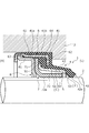
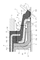
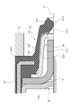
- FIG. 1 is a cross-sectional view illustrating a lip-type shaft sealing device according to a first embodiment of the present invention. It is sectional drawing which expands and shows the path
- Embodiment 1 An embodiment for implementing the lip-type shaft sealing device according to the present invention will be described below based on Embodiment 1.
- the lip-type shaft sealing device will be described with reference to FIGS.
- the front side of the paper of FIG. 1 is referred to as the front side, the upper and lower left and right directions as viewed from the front side, the left side is the atmosphere side A, the right side is the inboard side L, the upper side is the outer diameter side, and the lower side is the inner diameter side. It will be described as.
- the lip-type shaft sealing device 1 includes a first lip 4 and a second lip 7, and a first backup that plays a role of assisting the strength of the first lip 4 and the second lip 7 and restricting the movement thereof.
- a ring 5, a second backup ring 8 and a skeletal ring 6, and these are unitized and mounted in the housing 3 to seal the annular gap between the shaft 2 and the housing 3. Prevent leakage of the refrigerant inside L.
- the refrigerant an alternative chlorofluorocarbon such as HCFC or HFC, carbon dioxide, or the like is used.
- the first backup ring 5 is the backup ring and the lip support of the present invention
- the skeleton ring 6 is the lip support of the present invention.
- the first lip 4 is a rubber member such as hydrogenated nitrile rubber, nitrile rubber, fluorine rubber, ethylene propylene rubber, etc., and has a main body 41 on the outer diameter side and a leg extending from the main body 41 to the inboard side L. 43 and a tip portion 42 on the inner diameter side of the leg portion 43.
- the main body 41 of the first lip 4 surrounds the second lip 7, the first backup ring 5, and the second backup ring 8 on the outer diameter side.
- a metal skeletal ring 6 having an inverted U-shaped cross section when viewed in section is provided inside.
- leg portion 43 is supported by the extending portion 52 of the first backup ring 5 from the inner diameter side, which is behind the surface of the inboard side L that receives the pressure of the refrigerant, and the tip portion 42 that is not supported by the extending portion 52. Is easy to move in the radial direction, and the sliding portion 42 a of the distal end portion 42 slides with respect to the shaft 2. Note that a space formed on the back side of the distal end portion 42 and partitioned by the distal end portion 42 and the shaft 2 is referred to as a distal end portion rear side space F.
- the second lip 7 is a member made of PTFE, and has a root portion 71 and an extended portion 72 extending in the inner diameter direction.
- the root portion 71 is formed by the base portion 51 of the first backup ring 5 disposed on the inboard side L and the second backup ring 8 disposed on the atmosphere side A, and is located on the outer diameter side of the first backup ring 5. It is held in a state of being sandwiched in the axial direction by the base 41 b of the one lip 4.
- the outer periphery of the root 71 of the second lip 7 and the outer periphery of the outer diameter portion 81 of the second backup ring 8 abut against the annular fitting recess 41 a on the inner diameter side of the main body 41 of the first lip 4,
- the root 71 of the second lip 7 and the second backup ring 8 are accommodated in the fitting recess 41 a of the first lip 4.
- the base 41 b of the first lip 4, the root 71 of the second lip 7, and the outer diameter 81 of the second backup ring 8 are sandwiched and held by a pair of legs 62 and 63 of the skeletal ring 6.
- the extending portion 72 extends to the inside L of the machine, and slides on the shaft 2 at a sliding portion 72a of the extending portion 72. It is preferable that the first lip 4 is more permeable to the refrigerant than the second lip 7.
- the first backup ring 5 is a metal member having a substantially S-shape in cross-section, extends in the outer diameter direction, and functions as a holding / fixing portion.
- An extended portion 52 inclined at a small angle with respect to the end portion 53 and an end portion 53 extending from the inner diameter end to the inner diameter side of the extended portion 52 are provided.
- the through-holes 54 as communication means are formed equally. Further, since the opening of the through hole 54 has a circular shape, the strength of the first backup ring 5 itself can be easily maintained.
- the space defined by the first backup ring 5, the second lip 7, and the shaft 2 is defined as an intermediate chamber C, and the intermediate chamber C is continuous with the front end rear side space F.
- the skeletal ring 6 includes a base 61 and legs 62 and 63 extending radially inward from ends on the inboard side L and the atmosphere A of the base 61, and the leg 62 extends circumferentially.
- Through holes 64 as communication means are equally arranged and formed. Further, since the opening of the through hole 64 has a circular shape, the strength of the skeleton ring 6 itself can be easily maintained.
- the mechanism of the shaft sealing mainly the flow of the refrigerant from the inside L of the machine to the space F on the back side of the front end will be described.
- the distal end portion 42 of the first lip 4 receives pressure from the refrigerant and is pressed against the rotating shaft to prevent the refrigerant from moving toward the front end rear space F side.
- the second lip 7 prevents the refrigerant from leaking to the atmosphere side A
- the refrigerant passing between the shaft 2 and the distal end portion 42 and the first lip 4 are filled with a small amount of refrigerant.
- the amount of the refrigerant passing through the space between the shaft 2 and the distal end portion 42 and flowing into the distal end portion rear side space F is relatively small or substantially constant, the description thereof will be omitted.
- the second path P2 passing through the hole 54, the intermediate chamber C, and the front end rear space F in order, the main body 41, the through hole 64, the base 41b, the base 51 of the first backup ring 5, and the root 71 of the second lip 7.
- the third path P3 passing in the order of the intermediate chamber C and the front end rear space F, the leg 43, the base 41b, the base 51 of the first backup ring 5 and the first path 43 without passing through the through holes 54 and 64.
- the intermediate chamber C is spatially wider than the space F on the rear side of the front end portion, the refrigerant passing through the above four paths is stored in the intermediate chamber C, so that the pressure generated in the intermediate chamber C is uniform. And the back pressure can be stably held in the space F on the back side of the distal end portion.
- the internal pressure rises in the front end portion rear side space F the pressure difference between the pressure inside the machine L and the internal pressure of the front end portion rear side space F is reduced, and the force applied from the machine inside L to the inside diameter side in the sliding portion 42a, A force that acts on the outer diameter side from the rear space F on the distal end portion to push it back acts (see the white arrow in FIG.
- the load of the sliding portion 42 a on the shaft 2 can be reduced.
- the pressure in the inboard side L instantaneously increases, the refrigerant quickly reaches the front end rear space F through the second path P2 and the third path P3 in addition to the first path P1, and the internal pressure is reduced. Therefore, the load of the sliding portion 42a on the shaft 2 can be reduced in response to the rise in the pressure inside the machine L.
- only one of the through holes 54 and 64 may be formed.
- the second path P2 passing through the through hole 54 has a short distance through which the refrigerant passes through the first lip 4, so that the through hole 54 is formed. Is preferred.
- the refrigerant in the inside L of the machine can be cooled. Since it is easy to reach the front end rear space F through the through holes 54 and 64, the internal pressure standing in the front rear space F increases, and the internal pressure of the inboard side L and the internal pressure of the front rear space F increase. The differential pressure can be reduced, and the load on the sliding portion 42a with respect to the shaft of the first lip 4 can be reduced.
- the intermediate chamber C is defined and defined by the first backup ring 5, the second lip 7, and the shaft 2, and is continuous with the space F on the rear side of the front end portion. Therefore, the pressure generated in the intermediate chamber C can be equalized, and the back pressure can be stably maintained in the space F on the front end rear surface side.
- the through-hole 54 is formed in the extending portion 52 of the first backup ring 5, the through-hole 54 is connected to the intermediate chamber C, so that the refrigerant that has passed through the first lip 4 is quickly intermediated. It is designed to enter room C.
- first lip 4 is a rubber lip seal and the second lip 7 is a PTFE (polytetrafluoroethylene) lip seal
- first lip 4 can allow a refrigerant to pass therethrough, and the second lip 7
- the refrigerant can be prevented from leaking to the atmosphere side A, so that the back pressure applied to the front end portion rear side space F can be reliably held.
- first backup ring 5 and the skeleton ring 6 have the plurality of through holes 54 and 64 formed in the circumferential direction, a large amount of refrigerant can be reliably supplied from the many through holes to the front-end rear space F. Can be sent to
- the back pressure is uniformly applied to the front end rear side space F in the circumferential direction. Can be given.
- a lip-type shaft sealing device according to a second embodiment will be described with reference to FIG. Note that the same components as those shown in the above-described embodiment are denoted by the same reference numerals, and redundant description will be omitted.
- the first backup ring 5 is provided inside the leg 43X of the first lip 4X along the longitudinal direction of the leg 43X.
- a through hole 54 is formed in the extending portion 52 of the first backup ring 5, but a through hole is not formed in the leg 62X of the skeleton ring 6X.
- a space defined by the leg 43X of the first lip 4X, the second lip 7, and the shaft 2 is defined as an intermediate chamber C '.
- a lip-type shaft sealing device according to a third embodiment will be described with reference to FIG. Note that the same components as those shown in the above-described embodiment are denoted by the same reference numerals, and redundant description will be omitted.
- a groove 44 ⁇ / b> Y is formed on the inner diameter side of the leg 43 ⁇ / b> Y of the first lip 4 ⁇ / b> Y as communication means extending in the axial direction and concave in the outer diameter direction. It has an opening width of a predetermined dimension and is formed so as to be evenly distributed in the circumferential direction. Further, no through hole is formed in the extending portion 52Y of the first backup ring 5Y and the leg portion 62Y of the skeleton ring 6Y. Note that a through-hole may be formed in the extension portion 52Y or the leg portion 62Y.
- the pressure inside the cabin L increases instantaneously, in addition to the first path P1 described in the first embodiment, the pressure quickly passes through a path that passes through the leg 43Y, the groove 44Y, and the front-end rear space F in this order. Since the refrigerant reaches the front end portion rear side space F and the internal pressure rises, the load on the sliding portion 42aY of the front end portion 42Y with respect to the shaft 2 can be reduced in response to the pressure increase inside the machine L.
- a lip-type shaft sealing device according to a fourth embodiment will be described with reference to FIG. Note that the same components as those shown in the above-described embodiment are denoted by the same reference numerals, and redundant description will be omitted.
- a groove 55 ⁇ / b> Z is formed on the outer diameter side of the first backup ring 5 ⁇ / b> Z as communication means extending in the axial direction and concave in the inner diameter direction from the extending portion 52 ⁇ / b> Z to the terminal end portion 53 ⁇ / b> Z.
- the groove 55Z has an opening width of a predetermined dimension in the circumferential direction, and is formed so as to be evenly distributed in the circumferential direction.
- no through hole is formed in the extending portion 52Z of the first backup ring 5Z and the leg portion 62Z of the skeleton ring 6Z. Note that a through hole may be formed in the extension 52Z or the leg 62Z.
- the pressure in the inboard side L rises momentarily, in addition to the first path P1 described in the first embodiment, the pressure quickly passes through a path passing through the leg 43, the groove 55Z, and the front end space F in the order. Since the refrigerant reaches the front end portion rear side space F and the internal pressure rises, the load on the sliding portion 42a of the front end portion 42 with respect to the shaft 2 can be reduced in response to the increase in the pressure inside the machine L.
- the through hole 54 is formed at one place in a cross-sectional view.
- the present invention is not limited to this, and the strength of the first backup ring 5 itself is significantly impaired. It may be formed in two or more places as long as it is not present.
- the through-hole 64 is formed at one position in the leg portion 62 of the skeleton ring 6 in a cross-sectional view.
- the present invention is not limited to this, and two holes are provided as long as the strength of the skeleton ring 6 itself is not significantly impaired. It may be formed as described above.
- the first lip 4 is described as a rubber member such as hydrogenated nitrile rubber, nitrile rubber, fluorine rubber, ethylene propylene rubber, but is not limited thereto. Any material can be used as long as it can seal the shaft.
- the second lip 7 is described as a member made of PTFE, the present invention is not limited to this. Any material may be used as long as the material has no permeability to the refrigerant and can seal the refrigerant.
- lip-type shaft sealing device has been described as including two seal lips, the present invention is not limited to this, and may include three or more lips.
Landscapes
- Engineering & Computer Science (AREA)
- General Engineering & Computer Science (AREA)
- Mechanical Engineering (AREA)
- Sealing With Elastic Sealing Lips (AREA)
- Sealing Devices (AREA)
Abstract
L'objectif de la présente invention est de fournir un dispositif d'étanchéité d'arbre de type à lèvre avec lequel il est possible qu'une charge résultant d'une pression à l'intérieur d'un intérieur de machine et agissant sur une partie coulissante d'une première lèvre, qui coulisse contre un arbre, soit réduite en utilisant la propriété selon laquelle la première lèvre peut permettre la transmission d'un fluide frigorigène. Dans un dispositif d'étanchéité d'arbre de type à lèvre (1) destiné à assurer l'étanchéité d'un espace annulaire entre un arbre (2) et un carter (3), qui tournent l'un par rapport à l'autre, au moyen d'une première lèvre (4) sur un côté intérieur de machine (L), maintenue par des corps de support de lèvre métalliques (5, 6), et d'une seconde lèvre (7) sur un côté atmosphère A : la première lèvre (4) est un élément comprenant un matériau apte à permettre la transmission d'un fluide frigorigène ; et un moyen de communication (54, 64) permettant au fluide frigorigène de passer à travers vers un espace latéral de surface arrière de partie d'extrémité distale (F) de la première lèvre (4) est formé dans au moins l'un des corps de support de lèvre (5, 6), ou la première lèvre (4).
Priority Applications (4)
| Application Number | Priority Date | Filing Date | Title |
|---|---|---|---|
| US17/272,208 US20210317915A1 (en) | 2018-09-14 | 2019-09-13 | Lip type shaft sealing device |
| CN201980056497.XA CN112639338A (zh) | 2018-09-14 | 2019-09-13 | 唇型轴封装置 |
| EP19860283.1A EP3851708A1 (fr) | 2018-09-14 | 2019-09-13 | Dispositif d'étanchéité d'arbre de type à lèvre |
| JP2020546221A JPWO2020054843A1 (ja) | 2018-09-14 | 2019-09-13 | リップ型軸封装置 |
Applications Claiming Priority (2)
| Application Number | Priority Date | Filing Date | Title |
|---|---|---|---|
| JP2018-172496 | 2018-09-14 | ||
| JP2018172496 | 2018-09-14 |
Publications (1)
| Publication Number | Publication Date |
|---|---|
| WO2020054843A1 true WO2020054843A1 (fr) | 2020-03-19 |
Family
ID=69777654
Family Applications (1)
| Application Number | Title | Priority Date | Filing Date |
|---|---|---|---|
| PCT/JP2019/036079 Ceased WO2020054843A1 (fr) | 2018-09-14 | 2019-09-13 | Dispositif d'étanchéité d'arbre de type à lèvre |
Country Status (5)
| Country | Link |
|---|---|
| US (1) | US20210317915A1 (fr) |
| EP (1) | EP3851708A1 (fr) |
| JP (1) | JPWO2020054843A1 (fr) |
| CN (1) | CN112639338A (fr) |
| WO (1) | WO2020054843A1 (fr) |
Families Citing this family (1)
| Publication number | Priority date | Publication date | Assignee | Title |
|---|---|---|---|---|
| CN115112069B (zh) * | 2022-07-20 | 2025-07-01 | 合肥东昇智能装备股份有限公司 | 一种镀膜检测装置 |
Citations (6)
| Publication number | Priority date | Publication date | Assignee | Title |
|---|---|---|---|---|
| JPH0271171U (fr) * | 1988-11-16 | 1990-05-30 | ||
| JPH10325466A (ja) * | 1997-05-23 | 1998-12-08 | Nok Corp | 密封装置 |
| JP2001254841A (ja) * | 2000-03-10 | 2001-09-21 | Eagle Ind Co Ltd | リップ型シールの装着構造 |
| JP2005042881A (ja) * | 2003-07-25 | 2005-02-17 | Denso Corp | リップ型シールによる軸封構造 |
| JP2009024541A (ja) | 2007-07-18 | 2009-02-05 | Sanden Corp | 軸シール |
| WO2012017726A1 (fr) * | 2010-08-06 | 2012-02-09 | イーグル工業株式会社 | Joint d'étanchéité à lèvre |
Family Cites Families (1)
| Publication number | Priority date | Publication date | Assignee | Title |
|---|---|---|---|---|
| JP2003120823A (ja) * | 2001-10-19 | 2003-04-23 | Eagle Ind Co Ltd | シール装置 |
-
2019
- 2019-09-13 CN CN201980056497.XA patent/CN112639338A/zh not_active Withdrawn
- 2019-09-13 EP EP19860283.1A patent/EP3851708A1/fr not_active Withdrawn
- 2019-09-13 WO PCT/JP2019/036079 patent/WO2020054843A1/fr not_active Ceased
- 2019-09-13 JP JP2020546221A patent/JPWO2020054843A1/ja active Pending
- 2019-09-13 US US17/272,208 patent/US20210317915A1/en not_active Abandoned
Patent Citations (6)
| Publication number | Priority date | Publication date | Assignee | Title |
|---|---|---|---|---|
| JPH0271171U (fr) * | 1988-11-16 | 1990-05-30 | ||
| JPH10325466A (ja) * | 1997-05-23 | 1998-12-08 | Nok Corp | 密封装置 |
| JP2001254841A (ja) * | 2000-03-10 | 2001-09-21 | Eagle Ind Co Ltd | リップ型シールの装着構造 |
| JP2005042881A (ja) * | 2003-07-25 | 2005-02-17 | Denso Corp | リップ型シールによる軸封構造 |
| JP2009024541A (ja) | 2007-07-18 | 2009-02-05 | Sanden Corp | 軸シール |
| WO2012017726A1 (fr) * | 2010-08-06 | 2012-02-09 | イーグル工業株式会社 | Joint d'étanchéité à lèvre |
Also Published As
| Publication number | Publication date |
|---|---|
| EP3851708A1 (fr) | 2021-07-21 |
| CN112639338A (zh) | 2021-04-09 |
| JPWO2020054843A1 (ja) | 2021-08-30 |
| US20210317915A1 (en) | 2021-10-14 |
Similar Documents
| Publication | Publication Date | Title |
|---|---|---|
| JP6427778B2 (ja) | メカニカルシール | |
| US10738891B2 (en) | Seal assembly for a rotating member | |
| KR102225661B1 (ko) | 압력-작동가능한 회전 씰을 구비한 회전 씰 조립체, 및 회전 씰(Rotary Seal assembly with pressure-activatable rotary seal, and rotary seal) | |
| KR20210045487A (ko) | 슬라이딩 부재 | |
| JP2016008685A (ja) | 密封装置 | |
| CN109983243B (zh) | 烧结轴承 | |
| JP6328658B2 (ja) | メカニカルシール | |
| AU2016215900B2 (en) | Mechanical seal | |
| JP5608464B2 (ja) | ダブルシール構造 | |
| JPWO2020054843A1 (ja) | リップ型軸封装置 | |
| JPWO2019031377A1 (ja) | セグメントシール | |
| WO2016013444A1 (fr) | Joint d'étanchéité mécanique | |
| WO2018207746A1 (fr) | Joint mécanique | |
| JP2008296626A (ja) | ブッシュ軸受及びそれを用いた自動車のラックピニオン式油圧パワーステアリング装置 | |
| CN105987082B (zh) | 轴承、特别是车辆轴承 | |
| US11608885B2 (en) | Planet carrier with flexible bolt and stiffening rib | |
| JP2019100372A (ja) | 回転・揺動用シールの供回り抑制機構 | |
| US20240200660A1 (en) | Sealing device | |
| WO2020230545A1 (fr) | Dispositif de joint d'étanchéité | |
| JP2015143549A (ja) | シリンダ装置 | |
| JP5178385B2 (ja) | 回転軸シール装置 | |
| JP2014196798A (ja) | 転がり軸受 | |
| JP2008025392A (ja) | クランクシャフト用オイルシールの取り付け構造 | |
| JP7183296B2 (ja) | フローティングリングシール | |
| JP2023091263A (ja) | メカニカルシール |
Legal Events
| Date | Code | Title | Description |
|---|---|---|---|
| 121 | Ep: the epo has been informed by wipo that ep was designated in this application |
Ref document number: 19860283 Country of ref document: EP Kind code of ref document: A1 |
|
| ENP | Entry into the national phase |
Ref document number: 2020546221 Country of ref document: JP Kind code of ref document: A |
|
| NENP | Non-entry into the national phase |
Ref country code: DE |
|
| ENP | Entry into the national phase |
Ref document number: 2019860283 Country of ref document: EP Effective date: 20210414 |