WO2020054911A1 - 엘리베이터용 리니어 모터 - Google Patents
엘리베이터용 리니어 모터 Download PDFInfo
- Publication number
- WO2020054911A1 WO2020054911A1 PCT/KR2018/014332 KR2018014332W WO2020054911A1 WO 2020054911 A1 WO2020054911 A1 WO 2020054911A1 KR 2018014332 W KR2018014332 W KR 2018014332W WO 2020054911 A1 WO2020054911 A1 WO 2020054911A1
- Authority
- WO
- WIPO (PCT)
- Prior art keywords
- mover
- protruding
- module
- permanent magnets
- teeth
- Prior art date
- Legal status (The legal status is an assumption and is not a legal conclusion. Google has not performed a legal analysis and makes no representation as to the accuracy of the status listed.)
- Ceased
Links
Images





Classifications
-
- B—PERFORMING OPERATIONS; TRANSPORTING
- B66—HOISTING; LIFTING; HAULING
- B66B—ELEVATORS; ESCALATORS OR MOVING WALKWAYS
- B66B11/00—Main component parts of lifts in, or associated with, buildings or other structures
- B66B11/04—Driving gear ; Details thereof, e.g. seals
-
- H—ELECTRICITY
- H02—GENERATION; CONVERSION OR DISTRIBUTION OF ELECTRIC POWER
- H02K—DYNAMO-ELECTRIC MACHINES
- H02K1/00—Details of the magnetic circuit
- H02K1/06—Details of the magnetic circuit characterised by the shape, form or construction
- H02K1/12—Stationary parts of the magnetic circuit
- H02K1/14—Stator cores with salient poles
-
- H—ELECTRICITY
- H02—GENERATION; CONVERSION OR DISTRIBUTION OF ELECTRIC POWER
- H02K—DYNAMO-ELECTRIC MACHINES
- H02K1/00—Details of the magnetic circuit
- H02K1/06—Details of the magnetic circuit characterised by the shape, form or construction
- H02K1/22—Rotating parts of the magnetic circuit
- H02K1/24—Rotor cores with salient poles ; Variable reluctance rotors
-
- H—ELECTRICITY
- H02—GENERATION; CONVERSION OR DISTRIBUTION OF ELECTRIC POWER
- H02K—DYNAMO-ELECTRIC MACHINES
- H02K41/00—Propulsion systems in which a rigid body is moved along a path due to dynamo-electric interaction between the body and a magnetic field travelling along the path
- H02K41/02—Linear motors; Sectional motors
- H02K41/03—Synchronous motors; Motors moving step by step; Reluctance motors
Definitions
- the present invention relates to a linear motor for an elevator. More specifically, by separating and installing a plurality of stators installed in the hoistway so that a gap exists between them, not only is it easy to manufacture and install, but also can significantly shorten the installation work time, and separate connection work is unnecessary during the installation work. In addition, it is easy to correct the error by adjusting the gap of the stator, and even in the case of repair and replacement work for the stator, it is possible to simply remove and replace the stator in some sections, so that repair work and other inspection work can be performed very quickly and conveniently It relates to a linear motor for an elevator.
- An elevator is a device that elevates passengers or cargo along a hoistway formed along a vertical direction of a building
- a general elevator is an elevator car disposed to be able to elevate within a hoistway, and a counterweight connected by an elevator car and a wire rope.
- the so-called rope-type elevator having a hoisting machine for driving the elevator car and the counterweight up and down by frictionally contacting the wire rope on the upper side of the hoistway to rotate forward and backward.
- the rope type elevator has a problem in terms of efficiency and stability because the length of the rope becomes longer when the height of the elevator is high because the elevator car is suspended from the rope.
- the height of the hoistway is also limited due to the weight and safety issues of the ropes and accessory parts, and for this reason, the height of the building is also limited.
- an elevator applicable to a high-rise building can operate multiple elevator cars simultaneously within a single passageway, and the elevator car can move freely in the vertical / horizontal direction along the three-dimensional passageway inside the building. It should be able to demonstrate its function as a comprehensive transportation system that can be used in connection with buildings and underpasses.
- the elevator currently used adopts an elevator driving method by traction of the rope, so it is necessary to consider the load and vibration characteristics of the elevator car in proportion to the number of floors when designing, and it is impossible to change the vertical / horizontal direction of the elevator car. Since it has the limitations of, the alternative structure to overcome this should be urgently prepared.
- the linear motor type elevator is generally installed by installing a stator along a guide rail of a hoistway and installing a mover in an elevator car, and is configured to move the elevator car vertically and horizontally using electromagnetic force of the stator and the mover.
- the stator is generally formed as one integral type along the guide rail, and as the stator is integrally formed in this way, the installation work is very difficult and takes a long time, and the arrangement state in the entire section is due to tolerances, etc. It is difficult to maintain accurately, and accordingly, an error occurs during an elevator driving process or a problem such as failure to maintain a stable driving state occurs.
- the present invention was invented to solve the problems of the prior art, and the object of the present invention is to separate and install a plurality of stators installed in a hoistway so that a gap exists between each other, thereby facilitating production and installation work, as well as installation time. It is to provide a linear motor for an elevator that can be significantly shortened.
- Another object of the present invention is a separate connection operation is unnecessary during the installation operation, so that the installation operation is easy, and the error is easily corrected by adjusting the gap of the stator. It is to provide a linear motor for elevators that can be removed and replaced to perform repair work and other inspection work very quickly and conveniently.
- Another object of the present invention is that even if the amount of thermal deformation of the stator increases due to a change in temperature conditions according to the environment, the amount of thermal deformation can be compensated by the gap of the stator, thereby minimizing the overall dimensional change, and thus always stable It is to provide a linear motor for an elevator that can maintain driving performance.
- Another object of the present invention even if a gap exists between a plurality of stators installed in a hoistway, so that the magnetic flux flow does not pass through the gap, the magnetic flux flow is always stably and smoothly, thereby stably driving the propulsive force by electromagnetic force. It is to provide a linear motor for an elevator that can be generated.
- the present invention is a linear motor for an elevator that includes a stator module installed along a driving direction of an elevator car and a mover module coupled to an elevator car so as to face each other on both sides of the stator module, wherein the stator module is an elevator
- a plurality of stators along the driving direction of the car are installed in a spaced apart arrangement so as to have a gap, the mover module and the stator module flow of magnetic flux formed through the mover module and the stator module passes through the gap of the stator It provides a linear motor for an elevator characterized in that it is formed so as not to be made in the form.
- the plurality of stators each include a central field iron core portion formed along the driving direction of the elevator car, and first and second protruding portions respectively protruding a plurality of both sides of the central field iron core portion.
- the first and second protruding portions may be disposed to be offset from each other on both sides of the central field iron core portion.
- the plurality of first protrusions may be spaced apart to have the same spacing
- the plurality of second protrusions may be spaced apart at the same spacing so as to be positioned between the spacings of the first protrusions.
- a plurality of the stators may be arranged to maintain the same spacing between two stators adjacent to each other by adjusting the gap therebetween.
- the mover module the stator module is disposed to be opposed to each other on both sides, the intermediate slot is formed in the middle region and the first and second protruding toward the stator module in both regions around the middle slot
- Two armature iron cores on which mover teeth are formed A magnet module comprising at least one permanent magnet mounted opposite to each other on the first and second mover teeth of the two armature iron cores and disposed to have the same spacing as the first and second protrusions; And an armature winding wound around the armature iron core through the intermediate slot.
- the magnet module may be formed in a form in which permanent magnets having different polarities are alternately arranged in a row at the same spacing as the pitch P of the first and second protrusions.
- the magnet module alternates each other with a permanent magnet having the same polarity with each other, and a protruding pole disposed in an area adjacent to the permanent magnet is the same as the protruding pitch P, which is the spacing between the first and second protruding portions. It can be formed in a form arranged in line.
- the arrangement interval between the permanent magnets mounted on the first mover teeth adjacent to the second mover teeth and the permanent magnets adjacent to the first mover teeth among the permanent magnets mounted on the second mover teeth is the It may be formed by m times the pitch P of the protruding poles P (where m is a natural number).
- the spacing between the protrusions adjacent to the second mover tooth among the protrusions mounted on the first mover tooth and the protrusions adjacent to the first mover tooth among the protrusions mounted on the second mover tooth is the protrusion pitch P ) M times (where m is a natural number).
- the distance from the center of the first mover tooth of the armature iron core to the center of the second mover tooth may be formed at n times (where n is a natural number) of the protruding pitch P.
- the present invention is a linear motor for an elevator that includes a stator module installed along the driving direction of the elevator car and a mover module coupled to the elevator car so as to face each other on both sides of the stator module, wherein the stator module Is installed in a form arranged in a row spaced apart so as to have a plurality of stators, a plurality of the stator, respectively, on the both sides of the center field iron core portion and the center field iron core portion disposed long along the driving direction of the elevator car
- Each of the first and second protruding portions are formed to be protruded so as to be offset from each other at equal intervals, and the mover module is disposed opposite to each other on the stator module, and an intermediate slot is formed in the middle region.
- Protruding toward the stator module in both regions around the middle slot Is two armature iron cores on which the first and second mover teeth are formed; A magnet module mounted opposite to each other on first and second mover teeth of the two armature iron cores; And an armature winding wound on the armature iron core through the intermediate slot, wherein the magnet module has a permanent magnet having a different polarity from each other, and an arrangement gap equal to a protruding pitch P, which is an arrangement spacing of the first and second protruding parts.
- the tooth pitch Pt which is the arrangement interval of the first and second mover teeth, is the It provides a linear motor for elevators, characterized in that formed at (2n-1) times (where n is a natural number of 2 or more) of the protruding pitch P.
- the tooth pitch Pt is (2n) times the protruding pitch P (where n is a natural number of 2 or more). It can be formed of.
- the spacing between the permanent magnets may be formed by (2m-1) times (where m is a natural number) of the protruding pitch P.
- the spacing between permanent magnets may be formed by (2m) times (where m is a natural number) of the protruding pitch P.
- the present invention is a linear motor for an elevator that includes a stator module installed along the driving direction of the elevator car and a mover module coupled to the elevator car so as to face each other on both sides of the stator module, wherein the stator module Is installed in a form arranged in a row spaced apart so as to have a plurality of stators, a plurality of the stator, respectively, on the both sides of the center field iron core portion and the center field iron core portion disposed long along the driving direction of the elevator car
- Each of the first and second protruding portions are formed to be protruded so as to be offset from each other at equal intervals, and the mover module is disposed opposite to each other on the stator module, and an intermediate slot is formed in the middle region.
- Protruding toward the stator module in both regions around the middle slot Is two armature iron cores on which the first and second mover teeth are formed; A magnet module mounted opposite to each other on first and second mover teeth of the two armature iron cores; And an armature winding wound around the armature iron core through the intermediate slot, wherein the magnet module includes permanent magnets having the same polarity with each other, and protruding poles disposed in regions adjacent to the permanent magnets are the first and second protruding poles.
- the first Provides a linear motor for an elevator, characterized in that the tooth pitch (Pt), which is the spacing between the first and second mover teeth, is formed by (2n-1) times (where n is a natural number greater than or equal to 2) of the protruding pitch P. do.
- the tooth pitch Pt is (2n) times the protruding pitch P (where n is 2 or more) Natural water).
- both the permanent magnet mounted on the first mover tooth and the object closest to the second mover value among the permanent magnets and protrusions mounted on the second mover tooth, and the object closest to the first mover value among the permanent mover and stone poles mounted on the second mover tooth are the same as the permanent magnets or the protruding poles, the spacing between the permanent magnets or the protruding poles may be formed by (2m-1) times the protruding pitch P (where m is a natural number).
- the object closest to the second mover value is If one is a permanent magnet and the other is a different pole, the spacing between the permanent magnet and the pole may be formed by (2m) times (where m is a natural number) of the pitch P of the pole.
- first and second mover teeth may be formed to have the same width that protrudes toward the stator module.
- the present invention is a linear motor for an elevator that includes a stator module installed along the driving direction of the elevator car and a mover module coupled to the elevator car so as to face each other on both sides of the stator module, wherein the stator module Is installed in a form arranged in a row spaced apart so as to have a plurality of stators, a plurality of the stator, respectively, on the both sides of the center field iron core portion and the center field iron core portion disposed long along the driving direction of the elevator car
- Each of the first and second protruding portions are formed to be protruded so as to be offset from each other at equal intervals, and the mover module is disposed opposite to each other on the stator module, and an intermediate slot is formed in the middle region.
- Protruding toward the stator module in both regions around the middle slot Is two armature iron cores on which the first and second mover teeth are formed;
- a magnet module comprising at least one permanent magnet mounted opposite to each other on the first and second mover teeth of the two armature iron cores and disposed to have the same spacing as the first and second protrusions;
- an armature winding wound on the armature iron core through the intermediate slot wherein the magnet module has a permanent magnet having a different polarity from each other, and an arrangement gap equal to a protruding pitch P, which is an arrangement spacing of the first and second protruding parts.
- the number of permanent magnets of the magnet module is set to (n + 4) or more, where n is an integer of 0 or more to provide a linear motor for an elevator.
- the number of permanent magnets of the magnet module may be set to 3 or more.
- the present invention is a linear motor for an elevator that includes a stator module installed along the driving direction of the elevator car and a mover module coupled to the elevator car so as to face each other on both sides of the stator module, wherein the stator module Is installed in a form arranged in a row spaced apart so as to have a plurality of stators, a plurality of the stator, respectively, on the both sides of the center field iron core portion and the center field iron core portion disposed long along the driving direction of the elevator car
- Each of the first and second protruding portions are formed to be protruded so as to be offset from each other at equal intervals, and the mover module is disposed opposite to each other on the stator module, and an intermediate slot is formed in the middle region.
- Protruding toward the stator module in both regions around the middle slot Is two armature iron cores on which the first and second mover teeth are formed;
- a magnet module comprising at least one permanent magnet mounted opposite to each other on the first and second mover teeth of the two armature iron cores and disposed to have the same spacing as the first and second protrusions;
- an armature winding wound around the armature iron core through the intermediate slot wherein the magnet module includes permanent magnets having the same polarity with each other, and protruding poles disposed in regions adjacent to the permanent magnets, the first and second.
- nP + bw ⁇ d ⁇ (n + 1) P + bw the total number of permanent magnets and protrusions of the magnet module is set to (n + 4) or greater, where n is an integer greater than or equal to 0 It provides a linear motor for elevators, characterized in that.
- the total number of permanent magnets and protrusions of the magnet module may be set to 3 or more.
- a plurality of the stators are arranged between the first and second protruding portions adjacent to each other among the first and second protruding portions formed in two adjacent stators formed by adjusting the gap d therebetween. It may be installed to be maintained at n times (where n is a natural number) of P).
- the arrangement interval between the permanent magnets mounted on the first mover teeth adjacent to the second mover teeth and the permanent magnets adjacent to the first mover teeth among the permanent magnets mounted on the second mover teeth is the It may be formed at n times the pitch of the protruding poles P (where n is a natural number).
- the spacing between the protrusions adjacent to the second mover tooth among the protrusions mounted on the first mover tooth and the protrusions adjacent to the first mover tooth among the protrusions mounted on the second mover tooth is the protrusion pitch P ) N times (where n is a natural number).
- the present invention by separating and installing a plurality of stators installed in the hoistway so that a gap exists between each other, it is possible to not only facilitate manufacturing and installation work, but also significantly reduce installation work time.
- the amount of thermal deformation of the stator increases due to a change in temperature conditions according to the environment, the amount of thermal deformation can be compensated by the gap of the stator, thereby minimizing the overall dimensional change, and accordingly, maintaining stable driving performance. It has an effect.
- the magnetic flux flow is always stably and smoothly made by preventing the magnetic flux flow from passing through the gap, thereby stably generating propulsion by electromagnetic force.
- FIG. 1 is a view conceptually showing the installation structure of a linear motor for an elevator according to an embodiment of the present invention
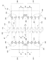
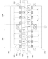
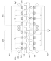
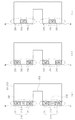
- Figure 2 is a cross-sectional view taken along the line "A-A" of Figure 1 to explain the internal structure of the elevator linear motor according to an embodiment of the present invention
- FIG. 3 is a view conceptually showing the configuration of a stator module of an elevator linear motor according to an embodiment of the present invention
- FIG. 4 is a view conceptually showing the configuration of the mover module of the elevator linear motor according to an embodiment of the present invention
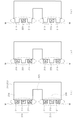
- FIG. 6 and 7 is a diagram conceptually showing the magnetic flux flow state of the linear motor for an elevator according to an embodiment of the present invention
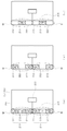
- FIGS. 8 to 10 are views exemplarily showing various forms of the mover module according to an embodiment of the present invention.
- FIG. 11 is a view for explaining a magnetic flux flow method for the basic structure of a linear motor according to an embodiment of the present invention
- FIG. 12 is a view for explaining a problem of magnetic flux flow that may occur in the basic structure of a linear motor according to an embodiment of the present invention
- FIG. 13 is a view for explaining the basic structure of a linear motor that solves the problem of magnetic flux flow shown in FIG. 12;
- FIG. 14 is a view for explaining the permanent magnet arrangement structure of the mover module according to an embodiment of the present invention.
- 17 is a view for explaining the relationship between the gap size of the stator module and the number of permanent magnets according to an embodiment of the present invention.
- FIG. 18 is a view for explaining a winding method for the armature winding of the mover module according to an embodiment of the present invention
- 19 is a view schematically showing another form of a linear motor according to an embodiment of the present invention.
- FIG. 1 is a diagram conceptually showing an installation structure of an elevator linear motor according to an embodiment of the present invention
- FIG. 2 is a view illustrating an internal structure of an elevator linear motor according to an embodiment of the present invention
- 3 is a cross-sectional view taken along the line “AA”
- FIG. 3 is a diagram conceptually showing a configuration for a stator module of an elevator linear motor according to an embodiment of the present invention
- FIG. 4 is a view showing an embodiment of the present invention.
- It is a diagram conceptually showing the configuration of the mover module of the linear motor for an elevator according to the present invention
- FIG. 5 is a view for explaining the principle of magnetic flux flow of the linear motor for an elevator according to an embodiment of the present invention.
- the linear motor for an elevator is a device capable of more conveniently performing an installation operation and a maintenance operation, and the stator module 40 that is long disposed in a hoistway along the traveling direction of the elevator car 10 And, it comprises a mover module 50 coupled to the elevator car 10 so as to face each other on both sides of the stator module 40 along the longitudinal direction of the stator module 40.
- a hoistway in which the elevator car 10 can move is installed inside the building.
- the hoistway may be installed not only vertically but also in a horizontal direction and inclined direction.
- the elevator car 10 moves along the hoistway through a linear motor or the like.
- a guide rail 30 may be installed on the hoistway wall 20 of the hoistway along the direction of the hoistway, and when the guide rail 30 is installed, the elevator car 10 moves along the guide rail 30 within the hoistway However, at this time, the elevator car 10 is moved by the linear motor 60.
- the linear motor 60 includes a stator module 40 and a mover module 50, and the stator module 40 is long installed in the hoistway along the traveling direction of the elevator car 10.
- the stator module 40 may be directly installed on the hoistway wall 20 of the hoistway, and when the guide rail 30 is installed on the hoistway wall 20, it is formed long along the guide rail 30 to guide rail 30 It can be installed in a form that is coupled to one end of the.
- the mover module 50 is coupled and fixed to the elevator car 10 to be located on both sides of the stator module 40 along the longitudinal direction of the stator module 40.
- the propulsive force is generated by the electromagnetic force generated between the stator module 40 and the mover module 50, and the mover module 50 and the elevator car 10 move along the stator module 40 by the propulsion force.
- Stator module 40 according to an embodiment of the present invention is installed in a form arranged in a row spaced apart a plurality of stator 100 along the guide rail 30 to have a certain gap (d).
- the stator is not integrally formed, but the stator 100 is provided in a plurality of relatively short lengths and installed in a separate form having a certain gap d.
- the mover module 50 and the stator module 40 are formed such that the flow of magnetic flux formed through the mover module 50 and the stator module 40 does not pass through the gap d of the stator 100. Is formed.
- the flux flow through the mover module 50 and the stator module 40 is formed so as not to pass through the gap d of the stator 100, so that even if the gap d exists in the stator module 40, The magnetic flux flow stably occurs without interruption or sudden drop, and the propulsion by electromagnetic force is stably generated.
- stator module 40 that is installed along the hoistway is separately installed by a plurality of stators 100, it is not only easy to manufacture and install the stator module 40, but also can significantly shorten the installation work time. .
- stator module since the stator module is installed as one unit in the entire section of the hoistway along the guide rail, it is necessary to connect all the stator module connection parts by welding or the like during the installation process. Thereafter, even in the case of repair and replacement work for the stator module, since the repair work must be performed in a manner such as cutting a portion of the integral stator module, there is a problem that the work is very difficult and difficult.
- the stator module 40 separates and installs a plurality of stators 100 in a form having a certain gap (d), so that a separate connection operation is unnecessary during the installation operation.
- a separate connection operation is unnecessary during the installation operation.
- it is easy to correct the error through adjustment of the gap (d) and even when repairing and replacing the stator module 40, the stator 100 in some sections can be simply partially removed and replaced for maintenance work and other checks. Work can also be done very quickly and conveniently.
- the stator module 40 when the stator module 40 is integrally formed long, the amount of thermal deformation of the stator module 40 increases due to a change in temperature conditions according to the environment, and accordingly, a dimensional change occurs, resulting in a problem in driving performance when driving the elevator.
- the stator module 40 since the stator module 40 is separately installed through a plurality of stators 100, the amount of heat distortion can be compensated by the gap d even if thermal deformation occurs. The dimensional change can be minimized, and accordingly, stable driving performance can be maintained at all times.
- each stator 100 may be formed in the same form, and each stator 100 is a central field iron core formed long along the traveling direction of the elevator car 10 It may be configured to include a first protruding portion 120 and a second protruding portion 130, which are respectively protruded on both sides of the central field iron core portion 110 and 110.
- the first protruding portion 120 and the second protruding portion 130 are arranged to be offset from each other along the width direction of the central field iron core portion 110. More specifically, the first protrusion 120 is formed to protrude on one side of the central field iron core 110, and the second protrusion 130 protrudes on the other side of the center field iron core 110. It is formed, the first protrusion 120 and the second protrusion 130 is formed in the same protruding shape.
- the plurality of first protruding parts 120 are spaced apart to have the same disposition gap 2P, and the plurality of second protruding parts 130 are the same disposition spacing so as to be located between the spaced apart spaces of the first protruding parts 120 (2P).
- the second protrusion 130 is located in the middle of the separation interval of the first protrusion 120, the placement distance of the first protrusion 120 and the second protrusion 130 is also the same placement interval P Have
- the stator 100 having the plurality of first protruding parts 120 and the second protruding part 130 has a gap d, and a plurality of stators are arranged in line, and the spacing (2P) of the first protruding parts 120 is arranged. ) Are arranged to remain the same between the two stators 100 adjacent to each other.
- the arrangement spacing 2P of the second protrusion 130 is likewise arranged to remain the same between the two stator 100 adjacent to each other.
- the spacing between the first protrusion 120 and the second protrusion 130 that are disposed to be offset from each other is P
- the spacing between the poles 130 is 2P.
- the bottom first protrusion 120 of the upper stator 100 among the stators 100 adjacent to each other and the lower side The spacing between the uppermost second protruding parts 130 of the stator 100 remains the same as P, and the lowermost second protruding part 130 of the upper stator 100 among the stators 100 adjacent to each other and the lower side
- the spacing between the second protruding poles 130 at the top of the stator 100 is maintained at 2P.
- the gap d between the stators 100 is predetermined in a plurality of stator 100 manufacturing steps, and by setting and installing the gap d according to a predetermined gap d dimension during the stator 100 installation operation, although it is possible to perform a normal installation operation, at this time, an error or the like may occur, so that the spacing (P, 2P) between the first protruding part 120 and the second protruding part 130 is controlled by adjusting the gap d. ) Can be kept constant.
- the gap (d) between the stator 100 which is predetermined in the manufacturing step, is such that the first protrusion 120 and the second protrusion 130 are not removed and some of them exist at a predetermined placement interval P. It may be determined to be smaller than P, which is an arrangement interval between the protrusion 120 and the second protrusion 130. That is, the gap d between the stators 100 may be determined in the range of (0 ⁇ d ⁇ P).
- the mover module 50 is disposed opposite to each other on the stator module 40, and the intermediate slot 203 is formed in the middle region and the stator module 40 is provided in both regions around the middle slot 203.
- Magnet armature including at least one permanent magnet (210) disposed to have the same spacing (P, 2P) as the first and second protrusions (120,130) and the armature iron core through the intermediate slot (203) It may be configured to include an armature winding (230,240) wound on (201,202).
- the two armature iron cores 201 and 202 face each other in a form in which the first armature iron core 201 is disposed on one side of the stator module 40 and the second armature iron core 202 is disposed on the other side of the stator module 40. Can be arranged.
- the magnet modules M are formed to face each other on the first and second mover teeth 204 and 205 respectively formed on the two armature iron cores 201 and 202, respectively.
- the permanent magnet 210 having the same polarity (N-pole or S-pole) and the permanent magnet 210 and the protruding poles 220 disposed in the adjacent regions are the first and second protruding portions 120 and 130 It may be configured to be arranged in a row alternately with each other at the same arrangement interval as the gap pitch P, which is an interval.
- the permanent magnets 210 having the same polarity (N-pole) may be arranged in a line to be spaced apart from each other, and may be configured such that the protruding pole 220 as a simple magnetic material is formed in the region therebetween, wherein the protruding pole 220 is The polarity (N pole) and the opposite polarity (S pole) of the permanent magnet 210 are displayed.
- the magnet module M may be configured such that permanent magnets 210: 211, 212 having different polarities (N poles, S poles) are alternately arranged at the same arrangement interval as the protruding pitch P. (See Figure 8).
- the permanent magnet 210 adjacent to the second mover tooth 205 and the plurality of permanent magnets mounted on the second mover tooth 205 The arrangement interval between the permanent magnets 210 adjacent to the first mover teeth 204 of 210 is formed to be n times (here, n is a natural number) of the protruding pitch P (see FIG. 14).
- n is a natural number
- the spacing between the permanent magnets 210 located may be formed of 3P, which is three times the protruding pitch P.
- the permanent magnet 210 mounted on the first mover tooth 204 and the permanent magnet 210 mounted on the second mover tooth 205 include the first protrusion 120 and the second stone of the stator 100.
- the poles 130 have different relative positions.
- the permanent magnet 210 located in the first mover tooth 204 of the armature iron cores 201 and 202 is positioned on the same straight line as the second protruding part 130, and the armature The permanent magnets 210 located on the second mover teeth 205 of the iron cores 201 and 202 are positioned on the same straight line as the first protrusion 120.
- the flow of magnetic flux by permanent magnets mounted on the first and second mover teeth 204 and 205 of the two armature iron cores 201 and 202 is shown as shown in FIG. 5. That is, since the permanent magnet 210 mounted on the first mover teeth 204 of the second armature iron core 202 is an N-pole, it is formed in a form in which magnetic flux flows out from the permanent magnet 210.
- the permanent magnet 210 of the first armature iron core 201 also exhibits an N-pole, the magnetic flux flow does not flow into the permanent magnet 210 of the first armature iron core 201, and toward the upper and lower protruding poles 220 side. Inflow.
- the protruding pole 220 is relatively closer to the first protruding portion 120, the magnetic flux flows from the first protruding portion 120 toward the protruding pole 220, in this case, the protruding pole 220 is a permanent magnet It acts as the S pole, which is a different polarity from the 210.
- the flow of magnetic flux from the permanent magnet 210 of the second armature iron core 202 is the same polarity (N pole) of the permanent magnet 210 of the first armature core 201, forces that repel each other generate magnetic flux. The branching process of the flow is made more smoothly, and accordingly, the flux flow of the first armature 201 to the protruding pole 220 is made more smoothly.
- the armature windings 230 and 240 are wound in opposite directions from the first mover tooth 204 and the second mover tooth 205.
- Intermediate slots 203 are formed in the center of the mutually opposing surfaces of the two armature iron cores 201 and 202, and the first mover teeth 204 and the second mover teeth 205 are formed on both sides around the middle slot 203.
- the armature windings 230 and 240 may be wound in opposite directions to each other in a form surrounding the first mover tooth 204 and the second mover tooth 205 through the intermediate slot 203.
- Each armature winding (230,240) may be configured to be separately connected in series after being formed in an independently wound form.
- the magnetic flux flow from the plurality of permanent magnets 210 mounted on the second mover teeth 205 of the second armature core 202 It is discharged and flows into the second protruding part 130 of the stator 100, and each magnetic flux flow is branched from the central field iron core part 110 of the stator 100 and then first through the first protruding part 120. It is introduced into the armature iron core 201. At this time, the permanent magnet 210 mounted on the second mover tooth 205 of the first armature iron core 201 flows into the region of the protruding electrode 220. Since the branching and flow of the magnetic flux is based on the principle described with reference to FIG. 5, detailed description is omitted here.
- magnetic flux flow is also discharged from the plurality of permanent magnets 210 mounted on the first mover teeth 204 of the first armature core 201 to flow into the first protrusion 120 of the stator 100,
- Each magnetic flux flow is branched from the central field iron core portion 110 of the stator 100 and then flows into the second armature iron core 202 through the second protruding portion 130. At this time, it flows into the region of the protrusion 220 between the permanent magnets 210 mounted on the first mover teeth 204 of the second armature core 202.
- the flow of magnetic flux is reversed in the first mover value 204 and the second mover value 205 of the armature iron cores 201 and 202 according to the flow of the magnetic flux, and correspondingly, the winding direction of the armature windings 230 and 240 is the first mover value. Since 204 and the second mover value 205 are opposite, the mover module 50 generates the same propulsion force by electromagnetic force.
- the flow of magnetic flux discharged from the permanent magnet 210 of one armature iron core 201,202 is branched from the stator 100 and flows into the other armature iron core 201,202 through the protruding pole portions 120,130.
- the stator 100 is separated through the gap d Even if it is, the magnetic flux flow through the gap d of the stator 100 is prevented, and even if a magnetic flux flow through the gap d occurs, it is very negligible, which is a negligible level. Therefore, even if the stator module 40 according to an embodiment of the present invention separates and installs a plurality of stators 100 through the gap d, the traveling performance of the linear motor is stably maintained because there is no influence on magnetic flux flow. .
- FIG. 7 shows a magnetic flux flow in a state in which the mover module 50 moves with the elevator car 10 by a P interval in the right direction based on the state shown in FIG. 6. 6, the magnetic flux flow appears in the same principle as in FIG. 6, but the overall direction of the magnetic flux flow is formed in the clockwise direction in FIG. 6, while in FIG. In this process, since the direction of the current flowing through the armature windings 230 and 240 is changed, the direction of propulsion by electromagnetic force is always maintained the same regardless of the moving state of the mover module 50.
- FIG 8 to 10 are views exemplarily showing various forms of the mover module according to an embodiment of the present invention.
- the mover module 50 is mounted on the armature iron cores 201 and 202 having the first and second mover teeth 204 and 205 and the first and second mover teeth 204 and 205 as described above. It comprises a magnet module (M) including at least one permanent magnet 210 and the armature winding (230).
- M magnet module
- the magnet module M may be configured in a form in which permanent magnets 210: 211, 212 having different polarities (N-pole, S-pole) are alternately arranged as shown in FIG. 8 (a). .
- a permanent magnet 210 having the same polarity (N-pole) with each other and a protruding electrode 220 disposed in a region adjacent to the permanent magnet 210 are provided. It may be configured in a form arranged alternately with each other. In this case, the arrangement structure of the permanent magnet 210 and the protruding electrode 220 may be set differently as shown in (b) and (c) of FIG. 8 in the first and second mover values 204 and 205.
- the permanent magnet 210 and the protruding poles 220 are arranged to have the same spacing as the protruding pole pitch P.
- the widths of the permanent magnets 210 and the protruding poles 220 are also as shown in FIG. 8. It is formed in the same manner as the protruding pole pitch P, and the plurality of permanent magnets 210 and the protruding poles 220 may be disposed in contact with each other.
- the widths of the permanent magnets 210 and the protruding poles 220 are smaller than the protruding pitch P, so that the plurality of permanent magnets 210 and the protruding poles 220 do not contact each other. It can also be arranged spaced apart.
- An intermediate slot 203 is formed in an intermediate region of the armature iron cores 201 and 202, and first and second mover teeth 204 and 205 are formed on both sides around the intermediate slot 203, where the intermediate slot 203 is formed.
- 8 and 9 may be formed in one side open form (open type), as shown in Figure 10 may be formed in a form that does not open to one side (closed type). .
- FIG. 11 is a diagram for explaining a magnetic flux flow method for the basic structure of a linear motor according to an embodiment of the present invention
- FIG. 12 is a magnetic flux flow that may occur in the basic structure of a linear motor according to an embodiment of the present invention
- 13 is a view for explaining the basic structure of a linear motor that solves the problem of magnetic flux flow shown in FIG. 12.
- At least one permanent magnet 210 having different polarities is respectively provided to the first and second moving teeth 204 and 205, respectively.
- the structure in which two are mounted becomes the basic structure.
- the magnetic flux flow represents the flow circulating through the permanent magnet 210 and the stator module 40 of the first and second mover teeth 204,205 as shown in the direction of the arrow in FIG. Since this magnetic flux flow is the same principle as described in FIGS. 1 to 7, detailed descriptions are omitted here.
- the gap (d) is present in the stator module 40 according to an embodiment of the present invention, as shown in (a) and (b) of FIG. 12, wherever the gap (d) is formed A problem arises in that the magnetic flux flows through the gap (d). Since the magnetic flux flow rapidly decreases in the process of passing through the gap (d), when such a magnetic flux flow occurs, the thrust force of the linear motor cannot be stably generated. Therefore, when the stator module 40 is installed in a form in which a gap d exists using a plurality of stators 100, the magnetic flux flow must be configured to be smoothly formed without passing through the gap d.
- the number of permanent magnets 210 having different polarities (N-pole, S-pole) respectively mounted on the first and second movable teeth 204 and 205 is at least 3
- N-pole, S-pole the number of permanent magnets 210 having different polarities
- the first and second mover teeth 204 and 205 are shown with respect to a structure in which permanent magnets 210: 211 and 212 of different polarities (N-pole and S-pole) are arranged in a line.
- the protruding poles 220 substantially function as the S-poles, and in this case, the same principle As a result, a stable magnetic flux flow is formed.
- FIGS. 15 and 16 is a magnetic flux flow generated in the arrangement structure of the permanent magnet according to an embodiment of the present invention It is a diagram illustrated illustratively.
- Armature iron cores 201 and 202 are formed with intermediate slots 203 in the intermediate region as described above, and the first and second mover teeth protruding toward the stator module 40 in both regions around the intermediate slot 203 ( 204 and 205 are formed, and the magnet module M is mounted on the first and second movable teeth 204 and 205.
- the first and second mover teeth 204 and 205 are formed in the same shape as the protruding height and width projecting toward the stator module 40, and thus, the permanent magnet 210 mounted on the first and second mover teeth 204 and 205 ) Are the same.
- the magnet module M is formed of the permanent magnet 210 and the protruding pole 220, similarly, the total number of the permanent magnet 210 and the protruding pole 220 is mutually different from the first and second mover values 204 and 205. same.
- Arrangement of the first and second mover teeth 204 and 205 is the distance between the centerline of the first mover tooth 204 and the centerline of the second mover tooth 205 according to the shape of the first and second mover teeth 204 and 205. It can be defined as an interval tooth pitch (Pt), the tooth pitch (Pt) is formed differently depending on whether the polarity arrangement state of the permanent magnet 210 in the first and second mover teeth (204,205) are the same as each other do.
- the tooth pitch Pt is equal to that of the protruding pitch P. It is formed of (2n-1) times (where n is a natural number of 2 or more), and as shown in FIG. 14 (b), the polarity of the permanent magnet 210 in the first and second moving teeth 204 and 205 When is different from each other, the tooth pitch Pt is formed by (2n) times (where n is a natural number of 2 or more) of the protruding pitch P.
- the tooth pitch Pt is formed by an odd multiple of three or more of the protruding pitch P
- the first and second are different from each other, the tooth pitch Pt is formed by an even multiple of 4 or more of the protruding pitch P.
- the magnetic flux flow through the permanent magnet 210 is formed so as not to pass through the gap d, thereby forming a stable magnetic flux flow.
- the second mover value of the permanent magnet 210 mounted on the first mover tooth 204 If the permanent magnets 210 adjacent to the 205 and the permanent magnets 210 adjacent to the first moving teeth 204 of the permanent magnets 210 mounted on the second moving teeth 205 have different polarities, the corresponding two The spacing between the permanent magnets 210 is formed by (2m) times (where m is a natural number) of the protruding pitch P.
- the permanent magnets 210 of the first mover teeth 204 and the permanent magnets 210 of the second mover teeth 205 are relative to the first and second protrusions 120 and 130 of the stator module 40.
- the relative positions of the elevator cars 10 in the traveling direction are arranged differently. That is, while the N-pole permanent magnet 211 of the first mover tooth 204 is located on the same horizontal line as the second protrusion 130, the N-pole permanent magnet 211 of the second mover tooth 205 is made of 1 is located on the same horizontal line as the protrusion 120. Accordingly, as described in FIGS. 6 and 7, a stable magnetic flux flow is generated as a whole.
- the magnet module (M) is formed in a form in which the permanent magnet 210 and the protruding pole 220 are alternately arranged in a row, instead of the S-pole permanent magnet 210 of FIG. 14, the protruding pole 220 ), The same arrangement is applied.
- the mover module 50 shown in FIG. 15 includes first and In the case where the polarity arrangement state of the permanent magnet 210 is the same in the second mover teeth 204 and 205, and the tooth pitch Pt is 5P, which is 5 times the protrusion pitch P, the magnetic flux flow passes through the gap d. It does not show a stable flow. At this time, the spacing between the permanent magnets 210 adjacent to each other in the first and second moving teeth 204 and 205 is 2P, which is an even multiple of the protruding pitch P.
- the magnetic flux flow does not pass through the gap d and shows a stable flow.
- the spacing between the permanent magnets 210 adjacent to each other in the first and second movable teeth 204 and 205 is P, which is an odd multiple of the protruding pitch P.
- 17 is a view for explaining the relationship between the gap size of the stator module and the number of permanent magnets according to an embodiment of the present invention.
- the gap d between the plurality of stators 100 of the stator module 40 is preferably set to be smaller than the protruding pitch P, as described with reference to FIGS. 1 to 7. It might be.
- the first and second protrusions 120 and 130 are spaced apart at a pitch P interval, and in this case, the protrusion widths bw of the first and second protrusions 120 and 130 are all the same.
- the number of permanent magnets 210 mounted on the first and second mover teeth 204 and 205 is respectively set to at least three, and the gap d between the stator 100 is first and first. 2
- the width of the protrusions 120 and 130 is less than bw, as shown in FIG. 13, even when the number of permanent magnets 210 is three, magnetic flux flow is stably performed. That is, when the gap d between the stator 100 is installed to be less than the width bw of the first and second protrusions 120 and 130, the number of permanent magnets 210 may be set to three or more.
- the minimum number of permanent magnets 210 is set according to the following rules.
- the number of permanent magnets 210 is set to (n + 4) or more.
- n is an integer of 0 or more
- P is the pitch of the protruding poles
- bw is the width of the first and second protruding portions
- d is the gap.
- the gap d between the stators is greater than the width bw of the first protruding portion 120 or the second protruding portion 130, and the width bw and the protruding pitch P ),
- the number of permanent magnets 210 is set to at least four, and in this case, the magnetic flux flow is stably formed in a form that does not pass through the gap d.
- permanent magnets 210 having different polarities are alternately arranged in a row in the first and second movable teeth 204 and 205, but the same polarities ( The same applies to the case where the permanent magnet 210 having the N pole) and the protruding pole 220 are alternately arranged in a row.
- the total number of permanent magnets 210 and protrusions 220 is set to (n + 4) or more, , If the gap (d) between the stator 100 is installed less than the width (bw) of the first and second protrusions 120 and 130, the total number of permanent magnets 210 and protrusions 220 is set to 3 or more do.
- magnetic flux flow can be stably formed in a manner that does not pass through the gap d. .
- Figure 19 is a view schematically showing another form of a linear motor according to an embodiment of the present invention to be.
- the winding method for the armature winding 230 of the mover module 50 is exemplarily illustrated. Unlike that shown in FIGS. 2 and 4, the armature winding 230 has an armature iron core through an intermediate slot 203. It may be wound in the form of wrapping (201,202) in the transverse direction.
- the winding method may be variously changed.
- the linear motor includes two armature iron cores 201 and 202, a magnet module M, and a mover module 50: 50a including an armature winding 230 , 50b, 50c) may be provided to be arranged in a line along the traveling direction of the elevator car.
- Each of the mover modules 50a, 50b, and 50c can be used as a three-phase device having three voltages shifted by 120 ° from each other, and in addition, two or more mover modules 50 are provided and mutual electric angles are provided. It can be used as an electric motor that consumes polyphase alternating current by displaced or a polyphase device that generates multiphase electromotive force.
- one mover module 50 may operate by single-phase AC voltage and current or generate single-phase AC electromotive force.
Landscapes
- Engineering & Computer Science (AREA)
- Power Engineering (AREA)
- Physics & Mathematics (AREA)
- Chemical & Material Sciences (AREA)
- Combustion & Propulsion (AREA)
- Electromagnetism (AREA)
- Civil Engineering (AREA)
- Mechanical Engineering (AREA)
- Structural Engineering (AREA)
- Linear Motors (AREA)
Abstract
본 발명은 엘리베이터용 리니어 모터에 관한 것으로, 승강로에 설치되는 고정자를 서로 간극이 존재하도록 복수개로 분리 설치함으로써, 제작 및 설치 작업이 용이할 뿐만 아니라 설치 작업 시간을 현저히 단축할 수 있고, 설치 작업시 별도의 연결 작업이 불필요할 뿐만 아니라 고정자의 간극 조절을 통해 오차 수정이 용이하며, 고정자에 대한 수리 교체 작업시에도 일부 구간의 고정자를 단순히 부분 제거 교체할 수 있어 보수 작업 및 기타 점검 작업 또한 매우 신속하고 편리하게 수행할 수 있는 엘리베이터용 리니어 모터를 제공한다.
Description
본 발명은 엘리베이터용 리니어 모터에 관한 것이다. 보다 상세하게는 승강로에 설치되는 고정자를 서로 간극이 존재하도록 복수개로 분리 설치함으로써, 제작 및 설치 작업이 용이할 뿐만 아니라 설치 작업 시간을 현저히 단축할 수 있고, 설치 작업시 별도의 연결 작업이 불필요할 뿐만 아니라 고정자의 간극 조절을 통해 오차 수정이 용이하며, 고정자에 대한 수리 교체 작업시에도 일부 구간의 고정자를 단순히 부분 제거 교체할 수 있어 보수 작업 및 기타 점검 작업 또한 매우 신속하고 편리하게 수행할 수 있는 엘리베이터용 리니어 모터에 관한 것이다.
엘리베이터는 건물의 상하방향을 따라 형성된 승강로를 따라 승객 또는 화물을 승강시키는 장치로서, 일반적인 엘리베이터는 승강로 내에 승강 가능하도록 배치되는 엘리베이터 카와, 엘리베이터 카와 와이어로프(wire rope)에 의해 연결되어 있는 균형추(counterweight)와, 승강로의 상측에 와이어로프와 마찰 접촉되어 정역 회전함으로써 엘리베이터 카 및 균형추를 승강 구동시키는 권상기를 구비한 소위 로프식 엘리베이터가 널리 이용되고 있다.
그러나 로프식 엘리베이터는 엘리베이터 카가 로프에 매달린 상태이므로 승강되는 높이가 높을 경우에는 로프의 길이가 길어지게 되어 효율과 안정성 면에서 문제가 있다. 무엇보다도 현재 기술로는 하나의 승강로에 일반적으로 1대의 카만 운전할 수 있고, 수직이동만 가능하여 운송 효율성 측면에서 여러 가지로 불리한 점이 많다. 또한, 로프와 부속 부품의 무게와 안전 문제로 인해 승강로의 높이 또한 제한을 받게 되며, 이러한 이유로 건물의 높이 또한 제한을 받는 등의 문제가 발생한다.
이에 건물의 초 고층화 추세에 부응하여 건물 내부의 인력 수송을 위한 엘리베이터에 관한 기술 연구가 꾸준히 진행되고 있다.
초고층 건물에 적합한 엘리베이터 시스템을 운용하기 위해서는 기존의 로프 구동방식에 있어서의 한계성을 극복할 수 있어야 하고, 새로운 액추에이터에 의해 구동되는 신개념의 엘리베이터가 도입되어야 한다.
또한, 구동방식 및 그 구동원으로서의 액추에이터에 대한 관련 문제 이외에도, 건물 구조에 적합한 운송효율성 및 공간 활용성을 극대화할 수 있는 새로운 형태의 엘리베이터가 필연적으로 요구되고 있다.
이러한 조건들을 감안해 볼 때, 초고층 건물에 적용할 수 있는 엘리베이터는 단일 통로 내에서 복수대의 엘리베이터 카를 동시에 운행할 수 있고, 엘리베이터 카가 건물 내부의 입체 통로를 따라 수직/수평 방향으로 자유롭게 이동할 수 있으며, 인근 건물 및 지하도 등에도 연계되어 활용할 수 있는 종합 운송시스템으로서의 기능을 발휘할 수 있는 것이라야 한다.
현재 사용되고 있는 엘리베이터는 로프의 견인에 의한 승강 구동방식을 채택하고 있어, 설계시 층수에 비례한 엘리베이터 카의 하중 및 진동 특성을 고려하여야 할 뿐만 아니라, 엘리베이터 카의 수직/수평 방향전환이 불가능한 점 등의 한계성을 갖고 있으므로, 이를 극복하기 위한 대체 구조가 시급히 마련되어야 할 것이다.
이러한 문제들을 해결하기 위한 방안으로, 최근에는 리니어 모터를 이용한 엘리베이터가 활발히 연구되고 있다. 리니어 모터를 이용하여 엘리베이터를 구동하게 되면, 기존의 와이어로프 등이 불필요하여 더욱 다양한 운행 방식을 구현할 수 있다.
리니어 모터 방식의 엘리베이터는 일반적으로 승강로의 가이드 레일을 따라 고정자를 설치하고, 엘리베이터 카에는 이동자를 설치하는 방식으로 이루어지며, 고정자와 이동자의 전자기력을 이용하여 엘리베이터 카를 수직 및 수평 이동할 수 있도록 구성된다.
이때, 고정자는 일반적으로 가이드 레일을 따라 길게 하나의 일체형으로 형성되는데, 이와 같이 고정자가 일체형으로 형성됨에 따라 그 설치 작업이 매우 어렵고 작업 시간이 오래 걸릴 뿐만 아니라 전체 구간에서의 배치 상태가 공차 등에 의해 정확하게 유지되기 어려우며, 이에 따라 엘리베이터의 주행 과정에서 오류가 발생하거나 안정적인 주행 상태를 유지하지 못하는 등의 문제가 발생한다.
본 발명은 종래 기술의 문제점을 해결하기 위해 발명한 것으로서, 본 발명의 목적은 승강로에 설치되는 고정자를 서로 간극이 존재하도록 복수개로 분리 설치함으로써, 제작 및 설치 작업이 용이할 뿐만 아니라 설치 작업 시간을 현저히 단축할 수 있는 엘리베이터용 리니어 모터를 제공하는 것이다.
본 발명의 다른 목적은 설치 작업시 별도의 연결 작업이 불필요하여 설치 작업이 용이할 뿐만 아니라 고정자의 간극 조절을 통해 오차 수정이 용이하며, 고정자에 대한 수리 교체 작업시에도 일부 구간의 고정자를 단순히 부분 제거 교체할 수 있어 보수 작업 및 기타 점검 작업 또한 매우 신속하고 편리하게 수행할 수 있는 엘리베이터용 리니어 모터를 제공하는 것이다.
본 발명의 또 다른 목적은 환경에 따른 온도 조건의 변화로 인해 고정자의 열변형량이 증가하게 되더라도, 고정자의 간극에 의해 열변형량을 보상할 수 있어 전체적인 치수 변화를 최소화할 수 있고, 이에 따라 항상 안정적인 주행 성능을 유지할 수 있는 엘리베이터용 리니어 모터를 제공하는 것이다.
본 발명의 또 다른 목적은 승강로에 설치되는 복수개의 고정자 사이에 간극이 존재하더라도 자속 흐름이 간극을 통과하지 않도록 함으로써, 자속 흐름이 항상 안정적이고 원활하게 이루어지며, 이를 통해 전자기력에 의한 추진력을 안정적으로 발생시킬 수 있는 엘리베이터용 리니어 모터를 제공하는 것이다.
본 발명은, 엘리베이터 카의 주행 방향을 따라 설치되는 고정자 모듈과, 상기 고정자 모듈의 양측편에 서로 대향되게 위치하도록 엘리베이터 카에 결합되는 이동자 모듈을 포함하는 엘리베이터용 리니어 모터로서, 상기 고정자 모듈은 엘리베이터 카의 주행 방향을 따라 복수개의 고정자가 간극을 갖도록 이격되게 일렬 배치된 형태로 설치되며, 상기 이동자 모듈과 고정자 모듈은 상기 이동자 모듈과 고정자 모듈을 통해 형성되는 자속의 흐름이 상기 고정자의 간극을 통과하지 않는 형태로 이루어지도록 형성되는 것을 특징으로 하는 엘리베이터용 리니어 모터를 제공한다.
이때, 복수개의 상기 고정자는 각각, 엘리베이터 카의 주행 방향을 따라 형성되는 중심 계자 철심부와, 상기 중심 계자 철심부의 양측편에 각각 다수개씩 돌출 형성되는 제 1 및 제 2 돌극부를 포함하고, 상기 제 1 및 제 2 돌극부는 상기 중심 계자 철심부의 양측편에 서로 어긋나게 배치될 수 있다.
또한, 다수개의 상기 제 1 돌극부는 동일한 배치 간격을 갖도록 이격되게 배치되고, 다수개의 상기 제 2 돌극부는 상기 제 1 돌극부의 이격 간격 사이에 위치하도록 동일한 배치 간격으로 이격되게 배치될 수 있다.
또한, 복수개의 상기 고정자는 그 사이 간극의 조절을 통해 상기 제 1 및 제 2 돌극부의 배치 간격이 서로 이웃하는 2개의 고정자 사이에서도 동일하게 유지되도록 배치될 수 있다.
또한, 상기 이동자 모듈은, 상기 고정자 모듈을 중심으로 양측에 서로 대향되게 배치되며, 중간 영역에 중간 슬롯이 형성되고 상기 중간 슬롯을 중심으로 양측 영역에 상기 고정자 모듈을 향해 돌출되는 제 1 및 제 2 이동자 치가 형성되는 2개의 전기자 철심; 상기 2개의 전기자 철심의 제 1 및 제 2 이동자 치에 각각 서로 대향되게 장착되며, 상기 제 1 및 제 2 돌극부와 동일한 배치 간격을 갖도록 배치되는 적어도 하나 이상의 영구 자석을 포함하는 자석 모듈; 및 상기 중간 슬롯을 통해 상기 전기자 철심에 권취되는 전기자 권선을 포함할 수 있다.
또한, 상기 자석 모듈은 서로 상이한 극성을 갖는 영구 자석이 상기 제 1 및 제 2 돌극부의 배치 간격인 돌극 피치(P)와 동일한 배치 간격으로 교번하여 일렬 배치되는 형태로 형성될 수 있다.
또한, 상기 자석 모듈은 서로 동일한 극성을 갖는 영구 자석과, 상기 영구 자석과 이웃하는 영역에 배치되는 돌극이 상기 제 1 및 제 2 돌극부의 배치 간격인 돌극 피치(P)와 동일한 배치 간격으로 서로 교번하여 일렬 배치되는 형태로 형성될 수 있다.
또한, 상기 제 1 이동자 치에 장착된 영구 자석 중 상기 제 2 이동자 치에 인접한 영구 자석과, 상기 제 2 이동자 치에 장착된 영구 자석 중 상기 제 1 이동자 치에 인접한 영구 자석 사이의 배치 간격은 상기 돌극 피치(P)의 m배(여기서, m은 자연수)로 형성될 수 있다.
또한, 상기 제 1 이동자 치에 장착된 돌극 중 상기 제 2 이동자 치에 인접한 돌극과, 상기 제 2 이동자 치에 장착된 돌극 중 상기 제 1 이동자 치에 인접한 돌극 사이의 배치 간격은 상기 돌극 피치(P)의 m배(여기서, m은 자연수)로 형성될 수 있다.
또한, 상기 전기자 철심의 상기 제 1 이동자 치의 중심으로부터 상기 제 2 이동자 치의 중심까지의 거리는 상기 돌극 피치(P)의 n배(여기서, n은 자연수)로 형성될 수 있다.
한편, 본 발명은, 엘리베이터 카의 주행 방향을 따라 설치되는 고정자 모듈과, 상기 고정자 모듈의 양측편에 서로 대향되게 위치하도록 엘리베이터 카에 결합되는 이동자 모듈을 포함하는 엘리베이터용 리니어 모터로서, 상기 고정자 모듈은 복수개의 고정자가 간극을 갖도록 이격되게 일렬 배치된 형태로 설치되며, 복수개의 상기 고정자는 각각, 상기 엘리베이터 카의 주행 방향을 따라 길게 배치되는 중심 계자 철심부와, 상기 중심 계자 철심부의 양측편에 각각 등간격으로 다수개씩 서로 어긋나게 배치되도록 돌출 형성되는 제 1 및 제 2 돌극부를 포함하고, 상기 이동자 모듈은, 상기 고정자 모듈을 중심으로 양측에 서로 대향되게 배치되며, 중간 영역에 중간 슬롯이 형성되고 상기 중간 슬롯을 중심으로 양측 영역에 상기 고정자 모듈을 향해 돌출되는 제 1 및 제 2 이동자 치가 형성되는 2개의 전기자 철심; 상기 2개의 전기자 철심의 제 1 및 제 2 이동자 치에 각각 서로 대향되게 장착되는 자석 모듈; 및 상기 중간 슬롯을 통해 상기 전기자 철심에 권취되는 전기자 권선을 포함하고, 상기 자석 모듈은 서로 상이한 극성을 갖는 영구 자석이 상기 제 1 및 제 2 돌극부의 배치 간격인 돌극 피치(P)와 동일한 배치 간격으로 교번하여 일렬 배치되는 형태로 형성되며, 상기 제 1 및 제 2 이동자 치에서 상기 영구 자석의 극성 배치 상태가 서로 동일한 경우, 상기 제 1 및 제 2 이동자 치의 배치 간격인 치 피치(Pt)가 상기 돌극 피치(P)의 (2n-1)배(여기서, n은 2 이상의 자연수)로 형성되는 것을 특징으로 하는 엘리베이터용 리니어 모터를 제공한다.
이때, 상기 제 1 및 제 2 이동자 치에서 상기 영구 자석의 극성 배치 상태가 서로 상이한 경우, 상기 치 피치(Pt)가 상기 돌극 피치(P)의 (2n)배(여기서, n은 2 이상의 자연수)로 형성될 수 있다.
또한, 상기 제 1 이동자 치에 장착된 영구 자석 중 상기 제 2 이동자 치에 인접한 영구 자석과, 상기 제 2 이동자 치에 장착된 영구 자석 중 상기 제 1 이동자 치에 인접한 영구 자석이 동일한 극성이면, 해당 영구 자석 사이의 배치 간격은 상기 돌극 피치(P)의 (2m-1)배(여기서, m은 자연수)로 형성될 수 있다.
또한, 상기 제 1 이동자 치에 장착된 영구 자석 중 상기 제 2 이동자 치에 인접한 영구 자석과, 상기 제 2 이동자 치에 장착된 영구 자석 중 상기 제 1 이동자 치에 인접한 영구 자석이 상이한 극성이면, 해당 영구 자석 사이의 배치 간격은 상기 돌극 피치(P)의 (2m)배(여기서, m은 자연수)로 형성될 수 있다.
한편, 본 발명은, 엘리베이터 카의 주행 방향을 따라 설치되는 고정자 모듈과, 상기 고정자 모듈의 양측편에 서로 대향되게 위치하도록 엘리베이터 카에 결합되는 이동자 모듈을 포함하는 엘리베이터용 리니어 모터로서, 상기 고정자 모듈은 복수개의 고정자가 간극을 갖도록 이격되게 일렬 배치된 형태로 설치되며, 복수개의 상기 고정자는 각각, 상기 엘리베이터 카의 주행 방향을 따라 길게 배치되는 중심 계자 철심부와, 상기 중심 계자 철심부의 양측편에 각각 등간격으로 다수개씩 서로 어긋나게 배치되도록 돌출 형성되는 제 1 및 제 2 돌극부를 포함하고, 상기 이동자 모듈은, 상기 고정자 모듈을 중심으로 양측에 서로 대향되게 배치되며, 중간 영역에 중간 슬롯이 형성되고 상기 중간 슬롯을 중심으로 양측 영역에 상기 고정자 모듈을 향해 돌출되는 제 1 및 제 2 이동자 치가 형성되는 2개의 전기자 철심; 상기 2개의 전기자 철심의 제 1 및 제 2 이동자 치에 각각 서로 대향되게 장착되는 자석 모듈; 및 상기 중간 슬롯을 통해 상기 전기자 철심에 권취되는 전기자 권선을 포함하고, 상기 자석 모듈은 서로 동일한 극성을 갖는 영구 자석과, 상기 영구 자석과 이웃하는 영역에 배치되는 돌극이 상기 제 1 및 제 2 돌극부의 배치 간격인 돌극 피치(P)와 동일한 배치 간격으로 서로 교번하여 일렬 배치되는 형태로 형성되며, 상기 제 1 및 제 2 이동자 치에서 상기 영구 자석과 돌극의 교번 배치 상태가 서로 동일한 경우, 상기 제 1 및 제 2 이동자 치의 배치 간격인 치 피치(Pt)가 상기 돌극 피치(P)의 (2n-1)배(여기서, n은 2 이상의 자연수)로 형성되는 것을 특징으로 하는 엘리베이터용 리니어 모터를 제공한다.
이때, 상기 제 1 및 제 2 이동자 치에서 상기 영구 자석과 돌극의 교번 배치 상태가 서로 상이한 경우, 상기 치 피치(Pt)가 상기 돌극 피치(P)의 (2n)배(여기서, n은 2 이상의 자연수)로 형성될 수 있다.
또한, 상기 제 1 이동자 치에 장착된 영구 자석과 돌극 중 상기 제 2 이동자 치에 가장 인접한 대상과, 상기 제 2 이동자 치에 장착된 영구 자석과 돌극 중 상기 제 1 이동자 치에 가장 인접한 대상이 모두 영구 자석 또는 돌극으로 서로 동일하면, 해당 영구 자석 또는 돌극 사이의 배치 간격은 상기 돌극 피치(P)의 (2m-1)배(여기서, m은 자연수)로 형성될 수 있다.
또한, 상기 제 1 이동자 치에 장착된 영구 자석과 돌극 중 상기 제 2 이동자 치에 가장 인접한 대상과, 상기 제 2 이동자 치에 장착된 영구 자석과 돌극 중 상기 제 1 이동자 치에 가장 인접한 대상이 어느 하나는 영구 자석이고 나머지는 돌극으로 서로 상이하면, 해당 영구 자석과 돌극 사이의 배치 간격은 상기 돌극 피치(P)의 (2m)배(여기서, m은 자연수)로 형성될 수 있다.
또한, 상기 제 1 및 제 2 이동자 치는 상기 고정자 모듈을 향해 돌출되는 폭이 서로 동일하게 형성될 수 있다.
한편, 본 발명은, 엘리베이터 카의 주행 방향을 따라 설치되는 고정자 모듈과, 상기 고정자 모듈의 양측편에 서로 대향되게 위치하도록 엘리베이터 카에 결합되는 이동자 모듈을 포함하는 엘리베이터용 리니어 모터로서, 상기 고정자 모듈은 복수개의 고정자가 간극을 갖도록 이격되게 일렬 배치된 형태로 설치되며, 복수개의 상기 고정자는 각각, 상기 엘리베이터 카의 주행 방향을 따라 길게 배치되는 중심 계자 철심부와, 상기 중심 계자 철심부의 양측편에 각각 등간격으로 다수개씩 서로 어긋나게 배치되도록 돌출 형성되는 제 1 및 제 2 돌극부를 포함하고, 상기 이동자 모듈은, 상기 고정자 모듈을 중심으로 양측에 서로 대향되게 배치되며, 중간 영역에 중간 슬롯이 형성되고 상기 중간 슬롯을 중심으로 양측 영역에 상기 고정자 모듈을 향해 돌출되는 제 1 및 제 2 이동자 치가 형성되는 2개의 전기자 철심; 상기 2개의 전기자 철심의 제 1 및 제 2 이동자 치에 각각 서로 대향되게 장착되며, 상기 제 1 및 제 2 돌극부와 동일한 배치 간격을 갖도록 배치되는 적어도 하나 이상의 영구 자석을 포함하는 자석 모듈; 및 상기 중간 슬롯을 통해 상기 전기자 철심에 권취되는 전기자 권선을 포함하고, 상기 자석 모듈은 서로 상이한 극성을 갖는 영구 자석이 상기 제 1 및 제 2 돌극부의 배치 간격인 돌극 피치(P)와 동일한 배치 간격으로 교번하여 일렬 배치되는 형태로 형성되며, 복수개의 상기 고정자 사이의 간극(d)이 상기 제 1 및 제 2 돌극부의 폭(bw) 이상으로 설치된 경우, nP + bw ≤ d < (n+1)P + bw 범위에서, 상기 자석 모듈의 영구 자석의 개수는 (n+4) 이상으로 설정되고, 여기서, n은 0 이상의 정수인 것을 특징으로 하는 엘리베이터용 리니어 모터를 제공한다.
이때, 복수개의 상기 고정자 사이의 간극(d)이 상기 제 1 및 제 2 돌극부의 폭(bw) 미만으로 설치된 경우, 상기 자석 모듈의 영구 자석의 개수는 3 이상으로 설정될 수 있다.
한편, 본 발명은, 엘리베이터 카의 주행 방향을 따라 설치되는 고정자 모듈과, 상기 고정자 모듈의 양측편에 서로 대향되게 위치하도록 엘리베이터 카에 결합되는 이동자 모듈을 포함하는 엘리베이터용 리니어 모터로서, 상기 고정자 모듈은 복수개의 고정자가 간극을 갖도록 이격되게 일렬 배치된 형태로 설치되며, 복수개의 상기 고정자는 각각, 상기 엘리베이터 카의 주행 방향을 따라 길게 배치되는 중심 계자 철심부와, 상기 중심 계자 철심부의 양측편에 각각 등간격으로 다수개씩 서로 어긋나게 배치되도록 돌출 형성되는 제 1 및 제 2 돌극부를 포함하고, 상기 이동자 모듈은, 상기 고정자 모듈을 중심으로 양측에 서로 대향되게 배치되며, 중간 영역에 중간 슬롯이 형성되고 상기 중간 슬롯을 중심으로 양측 영역에 상기 고정자 모듈을 향해 돌출되는 제 1 및 제 2 이동자 치가 형성되는 2개의 전기자 철심; 상기 2개의 전기자 철심의 제 1 및 제 2 이동자 치에 각각 서로 대향되게 장착되며, 상기 제 1 및 제 2 돌극부와 동일한 배치 간격을 갖도록 배치되는 적어도 하나 이상의 영구 자석을 포함하는 자석 모듈; 및 상기 중간 슬롯을 통해 상기 전기자 철심에 권취되는 전기자 권선을 포함하고, 상기 자석 모듈은, 서로 동일한 극성을 갖는 영구 자석과, 상기 영구 자석과 이웃하는 영역에 배치되는 돌극이 상기 제 1 및 제 2 돌극부의 배치 간격인 돌극 피치(P)와 동일한 배치 간격으로 서로 교번하여 일렬 배치되는 형태로 형성되며, 복수개의 상기 고정자 사이의 간극(d)이 상기 제 1 및 제 2 돌극부의 폭(bw) 이상으로 설치된 경우, nP + bw ≤ d < (n+1)P + bw 범위에서, 상기 자석 모듈의 영구 자석과 돌극의 전체 개수는 (n+4) 이상으로 설정되고, 여기서, n은 0 이상의 정수인 것을 특징으로 하는 엘리베이터용 리니어 모터를 제공한다.
이때, 복수개의 상기 고정자 사이의 간극(d)이 상기 제 1 및 제 2 돌극부의 폭(bw) 미만으로 설치된 경우, 상기 자석 모듈의 영구 자석과 돌극의 전체 개수는 3 이상으로 설정될 수 있다.
또한, 복수개의 상기 고정자는 그 사이 간극(d)의 조절을 통해 서로 이웃하는 2개의 고정자에 형성된 상기 제 1 및 제 2 돌극부 중 서로 인접한 제 1 및 제 2 돌극부의 배치 간격이 상기 돌극 피치(P)의 n배(여기서, n은 자연수)로 유지되도록 설치될 수 있다.
또한, 상기 제 1 이동자 치에 장착된 영구 자석 중 상기 제 2 이동자 치에 인접한 영구 자석과, 상기 제 2 이동자 치에 장착된 영구 자석 중 상기 제 1 이동자 치에 인접한 영구 자석 사이의 배치 간격은 상기 돌극 피치(P)의 n배(여기서, n은 자연수)로 형성될 수 있다.
또한, 상기 제 1 이동자 치에 장착된 돌극 중 상기 제 2 이동자 치에 인접한 돌극과, 상기 제 2 이동자 치에 장착된 돌극 중 상기 제 1 이동자 치에 인접한 돌극 사이의 배치 간격은 상기 돌극 피치(P)의 n배(여기서, n은 자연수)로 형성될 수 있다.
본 발명에 의하면, 승강로에 설치되는 고정자를 서로 간극이 존재하도록 복수개로 분리 설치함으로써, 제작 및 설치 작업이 용이할 뿐만 아니라 설치 작업 시간을 현저히 단축할 수 있는 효과가 있다.
또한, 설치 작업시 별도의 연결 작업이 불필요하여 설치 작업이 용이할 뿐만 아니라 고정자의 간극 조절을 통해 오차 수정이 용이하며, 고정자에 대한 수리 교체 작업시에도 일부 구간의 고정자를 단순히 부분 제거 교체할 수 있어 보수 작업 및 기타 점검 작업 또한 매우 신속하고 편리하게 수행할 수 있는 효과가 있다.
또한, 환경에 따른 온도 조건의 변화로 인해 고정자의 열변형량이 증가하게 되더라도, 고정자의 간극에 의해 열변형량을 보상할 수 있어 전체적인 치수 변화를 최소화할 수 있고, 이에 따라 항상 안정적인 주행 성능을 유지할 수 있는 효과가 있다.
또한, 승강로에 설치되는 복수개의 고정자 사이에 간극이 존재하더라도 자속 흐름이 간극을 통과하지 않도록 함으로써, 자속 흐름이 항상 안정적이고 원활하게 이루어지며, 이를 통해 전자기력에 의한 추진력을 안정적으로 발생시킬 수 있는 효과가 있다.
도 1은 본 발명의 일 실시예에 따른 엘리베이터용 리니어 모터의 설치 구조를 개념적으로 도시한 도면,
도 2는 본 발명의 일 실시예에 따른 엘리베이터용 리니어 모터의 내부 구조를 설명하기 위해 도 1의 "A-A"선을 따라 취한 단면도,
도 3은 본 발명의 일 실시예에 따른 엘리베이터용 리니어 모터의 고정자 모듈에 대한 구성을 개념적으로 도시한 도면,
도 4는 본 발명의 일 실시예에 따른 엘리베이터용 리니어 모터의 이동자 모듈에 대한 구성을 개념적으로 도시한 도면,
도 5는 본 발명의 일 실시예에 따른 엘리베이터용 리니어 모터의 자속 흐름에 대한 원리를 설명하기 위한 도면,
도 6 및 도 7은 본 발명의 일 실시예에 따른 엘리베이터용 리니어 모터의 자속 흐름 상태를 개념적으로 도시한 도면,
도 8 내지 도 10은 본 발명의 일 실시예에 따른 이동자 모듈의 다양한 형태를 예시적으로 도시한 도면,
도 11은 본 발명의 일 실시예에 따른 리니어 모터의 기본 구조에 대한 자속 흐름 방식을 설명하기 위한 도면,
도 12는 본 발명의 일 실시예에 따른 리니어 모터의 기본 구조에서 발생할 수 있는 자속 흐름의 문제를 설명하기 위한 도면,
도 13은 도 12에 도시된 자속 흐름의 문제를 해결한 리니어 모터의 기본 구조를 설명하기 위한 도면,
도 14는 본 발명의 일 실시예에 따른 이동자 모듈의 영구 자석 배치 구조를 설명하기 위한 도면,
도 15 및 도 16은 본 발명의 일 실시예에 따른 영구 자석의 배치 구조에서 발생하는 자속 흐름을 예시적으로 도시한 도면,
도 17은 본 발명의 일 실시예에 따른 고정자 모듈의 간극 크기와 영구 자석의 개수와의 관계를 설명하기 위한 도면,
도 18은 본 발명의 일 실시예에 따른 이동자 모듈의 전기자 권선에 대한 권취 방식을 설명하기 위한 도면,
도 19는 본 발명의 일 실시예에 따른 리니어 모터의 또 다른 형태를 개략적으로 도시한 도면이다.
이하, 본 발명의 바람직한 실시예를 첨부된 도면들을 참조하여 상세히 설명한다. 우선 각 도면의 구성요소들에 참조부호를 부가함에 있어서, 동일한 구성요소들에 대해서는 비록 다른 도면상에 표시되더라도 가능한 한 동일한 부호를 가지도록 하고 있음에 유의해야 한다. 또한, 본 발명을 설명함에 있어, 관련된 공지 구성 또는 기능에 대한 구체적인 설명이 본 발명의 요지를 흐릴 수 있다고 판단되는 경우에는 그 상세한 설명은 생략한다.
도 1은 본 발명의 일 실시예에 따른 엘리베이터용 리니어 모터의 설치 구조를 개념적으로 도시한 도면이고, 도 2는 본 발명의 일 실시예에 따른 엘리베이터용 리니어 모터의 내부 구조를 설명하기 위해 도 1의 "A-A"선을 따라 취한 단면도이고, 도 3은 본 발명의 일 실시예에 따른 엘리베이터용 리니어 모터의 고정자 모듈에 대한 구성을 개념적으로 도시한 도면이고, 도 4는 본 발명의 일 실시예에 따른 엘리베이터용 리니어 모터의 이동자 모듈에 대한 구성을 개념적으로 도시한 도면이고, 도 5는 본 발명의 일 실시예에 따른 엘리베이터용 리니어 모터의 자속 흐름에 대한 원리를 설명하기 위한 도면이다.
본 발명의 일 실시예에 따른 엘리베이터용 리니어 모터는 설치 작업 및 유지 관리 작업을 더욱 편리하게 수행할 수 있는 장치로서, 엘리베이터 카(10)의 진행 방향을 따라 승강로에 길게 배치되는 고정자 모듈(40)과, 고정자 모듈(40)의 길이 방향을 따라 고정자 모듈(40)의 양측편에 서로 대향되게 위치하도록 엘리베이터 카(10)에 결합되는 이동자 모듈(50)을 포함하여 구성된다.
도 1에 도시된 바와 같이 건물 내부에는 엘리베이터 카(10)가 이동할 수 있는 승강로가 설치되는데, 리니어 모터 방식의 엘리베이터 장치에서는 승강로가 수직 뿐만 아니라 수평 방향, 경사진 방향으로도 설치될 수 있다. 엘리베이터 카(10)는 리니어 모터 등을 통해 승강로를 따라 이동하게 된다.
승강로의 승강로 벽(20)에는 승강로의 방향을 따라 가이드 레일(30)이 설치될 수 있고, 가이드 레일(30)이 설치된 경우, 승강로 내에서는 가이드 레일(30)을 따라 엘리베이터 카(10)가 이동하는데, 이때, 엘리베이터 카(10)는 리니어 모터(60)에 의해 이동하게 된다.
리니어 모터(60)는 고정자 모듈(40)과 이동자 모듈(50)을 포함하여 구성되는데, 고정자 모듈(40)은 엘리베이터 카(10)의 진행 방향을 따라 승강로에 길게 설치된다. 고정자 모듈(40)은 승강로의 승강로 벽(20)에 직접 설치될 수도 있으며, 승강로 벽(20)에 가이드 레일(30)이 설치된 경우, 가이드 레일(30)을 따라 길게 형성되어 가이드 레일(30)의 일단부에 결합 고정되는 형태로 설치될 수 있다. 이동자 모듈(50)은 고정자 모듈(40)의 길이 방향을 따라 고정자 모듈(40)의 양측면에 위치하도록 엘리베이터 카(10)에 결합 고정된다. 고정자 모듈(40)과 이동자 모듈(50) 사이에 발생하는 전자기력에 의해 추진력이 발생하며, 이러한 추진력에 의해 이동자 모듈(50) 및 엘리베이터 카(10)가 고정자 모듈(40)을 따라 이동한다.
본 발명의 일 실시예에 따른 고정자 모듈(40)은 가이드 레일(30)을 따라 복수개의 고정자(100)가 일정 간극(d)을 갖도록 이격되게 일렬 배치된 형태로 설치된다.
즉, 본 발명의 일 실시예에서는 종래 기술과 달리 고정자가 일체로 형성되는 것이 아니라 고정자(100)가 상대적으로 짧은 길이로 복수개 구비되어 일정 간극(d)을 갖는 분리된 형태로 설치된다.
이때, 이동자 모듈(50)과 고정자 모듈(40)은 이동자 모듈(50)과 고정자 모듈(40)을 통해 형성되는 자속의 흐름이 고정자(100)의 간극(d)을 통과하지 않는 형태로 이루어지도록 형성된다.
이와 같이 이동자 모듈(50)과 고정자 모듈(40)을 통한 자속 흐름이 고정자(100)의 간극(d)을 통과하지 않도록 형성됨으로써, 고정자 모듈(40)에 간극(d)이 존재하더라도 자속 흐름의 중단이나 급격한 저하 없이 안정적으로 자속 흐름이 발생하여 전자기력에 의한 추진력이 안정적으로 발생하게 된다.
또한, 승강로를 따라 길게 설치되는 고정자 모듈(40)이 복수개의 고정자(100)에 의해 분리 설치되므로, 고정자 모듈(40)의 제작 및 설치 작업이 용이할 뿐만 아니라 설치 작업 시간을 현저히 단축할 수 있다.
종래 기술에 따른 고정자 모듈의 경우, 가이드 레일을 따라 승강로 전체 구간에서 하나의 일체형으로 설치되므로, 설치 과정에서 고정자 모듈 연결 부위를 모두 용접 등의 방식으로 연결해야 하고, 오차 발생시 수정이 복잡하고 어려우며, 이후 고정자 모듈에 대한 수리 교체 작업시에도 일체형 고정자 모듈의 일부 구간을 절단하는 등의 방식으로 보수 작업을 수행해야 하므로, 그 작업이 매우 어렵고 힘들다는 문제가 있다.
그러나, 본 발명의 일 실시예에 따른 고정자 모듈(40)은 복수개의 고정자(100)를 일정 간극(d)을 갖는 형태로 복수개로 분리 설치함으로써, 설치 작업시 별도의 연결 작업이 불필요하여 설치 작업이 용이할 뿐만 아니라 간극(d) 조절을 통해 오차 수정이 용이하며, 고정자 모듈(40)에 대한 수리 교체 작업시에도 일부 구간의 고정자(100)를 단순히 부분 제거 교체할 수 있어 보수 작업 및 기타 점검 작업 또한 매우 신속하고 편리하게 이루어질 수 있다.
아울러, 고정자 모듈(40)이 일체로 길게 형성된 경우, 환경에 따른 온도 조건의 변화로 인해 고정자 모듈(40)의 열변형량이 증가하게 되고, 이에 따라 치수 변화가 발생하여 엘리베이터의 주행시 주행 성능에 문제가 발생하게 되는데, 본 발명의 일 실시예에서는 고정자 모듈(40)을 복수개의 고정자(100)를 통해 분리 설치하게 되므로, 열변형이 발생하더라도 간극(d)에 의해 열변형량을 보상할 수 있어 전체적인 치수 변화를 최소화할 수 있고, 이에 따라 항상 안정적인 주행 성능을 유지할 수 있다.
세부 구성을 좀더 자세히 살펴보면, 먼저, 복수개의 고정자(100)는 모두 동일한 형태로 형성될 수 있으며, 각각의 고정자(100)는, 엘리베이터 카(10)의 진행 방향을 따라 길게 형성되는 중심 계자 철심부(110)와, 중심 계자 철심부(110)의 양측편에 각각 다수개씩 돌출 형성되는 제 1 돌극부(120) 및 제 2 돌극부(130)를 포함하여 구성될 수 있다.
이때, 제 1 돌극부(120)와 제 2 돌극부(130)는 중심 계자 철심부(110)의 폭 방향을 따라 서로 어긋나게 배치된다. 좀더 구체적으로는, 제 1 돌극부(120)는 중심 계자 철심부(110)의 일측면에 돌출되게 형성되고, 제 2 돌극부(130)는 중심 계자 철심부(110)의 타측면에 돌출되게 형성되며, 제 1 돌극부(120)와 제 2 돌극부(130)는 동일한 돌출 형상으로 형성된다. 다수개의 제 1 돌극부(120)는 동일한 배치 간격(2P)을 갖도록 이격되게 배치되며, 다수개의 제 2 돌극부(130)는 제 1 돌극부(120)의 이격 간격 사이에 위치하도록 동일한 배치 간격(2P)으로 이격되게 배치된다. 또한, 제 2 돌극부(130)가 제 1 돌극부(120)의 이격 간격 중간 지점에 위치하여 제 1 돌극부(120)와 제 2 돌극부(130)의 배치 간격 또한 동일한 배치 간격(P)을 갖는다.
이러한 다수개의 제 1 돌극부(120) 및 제 2 돌극부(130)를 갖는 고정자(100)가 서로 간극(d)을 가지며 다수개 일렬 배치되는데, 제 1 돌극부(120)의 배치 간격(2P)이 서로 이웃하는 2개의 고정자(100) 사이에서도 동일하게 유지되도록 배치된다. 제 2 돌극부(130)의 배치 간격(2P) 또한 마찬가지로 서로 이웃하는 2개의 고정자(100) 사이에서 동일하게 유지되도록 배치된다.
즉, 도 3에 도시된 바와 같이 서로 어긋나게 배치되는 제 1 돌극부(120)와 제 2 돌극부(130)의 배치 간격은 P 이고, 제 1 돌극부(120) 끼리의 배치 간격 및 제 2 돌극부(130) 끼리의 배치 간격은 2P 이다. 이때, 서로 인접한 고정자(100) 사이에는 간극 d가 존재하는데, 이러한 간극(d)이 존재하더라도, 서로 인접한 고정자(100) 중 상측 고정자(100)의 맨 하단 제 1 돌극부(120)와, 하측 고정자(100)의 맨 상단 제 2 돌극부(130)의 배치 간격은 P 로 동일하게 유지되고, 서로 인접한 고정자(100) 중 상측 고정자(100)의 맨 하단 제 2 돌극부(130)와, 하측 고정자(100)의 맨 상단 제 2 돌극부(130)의 배치 간격은 2P 로 동일하게 유지된다.
이와 같이 서로 인접한 고정자(100) 사이에서도 제 1 돌극부(120) 및 제 2 돌극부(130) 사이의 배치 간격(P, 2P)이 일정하게 유지되도록 하기 위해 복수의 고정자(100) 사이의 간극(d)을 조절할 수 있다.
이러한 고정자(100) 사이 간극(d)은 복수개의 고정자(100) 제작 단계에서 미리 결정되고, 고정자(100) 설치 작업시 미리 결정된 간극(d) 치수에 맞게 간극(d)을 설정하여 설치함으로써, 정상적인 설치 작업을 수행할 수 있는데, 이때, 오차 등이 발생할 수 있으므로, 간극(d)을 조절하는 방식으로 제 1 돌극부(120) 및 제 2 돌극부(130) 사이의 배치 간격(P, 2P)을 일정하게 유지시킬 수 있다.
한편, 제작 단계에서 미리 결정되는 고정자(100) 사이 간극(d)은 제 1 돌극부(120) 및 제 2 돌극부(130)가 제거되지 않고 일부라도 일정 배치 간격(P)으로 존재하도록 제 1 돌극부(120)와 제 2 돌극부(130) 사이의 배치 간격인 P 보다 작게 결정될 수 있다. 즉, 고정자(100) 사이 간극 d는 (0 < d < P) 의 범위로 결정될 수 있다.
이동자 모듈(50)은, 고정자 모듈(40)을 중심으로 양측에 서로 대향되게 배치되며 중간 영역에 중간 슬롯(203)이 형성되고 중간 슬롯(203)을 중심으로 양측 영역에 고정자 모듈(40)을 향해 돌출되는 제 1 및 제 2 이동자 치(204,205)가 형성되는 2개의 전기자 철심(201,202)과, 2개의 전기자 철심(201,202)의 제 1 및 제 2 이동자 치(204,205)에 각각 서로 대향되게 장착되며 제 1 및 제 2 돌극부(120,130)와 동일한 배치 간격(P,2P)을 갖도록 배치되는 적어도 하나 이상의 영구 자석(210)을 포함하는 자석 모듈(M)과, 중간 슬롯(203)을 통해 전기자 철심(201,202)에 권취되는 전기자 권선(230,240)을 포함하여 구성될 수 있다.
2개의 전기자 철심(201,202)은 제 1 전기자 철심(201)이 고정자 모듈(40)의 일측편에 배치되고 제 2 전기자 철심(202)이 고정자 모듈(40)의 타측편에 배치되는 형태로 서로 대향 배치되게 이루어질 수 있다.
자석 모듈(M)은 도 2 및 도 4에 도시된 바와 같이 2개의 전기자 철심(201,202)에 각각 형성된 제 1 및 제 2 이동자 치(204,205)에 각각 서로 대향되게 형성되는데, 각 자석 모듈(M)은, 서로 동일한 극성(N극 또는 S극)을 갖는 영구 자석(210)과, 영구 자석(210)과 이웃하는 영역에 배치되는 돌극(220)이 제 1 및 제 2 돌극부(120,130)의 배치 간격인 돌극 피치(P)와 동일한 배치 간격으로 서로 교번하여 일렬 배치되는 형태로 구성될 수 있다.
즉, 서로 동일한 극성(N극)을 갖는 영구 자석(210)이 서로 이격되게 일렬 배치되고, 그 사이 영역에 단순 자성체인 돌극(220)이 형성되도록 구성될 수 있으며, 이때, 돌극(220)은 영구 자석(210)의 극성(N극)과 반대 극성(S극)을 나타내게 된다.
이와 달리 자석 모듈(M)은, 서로 상이한 극성(N극,S극)을 갖는 영구 자석(210: 211,212)이 돌극 피치(P)와 동일한 배치 간격으로 교번하여 일렬 배치되는 형태로 구성될 수도 있다(도 8 참조).
한편, 제 1 이동자 치(204)에 장착되는 다수개의 영구 자석(210) 중 제 2 이동자 치(205)에 인접한 영구 자석(210)과, 제 2 이동자 치(205)에 장착되는 다수개의 영구 자석(210) 중 제 1 이동자 치(204)에 인접한 영구 자석(210) 사이의 배치 간격은 돌극 피치(P)의 n배(여기서, n은 자연수)로 형성된다(도 14 참조). 예를 들면, 도 4에 도시된 바와 같이 제 1 이동자 치(204)의 영구 자석(210) 중 최하단에 위치한 영구 자석(210)과 제 2 이동자 치(205)의 영구 자석(210) 중 최상단에 위치한 영구 자석(210) 사이의 배치 간격은 돌극 피치(P)의 3배인 3P로 형성될 수 있다.
좀더 구체적으로는, 도 2 및 도 4에 도시된 바와 같이 제 1 이동자 치(204)에 장착되는 다수개의 영구 자석(210) 중 제 2 이동자 치(205)에 인접한 영구 자석(210)과, 제 2 이동자 치(205)에 장착되는 다수개의 영구 자석(210) 중 제 1 이동자 치(204)에 인접한 영구 자석(210)의 극성이 같으면, 해당 2개의 영구 자석(210) 사이의 배치 간격은 돌극 피치(P)의 홀수배로 형성될 수 있다.
이를 통해 제 1 이동자 치(204)에 장착된 영구 자석(210)과 제 2 이동자 치(205)에 장착된 영구 자석(210)은 고정자(100)의 제 1 돌극부(120) 및 제 2 돌극부(130)에 대해 서로 다른 상대 위치를 갖게 된다.
즉, 도 4에 도시된 상태를 기준으로, 전기자 철심(201,202)의 제 1 이동자 치(204)에 위치한 영구 자석(210)은 제 2 돌극부(130)와 동일 직선상에 위치하게 되고, 전기자 철심(201,202)의 제 2 이동자 치(205)에 위치한 영구 자석(210)은 제 1 돌극부(120)와 동일 직선상에 위치하게 된다.
이러한 구성에 따라 2개의 전기자 철심(201,202)의 제 1 및 제 2 이동자 치(204,205)에 장착된 영구 자석에 의한 자속의 흐름은 도 5에 도시된 바와 같이 나타난다. 즉, 제 2 전기자 철심(202)의 제 1 이동자 치(204)에 장착된 영구 자석(210)이 N극이므로, 해당 영구 자석(210)으로부터 자속 흐름이 나오는 형태로 형성되는데, 이러한 자속 흐름은 해당 영구 자석(210)에 인접한 고정자(100)의 제 2 돌극부(130)로 유입되고, 중심 계자 철심부(110)에서 분기되어 제 2 돌극부(130)의 상하부에 이격되게 위치한 제 1 돌극부(120)로 흘러가며, 제 1 전기자 철심(201)의 제 1 이동자 치(204)에 장착된 영구 자석(210)의 상하부 측으로, 즉, 돌극(220) 부위로 유입되는 흐름을 나타낸다. 이때, 제 1 전기자 철심(201)의 영구 자석(210) 또한 N극을 나타내므로, 자속 흐름은 제 1 전기자 철심(201)의 영구 자석(210)으로 유입되지 않고, 그 상하부 돌극(220) 측으로 유입된다. 이때, 돌극(220)이 제 1 돌극부(120)와 상대적으로 더 인접하므로, 자속 흐름은 제 1 돌극부(120)로부터 돌극(220) 측으로 유입되며, 이 경우, 돌극(220)은 영구 자석(210)과 다른 극성인 S극으로 작용하게 된다. 또한, 제 2 전기자 철심(202)의 영구 자석(210)으로부터 나오는 자속 흐름은 제 1 전기자 철심(201)의 영구 자석(210)이 동일 극성(N극)이므로, 서로 반발하는 힘이 발생하여 자속 흐름의 분기 과정이 더욱 원활하게 이루어지고, 이에 따라 제 1 전기자 철심(201)의 돌극(220) 측으로의 자속 흐름 유입이 더욱 원활하게 이루어진다.
한편, 전기자 권선(230,240)은 제 1 이동자 치(204)와 제 2 이동자 치(205)에서 서로 반대 방향으로 권취된다. 2개의 전기자 철심(201,202)의 상호 대향면 중심부에는 중간 슬롯(203)이 형성되는데, 이러한 중간 슬롯(203)을 중심으로 양측에 제 1 이동자 치(204) 및 제 2 이동자 치(205)가 형성되며, 전기자 권선(230,240)은 중간 슬롯(203)을 통해 제 1 이동자 치(204) 및 제 2 이동자 치(205)를 각각 감싸는 형태로 서로 반대 방향으로 권취될 수 있다. 각각의 전기자 권선(230,240)은 독립적으로 권취되는 형태로 형성된 후, 별도로 직렬 연결되도록 구성될 수도 있다.
이상에서 설명한 구조에 따라 전체적인 자속 흐름을 살펴보면, 먼저, 도 6에 도시된 바와 같이 제 2 전기자 철심(202)의 제 2 이동자 치(205)에 장착된 다수개의 영구 자석(210)으로부터 자속 흐름이 방출되어 고정자(100)의 제 2 돌극부(130)로 유입되고, 각각의 자속 흐름은 고정자(100)의 중심 계자 철심부(110)에서 분기된 후 제 1 돌극부(120)를 통해 제 1 전기자 철심(201)으로 유입된다. 이때, 제 1 전기자 철심(201)의 제 2 이동자 치(205)에 장착된 영구 자석(210) 사이사이 돌극(220) 영역으로 유입된다. 이러한 자속의 분기 및 흐름은 도 5에서 설명한 원리에 따른 것이므로, 여기에서 상세한 설명은 생략한다.
또한, 제 1 전기자 철심(201)의 제 1 이동자 치(204)에 장착된 다수개의 영구 자석(210)으로부터도 자속 흐름이 방출되어 고정자(100)의 제 1 돌극부(120)로 유입되고, 각각의 자속 흐름은 고정자(100)의 중심 계자 철심부(110)에서 분기된 후 제 2 돌극부(130)를 통해 제 2 전기자 철심(202)으로 유입된다. 이때, 제 2 전기자 철심(202)의 제 1 이동자 치(204)에 장착된 영구 자석(210) 사이사이 돌극(220) 영역으로 유입된다.
제 2 전기자 철심(202)의 제 2 이동자 치(205)의 영구 자석(210)으로부터 방출된 자속 흐름은 제 1 전기자 철심(201)의 제 2 이동자 치(205)의 돌극(220)으로 유입된 후, 제 1 전기자 철심(201)에서 전체적으로 제 1 이동자 치(204)의 영구 자석(210) 측으로 흘러가고, 이후, 제 1 전기자 철심(201)의 제 1 이동자 치(204)의 영구 자석(210)으로부터 방출되어 제 2 전기자 철심(202)의 제 1 이동자 치(204)의 돌극(220) 영역으로 유입되며, 제 2 전기자 철심(202)에서 전체적으로 제 2 이동자 치(205)의 영구 자석(210) 측으로 흘러간 후, 다시 방출되는 순환 흐름을 나타낸다.
이러한 자속 흐름에 따라 전기자 철심(201,202)의 제 1 이동자 치(204)와 제 2 이동자 치(205)에서 자속의 흐름이 반대이고, 이에 대응하여 전기자 권선(230,240)의 권취 방향이 제 1 이동자 치(204)와 제 2 이동자 치(205)에서 반대이므로, 이동자 모듈(50)에는 전자기력에 의한 추진력이 모두 동일하게 발생하게 된다.
또한, 이와 같이 하나의 전기자 철심(201,202)의 영구 자석(210)으로부터 방출된 자속 흐름이 고정자(100)에서 분기되어 어긋나게 배치된 돌극부(120,130)를 통해 나머지 하나의 전기자 철심(201,202)으로 유입되며, 2개의 전기자 철심(201,202)에서 전체적으로 제 1 이동자 치(204)와 제 2 이동자 치(205)을 순차적으로 통과하는 커다란 순환 흐름을 나타내므로, 고정자(100)가 간극(d)을 통해 분리되어 있더라도, 고정자(100)의 간극(d)을 통과하는 자속 흐름이 방지되며, 간극(d)를 통과하는 자속 흐름이 발생한다고 하더라도, 매우 미미하여 이는 무시할만한 수준이다. 따라서, 본 발명의 일 실시예에 따른 고정자 모듈(40)은 복수개의 고정자(100)를 간극(d)를 통해 분리 설치하더라도, 자속 흐름에 전혀 영향이 없어 리니어 모터의 주행 성능이 안정적으로 유지된다.
한편, 도 7에는 도 6에 도시된 상태를 기준으로 이동자 모듈(50)이 엘리베이터 카(10)와 함께 우측 방향으로 P 간격만큼 이동한 상태에서의 자속 흐름이 도시된다. 도 6에서와 마찬가지 원리로 자속 흐름이 나타나는데, 다만, 자속 흐름의 전체적인 방향이 도 6에서는 시계 방향으로 형성된 반면, 도 7에서는 반시계 방향으로 나타난다. 이 과정에서 전기자 권선(230,240)에 흐르는 전류의 방향이 바뀌게 되므로, 전자기력에 의한 추진력 방향은 이동자 모듈(50)의 이동 상태와 무관하게 항상 동일하게 유지된다.
이하에서는 본 발명의 일 실시예에 따른 이동자 모듈(50) 및 고정자 모듈(40)에 대한 세부 구조를 좀더 자세히 살펴본다.
도 8 내지 도 10은 본 발명의 일 실시예에 따른 이동자 모듈의 다양한 형태를 예시적으로 도시한 도면이다.
본 발명의 일 실시예에 따른 이동자 모듈(50)은 전술한 바와 같이 제 1 및 제 2 이동자 치(204,205)가 형성된 전기자 철심(201,202)과, 제 1 및 제 2 이동자 치(204,205)에 장착된 적어도 하나 이상의 영구 자석(210)을 포함하는 자석 모듈(M)과, 전기자 권선(230)을 포함하여 구성된다.
이때, 자석 모듈(M)은 도 8의 (a)에 도시된 바와 같이 서로 상이한 극성(N극,S극)을 갖는 영구 자석(210: 211,212)이 교번하여 일렬 배치되는 형태로 구성될 수 있다. 또한, 도 8의 (b) 및 (c)에 도시된 바와 같이 서로 동일한 극성(N극)을 갖는 영구 자석(210)과, 영구 자석(210)과 이웃하는 영역에 배치되는 돌극(220)이 서로 교번하여 일렬 배치되는 형태로 구성될 수도 있다. 이 경우, 영구 자석(210)과 돌극(220)의 배치 구조는 제 1 및 제 2 이동자 치(204,205)에서 도 8의 (b) 및 (c)에 도시된 바와 같이 서로 다르게 설정될 수 있다.
한편, 영구 자석(210) 및 돌극(220)은 그 배치 간격이 돌극 피치(P)와 동일하게 설정되는데, 이때, 영구 자석(210) 및 돌극(220)의 폭 또한 도 8에 도시된 바와 같이 돌극 피치(P)와 동일하게 형성되어 다수개의 영구 자석(210) 및 돌극(220)이 서로 인접한 것끼리 접촉하는 형태로 배치될 수 있다. 또한, 도 9에 도시된 바와 같이 영구 자석(210) 및 돌극(220)의 폭이 돌극 피치(P) 보다 작게 형성되어 다수개의 영구 자석(210) 및 돌극(220)이 서로 접촉하지 않는 형태로 이격되게 배치될 수도 있다.
전기자 철심(201,202)의 중간 영역에는 중간 슬롯(203)이 형성되고, 중간 슬롯(203)을 중심으로 양측편에 제 1 및 제 2 이동자 치(204,205)가 형성되는데, 이때, 중간 슬롯(203)은 도 8 및 도 9에 도시된 바와 같이 일측면으로 개방된 형태로 형성될 수도 있으며(오픈 타입), 도 10에 도시된 바와 같이 일측면으로 개방되지 않는 형태로 형성될 수도 있다(클로즈드 타입).
도 11은 본 발명의 일 실시예에 따른 리니어 모터의 기본 구조에 대한 자속 흐름 방식을 설명하기 위한 도면이고, 도 12는 본 발명의 일 실시예에 따른 리니어 모터의 기본 구조에서 발생할 수 있는 자속 흐름의 문제를 설명하기 위한 도면이고, 도 13은 도 12에 도시된 자속 흐름의 문제를 해결한 리니어 모터의 기본 구조를 설명하기 위한 도면이다.
본 발명의 일 실시예에 따른 리니어 모터에서 자속 흐름을 발생하기 위해서는 도 11에 도시된 바와 같이 제 1 및 제 2 이동자 치(204,205)에 각각 서로 다른 극성을 갖는 영구 자석(210)이 최소 1개씩 2개 장착되는 구조가 기본 구조가 된다. 이 경우, 자속 흐름은 도 11에 화살표 방향으로 도시된 바와 같이 제 1 및 제 2 이동자 치(204,205)의 영구 자석(210)과 고정자 모듈(40)을 통해 순환하는 흐름을 나타낸다. 이러한 자속 흐름은 도 1 내지 도 7에서 설명한 바와 마찬가지 원리이므로, 여기서는 상세한 설명을 생략한다.
이때, 본 발명의 일 실시예에 따라 고정자 모듈(40)에 간극(d)이 존재하게 되면, 도 12의 (a) 및 (b)에 도시된 바와 같이 간극(d)이 어느 위치에 형성되든지 간에 자속 흐름이 간극(d) 부위를 통과해야 하는 문제가 발생한다. 자속 흐름이 간극(d) 부위를 통과하는 과정에서 자속 흐름이 급격히 저하되므로, 이와 같은 자속 흐름이 발생하면, 리니어 모터의 추진력이 안정적으로 발생할 수 없다. 따라서, 고정자 모듈(40)을 복수개의 고정자(100)를 이용하여 간극(d)이 존재하는 형태로 설치하는 경우, 자속 흐름이 간극(d)을 통과하지 않고 원활하게 형성되도록 구성되어야 한다.
본 발명의 일 실시예에서는 도 13에 도시된 바와 같이 제 1 및 제 2 이동자 치(204,205)에 각각 장착된 서로 다른 극성(N극,S극)을 갖는 영구 자석(210)의 개수를 최소 3개로 하고, 그 배치 구조를 전술한 바와 같이 돌극 피치(P)와 동일한 배치 간격으로 함으로써, 고정자 모듈(40)에 간극(d)이 존재하더라도 자속 흐름이 간극(d)을 통과하지 않는 안정적인 자속 흐름이 형성될 수 있다. 이때, 영구 자석(210)의 배치 구조에 대해서는 좀더 세부적인 배치 규칙이 적용될 수 있고, 이에 대한 설명은 후술한다.
도 11 내지 도 13에서는 제 1 및 제 2 이동자 치(204,205)에 서로 다른 극성(N극,S극)의 영구 자석(210:211,212)이 일렬 배치되는 구조에 대해 도시되었으나, 이는 도 8의 (b)에 도시된 바와 같이 서로 동일한 극성(N극)의 영구 자석(210)과 돌극(220)이 일렬 배치되는 구조에서도 돌극(220)이 실질적으로 S극으로 기능하게 되므로, 이 경우에도 마찬가지 원리로 안정적인 자속 흐름이 형성된다.
이하에서도 자석 모듈(M)에 대해 서로 다른 극성(N극,S극)을 갖는 영구 자석(210:211,212)이 일렬 배치되는 구조를 중심으로 설명하며, 서로 동일한 극성(N극)의 영구 자석(210)과 돌극(220)이 일렬 배치되는 구조에 대해서는 돌극(220)이 S극 영구 자석으로 치환된 경우와 마찬가지 이므로, 이에 대한 설명은 생략한다.
도 14는 본 발명의 일 실시예에 따른 이동자 모듈의 영구 자석 배치 구조를 설명하기 위한 도면이고, 도 15 및 도 16은 본 발명의 일 실시예에 따른 영구 자석의 배치 구조에서 발생하는 자속 흐름을 예시적으로 도시한 도면이다.
전기자 철심(201,202)은 전술한 바와 같이 중간 영역에 중간 슬롯(203)이 형성되고, 중간 슬롯(203)을 중심으로 양측 영역에 고정자 모듈(40)을 향해 돌출되는 제 1 및 제 2 이동자 치(204,205)가 형성되며, 이러한 제 1 및 제 2 이동자 치(204,205)에 자석 모듈(M)이 장착된다.
제 1 및 제 2 이동자 치(204,205)는 고정자 모듈(40)을 향해 돌출되는 돌출 높이 및 폭이 동일한 형태로 형성되며, 따라서, 제 1 및 제 2 이동자 치(204,205)에 장착된 영구 자석(210)의 개수는 서로 동일하다. 물론, 자석 모듈(M)이 영구 자석(210) 및 돌극(220)으로 형성된 경우에도, 마찬가지로 영구 자석(210) 및 돌극(220)의 전체 개수가 제 1 및 제 2 이동자 치(204,205)에서 서로 동일하다.
이러한 제 1 및 제 2 이동자 치(204,205)의 형태에 따라 제 1 이동자 치(204)의 중심선과 제 2 이동자 치(205)의 중심선 사이의 거리를 제 1 및 제 2 이동자 치(204,205)의 배치 간격인 치 피치(Pt)라고 정의할 수 있는데, 이러한 치 피치(Pt)는 제 1 및 제 2 이동자 치(204,205)에서 영구 자석(210)의 극성 배치 상태가 서로 동일한지 여부에 따라 서로 다르게 형성된다.
즉, 도 14의 (a)에 도시된 바와 같이 제 1 및 제 2 이동자 치(204,205)에서 영구 자석(210)의 극성 배치 상태가 서로 동일한 경우, 치 피치(Pt)는 돌극 피치(P)의 (2n-1)배(여기서, n은 2 이상의 자연수)로 형성되고, 도 14의 (b)에 도시된 바와 같이 제 1 및 제 2 이동자 치(204,205)에서 영구 자석(210)의 극성 배치 상태가 서로 상이한 경우, 치 피치(Pt)는 돌극 피치(P)의 (2n)배(여기서, n은 2 이상의 자연수)로 형성된다.
다시 말하면, 제 1 및 제 2 이동자 치(204,205)에서 영구 자석(210)의 극성 배치 상태가 서로 동일한 경우, 치 피치(Pt)는 돌극 피치(P)의 3이상의 홀수배로 형성되고, 제 1 및 제 2 이동자 치(204,205)에서 영구 자석(210)의 극성 배치 상태가 서로 상이한 경우, 치 피치(Pt)는 돌극 피치(P)의 4이상의 짝수배로 형성된다.
이러한 구조를 통해 고정자 모듈(40)에 간극(d)이 존재하더라도, 영구 자석(210)을 통한 자속 흐름이 간극(d)을 통과하지 않도록 형성되어 안정적인 자속 흐름을 형성하게 된다.
한편, 이 경우, 도 14의 (a)에 도시된 바와 같이 제 1 이동자 치(204)에 장착된 영구 자석(210) 중 제 2 이동자 치(205)에 인접한 영구 자석(210)과, 제 2 이동자 치(205)에 장착된 영구 자석(210) 중 제 1 이동자 치(204)에 인접한 영구 자석(210)이 동일한 극성이면, 해당 2개의 영구 자석(210) 사이의 배치 간격은 돌극 피치(P)의 (2m-1)배(여기서, m은 자연수)로 형성되고, 도 14의 (b)에 도시된 바와 같이 제 1 이동자 치(204)에 장착된 영구 자석(210) 중 제 2 이동자 치(205)에 인접한 영구 자석(210)과, 제 2 이동자 치(205)에 장착된 영구 자석(210) 중 제 1 이동자 치(204)에 인접한 영구 자석(210)이 상이한 극성이면, 해당 2개의 영구 자석(210) 사이의 배치 간격은 돌극 피치(P)의 (2m)배(여기서, m은 자연수)로 형성된다.
이러한 구조에 따라 제 1 이동자 치(204)의 영구 자석(210)과 제 2 이동자 치(205)의 영구 자석(210)이 고정자 모듈(40)의 제 1 및 제 2 돌극부(120,130)에 대해 엘리베이터 카(10)의 진행 방향으로의 상대 위치가 서로 다르게 배치된다. 즉, 제 1 이동자 치(204)의 N극 영구 자석(211)이 제 2 돌극부(130)와 동일 수평선 상에 위치한 상태에서 제 2 이동자 치(205)의 N극 영구 자석(211)은 제 1 돌극부(120)와 동일 수평선 상에 위치한다. 이에 따라 도 6 및 도 7에서 설명한 바와 같이 전체적으로 안정적인 자속 흐름이 발생하게 된다.
한편, 도시되지는 않았으나, 자석 모듈(M)이 영구 자석(210)과 돌극(220)이 교번하여 일렬 배치되는 형태로 형성되는 경우, 도 14의 S극 영구 자석(210) 대신에 돌극(220)이 위치한 상태로, 동일한 배치 구조가 적용된다.
도 15 및 도 16은 도 14에서 설명한 배치 구조에 따른 치 피치(Pt)와 영구 자석(210)의 개수 상태를 예시적으로 도시한 것으로, 도 15에 도시된 이동자 모듈(50)은 제 1 및 제 2 이동자 치(204,205)에서 영구 자석(210)의 극성 배치 상태가 동일한 경우이고, 치 피치(Pt)가 돌극 피치(P)의 5배인 5P인 상태에서, 자속 흐름이 간극(d)을 통과하지 않고 안정적인 흐름을 나타낸다. 이때, 제 1 및 제 2 이동자 치(204,205)에서 서로 인접한 영구 자석(210)의 배치 간격은 돌극 피치(P)의 짝수배인 2P이다. 도 16에 도시된 이동자 모듈(50)은 제 1 및 제 2 이동자 치(204,205)에서 영구 자석(210)의 극성 배치 상태가 상이한 경우이고, 치 피치(Pt)가 돌극 피치(P)의 4배인 4P인 상태에서, 자속 흐름이 간극(d)을 통과하지 않고 안정적인 흐름을 나타낸다. 이때, 제 1 및 제 2 이동자 치(204,205)에서 서로 인접한 영구 자석(210)의 배치 간격은 돌극 피치(P)의 홀수배인 P이다.
도 17은 본 발명의 일 실시예에 따른 고정자 모듈의 간극 크기와 영구 자석의 개수와의 관계를 설명하기 위한 도면이다.
고정자 모듈(40)의 복수개의 고정자(100) 사이 간극(d)은 도 1 내지 도 7에서 설명한 바와 같이 돌극 피치(P) 보다 작게 설정되는 것이 바람직한데, 이와 별개로 좀더 넓은 간극을 갖도록 형성될 수도 있다.
제 1 및 제 2 돌극부(120,130)는 돌극 피치(P) 간격으로 이격 배치되는데, 이 경우, 제 1 및 제 2 돌극부(120,130)의 돌출 폭(bw)은 모두 동일하게 형성된다. 도 13에서 설명한 바와 같이 제 1 및 제 2 이동자 치(204,205)에 각각 장착된 영구 자석(210)의 개수는 최소 3개 이상으로 설정되는데, 고정자(100) 사이 간극(d)이 제 1 및 제 2 돌극부(120,130)의 폭(bw) 미만으로 설치되면, 도 13에 도시된 바와 같이 영구 자석(210)의 개수가 3개인 경우에도 자속 흐름이 안정적으로 이루어진다. 즉, 고정자(100) 사이 간극(d)이 제 1 및 제 2 돌극부(120,130)의 폭(bw) 미만으로 설치되면, 영구 자석(210)의 개수가 3개 이상으로 설정될 수 있다.
이와 달리, 고정자 사이 간극(d)이 제 1 및 제 2 돌극부(120,130)의 폭(bw) 이상으로 설치된 경우에는 다음과 같은 규칙에 따라 영구 자석(210)의 최소 개수가 설정된다.
고정자 사이 간극(d)이 nP + bw ≤ d < (n+1)P + bw 인 범위에서, 영구 자석(210)의 개수는 (n+4) 이상으로 설정된다. 여기서, n은 0 이상의 정수, P는 돌극 피치, bw는 제 1 및 제 2 돌극부의 폭, d는 간극이다.
예를 들어, 도 17에 도시된 바와 같이 고정자 사이 간극(d)이 제 1 돌극부(120) 또는 제 2 돌극부(130)의 폭(bw)보다 크고 그 폭(bw)과 돌극 피치(P)의 합보다 작은 경우, 영구 자석(210)의 개수는 최소 4개로 설정되며, 이 경우, 자속 흐름은 간극(d)을 통과하지 않는 형태로 안정적으로 형성된다.
도 17에는 제 1 및 제 2 이동자 치(204,205)에 서로 다른 극성(N극,S극)을 갖는 영구 자석(210)이 교번하여 일렬 배치된 형태가 도시되었으나, 전술한 바와 같이 서로 동일한 극성(N극)을 갖는 영구 자석(210)과 돌극(220)이 교번하여 일렬 배치된 형태의 경우에도 마찬가지로 적용된다. 즉, 고정자 사이 간극(d)이 nP + bw ≤ d < (n+1)P + bw 인 범위에서, 영구 자석(210)과 돌극(220)의 전체 개수가 (n+4) 이상으로 설정되며, 고정자(100) 사이 간극(d)이 제 1 및 제 2 돌극부(120,130)의 폭(bw) 미만으로 설치되면, 영구 자석(210)과 돌극(220)의 전체 개수가 3개 이상으로 설정된다.
이와 같이 고정자 사이 간극(d)의 크기에 따라 영구 자석(210)의 최소 개수를 조절함으로써, 도 17에 도시된 바와 같이 자속 흐름이 간극(d)을 통과하지 않는 형태로 안정적으로 형성될 수 있다.
도 18은 본 발명의 일 실시예에 따른 이동자 모듈의 전기자 권선에 대한 권취 방식을 설명하기 위한 도면이고, 도 19는 본 발명의 일 실시예에 따른 리니어 모터의 또 다른 형태를 개략적으로 도시한 도면이다.
도 18에는 이동자 모듈(50)의 전기자 권선(230)에 대한 권선 방식이 예시적으로 도시되는데, 도 2 및 도 4에 도시된 바와 달리 전기자 권선(230)은 중간 슬롯(203)을 통해 전기자 철심(201,202)을 횡방향으로 감싸는 형태로 권선될 수 있다.
이러한 전기자 권선(230)은 권선 형태의 내부 공간에 자속 흐름이 통과하는 형태로 이루어지는 한 권선 방식은 다양하게 변경될 수 있다.
또한, 도 19에 도시된 바와 같이 본 발명의 일 실시예에 따른 리니어 모터는 2개의 전기자 철심(201,202)과, 자석 모듈(M)과, 전기자 권선(230)을 포함하는 이동자 모듈(50:50a,50b,50c)이 3개 구비되어 엘리베이터 카의 진행 방향을 따라 일렬 배치되도록 구성될 수 있다.
각각의 이동자 모듈(50a,50b,50c)을 상호 전기각 120°씩 어긋난 3개의 전압을 갖는 3상 기기로 사용할 수 있으며, 이외에도 이동자 모듈(50)을 2개 또는 그 이상 구비하고 상호 전기각을 어긋나게 배치하여 다상 교류 전력을 소비하는 전동기 또는 다상 기전력을 발생시키는 다상 기기로 사용할 수 있다. 물론, 하나의 이동자 모듈(50)은 단상 교류 전압과 전류에 의해 동작하거나 또는 단상 교류 기전력을 발생시킬 수 있다.
이상의 설명은 본 발명의 기술 사상을 예시적으로 설명한 것에 불과한 것으로서, 본 발명이 속하는 기술 분야에서 통상의 지식을 가진 자라면 본 발명의 본질적인 특성에서 벗어나지 않는 범위에서 다양한 수정 및 변형이 가능할 것이다. 따라서, 본 발명에 개시된 실시예들은 본 발명의 기술 사상을 한정하기 위한 것이 아니라 설명하기 위한 것이고, 이러한 실시예에 의하여 본 발명의 기술 사상의 범위가 한정되는 것은 아니다. 본 발명의 보호 범위는 아래의 청구범위에 의하여 해석되어야 하며, 그와 동등한 범위 내에 있는 모든 기술 사상은 본 발명의 권리범위에 포함되는 것으로 해석되어야 할 것이다.
Claims (26)
- 엘리베이터 카의 주행 방향을 따라 설치되는 고정자 모듈과, 상기 고정자 모듈의 양측편에 서로 대향되게 위치하도록 엘리베이터 카에 결합되는 이동자 모듈을 포함하는 엘리베이터용 리니어 모터로서,상기 고정자 모듈은 엘리베이터 카의 주행 방향을 따라 복수개의 고정자가 간극을 갖도록 이격되게 일렬 배치된 형태로 설치되며,상기 이동자 모듈과 고정자 모듈은 상기 이동자 모듈과 고정자 모듈을 통해 형성되는 자속의 흐름이 상기 고정자의 간극을 통과하지 않는 형태로 이루어지도록 형성되는 것을 특징으로 하는 엘리베이터용 리니어 모터.
- 제 1 항에 있어서,복수개의 상기 고정자는 각각엘리베이터 카의 주행 방향을 따라 형성되는 중심 계자 철심부와, 상기 중심 계자 철심부의 양측편에 각각 다수개씩 돌출 형성되는 제 1 및 제 2 돌극부를 포함하고,상기 제 1 및 제 2 돌극부는 상기 중심 계자 철심부의 양측편에 서로 어긋나게 배치되는 것을 특징으로 하는 엘리베이터용 리니어 모터.
- 제 2 항에 있어서,다수개의 상기 제 1 돌극부는 동일한 배치 간격을 갖도록 이격되게 배치되고,다수개의 상기 제 2 돌극부는 상기 제 1 돌극부의 이격 간격 사이에 위치하도록 동일한 배치 간격으로 이격되게 배치되는 것을 특징으로 하는 엘리베이터용 리니어 모터.
- 제 3 항에 있어서,복수개의 상기 고정자는 그 사이 간극의 조절을 통해 상기 제 1 및 제 2 돌극부의 배치 간격이 서로 이웃하는 2개의 고정자 사이에서도 동일하게 유지되도록 배치되는 것을 특징으로 하는 엘리베이터용 리니어 모터.
- 제 3 항에 있어서,상기 이동자 모듈은상기 고정자 모듈을 중심으로 양측에 서로 대향되게 배치되며, 중간 영역에 중간 슬롯이 형성되고 상기 중간 슬롯을 중심으로 양측 영역에 상기 고정자 모듈을 향해 돌출되는 제 1 및 제 2 이동자 치가 형성되는 2개의 전기자 철심;상기 2개의 전기자 철심의 제 1 및 제 2 이동자 치에 각각 서로 대향되게 장착되며, 상기 제 1 및 제 2 돌극부와 동일한 배치 간격을 갖도록 배치되는 적어도 하나 이상의 영구 자석을 포함하는 자석 모듈; 및상기 중간 슬롯을 통해 상기 전기자 철심에 권취되는 전기자 권선을 포함하는 것을 특징으로 하는 엘리베이터용 리니어 모터.
- 제 5 항에 있어서,상기 자석 모듈은서로 상이한 극성을 갖는 영구 자석이 상기 제 1 및 제 2 돌극부의 배치 간격인 돌극 피치(P)와 동일한 배치 간격으로 교번하여 일렬 배치되는 형태로 형성되는 것을 특징으로 하는 엘리베이터용 리니어 모터.
- 제 5 항에 있어서,상기 자석 모듈은서로 동일한 극성을 갖는 영구 자석과, 상기 영구 자석과 이웃하는 영역에 배치되는 돌극이 상기 제 1 및 제 2 돌극부의 배치 간격인 돌극 피치(P)와 동일한 배치 간격으로 서로 교번하여 일렬 배치되는 형태로 형성되는 것을 특징으로 하는 엘리베이터용 리니어 모터.
- 제 6 항 또는 제 7 항에 있어서,상기 제 1 이동자 치에 장착된 영구 자석 중 상기 제 2 이동자 치에 인접한 영구 자석과, 상기 제 2 이동자 치에 장착된 영구 자석 중 상기 제 1 이동자 치에 인접한 영구 자석 사이의 배치 간격은 상기 돌극 피치(P)의 m배(여기서, m은 자연수)로 형성되는 것을 특징으로 하는 엘리베이터용 리니어 모터.
- 제 7 항에 있어서,상기 제 1 이동자 치에 장착된 돌극 중 상기 제 2 이동자 치에 인접한 돌극과, 상기 제 2 이동자 치에 장착된 돌극 중 상기 제 1 이동자 치에 인접한 돌극 사이의 배치 간격은 상기 돌극 피치(P)의 m배(여기서, m은 자연수)로 형성되는 것을 특징으로 하는 엘리베이터용 리니어 모터.
- 제 5 항에 있어서,상기 전기자 철심의 상기 제 1 이동자 치의 중심으로부터 상기 제 2 이동자 치의 중심까지의 거리는 상기 돌극 피치(P)의 n배(여기서, n은 자연수)로 형성되는 것을 특징으로 하는 엘리베이터용 리니어 모터.
- 엘리베이터 카의 주행 방향을 따라 설치되는 고정자 모듈과, 상기 고정자 모듈의 양측편에 서로 대향되게 위치하도록 엘리베이터 카에 결합되는 이동자 모듈을 포함하는 엘리베이터용 리니어 모터로서,상기 고정자 모듈은 복수개의 고정자가 간극을 갖도록 이격되게 일렬 배치된 형태로 설치되며,복수개의 상기 고정자는 각각상기 엘리베이터 카의 주행 방향을 따라 길게 배치되는 중심 계자 철심부와, 상기 중심 계자 철심부의 양측편에 각각 등간격으로 다수개씩 서로 어긋나게 배치되도록 돌출 형성되는 제 1 및 제 2 돌극부를 포함하고,상기 이동자 모듈은상기 고정자 모듈을 중심으로 양측에 서로 대향되게 배치되며, 중간 영역에 중간 슬롯이 형성되고 상기 중간 슬롯을 중심으로 양측 영역에 상기 고정자 모듈을 향해 돌출되는 제 1 및 제 2 이동자 치가 형성되는 2개의 전기자 철심;상기 2개의 전기자 철심의 제 1 및 제 2 이동자 치에 각각 서로 대향되게 장착되는 자석 모듈; 및상기 중간 슬롯을 통해 상기 전기자 철심에 권취되는 전기자 권선을 포함하고,상기 자석 모듈은 서로 상이한 극성을 갖는 영구 자석이 상기 제 1 및 제 2 돌극부의 배치 간격인 돌극 피치(P)와 동일한 배치 간격으로 교번하여 일렬 배치되는 형태로 형성되며,상기 제 1 및 제 2 이동자 치에서 상기 영구 자석의 극성 배치 상태가 서로 동일한 경우, 상기 제 1 및 제 2 이동자 치의 배치 간격인 치 피치(Pt)가 상기 돌극 피치(P)의 (2n-1)배(여기서, n은 2 이상의 자연수)로 형성되는 것을 특징으로 하는 엘리베이터용 리니어 모터.
- 제 11 항에 있어서,상기 제 1 및 제 2 이동자 치에서 상기 영구 자석의 극성 배치 상태가 서로 상이한 경우, 상기 치 피치(Pt)가 상기 돌극 피치(P)의 (2n)배(여기서, n은 2 이상의 자연수)로 형성되는 것을 특징으로 하는 엘리베이터용 리니어 모터.
- 제 12 항에 있어서,상기 제 1 이동자 치에 장착된 영구 자석 중 상기 제 2 이동자 치에 인접한 영구 자석과, 상기 제 2 이동자 치에 장착된 영구 자석 중 상기 제 1 이동자 치에 인접한 영구 자석이 동일한 극성이면, 해당 영구 자석 사이의 배치 간격은 상기 돌극 피치(P)의 (2m-1)배(여기서, m은 자연수)로 형성되는 것을 특징으로 하는 엘리베이터용 리니어 모터.
- 제 13 항에 있어서,상기 제 1 이동자 치에 장착된 영구 자석 중 상기 제 2 이동자 치에 인접한 영구 자석과, 상기 제 2 이동자 치에 장착된 영구 자석 중 상기 제 1 이동자 치에 인접한 영구 자석이 상이한 극성이면, 해당 영구 자석 사이의 배치 간격은 상기 돌극 피치(P)의 (2m)배(여기서, m은 자연수)로 형성되는 것을 특징으로 하는 엘리베이터용 리니어 모터.
- 엘리베이터 카의 주행 방향을 따라 설치되는 고정자 모듈과, 상기 고정자 모듈의 양측편에 서로 대향되게 위치하도록 엘리베이터 카에 결합되는 이동자 모듈을 포함하는 엘리베이터용 리니어 모터로서,상기 고정자 모듈은 복수개의 고정자가 간극을 갖도록 이격되게 일렬 배치된 형태로 설치되며,복수개의 상기 고정자는 각각상기 엘리베이터 카의 주행 방향을 따라 길게 배치되는 중심 계자 철심부와, 상기 중심 계자 철심부의 양측편에 각각 등간격으로 다수개씩 서로 어긋나게 배치되도록 돌출 형성되는 제 1 및 제 2 돌극부를 포함하고,상기 이동자 모듈은상기 고정자 모듈을 중심으로 양측에 서로 대향되게 배치되며, 중간 영역에 중간 슬롯이 형성되고 상기 중간 슬롯을 중심으로 양측 영역에 상기 고정자 모듈을 향해 돌출되는 제 1 및 제 2 이동자 치가 형성되는 2개의 전기자 철심;상기 2개의 전기자 철심의 제 1 및 제 2 이동자 치에 각각 서로 대향되게 장착되는 자석 모듈; 및상기 중간 슬롯을 통해 상기 전기자 철심에 권취되는 전기자 권선을 포함하고,상기 자석 모듈은 서로 동일한 극성을 갖는 영구 자석과, 상기 영구 자석과 이웃하는 영역에 배치되는 돌극이 상기 제 1 및 제 2 돌극부의 배치 간격인 돌극 피치(P)와 동일한 배치 간격으로 서로 교번하여 일렬 배치되는 형태로 형성되며,상기 제 1 및 제 2 이동자 치에서 상기 영구 자석과 돌극의 교번 배치 상태가 서로 동일한 경우, 상기 제 1 및 제 2 이동자 치의 배치 간격인 치 피치(Pt)가 상기 돌극 피치(P)의 (2n-1)배(여기서, n은 2 이상의 자연수)로 형성되는 것을 특징으로 하는 엘리베이터용 리니어 모터.
- 제 15 항에 있어서,상기 제 1 및 제 2 이동자 치에서 상기 영구 자석과 돌극의 교번 배치 상태가 서로 상이한 경우, 상기 치 피치(Pt)가 상기 돌극 피치(P)의 (2n)배(여기서, n은 2 이상의 자연수)로 형성되는 것을 특징으로 하는 엘리베이터용 리니어 모터.
- 제 16 항에 있어서,상기 제 1 이동자 치에 장착된 영구 자석과 돌극 중 상기 제 2 이동자 치에 가장 인접한 대상과, 상기 제 2 이동자 치에 장착된 영구 자석과 돌극 중 상기 제 1 이동자 치에 가장 인접한 대상이 모두 영구 자석 또는 돌극으로 서로 동일하면, 해당 영구 자석 또는 돌극 사이의 배치 간격은 상기 돌극 피치(P)의 (2m-1)배(여기서, m은 자연수)로 형성되는 것을 특징으로 하는 엘리베이터용 리니어 모터.
- 제 17 항에 있어서,상기 제 1 이동자 치에 장착된 영구 자석과 돌극 중 상기 제 2 이동자 치에 가장 인접한 대상과, 상기 제 2 이동자 치에 장착된 영구 자석과 돌극 중 상기 제 1 이동자 치에 가장 인접한 대상이 어느 하나는 영구 자석이고 나머지는 돌극으로 서로 상이하면, 해당 영구 자석과 돌극 사이의 배치 간격은 상기 돌극 피치(P)의 (2m)배(여기서, m은 자연수)로 형성되는 것을 특징으로 하는 엘리베이터용 리니어 모터.
- 제 11 항 내지 제 18 항 중 어느 한 항에 있어서,상기 제 1 및 제 2 이동자 치는 상기 고정자 모듈을 향해 돌출되는 폭이 서로 동일하게 형성되는 것을 특징으로 하는 엘리베이터용 리니어 모터.
- 엘리베이터 카의 주행 방향을 따라 설치되는 고정자 모듈과, 상기 고정자 모듈의 양측편에 서로 대향되게 위치하도록 엘리베이터 카에 결합되는 이동자 모듈을 포함하는 엘리베이터용 리니어 모터로서,상기 고정자 모듈은 복수개의 고정자가 간극을 갖도록 이격되게 일렬 배치된 형태로 설치되며,복수개의 상기 고정자는 각각상기 엘리베이터 카의 주행 방향을 따라 길게 배치되는 중심 계자 철심부와, 상기 중심 계자 철심부의 양측편에 각각 등간격으로 다수개씩 서로 어긋나게 배치되도록 돌출 형성되는 제 1 및 제 2 돌극부를 포함하고,상기 이동자 모듈은상기 고정자 모듈을 중심으로 양측에 서로 대향되게 배치되며, 중간 영역에 중간 슬롯이 형성되고 상기 중간 슬롯을 중심으로 양측 영역에 상기 고정자 모듈을 향해 돌출되는 제 1 및 제 2 이동자 치가 형성되는 2개의 전기자 철심;상기 2개의 전기자 철심의 제 1 및 제 2 이동자 치에 각각 서로 대향되게 장착되며, 상기 제 1 및 제 2 돌극부와 동일한 배치 간격을 갖도록 배치되는 적어도 하나 이상의 영구 자석을 포함하는 자석 모듈; 및상기 중간 슬롯을 통해 상기 전기자 철심에 권취되는 전기자 권선을 포함하고,상기 자석 모듈은 서로 상이한 극성을 갖는 영구 자석이 상기 제 1 및 제 2 돌극부의 배치 간격인 돌극 피치(P)와 동일한 배치 간격으로 교번하여 일렬 배치되는 형태로 형성되며,복수개의 상기 고정자 사이의 간극(d)이 상기 제 1 및 제 2 돌극부의 폭(bw) 이상으로 설치된 경우, nP + bw ≤ d < (n+1)P + bw 범위에서, 상기 자석 모듈의 영구 자석의 개수는 (n+4) 이상으로 설정되고, 여기서, n은 0 이상의 정수인 것을 특징으로 하는 엘리베이터용 리니어 모터.
- 제 20 항에 있어서,복수개의 상기 고정자 사이의 간극(d)이 상기 제 1 및 제 2 돌극부의 폭(bw) 미만으로 설치된 경우, 상기 자석 모듈의 영구 자석의 개수는 3 이상으로 설정되는 것을 특징으로 하는 엘리베이터용 리니어 모터.
- 엘리베이터 카의 주행 방향을 따라 설치되는 고정자 모듈과, 상기 고정자 모듈의 양측편에 서로 대향되게 위치하도록 엘리베이터 카에 결합되는 이동자 모듈을 포함하는 엘리베이터용 리니어 모터로서,상기 고정자 모듈은 복수개의 고정자가 간극을 갖도록 이격되게 일렬 배치된 형태로 설치되며,복수개의 상기 고정자는 각각상기 엘리베이터 카의 주행 방향을 따라 길게 배치되는 중심 계자 철심부와, 상기 중심 계자 철심부의 양측편에 각각 등간격으로 다수개씩 서로 어긋나게 배치되도록 돌출 형성되는 제 1 및 제 2 돌극부를 포함하고,상기 이동자 모듈은상기 고정자 모듈을 중심으로 양측에 서로 대향되게 배치되며, 중간 영역에 중간 슬롯이 형성되고 상기 중간 슬롯을 중심으로 양측 영역에 상기 고정자 모듈을 향해 돌출되는 제 1 및 제 2 이동자 치가 형성되는 2개의 전기자 철심;상기 2개의 전기자 철심의 제 1 및 제 2 이동자 치에 각각 서로 대향되게 장착되며, 상기 제 1 및 제 2 돌극부와 동일한 배치 간격을 갖도록 배치되는 적어도 하나 이상의 영구 자석을 포함하는 자석 모듈; 및상기 중간 슬롯을 통해 상기 전기자 철심에 권취되는 전기자 권선을 포함하고,상기 자석 모듈은서로 동일한 극성을 갖는 영구 자석과, 상기 영구 자석과 이웃하는 영역에 배치되는 돌극이 상기 제 1 및 제 2 돌극부의 배치 간격인 돌극 피치(P)와 동일한 배치 간격으로 서로 교번하여 일렬 배치되는 형태로 형성되며,복수개의 상기 고정자 사이의 간극(d)이 상기 제 1 및 제 2 돌극부의 폭(bw) 이상으로 설치된 경우, nP + bw ≤ d < (n+1)P + bw 범위에서, 상기 자석 모듈의 영구 자석과 돌극의 전체 개수는 (n+4) 이상으로 설정되고, 여기서, n은 0 이상의 정수인 것을 특징으로 하는 엘리베이터용 리니어 모터.
- 제 22 항에 있어서,복수개의 상기 고정자 사이의 간극(d)이 상기 제 1 및 제 2 돌극부의 폭(bw) 미만으로 설치된 경우, 상기 자석 모듈의 영구 자석과 돌극의 전체 개수는 3 이상으로 설정되는 것을 특징으로 하는 엘리베이터용 리니어 모터.
- 제 20 항 내지 제 23 항 중 어느 한 항에 있어서,복수개의 상기 고정자는 그 사이 간극(d)의 조절을 통해 서로 이웃하는 2개의 고정자에 형성된 상기 제 1 및 제 2 돌극부 중 서로 인접한 제 1 및 제 2 돌극부의 배치 간격이 상기 돌극 피치(P)의 n배(여기서, n은 자연수)로 유지되도록 설치되는 것을 특징으로 하는 엘리베이터용 리니어 모터.
- 제 24 항에 있어서,상기 제 1 이동자 치에 장착된 영구 자석 중 상기 제 2 이동자 치에 인접한 영구 자석과, 상기 제 2 이동자 치에 장착된 영구 자석 중 상기 제 1 이동자 치에 인접한 영구 자석 사이의 배치 간격은 상기 돌극 피치(P)의 n배(여기서, n은 자연수)로 형성되는 것을 특징으로 하는 엘리베이터용 리니어 모터.
- 제 22 항에 있어서,상기 제 1 이동자 치에 장착된 돌극 중 상기 제 2 이동자 치에 인접한 돌극과, 상기 제 2 이동자 치에 장착된 돌극 중 상기 제 1 이동자 치에 인접한 돌극 사이의 배치 간격은 상기 돌극 피치(P)의 n배(여기서, n은 자연수)로 형성되는 것을 특징으로 하는 엘리베이터용 리니어 모터.
Applications Claiming Priority (6)
| Application Number | Priority Date | Filing Date | Title |
|---|---|---|---|
| KR1020180107598A KR102024473B1 (ko) | 2018-09-10 | 2018-09-10 | 엘리베이터용 리니어 모터 |
| KR10-2018-0107599 | 2018-09-10 | ||
| KR1020180107597A KR102076420B1 (ko) | 2018-09-10 | 2018-09-10 | 엘리베이터용 리니어 모터 |
| KR1020180107599A KR102024474B1 (ko) | 2018-09-10 | 2018-09-10 | 엘리베이터용 리니어 모터 |
| KR10-2018-0107597 | 2018-09-10 | ||
| KR10-2018-0107598 | 2018-09-10 |
Publications (1)
| Publication Number | Publication Date |
|---|---|
| WO2020054911A1 true WO2020054911A1 (ko) | 2020-03-19 |
Family
ID=69776782
Family Applications (1)
| Application Number | Title | Priority Date | Filing Date |
|---|---|---|---|
| PCT/KR2018/014332 Ceased WO2020054911A1 (ko) | 2018-09-10 | 2018-11-21 | 엘리베이터용 리니어 모터 |
Country Status (1)
| Country | Link |
|---|---|
| WO (1) | WO2020054911A1 (ko) |
Cited By (1)
| Publication number | Priority date | Publication date | Assignee | Title |
|---|---|---|---|---|
| CN119341310A (zh) * | 2024-10-29 | 2025-01-21 | 西安理工大学 | 初次级三区v型混合式永磁直线步进电机 |
Citations (5)
| Publication number | Priority date | Publication date | Assignee | Title |
|---|---|---|---|---|
| JPH0543166A (ja) * | 1991-08-07 | 1993-02-23 | Mitsubishi Electric Corp | リニアモータエレベーター |
| JPH0967075A (ja) * | 1995-08-30 | 1997-03-11 | Mitsubishi Electric Corp | リニアモータ駆動エレベーター |
| JPH09272677A (ja) * | 1996-04-04 | 1997-10-21 | Mitsubishi Electric Corp | リニアモータエレベーターの駆動装置 |
| JP2007318839A (ja) * | 2006-05-23 | 2007-12-06 | Okuma Corp | リニアモータ |
| KR20100098432A (ko) * | 2007-12-11 | 2010-09-06 | 인벤티오 아게 | 수직방향 및 수평방향으로 이동할 수 있는 승강기 카를 구비한 승강기 시스템 |
-
2018
- 2018-11-21 WO PCT/KR2018/014332 patent/WO2020054911A1/ko not_active Ceased
Patent Citations (5)
| Publication number | Priority date | Publication date | Assignee | Title |
|---|---|---|---|---|
| JPH0543166A (ja) * | 1991-08-07 | 1993-02-23 | Mitsubishi Electric Corp | リニアモータエレベーター |
| JPH0967075A (ja) * | 1995-08-30 | 1997-03-11 | Mitsubishi Electric Corp | リニアモータ駆動エレベーター |
| JPH09272677A (ja) * | 1996-04-04 | 1997-10-21 | Mitsubishi Electric Corp | リニアモータエレベーターの駆動装置 |
| JP2007318839A (ja) * | 2006-05-23 | 2007-12-06 | Okuma Corp | リニアモータ |
| KR20100098432A (ko) * | 2007-12-11 | 2010-09-06 | 인벤티오 아게 | 수직방향 및 수평방향으로 이동할 수 있는 승강기 카를 구비한 승강기 시스템 |
Cited By (1)
| Publication number | Priority date | Publication date | Assignee | Title |
|---|---|---|---|---|
| CN119341310A (zh) * | 2024-10-29 | 2025-01-21 | 西安理工大学 | 初次级三区v型混合式永磁直线步进电机 |
Similar Documents
| Publication | Publication Date | Title |
|---|---|---|
| WO2012026685A2 (ko) | 선형 전동기 | |
| WO2011049298A2 (ko) | 선형 전동기 | |
| EP3476021A1 (en) | Stator and motor having the same | |
| US11183916B2 (en) | Linear electric machine and a power electronic converter for controlling the linear electric machine | |
| CN1059873C (zh) | 直线电动机驱动方式电梯装置 | |
| WO2013085231A1 (ko) | 두께가 다른 영구자석을 갖는 회전자 및 그를 포함하는 모터 | |
| WO2021221182A1 (ko) | 전류 센서 어셈블리 | |
| WO2020050535A1 (ko) | 모터 | |
| WO2011037360A2 (ko) | 선형 전동기 | |
| WO2020138583A1 (ko) | 자기부상 회전체를 포함하는 축방향 모터 | |
| WO2022164070A1 (ko) | 하이브리드 자석을 탑재한 능동 전류 제어형 비접촉식 초전도 여자기용 시험 장치 및 이를 이용한 고온초전도 회전기 시스템 | |
| WO2020054911A1 (ko) | 엘리베이터용 리니어 모터 | |
| WO2018101638A1 (ko) | 커버 조립체, 모터 및 이를 포함하는 전동식 조향장치 | |
| CN105358466B (zh) | 用于自推进电梯的定子结构 | |
| WO2014109499A1 (ko) | 코어리스 리니어 모터의 전기자 및 이를 이용한 코어리스 리니어 모터 | |
| WO2020166960A1 (ko) | Dbd 플라즈마 공기청정기 및 매연 저감 장치 | |
| WO2018117690A1 (ko) | 디텐트력 저감을 위한 영구자석 전기기기 | |
| KR102076420B1 (ko) | 엘리베이터용 리니어 모터 | |
| KR102024474B1 (ko) | 엘리베이터용 리니어 모터 | |
| WO2020116953A2 (ko) | 슬립링을 이용한 동 축 가이드 권선 장치 | |
| KR102024473B1 (ko) | 엘리베이터용 리니어 모터 | |
| WO2021194239A1 (ko) | 비틀린 형상의 평각형 코일 및 이를 위한 스테이터, 그리고 이를 포함하는 전동기 | |
| WO2022231153A1 (ko) | 전동기 | |
| WO2020055132A1 (ko) | 모터 | |
| WO2025009758A1 (ko) | 고정자에 독립 병렬 결선된 다상의 전기자권선코일과 복수의 영구자석을 가진 회전자와 회전자의 극에 따라 병렬로 권선된 코일을 가진 직류모터 |
Legal Events
| Date | Code | Title | Description |
|---|---|---|---|
| 121 | Ep: the epo has been informed by wipo that ep was designated in this application |
Ref document number: 18933032 Country of ref document: EP Kind code of ref document: A1 |
|
| NENP | Non-entry into the national phase |
Ref country code: DE |
|
| 122 | Ep: pct application non-entry in european phase |
Ref document number: 18933032 Country of ref document: EP Kind code of ref document: A1 |