WO2020056632A1 - Procédé et dispositif de transmission d'informations, et terminal - Google Patents
Procédé et dispositif de transmission d'informations, et terminal Download PDFInfo
- Publication number
- WO2020056632A1 WO2020056632A1 PCT/CN2018/106520 CN2018106520W WO2020056632A1 WO 2020056632 A1 WO2020056632 A1 WO 2020056632A1 CN 2018106520 W CN2018106520 W CN 2018106520W WO 2020056632 A1 WO2020056632 A1 WO 2020056632A1
- Authority
- WO
- WIPO (PCT)
- Prior art keywords
- terminal
- indication information
- downlink data
- data channels
- downlink
- Prior art date
- Legal status (The legal status is an assumption and is not a legal conclusion. Google has not performed a legal analysis and makes no representation as to the accuracy of the status listed.)
- Ceased
Links
Images




Classifications
-
- H—ELECTRICITY
- H04—ELECTRIC COMMUNICATION TECHNIQUE
- H04W—WIRELESS COMMUNICATION NETWORKS
- H04W72/00—Local resource management
- H04W72/20—Control channels or signalling for resource management
- H04W72/23—Control channels or signalling for resource management in the downlink direction of a wireless link, i.e. towards a terminal
-
- H—ELECTRICITY
- H04—ELECTRIC COMMUNICATION TECHNIQUE
- H04L—TRANSMISSION OF DIGITAL INFORMATION, e.g. TELEGRAPHIC COMMUNICATION
- H04L1/00—Arrangements for detecting or preventing errors in the information received
- H04L1/12—Arrangements for detecting or preventing errors in the information received by using return channel
- H04L1/16—Arrangements for detecting or preventing errors in the information received by using return channel in which the return channel carries supervisory signals, e.g. repetition request signals
- H04L1/18—Automatic repetition systems, e.g. Van Duuren systems
- H04L1/1812—Hybrid protocols; Hybrid automatic repeat request [HARQ]
-
- H—ELECTRICITY
- H04—ELECTRIC COMMUNICATION TECHNIQUE
- H04L—TRANSMISSION OF DIGITAL INFORMATION, e.g. TELEGRAPHIC COMMUNICATION
- H04L1/00—Arrangements for detecting or preventing errors in the information received
- H04L1/12—Arrangements for detecting or preventing errors in the information received by using return channel
- H04L1/16—Arrangements for detecting or preventing errors in the information received by using return channel in which the return channel carries supervisory signals, e.g. repetition request signals
- H04L1/18—Automatic repetition systems, e.g. Van Duuren systems
- H04L1/1822—Automatic repetition systems, e.g. Van Duuren systems involving configuration of automatic repeat request [ARQ] with parallel processes
-
- H—ELECTRICITY
- H04—ELECTRIC COMMUNICATION TECHNIQUE
- H04L—TRANSMISSION OF DIGITAL INFORMATION, e.g. TELEGRAPHIC COMMUNICATION
- H04L5/00—Arrangements affording multiple use of the transmission path
- H04L5/003—Arrangements for allocating sub-channels of the transmission path
- H04L5/0053—Allocation of signalling, i.e. of overhead other than pilot signals
-
- H—ELECTRICITY
- H04—ELECTRIC COMMUNICATION TECHNIQUE
- H04L—TRANSMISSION OF DIGITAL INFORMATION, e.g. TELEGRAPHIC COMMUNICATION
- H04L5/00—Arrangements affording multiple use of the transmission path
- H04L5/0091—Signalling for the administration of the divided path, e.g. signalling of configuration information
- H04L5/0094—Indication of how sub-channels of the path are allocated
Definitions
- the embodiments of the present application relate to the field of mobile communication technologies, and in particular, to an information transmission method and device, and a terminal.
- a new air interface for the physical downlink shared channel (PDSCH, Physical Downlink Shared Channel) support the dynamic indication feedback response feedback timing information (referred to as HARQ timing ).
- the NR system supports multiplex transmission of feedback response information (such as ACK / NACK), that is, feedback response information corresponding to multiple PDSCHs is transmitted through a physical uplink control channel (PUCCH, Physical Uplink Control Channel).
- PUCCH Physical Uplink Control Channel
- the terminal determines the feedback response information sequence based on the downlink allocation indicator (DAI) information field in the downlink control information (DCI).
- DAI downlink allocation indicator
- DCI downlink control information
- the embodiments of the present application provide an information transmission method and device, and a terminal device.
- the terminal receives the first configuration information, and determines, based on the first configuration information, that a plurality of time units are used to transmit a physical downlink data sharing channel in at least one component carrier;
- first downlink control information where the first downlink control information carries first indication information and / or second indication information, wherein the first indication information is used to indicate that the terminal has The cumulative number of downlink data channels with different data content and / or the cumulative number of DCIs indicating the release of downlink semi-persistent scheduling (SPS) resources
- the second indication information is used to indicate that the terminal has The total number of downlink data channels with different data content and / or the total number of DCIs indicating downlink SPS release, where the downlink data channels with different data content and / or feedback response information corresponding to DCI indicating downlink SPS resource release Multiplexing transmission over a physical channel.
- the network device sends first configuration information, where the first configuration information is used by the terminal to determine that multiple downlink time channels are used to transmit one downlink data channel within at least one carrier;
- first downlink control information carries first indication information and / or second indication information
- first indication information is used to indicate that the terminal receives A cumulative number of downlink data channels with different data content and / or a cumulative number of DCIs indicating release of downlink SPS resources
- second indication information is used to indicate the total number of downlink data channels with different data content received by the terminal
- the downlink data channels with different data content and / or the feedback response information corresponding to the DCI indicating the release of the downlink SPS resources are multiplexed and transmitted through one physical channel.
- a first receiving unit configured to receive first configuration information, and determine, based on the first configuration information, to use a plurality of time units to transmit a downlink data channel in at least one carrier;
- a second receiving unit configured to receive first downlink control information, where the first downlink control information carries first indication information and / or second indication information, wherein the first indication information is used to instruct the terminal
- the second indication information is used to indicate the downlink data channels with different data content received by the terminal
- the downlink data channels with different data content and / or the feedback response information corresponding to the DCIs released by the downlink SPS resources are multiplexed and transmitted through one physical channel .
- a first sending unit configured to send first configuration information, where the first configuration information is used by a terminal to determine that multiple time units are used to transmit a downlink data channel in at least one carrier;
- a second sending unit configured to send first downlink control information, where the first downlink control information carries first indication information and / or second indication information, wherein the first indication information is used to instruct the terminal
- the second indication information is used to indicate the downlink data received by the terminal with different data content
- the total number of channels and / or the total number of DCIs indicating the release of downlink SPS, wherein the downlink data channels with different data content and / or the feedback response information corresponding to the DCI indicating the release of downlink SPS resources are multiplexed through one physical channel transmission.
- the terminal provided in the embodiment of the present application includes a processor and a memory.
- the memory is used to store a computer program
- the processor is used to call and run the computer program stored in the memory to execute the foregoing information transmission method.
- the network device provided in the embodiment of the present application includes a processor and a memory.
- the memory is used to store a computer program
- the processor is used to call and run the computer program stored in the memory to execute the foregoing information transmission method.
- the chip provided in the embodiment of the present application is used to implement the foregoing information transmission method.
- the chip includes a processor for calling and running a computer program from a memory, so that a device installed with the chip executes the foregoing information transmission method.
- the computer-readable storage medium provided in the embodiments of the present application is used to store a computer program, and the computer program causes a computer to execute the foregoing information transmission method.
- the computer program product provided in the embodiment of the present application includes computer program instructions, and the computer program instructions cause a computer to execute the foregoing information transmission method.
- the computer program provided in the embodiment of the present application when run on a computer, causes the computer to execute the foregoing information transmission method.
- a new DAI is designed, in which the first instruction information corresponds to a counter DAI (counter DAI), the second instruction information corresponds to a total DAI (total DAI), and the cumulative number indicated by the first instruction information is for Different downlink data channels of different data contents and / or downlink control information DCI released by the SPS resource. Similarly, the total number indicated by the second indication information is for downlink data channels of different data contents and / or downlink of the SPS resource release.
- the control information DCI can effectively save the uplink control overhead and avoid the ambiguity in understanding the number of bits of the feedback response information between the base station and the UE.
- FIG. 1 is a schematic diagram of a communication system architecture according to an embodiment of the present application.
- FIG. 2 is a first schematic diagram of a DAI according to an embodiment of the present application.
- FIG. 3 is a second schematic diagram of a DAI provided by an embodiment of the present application.
- FIG. 4 is a first schematic flowchart of an information transmission method according to an embodiment of the present application.
- FIG. 5 is a third schematic diagram of a DAI provided by an embodiment of the present application.
- FIG. 6 is a second schematic flowchart of an information transmission method according to an embodiment of the present application.
- FIG. 7 is a first schematic structural diagram of an information transmission device according to an embodiment of the present application.
- FIG. 8 is a second schematic diagram of the structure and composition of an information transmission device according to an embodiment of the present application.
- FIG. 9 is a schematic structural diagram of a communication device according to an embodiment of the present application.
- FIG. 10 is a schematic structural diagram of a chip according to an embodiment of the present application.
- FIG. 11 is a schematic block diagram of a communication system according to an embodiment of the present application.
- GSM Global System for Mobile
- CDMA Code Division Multiple Access
- Wideband Code Division Multiple Access Wideband Code Division Multiple Access
- GPRS General Packet Radio Service
- LTE Long Term Evolution
- FDD Frequency Division Duplex
- TDD Time Division Duplex
- UMTS Universal Mobile Telecommunication System
- WiMAX Worldwide Interoperability for Microwave Access
- the communication system 100 may include a network device 110, and the network device 110 may be a device that communicates with the terminal 120 (or a communication terminal or terminal).
- the network device 110 may provide communication coverage for a specific geographic area, and may communicate with terminals located within the coverage area.
- the network device 110 may be a base station (Base Transceiver Station, BTS) in a GSM system or a CDMA system, or a base station (NodeB, NB) in a WCDMA system, or an evolved base station in an LTE system.
- BTS Base Transceiver Station
- NodeB NodeB
- the network device may be a mobile switching center, relay station, access point, vehicle equipment, Wearable devices, hubs, switches, bridges, routers, network-side devices in 5G networks, or network devices in public land mobile networks (PLMN) that will evolve in the future.
- PLMN public land mobile networks
- the communication system 100 further includes at least one terminal 120 located within a coverage area of the network device 110.
- terminal used herein includes, but is not limited to, connection via a wired line, such as via a Public Switched Telephone Network (PSTN), Digital Subscriber Line (DSL), digital cable, direct cable connection; And / or another data connection / network; and / or via a wireless interface, such as for cellular networks, wireless local area networks (WLAN), digital television networks such as DVB-H networks, satellite networks, AM-FM A broadcast transmitter; and / or another terminal device configured to receive / transmit communication signals; and / or an Internet of Things (IoT) device.
- PSTN Public Switched Telephone Network
- DSL Digital Subscriber Line
- WLAN wireless local area networks
- DVB-H networks digital television networks
- satellite networks satellite networks
- AM-FM A broadcast transmitter AM-FM A broadcast transmitter
- IoT Internet of Things
- a terminal configured to communicate through a wireless interface may be referred to as a "wireless communication terminal", a “wireless terminal”, or a “mobile terminal”.
- mobile terminals include, but are not limited to, satellite or cellular phones; personal communications systems (PCS) terminals that can combine cellular radiotelephones with data processing, facsimile, and data communications capabilities; can include radiotelephones, pagers, Internet / internal PDA with network access, web browser, notepad, calendar, and / or Global Positioning System (GPS) receiver; and conventional laptop and / or palm-type receivers or others including radiotelephone transceivers Electronic device.
- PCS personal communications systems
- GPS Global Positioning System
- a terminal may refer to an access terminal, user equipment (UE), user unit, user station, mobile station, mobile station, remote station, remote terminal, mobile device, user terminal, terminal, wireless communication device, user agent, or user Device.
- the access terminal can be a cellular phone, a cordless phone, a Session Initiation Protocol (SIP) phone, a Wireless Local Loop (WLL) station, a Personal Digital Processing (PDA), and wireless communication.
- the terminals 120 may perform terminal direct connection (Device to Device, D2D) communication.
- D2D Terminal to Device
- the 5G system or the 5G network may also be referred to as a New Radio (NR) system or an NR network.
- NR New Radio
- FIG. 1 exemplarily shows one network device and two terminals.
- the communication system 100 may include multiple network devices and each network device may include other numbers of terminals within its coverage area. Embodiments of the present application This is not limited.
- the communication system 100 may further include other network entities such as a network controller, a mobility management entity, and the like in this embodiment of the present application is not limited thereto.
- network entities such as a network controller, a mobility management entity, and the like in this embodiment of the present application is not limited thereto.
- a communication device may include a network device 110 and a terminal 120 having a communication function, and the network device 110 and the terminal 120 may be specific devices described above, and are not described herein again; communication
- the device may also include other devices in the communication system 100, such as other network entities such as a network controller and a mobile management entity, which are not limited in the embodiments of the present application.
- the terminal determines a pre-configured timing set, which contains a maximum of 8 values ⁇ K1 0 , K1 1 , K1 2 , K1 3 , K1 4 , K1 5 , K1 6 , K1 7 ⁇ .
- DCI schedules to transmit PDSCH in slot n.
- the DCI contains a 3-bit target information field to indicate a value K1 i in the pre-configured set.
- the terminal sends the ACK / NACK information corresponding to the PDSCH in slot n + K1 i . .
- the pre-configured timing set corresponding to the DCI format 1_0 is constant ⁇ 1,2,3,4,5,6,7,8 ⁇ .
- the values in the pre-configured timing set are configured by high-level parameters.
- ACK / NACK information corresponding to multiple PDSCHs is transmitted through one PUCCH.
- it further supports two ACK / NACK information generation methods: semi-static determination of the number of ACK / NACK bits (semi-static HARQ-ACK codebook) and dynamic determination of the number of ACK / NACK bits (dynamic HARQ-ACK codebook).
- semi-static determination of the number of ACK / NACK bits semi-static HARQ-ACK codebook
- dynamic HARQ-ACK codebook dynamic HARQ-ACK codebook
- the terminal determines the feedback information sequence based on the DAI information field in the DCI. Further, DAI is divided into two types, one is counter DAI (abbreviated as DAIc), and the other is total DAI (abbreviated as DAI T ).
- the counter DAI indicates the cumulative number of PDSCHs received on ⁇ serving cell, PDCCH monitoring occasion ⁇ -pair (s).
- the serving cell can also be replaced with a carrier, and the PDCCH monitoring occasion can also be replaced with time.
- Unit, a ⁇ serving cell, PDCCH monitoring occasion ⁇ pair represents a target resource unit, capable of transmitting PDSCH.
- the NR system supports time slot aggregation, that is, a transport block (TB, Transport Block) is repeatedly transmitted in consecutive time units.
- TB transport block
- the terminal supports only a single codeword transmission.
- the upper row represents each time unit on carrier 1 (CC1), where the number of PDSCHs transmitted repeatedly on CC1 is 1, that is,
- the lower row represents each time unit on carrier 2 (CC2), where the number of repeated PDSCH transmissions on CC2 is 4, that is,
- the terminal needs to feed back 6-bit ACK / NACK information in the uplink (UL) time unit, which significantly increases the uplink control overhead.
- the upper row represents each time unit on the carrier 1 (CC1). Among them, the PDSCH of the repeated transmission on the CC1 The number is 1, ie The lower row represents each time unit on carrier 2 (CC2), where the number of PDSCHs transmitted repeatedly on CC2 is 8, that is,
- the DAI information field is 2 bits long.
- the base station When the base station has PDSCH scheduling as shown in FIG. 3, the base station expects the UE to feed back 9-bit information. If the UE does not successfully receive the DCI on CC2, but only receives the DCI on CC1, the UE only feeds back 1-bit information.
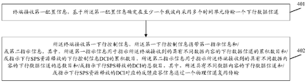
- FIG. 4 is a first schematic flowchart of an information transmission method according to an embodiment of the present application. As shown in FIG. 4, the information transmission method includes the following steps:
- Step 401 The terminal receives the first configuration information, and determines, based on the first configuration information, that a plurality of time units are used to transmit a downlink data channel in at least one carrier.
- the terminal may be any device capable of communicating with a network, such as a mobile phone, a tablet computer, a vehicle-mounted terminal, and a notebook.
- the terminal may communicate with the network through one carrier and multiple carriers. Further, the terminal receives the first configuration information and determines, based on the first configuration information, that multiple time units are used for transmission in at least one carrier. One downlink data channel.
- the network side configures two carriers for the terminal through the first configuration information, namely CC1 and CC2.
- CC1 uses one time unit to transmit a downlink data channel.
- the following data channel is PDSCH as an example.
- CC2 uses three time units to transmit a downlink data channel.
- the following data channel is PDSCH as an example.
- the above example is that one of the two carriers uses multiple time units to transmit a downlink data channel, and is not limited to this.
- the network side can configure both carriers to use multiple time units to transmit one downlink data channel.
- the network side configures one or several carriers to transmit a downlink data channel by using multiple time units, that is, the carrier is configured as a carrier with time slot aggregation, and the terminal uses time slots on the carrier.
- the downlink data channel is transmitted in an aggregated manner.
- Step 402 The terminal receives first downlink control information, and the first downlink control information carries first indication information and / or second indication information, where the first indication information is used to instruct the terminal to receive The cumulative number of downlink data channels with different data content and / or the cumulative number of downlink control information DCI indicating the release of downlink SPS resources, the second indication information is used to indicate that the terminal has different data content received
- the total number of downlink data channels and / or the total number of DCIs released by the downlink SPS, where the downlink data channels with different data content and / or the feedback response information corresponding to the DCIs released by the downlink SPS resources pass through a physical channel Multiplexing transmission.
- the first indication information corresponds to a counter DAI (counter DAI)
- the second indication information corresponds to a total DAI (total DAI)
- the cumulative number indicated by the first indication information is for downlink data channels of different data contents.
- the total number indicated by the second indication information is for the downlink data channels of different data contents and / or the downlink control information DCI released by the SPS resources.
- the first indication information and the first indication information are represented by two bits.
- the first indication information is used to indicate a cumulative number of downlink data channels received by the terminal and carrying different transport blocks TB.
- multiple downlink data channels transmitting the same TB correspond to the same first indication information.
- the second indication information is used to indicate the total number of downlink data channels received by the terminal that carry different TBs.
- the first indication information is used to indicate a cumulative number of downlink data channels corresponding to different HARQ processes received by the terminal.
- multiple downlink data channels corresponding to the same HARQ process correspond to the same first indication information.
- the second indication information is used to indicate a total number of downlink data channels received by the terminal and corresponding to different HARQ processes.
- the downlink data channel is transmitted through a target resource unit, and the target resource unit is determined through carrier information and downlink channel monitoring time information. Further, at least one of carrier information and downlink channel monitoring time information corresponding to different downlink data channels is different.
- the upper row represents each time unit on carrier 1 (CC1), where the number of PDSCHs transmitted repeatedly on CC1 is 1, that is,
- the lower row represents each time unit on carrier 2 (CC2), where the number of repeated PDSCH transmissions on CC2 is 4, that is,
- the terminal needs to feed back 3-bit ACK / NACK information in an uplink (UL) time unit.
- 4 identical PDSCHs repeatedly transmitted on CC2 correspond to 1-bit ACK / NACK information.
- Four identical PDSCH corresponding to 4-bit ACK / NACK information significantly saves uplink control overhead.
- the granularity of the time unit may be a subframe, a time slot, or an sTTI, or another fixed time length.
- the first indication information in the embodiment of the present application may not only be used to indicate the cumulative number of downlink data channels with different data contents received by the terminal, but also may be used to indicate the cumulative number of DCIs released by SPS resources.
- the second indication information in the embodiment of the present application can be used not only to indicate the total number of downlink data channels with different data content received by the terminal, but also to indicate the total number of DCIs released by SPS resources.
- FIG. 6 is a second flowchart of an information transmission method according to an embodiment of the present application. As shown in FIG. 6, the information transmission method includes the following steps:
- Step 601 The network device sends first configuration information, where the first configuration information is used by the terminal to determine that a plurality of time units are used to transmit a downlink data channel in at least one carrier.
- the network device may be a base station, for example, a gNB in 5G, or an eNB in 4G.
- the network device sends the first configuration information to a terminal.
- the terminal may be any device capable of communicating with the network, such as a mobile phone, a tablet computer, a vehicle-mounted terminal, and a notebook.
- the terminal may communicate with the network through one carrier and multiple carriers.
- the network side configures two carriers for the terminal through the first configuration information, namely CC1 and CC2.
- CC1 uses one time unit to transmit a downlink data channel.
- the following data channel is PDSCH as an example.
- CC2 uses three time units to transmit a downlink data channel.
- the following data channel is PDSCH as an example.
- the above example is that one of the two carriers uses multiple time units to transmit a downlink data channel, and is not limited to this.
- the network side can configure both carriers to use multiple time units to transmit one downlink data channel.
- the network side configures one or several carriers to transmit a downlink data channel by using multiple time units, that is, the carrier is configured as a carrier with time slot aggregation, and the terminal uses time slots on the carrier.
- the downlink data channel is transmitted in an aggregated manner.
- Step 602 The network device sends first downlink control information, where the first downlink control information carries first indication information and / or second indication information, wherein the first indication information is used to instruct the terminal.
- the total number of channels and / or the total number of DCIs indicating the release of downlink SPS, wherein the downlink data channels with different data content and / or the feedback response information corresponding to the DCI indicating the release of downlink SPS resources are multiplexed through one physical channel transmission.
- the first indication information corresponds to a counter DAI (counter DAI)
- the second indication information corresponds to a total DAI (total DAI)
- the cumulative number indicated by the first indication information is for downlink data channels of different data contents.
- the total number indicated by the second indication information is for the downlink data channels of different data contents and / or the downlink control information DCI released by the SPS resources.
- the first indication information and the first indication information are represented by two bits.
- the first indication information is used to indicate a cumulative number of downlink data channels received by the terminal and carrying different transport blocks TB.
- multiple downlink data channels transmitting the same TB correspond to the same first indication information.
- the second indication information is used to indicate the total number of downlink data channels received by the terminal that carry different TBs.
- the first indication information is used to indicate a cumulative number of downlink data channels corresponding to different HARQ processes received by the terminal.
- multiple downlink data channels corresponding to the same HARQ process correspond to the same first indication information.
- the second indication information is used to indicate a total number of downlink data channels received by the terminal and corresponding to different HARQ processes.
- the downlink data channel is transmitted through a target resource unit, and the target resource unit is determined by carrier information and downlink channel monitoring time information. Further, at least one of carrier information and downlink channel monitoring time information corresponding to different downlink data channels is different.
- the upper row represents each time unit on carrier 1 (CC1), where the number of PDSCHs transmitted repeatedly on CC1 is 1, that is,
- the lower row represents each time unit on carrier 2 (CC2), where the number of repeated PDSCH transmissions on CC2 is 4, that is,
- the terminal needs to feed back 3-bit ACK / NACK information in an uplink (UL) time unit.
- 4 identical PDSCHs repeatedly transmitted on CC2 correspond to 1-bit ACK / NACK information.
- Four identical PDSCH corresponding to 4-bit ACK / NACK information significantly saves uplink control overhead.
- the granularity of the time unit may be a subframe, a time slot, or an sTTI, or another fixed time length.
- the first indication information in the embodiment of the present application may not only be used to indicate the cumulative number of downlink data channels with different data content received by the terminal, but also may be used to indicate the cumulative number of DCI released by SPS resources.
- the second indication information in the embodiment of the present application can be used not only to indicate the total number of downlink data channels with different data content received by the terminal, but also to indicate the total number of DCIs released by SPS resources.
- FIG. 7 is a first schematic structural diagram of an information transmission device according to an embodiment of the present application. As shown in FIG. 7, the device includes:
- a first receiving unit 701 configured to receive first configuration information, and determine, based on the first configuration information, that multiple time units are used to transmit a downlink data channel in at least one carrier;
- a second receiving unit 702 is configured to receive first downlink control information, where the first downlink control information carries first indication information and / or second indication information, wherein the first indication information is used to instruct the The cumulative number of downlink data channels with different data content received by the terminal and / or the cumulative number of DCI indicating SPS resource release, the second indication information is used to indicate the downlink data received by the terminal with different data content
- the total number of channels and / or the total number of DCIs indicating the release of downlink SPS, wherein the downlink data channels with different data content and / or the feedback response information corresponding to the DCI indicating the release of downlink SPS resources are multiplexed through one physical channel transmission.
- the first indication information is used to indicate a cumulative number of downlink data channels received by the terminal with different data contents, and includes:
- the first indication information is used to indicate a cumulative number of downlink data channels that are received by the terminal and carry different TBs.
- multiple downlink data channels transmitting the same TB correspond to the same first indication information.
- the second indication information is used to indicate the total number of downlink data channels received by the terminal with different data contents, and includes:
- the second indication information is used to indicate a total number of downlink data channels that are received by the terminal and carry different TBs.
- the transmission is the same Multiple downlink data channels of a TB are counted once.
- the first indication information is used to indicate a cumulative number of downlink data channels received by the terminal with different data contents, and includes:
- the first indication information is used to indicate a cumulative number of downlink data channels corresponding to different HARQ processes received by the terminal.
- multiple downlink data channels corresponding to the same HARQ process correspond to the same first Instructions.
- the second indication information is used to indicate the total number of downlink data channels received by the terminal with different data contents, and includes:
- the second indication information is used to indicate the total number of downlink data channels corresponding to different HARQ processes received by the terminal.
- the total number indicated by the second indication information corresponds to the same Multiple downlink data channels of the HARQ process are counted once.
- the downlink data channel is transmitted through a target resource unit, and the target resource unit is determined by carrier information and downlink channel monitoring time information.
- At least one of carrier information and downlink channel monitoring time information corresponding to different downlink data channels is different.
- FIG. 8 is a second schematic diagram of the structure and composition of an information transmission device according to an embodiment of the present application. As shown in FIG. 8, the device includes:
- a first sending unit 801 configured to send first configuration information, where the first configuration information is used by a terminal to determine that multiple time units are used to transmit a downlink data channel in at least one carrier;
- a second sending unit 802 is configured to send first downlink control information, where the first downlink control information carries first indication information and / or second indication information, where the first indication information is used to instruct the The cumulative number of downlink data channels with different data content received by the terminal and / or the cumulative number of DCI indicating the release of downlink SPS resources, the second indication information is used to indicate that the downlink has different data content received by the terminal The total number of data channels and / or the total number of DCIs indicating the release of the downlink SPS, wherein the downlink data channels with different data content and / or the feedback response information corresponding to the DCI indicating the release of the downlink SPS resources are recovered through a physical channel. With transmission.
- the first indication information is used to indicate a cumulative number of downlink data channels received by the terminal with different data contents, and includes:
- the first indication information is used to indicate a cumulative number of downlink data channels that are received by the terminal and carry different TBs.
- multiple downlink data channels transmitting the same TB correspond to the same first indication information.
- the second indication information is used to indicate the total number of downlink data channels received by the terminal with different data contents, and includes:
- the second indication information is used to indicate a total number of downlink data channels that are received by the terminal and carry different TBs.
- the transmission is the same Multiple downlink data channels of a TB are counted once.
- the first indication information is used to indicate a cumulative number of downlink data channels received by the terminal with different data contents, and includes:
- the first indication information is used to indicate a cumulative number of downlink data channels corresponding to different HARQ processes received by the terminal.
- multiple downlink data channels corresponding to the same HARQ process correspond to the same first Instructions.
- the second indication information is used to indicate the total number of downlink data channels received by the terminal with different data contents, and includes:
- the second indication information is used to indicate the total number of downlink data channels corresponding to different HARQ processes received by the terminal.
- the total number indicated by the second indication information corresponds to the same Multiple downlink data channels of the HARQ process are counted once.
- the downlink data channel is transmitted through a target resource unit, and the target resource unit is determined by carrier information and downlink channel monitoring time information.
- At least one of carrier information and downlink channel monitoring time information corresponding to different downlink data channels is different.
- FIG. 9 is a schematic structural diagram of a communication device 600 according to an embodiment of the present application.
- the communication device may be a terminal or a network device.
- the communication device 600 shown in FIG. 9 includes a processor 610, and the processor 610 may call and run a computer program from a memory to implement the method in the embodiment of the present application.
- the communication device 600 may further include a memory 620.
- the processor 610 may call and run a computer program from the memory 620 to implement the method in the embodiment of the present application.
- the memory 620 may be a separate device independent of the processor 610, or may be integrated in the processor 610.
- the communication device 600 may further include a transceiver 630, and the processor 610 may control the transceiver 630 to communicate with other devices, and specifically, may send information or data to other devices, or receive other Information or data sent by the device.
- the transceiver 630 may include a transmitter and a receiver.
- the transceiver 630 may further include antennas, and the number of antennas may be one or more.
- the communication device 600 may specifically be a network device according to the embodiment of the present application, and the communication device 600 may implement a corresponding process implemented by the network device in each method of the embodiment of the present application. For brevity, details are not described herein again. .
- the communication device 600 may specifically be a mobile terminal / terminal of the embodiment of the present application, and the communication device 600 may implement the corresponding process implemented by the mobile terminal / terminal in each method of the embodiment of the present application. For simplicity, in This will not be repeated here.
- FIG. 10 is a schematic structural diagram of a chip according to an embodiment of the present application.
- the chip 700 shown in FIG. 10 includes a processor 710, and the processor 710 can call and run a computer program from a memory to implement the method in the embodiment of the present application.
- the chip 700 may further include a memory 720.
- the processor 710 may call and run a computer program from the memory 720 to implement the method in the embodiment of the present application.
- the memory 720 may be a separate device independent of the processor 710, or may be integrated in the processor 710.
- the chip 700 may further include an input interface 730.
- the processor 710 may control the input interface 730 to communicate with other devices or chips. Specifically, the processor 710 may obtain information or data sent by the other devices or chips.
- the chip 700 may further include an output interface 740.
- the processor 710 may control the output interface 740 to communicate with other devices or chips. Specifically, the processor 710 may output information or data to the other devices or chips.
- the chip may be applied to the network device in the embodiment of the present application, and the chip may implement the corresponding process implemented by the network device in each method of the embodiment of the present application.
- the chip may be applied to the network device in the embodiment of the present application, and the chip may implement the corresponding process implemented by the network device in each method of the embodiment of the present application.
- the chip can be applied to the mobile terminal / terminal in the embodiments of the present application, and the chip can implement the corresponding process implemented by the mobile terminal / terminal in each method of the embodiments of the present application. To repeat.
- the chip mentioned in the embodiments of the present application may also be referred to as a system-level chip, a system chip, a chip system or a system-on-chip.
- FIG. 11 is a schematic block diagram of a communication system 900 according to an embodiment of the present application. As shown in FIG. 11, the communication system 900 includes a terminal 910 and a network device 920.
- the terminal 910 may be used to implement the corresponding functions implemented by the terminal in the foregoing method
- the network device 920 may be used to implement the corresponding functions implemented by the network device in the foregoing method.
- details are not described herein again.
- the processor in the embodiment of the present application may be an integrated circuit chip and has a signal processing capability.
- each step of the foregoing method embodiment may be completed by using an integrated logic circuit of hardware in a processor or an instruction in a form of software.
- the above processor may be a general-purpose processor, a digital signal processor (DSP), an application specific integrated circuit (ASIC), an off-the-shelf programmable gate array (Field, Programmable Gate Array, FPGA), or other Programming logic devices, discrete gate or transistor logic devices, discrete hardware components.
- DSP digital signal processor
- ASIC application specific integrated circuit
- FPGA off-the-shelf programmable gate array
- Various methods, steps, and logical block diagrams disclosed in the embodiments of the present application can be implemented or executed.
- a general-purpose processor may be a microprocessor or the processor may be any conventional processor or the like.
- the steps of the method disclosed in combination with the embodiments of the present application may be directly implemented by a hardware decoding processor, or may be performed by using a combination of hardware and software modules in the decoding processor.
- the software module may be located in a mature storage medium such as a random access memory, a flash memory, a read-only memory, a programmable read-only memory, or an electrically erasable programmable memory, a register, and the like.
- the storage medium is located in a memory, and the processor reads the information in the memory and completes the steps of the foregoing method in combination with its hardware.
- the memory in the embodiment of the present application may be a volatile memory or a non-volatile memory, or may include both volatile and non-volatile memory.
- the non-volatile memory may be a read-only memory (ROM), a programmable read-only memory (PROM), an erasable programmable read-only memory (EPROM), and an electronic memory. Erase programmable read-only memory (EPROM, EEPROM) or flash memory.
- the volatile memory may be Random Access Memory (RAM), which is used as an external cache.
- RAM Static Random Access Memory
- DRAM Dynamic Random Access Memory
- Synchronous Dynamic Random Access Memory Synchronous Dynamic Random Access Memory
- SDRAM double data rate synchronous dynamic random access memory
- Double SDRAM, DDR SDRAM enhanced synchronous dynamic random access memory
- Enhanced SDRAM, ESDRAM synchronous connection dynamic random access memory
- Synchronous DRAM Synchronous Dynamic Random Access Memory
- Enhanced SDRAM Enhanced SDRAM, ESDRAM
- synchronous connection dynamic random access memory Synchrobus RAM, SLDRAM
- Direct Rambus RAM Direct Rambus RAM
- the memory in the embodiment of the present application may also be a static random access memory (static RAM, SRAM), a dynamic random access memory (dynamic RAM, DRAM), Synchronous dynamic random access memory (SDRAM), double data rate synchronous dynamic random access memory (Double SDRAM, DDR SDRAM), enhanced synchronous dynamic random access memory (enhanced SDRAM, ESDRAM), synchronous connection Dynamic random access memory (synch link DRAM, SLDRAM) and direct memory bus random access memory (Direct RAMbus RAM, DR RAM) and so on. That is, the memories in the embodiments of the present application are intended to include, but not limited to, these and any other suitable types of memories.
- An embodiment of the present application further provides a computer-readable storage medium for storing a computer program.
- the computer-readable storage medium may be applied to the network device in the embodiment of the present application, and the computer program causes the computer to execute the corresponding process implemented by the network device in each method in the embodiment of the present application. For simplicity, here No longer.
- the computer-readable storage medium may be applied to a mobile terminal / terminal in the embodiments of the present application, and the computer program causes a computer to execute a corresponding process implemented by the mobile terminal / terminal in each method of the embodiments of the present application in order to Concise, I won't repeat them here.
- An embodiment of the present application further provides a computer program product, including computer program instructions.
- the computer program product can be applied to the network device in the embodiment of the present application, and the computer program instruction causes the computer to execute a corresponding process implemented by the network device in each method in the embodiment of the present application. More details.
- the computer program product can be applied to a mobile terminal / terminal in the embodiments of the present application, and the computer program instructions cause the computer to execute a corresponding process implemented by the mobile terminal / terminal in each method of the embodiments of the present application for the sake of brevity , Will not repeat them here.
- the embodiment of the present application also provides a computer program.
- the computer program may be applied to a network device in the embodiment of the present application.
- the computer program When the computer program is run on a computer, the computer is caused to execute a corresponding process implemented by the network device in each method in the embodiment of the present application. , Will not repeat them here.
- the computer program may be applied to a mobile terminal / terminal in the embodiment of the present application, and when the computer program is run on a computer, the computer is caused to execute the corresponding method implemented by the mobile terminal / terminal in each method of the embodiment of the present application For the sake of brevity, we will not repeat them here.
- the disclosed systems, devices, and methods may be implemented in other ways.
- the device embodiments described above are only schematic.
- the division of the unit is only a logical function division.
- multiple units or components may be combined or Can be integrated into another system, or some features can be ignored or not implemented.
- the displayed or discussed mutual coupling or direct coupling or communication connection may be indirect coupling or communication connection through some interfaces, devices or units, which may be electrical, mechanical or other forms.
- the units described as separate components may or may not be physically separated, and the components displayed as units may or may not be physical units, may be located in one place, or may be distributed on multiple network units. Some or all of the units may be selected according to actual needs to achieve the objective of the solution of this embodiment.
- each functional unit in each embodiment of the present application may be integrated into one processing unit, or each of the units may exist separately physically, or two or more units may be integrated into one unit.
- the functions are implemented in the form of software functional units and sold or used as independent products, they can be stored in a computer-readable storage medium.
- the technical solution of this application is essentially a part that contributes to the existing technology or a part of the technical solution can be embodied in the form of a software product.
- the computer software product is stored in a storage medium, including Several instructions are used to cause a computer device (which may be a personal computer, a server, or a network device, etc.) to perform all or part of the steps of the method described in the embodiments of the present application.
- the aforementioned storage media include: U disk, mobile hard disk, read-only memory (Read-Only Memory) ROM, random access memory (Random Access Memory, RAM), magnetic disks or optical disks and other media that can store program codes .
Landscapes
- Engineering & Computer Science (AREA)
- Signal Processing (AREA)
- Computer Networks & Wireless Communication (AREA)
- Mobile Radio Communication Systems (AREA)
Abstract
La présente invention concerne, selon des modes de réalisation, un procédé et un dispositif de transmission d'informations et un terminal. Le procédé de transmission d'informations comprend les étapes suivantes : un terminal reçoit des premières informations de configuration, et détermine, sur la base des premières informations de configuration, que de multiples unités de temps doivent être utilisées pour transmettre un canal de données de liaison descendante sur au moins une porteuse; et le terminal reçoit des premières informations de commande de liaison descendante, les premières informations de commande de liaison descendante transportant des premières informations d'indication et/ou des secondes informations d'indication, les premières informations d'indication indiquant un nombre cumulé de canaux de données de liaison descendante ayant différents contenus de données reçus par le terminal et/ou indiquant un nombre cumulé de DCI utilisées pour libérer des ressources SPS de liaison descendante, et les secondes informations d'indication indiquant un nombre total de canaux de données de liaison descendante ayant différents contenus de données reçus par le terminal et/ou indiquant un nombre total de DCI utilisées pour libérer des ressources SPS de liaison descendante.
Priority Applications (4)
| Application Number | Priority Date | Filing Date | Title |
|---|---|---|---|
| CN201880002981.XA CN109565839B (zh) | 2018-09-19 | 2018-09-19 | 一种信息传输方法及装置、终端 |
| PCT/CN2018/106520 WO2020056632A1 (fr) | 2018-09-19 | 2018-09-19 | Procédé et dispositif de transmission d'informations, et terminal |
| EP18918413.8A EP3648391B1 (fr) | 2018-09-19 | 2018-09-19 | Procédé et dispositif de transmission d'informations |
| US16/738,918 US20200145973A1 (en) | 2018-09-19 | 2020-01-09 | Information transmission method, apparatus and terminal |
Applications Claiming Priority (1)
| Application Number | Priority Date | Filing Date | Title |
|---|---|---|---|
| PCT/CN2018/106520 WO2020056632A1 (fr) | 2018-09-19 | 2018-09-19 | Procédé et dispositif de transmission d'informations, et terminal |
Related Child Applications (1)
| Application Number | Title | Priority Date | Filing Date |
|---|---|---|---|
| US16/738,918 Continuation US20200145973A1 (en) | 2018-09-19 | 2020-01-09 | Information transmission method, apparatus and terminal |
Publications (1)
| Publication Number | Publication Date |
|---|---|
| WO2020056632A1 true WO2020056632A1 (fr) | 2020-03-26 |
Family
ID=65872723
Family Applications (1)
| Application Number | Title | Priority Date | Filing Date |
|---|---|---|---|
| PCT/CN2018/106520 Ceased WO2020056632A1 (fr) | 2018-09-19 | 2018-09-19 | Procédé et dispositif de transmission d'informations, et terminal |
Country Status (4)
| Country | Link |
|---|---|
| US (1) | US20200145973A1 (fr) |
| EP (1) | EP3648391B1 (fr) |
| CN (1) | CN109565839B (fr) |
| WO (1) | WO2020056632A1 (fr) |
Cited By (1)
| Publication number | Priority date | Publication date | Assignee | Title |
|---|---|---|---|---|
| CN114080040A (zh) * | 2020-08-20 | 2022-02-22 | 大唐移动通信设备有限公司 | 一种下行信道传输方法及装置 |
Families Citing this family (7)
| Publication number | Priority date | Publication date | Assignee | Title |
|---|---|---|---|---|
| EP3958627B1 (fr) | 2019-07-05 | 2024-03-13 | Guangdong Oppo Mobile Telecommunications Corp., Ltd. | Procédé et dispositif de transmission de signaux de liaison descendante |
| CN112787773A (zh) * | 2019-11-08 | 2021-05-11 | 索尼公司 | 电子设备、通信方法和存储介质 |
| WO2021092955A1 (fr) * | 2019-11-15 | 2021-05-20 | Oppo广东移动通信有限公司 | Procédé de réception de signalisation de commande de liaison descendante, dispositif de réseau et dispositif terminal |
| EP4132180B1 (fr) * | 2020-04-10 | 2024-12-11 | Guangdong Oppo Mobile Telecommunications Corp., Ltd. | Procédé et dispositif de configuration de dai, procédé et dispositif d'indication de dai, procédé et dispositif d'envoi de dai, et support |
| CN114070498B (zh) * | 2020-07-31 | 2023-03-14 | 展讯通信(上海)有限公司 | 下行分配指示的确定方法及装置、下行分配指示的配置方法及装置、存储介质、终端、基站 |
| CN115918011B (zh) * | 2020-08-26 | 2024-10-22 | 华为技术有限公司 | 生成混合自动重复请求harq码本的方法和装置 |
| WO2022073202A1 (fr) * | 2020-10-09 | 2022-04-14 | Apple Inc. | Amélioration de la couverture et rendement du système par un ue |
Citations (5)
| Publication number | Priority date | Publication date | Assignee | Title |
|---|---|---|---|---|
| CN102263620A (zh) * | 2010-05-28 | 2011-11-30 | 华为技术有限公司 | 一种对多载波应答信息的反馈方法、装置和系统 |
| US20170134140A1 (en) * | 2015-11-06 | 2017-05-11 | Innovative Technology Lab Co., Ltd. | Apparatus and method for performing hybrid automatic repeat request operation in wireless communication system supporting carrier aggregation |
| CN107409016A (zh) * | 2015-04-06 | 2017-11-28 | 三星电子株式会社 | 针对确认信息的码字确定 |
| CN107852718A (zh) * | 2015-07-15 | 2018-03-27 | 株式会社Ntt都科摩 | 用户终端、无线基站以及无线通信方法 |
| CN108270539A (zh) * | 2017-01-03 | 2018-07-10 | 北京三星通信技术研究有限公司 | 数据传输的方法及设备 |
-
2018
- 2018-09-19 WO PCT/CN2018/106520 patent/WO2020056632A1/fr not_active Ceased
- 2018-09-19 CN CN201880002981.XA patent/CN109565839B/zh active Active
- 2018-09-19 EP EP18918413.8A patent/EP3648391B1/fr active Active
-
2020
- 2020-01-09 US US16/738,918 patent/US20200145973A1/en not_active Abandoned
Patent Citations (5)
| Publication number | Priority date | Publication date | Assignee | Title |
|---|---|---|---|---|
| CN102263620A (zh) * | 2010-05-28 | 2011-11-30 | 华为技术有限公司 | 一种对多载波应答信息的反馈方法、装置和系统 |
| CN107409016A (zh) * | 2015-04-06 | 2017-11-28 | 三星电子株式会社 | 针对确认信息的码字确定 |
| CN107852718A (zh) * | 2015-07-15 | 2018-03-27 | 株式会社Ntt都科摩 | 用户终端、无线基站以及无线通信方法 |
| US20170134140A1 (en) * | 2015-11-06 | 2017-05-11 | Innovative Technology Lab Co., Ltd. | Apparatus and method for performing hybrid automatic repeat request operation in wireless communication system supporting carrier aggregation |
| CN108270539A (zh) * | 2017-01-03 | 2018-07-10 | 北京三星通信技术研究有限公司 | 数据传输的方法及设备 |
Non-Patent Citations (1)
| Title |
|---|
| See also references of EP3648391A4 * |
Cited By (1)
| Publication number | Priority date | Publication date | Assignee | Title |
|---|---|---|---|---|
| CN114080040A (zh) * | 2020-08-20 | 2022-02-22 | 大唐移动通信设备有限公司 | 一种下行信道传输方法及装置 |
Also Published As
| Publication number | Publication date |
|---|---|
| EP3648391B1 (fr) | 2021-08-04 |
| EP3648391A1 (fr) | 2020-05-06 |
| CN109565839A (zh) | 2019-04-02 |
| CN109565839B (zh) | 2021-05-04 |
| US20200145973A1 (en) | 2020-05-07 |
| EP3648391A4 (fr) | 2020-07-22 |
Similar Documents
| Publication | Publication Date | Title |
|---|---|---|
| CN109565839B (zh) | 一种信息传输方法及装置、终端 | |
| TWI829760B (zh) | 用於側行鏈路的通信方法和設備 | |
| US11991729B2 (en) | Resource configuration method and apparatus, and communication device | |
| WO2020143050A1 (fr) | Procédé de détermination d'informations de commande de liaison descendante (dci) pour planification inter-porteuses, dispositif terminal et dispositif de réseau | |
| US12113624B2 (en) | Feedback information transmission method and apparatus and communications device | |
| CN113517973B (zh) | 无线通信方法、终端设备和网络设备 | |
| WO2020062318A1 (fr) | Procédé de communication sans fil et dispositif terminal | |
| WO2021088260A1 (fr) | Procédé de transmission d'informations de rétroaction, équipement terminal et dispositif de réseau | |
| US11825479B2 (en) | Method for determining uplink control information and communications device | |
| WO2020143052A1 (fr) | Procédé permettant de transmettre des informations de rétroaction, dispositif terminal et dispositif de réseau | |
| JP2022508479A (ja) | フィードバックリソースの多重化方法、端末装置及びネットワーク装置 | |
| US11849436B2 (en) | Radio communication method and device | |
| US12426054B2 (en) | Channel processing method and electronic device | |
| WO2020037655A1 (fr) | Procédé et dispositif pour déterminer une longueur d'informations de rétroaction, et appareil de communication | |
| WO2020061773A1 (fr) | Procédé d'attribution de ressources de rétroaction, dispositif terminal et dispositif de réseau | |
| WO2020061916A1 (fr) | Procédé et appareil de détermination d'état de déclencheur, terminal, et dispositif de réseau | |
| WO2020042036A1 (fr) | Procédé de communication sans fil et dispositif de communication | |
| WO2021000239A1 (fr) | Procédé de communication sans fil, dispositif de réseau et dispositif terminal | |
| WO2020056719A1 (fr) | Procédé de détermination de temps de transmission d'informations, dispositif terminal et dispositif de réseau | |
| CN114374481B (zh) | 一种反馈时序的确定方法、终端设备及网络设备 | |
| CN116998122A (zh) | 一种信息传输方法、电子设备及存储介质 | |
| WO2020056556A1 (fr) | Procédé de communication pour un spectre de fréquence non autorisé, et équipement terminal et dispositif de réseau | |
| WO2021142636A1 (fr) | Procédé de transmission de liaison montante et dispositif terminal |
Legal Events
| Date | Code | Title | Description |
|---|---|---|---|
| ENP | Entry into the national phase |
Ref document number: 2018918413 Country of ref document: EP Effective date: 20191122 |
|
| NENP | Non-entry into the national phase |
Ref country code: DE |