WO2020059094A1 - 作業機械 - Google Patents
作業機械 Download PDFInfo
- Publication number
- WO2020059094A1 WO2020059094A1 PCT/JP2018/034896 JP2018034896W WO2020059094A1 WO 2020059094 A1 WO2020059094 A1 WO 2020059094A1 JP 2018034896 W JP2018034896 W JP 2018034896W WO 2020059094 A1 WO2020059094 A1 WO 2020059094A1
- Authority
- WO
- WIPO (PCT)
- Prior art keywords
- speed
- target
- point
- work
- candidate
- Prior art date
- Legal status (The legal status is an assumption and is not a legal conclusion. Google has not performed a legal analysis and makes no representation as to the accuracy of the status listed.)
- Ceased
Links
Images







Classifications
-
- E—FIXED CONSTRUCTIONS
- E02—HYDRAULIC ENGINEERING; FOUNDATIONS; SOIL SHIFTING
- E02F—DREDGING; SOIL-SHIFTING
- E02F3/00—Dredgers; Soil-shifting machines
- E02F3/04—Dredgers; Soil-shifting machines mechanically-driven
- E02F3/28—Dredgers; Soil-shifting machines mechanically-driven with digging tools mounted on a dipper- or bucket-arm, i.e. there is either one arm or a pair of arms, e.g. dippers, buckets
- E02F3/36—Component parts
- E02F3/42—Drives for dippers, buckets, dipper-arms or bucket-arms
- E02F3/43—Control of dipper or bucket position; Control of sequence of drive operations
- E02F3/431—Control of dipper or bucket position; Control of sequence of drive operations for bucket-arms, front-end loaders, dumpers or the like
-
- E—FIXED CONSTRUCTIONS
- E02—HYDRAULIC ENGINEERING; FOUNDATIONS; SOIL SHIFTING
- E02F—DREDGING; SOIL-SHIFTING
- E02F9/00—Component parts of dredgers or soil-shifting machines, not restricted to one of the kinds covered by groups E02F3/00 - E02F7/00
- E02F9/20—Drives; Control devices
- E02F9/22—Hydraulic or pneumatic drives
- E02F9/2221—Control of flow rate; Load sensing arrangements
-
- E—FIXED CONSTRUCTIONS
- E02—HYDRAULIC ENGINEERING; FOUNDATIONS; SOIL SHIFTING
- E02F—DREDGING; SOIL-SHIFTING
- E02F3/00—Dredgers; Soil-shifting machines
- E02F3/04—Dredgers; Soil-shifting machines mechanically-driven
- E02F3/28—Dredgers; Soil-shifting machines mechanically-driven with digging tools mounted on a dipper- or bucket-arm, i.e. there is either one arm or a pair of arms, e.g. dippers, buckets
- E02F3/36—Component parts
- E02F3/42—Drives for dippers, buckets, dipper-arms or bucket-arms
- E02F3/43—Control of dipper or bucket position; Control of sequence of drive operations
- E02F3/435—Control of dipper or bucket position; Control of sequence of drive operations for dipper-arms, backhoes or the like
- E02F3/437—Control of dipper or bucket position; Control of sequence of drive operations for dipper-arms, backhoes or the like providing automatic sequences of movements, e.g. linear excavation, keeping dipper angle constant
-
- E—FIXED CONSTRUCTIONS
- E02—HYDRAULIC ENGINEERING; FOUNDATIONS; SOIL SHIFTING
- E02F—DREDGING; SOIL-SHIFTING
- E02F3/00—Dredgers; Soil-shifting machines
- E02F3/04—Dredgers; Soil-shifting machines mechanically-driven
- E02F3/28—Dredgers; Soil-shifting machines mechanically-driven with digging tools mounted on a dipper- or bucket-arm, i.e. there is either one arm or a pair of arms, e.g. dippers, buckets
- E02F3/36—Component parts
- E02F3/42—Drives for dippers, buckets, dipper-arms or bucket-arms
- E02F3/43—Control of dipper or bucket position; Control of sequence of drive operations
- E02F3/435—Control of dipper or bucket position; Control of sequence of drive operations for dipper-arms, backhoes or the like
-
- E—FIXED CONSTRUCTIONS
- E02—HYDRAULIC ENGINEERING; FOUNDATIONS; SOIL SHIFTING
- E02F—DREDGING; SOIL-SHIFTING
- E02F9/00—Component parts of dredgers or soil-shifting machines, not restricted to one of the kinds covered by groups E02F3/00 - E02F7/00
- E02F9/20—Drives; Control devices
- E02F9/22—Hydraulic or pneumatic drives
- E02F9/2221—Control of flow rate; Load sensing arrangements
- E02F9/2225—Control of flow rate; Load sensing arrangements using pressure-compensating valves
- E02F9/2228—Control of flow rate; Load sensing arrangements using pressure-compensating valves including an electronic controller
-
- E—FIXED CONSTRUCTIONS
- E02—HYDRAULIC ENGINEERING; FOUNDATIONS; SOIL SHIFTING
- E02F—DREDGING; SOIL-SHIFTING
- E02F9/00—Component parts of dredgers or soil-shifting machines, not restricted to one of the kinds covered by groups E02F3/00 - E02F7/00
- E02F9/20—Drives; Control devices
- E02F9/22—Hydraulic or pneumatic drives
- E02F9/2264—Arrangements or adaptations of elements for hydraulic drives
- E02F9/2267—Valves or distributors
-
- E—FIXED CONSTRUCTIONS
- E02—HYDRAULIC ENGINEERING; FOUNDATIONS; SOIL SHIFTING
- E02F—DREDGING; SOIL-SHIFTING
- E02F9/00—Component parts of dredgers or soil-shifting machines, not restricted to one of the kinds covered by groups E02F3/00 - E02F7/00
- E02F9/20—Drives; Control devices
- E02F9/22—Hydraulic or pneumatic drives
- E02F9/2264—Arrangements or adaptations of elements for hydraulic drives
- E02F9/2271—Actuators and supports therefor and protection therefor
-
- E—FIXED CONSTRUCTIONS
- E02—HYDRAULIC ENGINEERING; FOUNDATIONS; SOIL SHIFTING
- E02F—DREDGING; SOIL-SHIFTING
- E02F9/00—Component parts of dredgers or soil-shifting machines, not restricted to one of the kinds covered by groups E02F3/00 - E02F7/00
- E02F9/20—Drives; Control devices
- E02F9/22—Hydraulic or pneumatic drives
- E02F9/2278—Hydraulic circuits
-
- E—FIXED CONSTRUCTIONS
- E02—HYDRAULIC ENGINEERING; FOUNDATIONS; SOIL SHIFTING
- E02F—DREDGING; SOIL-SHIFTING
- E02F9/00—Component parts of dredgers or soil-shifting machines, not restricted to one of the kinds covered by groups E02F3/00 - E02F7/00
- E02F9/26—Indicating devices
- E02F9/261—Surveying the work-site to be treated
- E02F9/262—Surveying the work-site to be treated with follow-up actions to control the work tool, e.g. controller
-
- E—FIXED CONSTRUCTIONS
- E02—HYDRAULIC ENGINEERING; FOUNDATIONS; SOIL SHIFTING
- E02F—DREDGING; SOIL-SHIFTING
- E02F9/00—Component parts of dredgers or soil-shifting machines, not restricted to one of the kinds covered by groups E02F3/00 - E02F7/00
- E02F9/26—Indicating devices
- E02F9/264—Sensors and their calibration for indicating the position of the work tool
-
- E—FIXED CONSTRUCTIONS
- E02—HYDRAULIC ENGINEERING; FOUNDATIONS; SOIL SHIFTING
- E02F—DREDGING; SOIL-SHIFTING
- E02F9/00—Component parts of dredgers or soil-shifting machines, not restricted to one of the kinds covered by groups E02F3/00 - E02F7/00
- E02F9/26—Indicating devices
- E02F9/264—Sensors and their calibration for indicating the position of the work tool
- E02F9/265—Sensors and their calibration for indicating the position of the work tool with follow-up actions (e.g. control signals sent to actuate the work tool)
Definitions
- the present invention relates to a working machine such as a hydraulic shovel.
- Patent Document 1 discloses this type of technology.
- the tip of the bucket is defined as a first monitoring point
- the outermost point on the back of the bucket is defined as a second monitoring point
- a work device working machine
- the boom cylinder speed (first adjustment speed) at this time is S1
- the boom cylinder speed (second adjustment speed) at the time of controlling the working device so that the second monitoring point does not enter the target surface is S2.
- the working device is controlled according to the larger one of S1 and S2. That is, if S1> S2, the working device is controlled so as to prevent the first monitoring point from entering the target surface. On the other hand, if S2> S1, the working device is controlled so as to prevent the second monitoring point from entering the target surface.
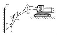
- a work point serving as a reference for performing control for preventing intrusion into the target surface 60
- a work point specifically, a bucket tip 8a and a back end 8b.
- the bucket tip 8a and the back end 8b are at the same distance from the target surface 60 (that is, the bucket bottom connecting the bucket tip 8a and the back end 8b is the target surface 60).
- parallel the bucket bottom connecting the bucket tip 8a and the back end 8b is the target surface 60.
- the speed of the bucket tip 8a is defined to be negative above the target surface 60 and closer to the target surface 60, and positive when moving away from the target surface 60.
- the cylinder speed is defined as positive in the direction of extension and negative in the direction of contraction.
- the tip 8a and the back end 8b of the bucket are located in front and back of a virtual plane 61 including the rotation axis of the arm and perpendicular to the target plane 60.
- the target at the speed (speed vector (Va1, Vb1, Vtgt, Vmoda, Vmodb)) generated at the bucket tip 8a or the back end 8b by the operation of the arm and the boom. Attention is paid only to a component perpendicular to the surface 60. That is, although a component parallel to the target plane 60 is actually generated, the description will be omitted.
- the target operation speed of the bucket tip 8a (however, only the vertical component) is Vtgt, which is determined by the distance between the bucket tip 8a and the target surface 60.
- Vtgt The target operation speed of the bucket tip 8a (however, only the vertical component) is Vtgt, which is determined by the distance between the bucket tip 8a and the target surface 60.
- Vmoda Vtgt-Va1
- the boom cylinder speed at which Vmoda occurs at the tip of the bucket is Cbm1
- the direction of the cylinder speed Cbm1 is a contracting direction (that is, a negative direction).
- the control system described in Patent Document 1 in which the two cylinder speeds are compared and the control is performed based on the larger one, in the case of Cbm2, that is, the target surface 60
- the work equipment is controlled to prevent intrusion into the workplace. Since Va1 is positive and Vb1 is negative, it is the bucket rear end 8b that may enter the target surface 60. That is, the control system described in Patent Literature 1 enables semi-automatic excavation molding while preventing the bucket tip and back end from entering the target surface.
- the bucket tip 8a is controlled by the above-described cylinder speed comparison section. It is selected as a target and cannot be properly semi-automatically excavated and formed (that is, the bucket back end 8b enters the target surface 60). If the sign is not defined, the sign of Cbm1 and the sign of Cbm2 are different from each other, and the judgment is impossible if the magnitudes are the same.
- the operation of the arm is the same as that of the bucket tip 8a, and operates clockwise at the angular velocity Wa.
- a speed Vb1 is generated in the negative direction at the bucket rear end 8b by the operator's operation.
- the operation target speed of the bucket back end 8b is also Vtgt because the distance between the bucket tip 8a and the back end 8b from the target surface 60 is the same.
- Vmodb Vtgt-Vb1
- the present invention has been made in view of the above problems, and has as its object to provide a working machine capable of performing semi-automatic excavation forming not only with a target surface (for example, a horizontal surface) at a position where a working point is separated by raising a boom.
- An object of the present invention is to provide a working machine that can prevent a plurality of points on a working device from entering a target surface even when the working point is separated from the target point by boom lowering.
- the present invention provides a working device, a hydraulic cylinder driven by hydraulic oil discharged from a hydraulic pump to operate the working device, and instructs the operation of the hydraulic cylinder in accordance with an operation of an operator.
- each of the plurality of work point candidates When each of the plurality of work point candidates is moved at a corresponding target speed among the plurality of target speeds, The speeds occurring in the candidates are calculated, and the speeds occurring in the remaining work point candidates are grouped for each of the plurality of work point candidates to form a plurality of speed groups, and the plurality of work point candidates are selected from among the plurality of speed groups.
- the hydraulic cylinder is controlled according to the target speed of the work point candidate related to the selected speed group among the plurality of target speeds.
- the present invention it is possible to prevent a plurality of points on the working device from invading the target surface even on the target surface at a position where the work point is separated by the boom lowering.
- FIG. 2 is a configuration diagram illustrating a control system mounted on the work machine illustrated in FIG. 1.
- FIG. 3 is a block diagram illustrating a detailed configuration of the information processing apparatus illustrated in FIG. 2.
- FIG. 5 is a diagram illustrating setting of a work point candidate according to the first embodiment of the present invention.
- FIG. 4 is a block diagram illustrating a detailed configuration of a candidate point speed calculation unit illustrated in FIG. 3.
- FIG. 4 is a block diagram illustrating a detailed configuration of a work point selection unit illustrated in FIG. 3.
- 6 is a truth table showing a relationship between input values of a candidate point speed comparison unit and an output associated therewith according to the first embodiment of the present invention.
- FIG. 1 is a configuration diagram illustrating a control system mounted on the work machine illustrated in FIG. 1.
- FIG. 3 is a block diagram illustrating a detailed configuration of the information processing apparatus illustrated in FIG. 2.
- FIG. 5 is a diagram illustrating setting of a work point candidate according to the first embodiment of the present invention.
- FIG. 4 is a diagram illustrating velocity vectors at the time of vertical surface excavation according to the first embodiment of the present invention.
- 4 is a flowchart illustrating a control flow according to the first embodiment of the present invention. It is a figure showing an example of operation at the time of horizontal plane excavation of a work machine. It is a figure showing an example of operation at the time of vertical excavation of a work machine.
- FIG. 3 is a diagram illustrating a velocity vector at the time of vertical excavation of a work machine. It is a figure showing setting of a work point candidate in a 2nd embodiment of the present invention. It is a truth table which showed the relationship of the input value of the candidate point speed comparison part in 2nd Embodiment of this invention, and the output accompanying it.
- FIG. 3 is a diagram illustrating velocity vectors at the time of vertical surface excavation according to the first embodiment of the present invention. 4 is a flowchart illustrating a control flow according to the first embodiment of the present invention. It is a figure showing an example of operation at
- FIG. 11 is a flowchart illustrating a control flow according to the second embodiment of the present invention.
- FIG. 11 is a block diagram illustrating a detailed configuration of a candidate point speed calculation unit according to a second embodiment of the present invention. It is a block diagram showing the detailed composition of the work point selection part in a 2nd embodiment of the present invention. It is a figure showing a speed vector at the time of horizontal plane excavation of a work machine.
- FIG. 9 is a diagram defining a relationship between a deviation distance D between a target plane and a work point candidate and a target value Vtgt of a component of a speed vector of the work point candidate which is perpendicular to the target plane.
- FIG. 9 is an explanatory diagram in a case where a trajectory of a bucket tip caused by an arm operation is corrected by a boom operation.
- FIG. 1 is a perspective view showing a hydraulic shovel according to a first embodiment of the present invention.
- a hydraulic excavator according to the present embodiment includes a lower traveling body 9 and an upper revolving body 10 which are body bodies, and a multi-joint type working device (front work) mounted in front of the upper revolving body 10.
- Device 15 The multi-joint type working device (front work) mounted in front of the upper revolving body 10.
- the lower traveling body 9 has crawler traveling devices on the left and right, and is driven by left and right traveling hydraulic motors 3b and 3a (only the left 3b is shown).
- the upper swing body 10 is mounted on the lower traveling body 9 so as to be swingable left and right, and is swingably driven by the swing hydraulic motor 4.
- the revolving superstructure 10 is equipped with an engine 14 as a prime mover, a hydraulic pump 2 driven by the engine 14, a control valve 20, and a controller 500 (see FIG. 2) which controls various controls of the hydraulic excavator.
- the working device 15 is swingably attached to the front of the upper swing body 10.
- the working device 15 has a multi-joint structure having a plurality of swingable front members boom 11, arm 12, and bucket 8.
- the boom 11 swings with respect to the upper revolving unit 10 by the extension and contraction of the boom cylinder 5
- the arm 12 swings with respect to the boom 11 by the extension and contraction of the arm cylinder 6, and the bucket 8 moves to the arm 12 by the extension and contraction of the bucket cylinder 7. Swings against.
- FIG. 4 is a perspective view of the bucket 8 in the present embodiment.
- the bucket tip 8a and the bucket back end 8b are adopted as work point candidates set in the work device 15.
- the bucket tip 8a may be any point that projects the bucket tip edge onto a plane perpendicular to the pivot axis of the bucket 8, the arm 12, and the boom 11, and the bucket back edge 8b has the bucket rear edge perpendicular to the bucket pivot axis. Any point can be used as long as the point is projected on a simple plane.
- the bucket edge is a point projected on a plane perpendicular to the bucket rotation axis and passing through the center of the bucket width.
- a hydraulic excavator is provided near a connection between the upper revolving unit 10 and the boom 11;
- attitude sensors 13a to 13d for example, an IMU (Inertial ⁇ Measurement ⁇ Unit: inertial measurement device) can be used.
- the first attitude sensor 13a to the third attitude sensor 13c may be sensors for detecting a relative angle.
- attitude sensors 13a to 13d The angles detected by the attitude sensors 13a to 13d are input to the information processing unit 100 of the controller 500 as attitude signals.
- the upper swing body 10 is provided with a driver's cab, and in the driver's cab, a right operating lever device 1a for driving, which is operated by an operator and outputs an operation signal (electric signal) to the controller 500, Operating devices such as an operating lever device 1b, a right operating lever device 1c, and a left operating lever device 1d are arranged.
- the right operating lever device for traveling 1a issues an operation instruction for the right traveling hydraulic motor 3a
- the left operating lever device for traveling 1b issues an operation instruction for the left traveling hydraulic motor 3b
- the right operating lever device 1c operates with the boom cylinder 5 (boom 11).
- the operation instruction of the bucket cylinder 7 (bucket 8) and the left operation lever device 1d are used to instruct the operation of the arm cylinder 6 (arm 12) and the swing hydraulic motor 4 (upper swing body 10).
- the operation devices 1a to 1d according to the present embodiment are electric levers, and generate an electric signal (operation signal) according to the operation amount and output the generated electric signal to the controller 500.
- the operating devices 1a to 1d may be of a hydraulic pilot type, and the operation amount may be detected by a pressure sensor and input to the controller 500.
- the control valve 20 controls the pressure oil supplied from the hydraulic pump 2 to the hydraulic actuators such as the swing hydraulic motor 4, the boom cylinder 5, the arm cylinder 6, the bucket cylinder 7, and the left and right traveling hydraulic motors 3b and 3a.
- a valve device including a plurality of spools for controlling flow (flow rate and direction).
- the control valve 20 is driven by a drive signal (control valve drive signal) output from the controller 500, and controls the flow (flow rate and direction) of the pressure oil supplied to each of the hydraulic actuators 3-7.
- the drive signal output from the controller 500 is generated based on the operation signal (operation information) output from the operation lever devices 1a-1d.
- the controller 500 receives the target plane information from the target plane setting device 18, the position information of the target plane 60 set on the vehicle body coordinate system, the posture information of the working device 15 in the vehicle body coordinate system, and the operation of the operation lever device 1. Based on the information, the target speeds of the hydraulic cylinders (boom cylinders) 5 for moving the plurality of working point candidates 8a and 8b set on the working device 15 along the target surface 60 are calculated, and the calculated target values are calculated. A process of controlling the speed of the hydraulic cylinder (boom cylinder) 5 according to any one of the target speeds is performed. In this embodiment, the speeds of the arm cylinder 6 and the bucket cylinder 7 are controlled based on a drive signal output from the operation lever device 1 to the control valve 20.
- FIG. 2 is a configuration diagram of the controller 500 mounted on the excavator of FIG.
- the controller 500 includes, for example, a CPU (Central Processing Unit) (not shown), a storage device such as a ROM (Read Only Memory) or an HDD (Hard Disc Drive) storing various programs for executing processing by the CPU, and a CPU that stores the programs. Is performed using hardware including a RAM (Random Access Memory) serving as a work area when executing the process.
- the controller 500 By executing the program stored in the storage device in this way, the controller 500 generates a correction speed signal when the tip of the working device 15 is moved along the target surface 60 as shown in FIG.
- a control valve drive unit 200 that performs a process of generating a drive signal for the control valve 20 in accordance with the corrected speed signal generated by the information processing unit 100.
- the information processing unit 100 receives operation signals from the right operation lever 1c and the left operation lever 1d, and receives the operation signals of the boom 11 from the first posture sensor 13a, the second posture sensor 13b, the third posture sensor 13c, and the vehicle body posture sensor 13d, respectively.
- the posture information (first posture information), the posture information of the arm 12 (second posture information), the posture information of the bucket 8 (third posture information), and the vehicle body posture information are received.
- the position information of the target plane 60 at the position is received, the actuator speed signal is calculated and transmitted to the control valve drive unit 200.
- the control valve drive unit 200 generates and outputs a control valve drive signal according to the actuator speed signal calculated by the information processing unit 100, and drives the control valve 20.
- the information processing unit 100 includes a deviation calculation unit 110, a target speed calculation unit 120, an actuator speed calculation unit 130, a candidate point speed calculation unit 140, and a work point selection unit 150. I have.
- the information processing section 100 outputs the output of the actuator speed calculation section 130 to the control valve drive section 200 as the actuator speed.
- each part will be described.
- the deviation calculator 110 calculates a distance deviation between the two work point candidates 8a and 8b from the target plane 60 based on the posture information of the work device 15 and the position information of the target plane 60 (that is, the target work point 8a, 8b This is a part for calculating the shortest distance to the surface 60 (also referred to as a target surface distance).
- the deviation calculating unit 110 calculates the position of the bucket tip 8a and the position of the bucket back end 8b from the posture information (including the dimensional information of each of the front members 11, 12, 8) from the posture sensors 13a to 13d.
- the deviation calculator 110 calculates the bucket tip 8a based on the calculated position information of the bucket tip 8a and the bucket back end 8b and the target surface position information (target surface information) input from the target surface setting device 18.
- the distance Da to the target plane and the distance Db between the back end 8b of the bucket and the target plane are calculated, and these are used as distance deviation information (distance deviations Da and Db) between the tip 8a and the back end 8b of the bucket.
- a plane that passes through the bucket tip 8a (bucket rear end 8b) and is parallel to the operation plane of the working device 15 (for example, a plane orthogonal to the rotation axis of the boom 11) and the three-dimensional design data Can be set as the target plane 60 (the same applies to the second embodiment).
- the target speed calculation unit 120 is required to move the bucket tip 8a and the back end 8b along the target surface 60 according to the distance deviation information between the bucket tip 8a and the back end 8b input from the deviation calculation unit 110.
- the speeds of the bucket tip 8a and the back end 8b are calculated, respectively, and are output as target speeds VTa and VTb of the bucket tip 8a and the back end 8b.
- the operator only operates the arm 12 (arm cylinder 6) with the operation lever 1d during the excavation work of the working device 15 (that is, the operator operates the boom 11 and the bucket 8 only).
- the operation point is set along the target plane 60 by correcting the velocity vectors (Va1, Vb1) generated at the operation point (bucket tip 8a or bucket back end 8b) by the arm operation only by the operation of the boom 11.
- Va1, Vb1 generated at the operation point
- the velocity vector generated by the boom operation for correcting the arm operation of the operator at the bucket tip 8a or the bucket back end 8b is Vmoda or Vmodb (see FIG. 20), and the bucket tip 8a or the bucket back end 8b after the correction is made. Is the target speed VTa or VTb.
- the target speed calculating unit 120 calculates a component of the speed vector of the bucket tip 8a and the back end 8b perpendicular to the target plane 60 (hereinafter, "vertical component").
- a target value (target speed vertical component) Vtgt is calculated (normally, Vtgt takes a different value at the bucket leading end 8a and the bucket back end 8b).
- the controller 500 causes the speed vectors generated in the work point candidates 8a and 8b (ie, Velocity vectors (Vmoda, Vmodb) are generated by a boom operation by semi-automatic excavation forming control (also called machine control or area limit control) so that the vertical component of the target speeds VTa, VTb) becomes Vtgt, and the speed vectors Va1, Vb1 are generated. Is corrected.
- the target speed calculator 120 outputs the corrected speed vector as target speeds VTa and VTb. As shown in FIG.
- the target speed vertical component Vtgt is 0 when the distance deviation D is 0, and is set so as to monotonously decrease as the distance deviation D increases.
- the target value Vtgt is not set in a range exceeding the value d1 (that is, a velocity vector of an arbitrary vertical component can be output).
- the method of determining the target speed vertical component Vtgt is not limited to the table in FIG. 19, and the target speed vertical component Vtgt monotonously decreases at least in a range where the distance deviation D reaches from 0 to a predetermined positive value (for example, d1). If there is, it can be replaced.
- the candidate point speed calculation unit 140 determines whether or not each of the plurality of work point candidates 8a and 8b is moved at the corresponding target speed among the plurality of target speeds calculated by the target speed calculation unit 120, and selects the remaining work point candidates. This is a part for calculating the resulting speed (hereinafter, may be referred to as “candidate point speed”). For example, when the work point candidate 8a is moved at the target speed VTa, the speed generated in the remaining work point candidates 8b is calculated by the candidate point speed calculator 140 as the candidate point speed.
- the speed generated at the work point candidate 8b when the work point candidate 8a is moved at the target speed VTa is referred to as a candidate point speed VTab
- the work point candidate 8a is moved when the work point candidate 8b is moved at the target speed VTb.
- a candidate point speed VTba is referred to as a candidate point speed VTba.
- the candidate point speed calculator 140 will be described in detail with reference to FIG.
- the candidate point speed calculation unit 140 includes geometric inverse transform units 141a and 141b and geometric transform units 142a and 142b.
- the geometric inverse transformation unit 141a determines the rotation speed (angular speed) of the boom 11 and the arm 12 when the bucket tip 8a operates at the target speed VTa. ) Is calculated and output to the geometric transformation unit 142a.
- the speed vector generated by the boom operation at the bucket tip 8a is Vmoda (see FIG. 20).
- the dynamic speed ⁇ mod1 can be calculated from the speed Vmoda and the posture information PIa.
- the rotation speed ⁇ a1 of the arm 12 can be calculated from the speed Va1 and the posture information PIa.
- the geometric inverse transformation unit 141b rotates the boom 11 and the arm 12 when the bucket back end 8b operates at the target speed VTb.
- the speed combination ⁇ b is calculated and output to the geometric transformation unit 142b.
- the calculation of the combination of the rotational speeds ⁇ b can be performed in the same manner as the content performed by the geometric inverse transform unit 141a.
- the geometric conversion unit 142a determines when the bucket tip 8a (first working point candidate) operates at the target speed VTa based on the combination of the rotational speed ⁇ a and the posture information PIb of the bucket back end 8b (ie, the boom 11 When the arm 12 is operated at the rotation speed ⁇ a1 at the rotation speed ⁇ mod1), a candidate point speed VTab (second candidate point speed) which is a speed generated at the bucket rear end 8b (second work point candidate) is calculated. .
- the geometric conversion unit 142b calculates the bucket tip 8a (the second working point candidate) when the bucket rear end 8b (second working point candidate) operates at the target speed VTb, based on the combination of the rotational speeds ⁇ b and the attitude information PIa of the bucket tip 8a.
- a candidate point speed VTba (first candidate point speed), which is the speed of one working point candidate, is calculated.
- the geometric inverse transform units 141a and 141b may be configured to be used as outputs to the geometric transform units 142a and 142b.
- FIG. 8 shows the relationship between the target speed VTa and the candidate point speed VTab, and the relationship between the target speed VTb and the candidate point speed VTba (however, each speed is shown by extracting only a vertical component with respect to the target plane 60).
- the target speed VTa and the target speed VTb have the same value.
- the bucket back end 8b operates at the candidate point speed VTab. Since the turning radius of the bucket rear end 8b is smaller than the turning radius of the bucket tip 8a, the absolute value of the candidate point speed VTab becomes smaller than the target speed VTa.
- the bucket tip 8a When the bucket back end 8b operates at the target speed VTb, the bucket tip 8a operates at the candidate point speed VTba. Since the turning radius of the bucket tip 8a is larger than the turning radius of the bucket back end 8b, the absolute value of the candidate point speed VTba becomes larger than the target speed VTb.
- candidate point speed VTab> target speed VTa target speed VTb> candidate point speed VTba. Since the target speed is derived such that the work point having the target speed does not enter the target surface, the bucket back end 8b taking the candidate point speed VTab does not enter the target surface, and the candidate point speed VTba is set. It can be seen that there is a possibility that the tip 8a of the bucket 8 that has taken invades the target surface.
- the work point selection unit 150 selects a candidate point speed at which all of the two work point candidates 8a and 8b hardly invade the target plane 60 from the two candidate point speeds VTab and VTba. This is a part for performing a process of selecting a work point candidate relating to the candidate point speed as a work point (control point) of the semi-automatic excavation forming control.
- the work point selection unit 150 of the present embodiment selects the larger one of the two candidate point speeds VTab and VTba, and determines a work point candidate related to the selected candidate point speed as a work point.
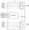
- the operation point selection unit 150 includes a candidate point speed comparison unit 151, a posture information switching unit 152, and a target speed switching unit 153.
- the candidate point speed comparator 151 compares the candidate point speed VTab input from the candidate point speed calculator 140 with the candidate point speed VTba, and if the candidate point speed VTab> the candidate point speed VTba (ie, the candidate point speed VTab) When the (second candidate point speed) is lower than the candidate point speed VTba (first candidate point speed), the bucket tip 8a is selected as the working point.
- the bucket back end 8b is selected as a working point.
- the work point selection unit 150 outputs which of the two work point candidates 8a and 8b has been selected as point selection information.
- point selection information a for switching the two two-position switches (posture information switching unit 152 and target speed switching unit 153) shown in FIG.
- the point output unit 2 outputs the point selection information b for switching the 2-position switch to the position b.
- FIG. 7 summarizes these relationships in a truth table.
- the posture information switching unit 152 outputs the posture information PIa relating to the bucket front end 8a as posture information when the work point indicated by the point selection information is the bucket front end 8a, and outputs the bucket back end 8b when the work point is the bucket back end 8b. Is output as posture information.
- the target speed switching unit 153 outputs the target speed VTa related to the bucket tip 8a as the target speed if the work point indicated by the point selection information is the bucket tip 8a, and outputs the bucket back end 8b if the work point is the bucket back end 8b. Is output as the target speed.
- the actuator speed calculation unit 130 uses the posture information and the target speed output from the work point selection unit 150 to set the target speed of the boom cylinder 5, arm cylinder 6, and bucket cylinder 7 necessary for operating the work point at the target speed. Is geometrically calculated and output to the control valve drive unit 200.
- the control valve drive unit 200 transmits a drive signal to the control valve 20 corresponding to each of the hydraulic cylinders 5, 6, 7 in order to achieve the target speed of the hydraulic cylinders 5, 6, 7 inputted from the information processing unit 100.
- a control valve drive signal is generated and output to the control valve 20.
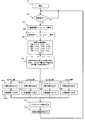
- FIG. 9 is a flowchart showing a flow of the calculation by the controller 500 described above.
- the controller 500 starts processing at a predetermined control cycle (procedure S1), and determines whether or not the operation levers 1c and 1d are operated based on the input operation signal (procedure S2). If the operation levers 1c and 1d are operated, the process proceeds to step S3. If not, the process waits until the operation levers 1c and 1d are operated.
- step S3 the deviation calculator 110 calculates the bucket tip 8a and the bucket back end 8b from the posture information PIa, PIb obtained from the posture sensors 13a, 13b, 13c, 13d and the target surface information obtained from the target surface setting device 18. And deviation information Da and Db between the target and the target plane 60 are calculated.
- step S4 the target speed calculator 120 calculates the target speeds VTa and VTb from the deviation information Da and Db, the posture information PIa and PIb, and the operation amount information obtained from the operation levers 1c and 1d. .
- step S5 when the candidate point speed calculation unit 140 operates a certain work point candidate 8a, 8b at the target speed VTa, VTb based on the target speeds VTa, VTb and the posture information PIa, PIb, The candidate point speeds VTba and VTab, which are the speeds of the work point candidates, are calculated.
- step S6 the work point selection unit 150 compares the two candidate point speeds VTab and VTba calculated in step S5, and selects a work point candidate corresponding to the candidate point speed having a large value as a work point. If the bucket tip 8a is selected as the work point, the procedure proceeds to step S7a, and if the bucket back end 8b is selected as the work point, the procedure proceeds to step S7b.
- step S7a the work point selection unit 150 outputs the posture information PIa regarding the work point 8a to the actuator speed calculation unit 130, and in the following step S8a, outputs the target speed VTa regarding the work point 8a to the actuator speed calculation unit 130. Proceed to S9.
- step S7b the work point selection unit 150 outputs the posture information PIb regarding the work point 8b to the actuator speed calculation unit 130, and in the following step S8b, outputs the target speed VTb regarding the work point 8b to the actuator speed calculation unit 130. Proceed to S9.
- step S9 the actuator speed calculation unit 130 calculates the command values of the boom cylinder speed, the arm cylinder speed, and the bucket cylinder speed by using the posture information PIa, PIb output by the work point selection unit 150 and the target speeds VTa, VTb as inputs. Then, the output is output to the control valve drive unit 200, and the procedure proceeds to step S10.
- step S10 the control valve driving unit 200 controls the hydraulic cylinders 5, 6, and 7 by generating a control valve drive signal corresponding to the boom cylinder speed, the arm cylinder speed, and the bucket cylinder speed calculated in step S9. Output to the control valve 20.
- the control valve 20 is driven by this drive signal to operate the hydraulic cylinders 5, 6, and 7, and the working device 15 is operated in accordance with the operation. Thereby, it is possible to prevent both of the two working point candidates 8a and 8b from entering the target surface 60.
- the target speeds VTa and VTb are respectively set based on the deviation information Da and Db from the target surface 60.
- the speeds (candidate point speeds) VTab and VTba generated in the other work point candidates are also calculated.
- a scene in which intrusion of a work point candidate that is not selected as a work point among the two work point candidates 8a and 8b into the target plane 60 poses a problem is caused by the two work point candidates 8a and 8b and the rotation center of the arm 12.
- the remaining work point candidates that are not selected as the work points among the two work point candidates 8a and 8b can be prevented from entering the target plane 60. It is possible to prevent the plurality of working point candidates 8a and 8b on the working device 15 from invading the target surface 60 even with respect to the target surface where the positions 8a and 8b are separated from each other. Thereby, the working accuracy and working efficiency of the hydraulic excavator can be improved.
- a target speed having a relatively small speed is selected by comparing the vertical components of the target speeds VTa and VTb of the two work point candidates 8a and 8b. If there is a candidate point speed lower than the selected target speed, another method such as selecting a work point candidate different from the work point candidate related to the candidate point speed as a work point is used. Is also good.
- the work point candidates of the bucket 8 are set at four points: a bucket left tip 8c, a bucket right tip 8d, a bucket left back end 8e, and a bucket right back end 8f. .
- This embodiment is effective for preventing the bucket 8 from entering the target surface 60 when, for example, a tilt type bucket is used as the bucket 8 or when the target surface 60 is not parallel to the boom rotation axis.
- the hardware configuration of the excavator 1 is the same as that of the first embodiment.
- the configuration (software configuration) of the information processing unit 100 in the controller 500 will be mainly described. However, a description of a configuration common to the first embodiment with respect to the configuration and arithmetic processing of the controller 500 may be omitted as appropriate.
- the controller 500 of the present embodiment also includes an information processing unit 100 and a control valve driving unit 200 as in the first embodiment.
- the information processing unit 100 includes a deviation calculation unit 110, a target speed calculation unit 120, and a candidate point speed calculation A section 140, a work point selecting section 150, and an actuator speed calculating section 130 are provided.
- the deviation calculator 110 calculates the position of the bucket left front end 8c, the position of the bucket right front end 8d, the position of the bucket left rear end 8e, and the position of the bucket right rear end 8f calculated from the posture information from the posture sensors 13a to 13d. From the input target plane information, the distance Dc between the bucket left front end 8c and the target plane 60, the distance Dd between the bucket right front end 8d and the target plane 60, and the distance De between the bucket left rear end 8e and the target plane 60 are determined. And the distance Df between the right rear end 8f of the bucket and the target plane 60 are calculated, and these are output as distance deviation information between the left and right ends of the bucket and the left and right rear ends.
- the target speed calculation unit 120 moves the bucket left and right front ends 8c and 8d and the left and right rear ends 8e and 8d along the target plane 60 based on the distance deviation information between the left and right front ends 8c and 8d and the left and right rear ends 8e and 8d. Calculate the velocities of the bucket left and right ends 8c and 8d and the left and right back ends 8e and 8d necessary for the target, and calculate the target speeds (VTc, VTd, VTe and VTf) of the bucket left and right ends 8c and 8d and the left and right back ends 8e and 8d. Output as
- FIG. 16 is a diagram illustrating the candidate point speed calculation unit 140 according to the second embodiment.
- the candidate point velocity calculator 140 includes geometric inverse transform units 141c, 141d, 141e, 141f and geometric transform units 142c, 142d, 142e, 142f.
- the geometric inverse transform units 141c, 141d, 141e, and 141f are provided with the attitude information of the left and right front ends 8c and 8d and the left and right rear ends 8e and 8d, and the target speed (VTc) of the left and right front ends 8c and 8d and the left and right rear ends 8e and 8d.
- VTd, VTe, VTf the rotation of the boom 11 and the arm 12 when the left and right front ends 8c, 8d and the left and right rear ends 8e, 8d operate at their own target speeds (VTc, VTd, VTe, VTf), respectively.
- the combination of the moving speeds (angular velocities) ⁇ c, ⁇ d, ⁇ e, ⁇ f is calculated.
- the geometric converters 142c, 142d, 142e, and 142f perform the remaining operations based on the combinations of the rotational speeds ⁇ c, ⁇ d, ⁇ e, and ⁇ f, and the posture information of the left and right front ends 8c and 8d and the left and right rear ends 8e and 8d.
- the candidate point speeds VTcd, VTce, VTcf, VTdc, VTde, VTdf, VTec, VTed, VTef, VTfc, VTfd, and VTfe, which are the point candidate speeds, are calculated.
- the candidate point speeds VTcd, VTce, and VTcf are the remaining three working point candidates (bucket right end 8d, bucket left back end 8e, and bucket right back end 8f) when the bucket left end 8c is operated at the target speed VTc.
- the velocities occurring in these three working point candidates are taken as one group (speed group), and a candidate point speed c is set as a set of candidate point velocities relating to the working point candidate 8c operated at the target speed VTc. It is called a group.
- the candidate point speeds VTdc, VTde, and VTdf are the speeds of the remaining three work point candidates when the bucket right end 8d is operated at the target speed VTd, and are hereinafter referred to as candidate point speed d groups.
- the candidate point speeds VTec, VTed, and VTef are referred to as a candidate point speed e group
- the candidate point speeds VTfc, VTfd, and VTfe are referred to as a candidate point speed f group.
- the candidate point speed calculation unit 140 determines the four working point candidates 8c, 8d, 8e, and 8f with the corresponding target among the four target speeds VTc, VTd, VTe, and VTf calculated by the target speed calculation unit 120.
- the speeds generated in the remaining three work point candidates are calculated, and the speeds generated in the remaining three work point candidates are grouped for each of the work point candidates to obtain four speed groups (candidate point speed c). Group-f group).
- the outputs of the geometric inverse transform units 141c, 141d, 141e, 141f are not the rotational speeds of the boom 11 and the arm 12, but the operating speeds of the boom cylinder 6 and the arm cylinder 7, and the geometric transform units 142c, 142d, You may comprise so that it may use as input of 142e, 142f.
- the work point selection unit 150 selects a speed group in which all of the work point candidates 8c-8f are most difficult to enter the target plane 60 from among the plurality of speed groups cf formed by the candidate point speed calculation unit 140. This is a part for performing a process of selecting one of the selected work points and selecting a work point candidate relating to the selected speed group as a work point (control point) of the semi-automatic excavation forming control. Specifically, the work point selection unit 150 selects a speed (ie, the lowest speed) that can enter the target surface 60 at the highest speed among the plurality of speed groups cf, and selects the plurality of speed groups cf.
- FIG. 17 is a diagram illustrating the work point selection unit 150 according to the second embodiment.
- the work point selection unit 150 includes a candidate point speed comparison unit 151, a posture information switching unit 152, and a target speed switching unit 153, as in the first embodiment.
- the candidate point speed comparison unit 151 selects the minimum value of the candidate point speeds cf (that is, the candidate point speeds that can invade the target plane 60 at the highest speed). Thereby, the minimum value of the candidate point speed c group, the minimum value of the candidate point speed d group, the minimum value of the candidate point speed e group, and the minimum value of the candidate point speed f group are selected.
- the candidate point speed comparison unit 151 calculates the minimum value of the candidate point speed c group, the minimum value of the candidate point speed d group, the minimum value of the candidate point speed e group, and the minimum value of the candidate point speed f group. And selects a speed group to which the maximum candidate point speed belongs from among the minimum values of the four.
- a work point candidate related to the selected speed group is set as a work point. That is, if the maximum candidate point speed is the minimum value of the group of candidate point velocities c, the bucket left end 8c is set as the working point, and if the maximum candidate point velocity is the minimum value of the group of candidate point velocities d, the bucket right end 8d is set.
- the maximum candidate point speed is the minimum value of the group of candidate point speeds e
- the bucket left rear end 8e is set as the work point
- the maximum candidate point speed is the minimum value of the group of candidate point speeds f
- the bucket right The rear end 8f is a working point.
- the work point selection unit 150 outputs which of the four work point candidates 8c to 8f is selected as point selection information.
- point selection information c for switching the two 4-position switches (posture information switching unit 152 and target speed switching unit 153) shown in FIG. 17 to the position c is output.
- the point selection information d for switching the 4-position switch to the position d is output.
- the left rear end 8e of the bucket is selected as the working point, the 4th position is output.
- the point selection information e for switching the switch to the position e is output, and when the bucket right rear end 8f is selected as the working point, the point selection information f for switching the 4-position switch to the position f is output.
- FIG. 14 summarizes these relationships in a truth table.
- the posture information switching unit 152 outputs the posture information PIc related to the bucket left end 8c when the work point indicated by the point selection information is the bucket left end 8c, and the posture related to the bucket right end 8d when the work point is the bucket back end 8d. If the work point is the bucket left back end 8e, the posture information PIe related to the bucket left back end 8e, if the work point is the bucket right back end 8f, the posture information PIf related to the bucket right back end 8f, Output as posture information.
- the target speed switching unit 153 sets the target speed VTc for the bucket left end 8c if the work point indicated by the point selection information is the bucket left end 8c, and sets the target speed VTc for the bucket right end 8d if the work point is the bucket back end 8d. If the work point is the bucket left back end 8e, the target speed VTe related to the bucket left back end 8e if the work point is the bucket right back end 8f, the target speed VTf related to the bucket right back end 8f if the work point is the bucket right back end 8f, Output as target speed.
- the actuator speed calculation unit 130 uses the posture information and the target speed output from the work point selection unit 150 to set the target speed of the boom cylinder 5, arm cylinder 6, and bucket cylinder 7 necessary for operating the work point at the target speed. Is geometrically calculated and output to the control valve drive unit 200.
- FIG. 15 is a flowchart showing the flow of the calculation by the controller 500 described above.
- the controller 500 starts processing at a predetermined control cycle (procedure S1), and determines whether or not the operation levers 1c and 1d are operated based on the input operation signal (procedure S2). If the operation levers 1c and 1d are operated, the process proceeds to step S3. If not, the process waits until the operation levers 1c and 1d are operated.
- step S3 the deviation calculating unit 110 calculates the bucket left and right tip 8c from the posture information PIc, PId, PIe, PIf obtained from the posture sensors 13a, 13b, 13c, 13d and the target surface information obtained from the target surface setting device 18. , 8d and the deviation information Dc, Dd, De, Df between the left and right rear ends 8e, 8d and the target plane 60 are calculated.
- step S4 the target speed calculator 120 calculates the deviation information Dc, Dd, De, Df, the posture information PIc, PId, PIe, PIf, and the operation amount information obtained from the operation levers 1c, 1d.
- the target speeds VTc, VTd, VTe, and VTf are calculated.
- the candidate point speed calculator 140 calculates certain work point candidates 8c, 8d, 8e, 8f from the target speeds VTc, VTd, VTe, VTf and the posture information PIc, PId, PIe, PIf.
- the candidate point speeds VTcd, VTce, VTcf, VTdc, VTde, VTdf, VTec, VTed, VTef, VTfc, VTfd, and VTfe which are the speeds of the other work point candidates, are calculated.
- the other three candidate point speeds VTcd, VTce, and VTcf are set at the candidate point speed c group, and when the work point candidate d is operated at the target speed VTd.
- the other three candidate point speeds VTdc, VTde, and VTdf are set to the candidate point speeds d, and the other three candidate point speeds VTec, VTed, and VTef when the work point candidate e is operated at the target speed VTe are set to the candidate point speeds e.
- the other three candidate point speeds VTfc, VTfd, and VTfe when the group and the work point candidate f are operated at the target speed VTf are defined as a candidate point speed f group.
- step S6 the work point selection unit 150 compares the minimum values of the groups of the candidate point speeds calculated in step S5, and sets a work point candidate corresponding to the candidate point speed having the largest value as a work point. select.
- the bucket left tip 8c is selected as a work point and the procedure goes to step S7c.
- the bucket right tip 8d is selected as a work point and the procedure goes to step S7d.
- the bucket left back end 8e is selected as a work point and the procedure goes to step S7e.
- the bucket right back end 8f is selected as a work point.
- step S7c the work point selection unit 150 outputs the posture information PIc regarding the bucket left front end 8c to the actuator speed calculation unit 130, and in the following step S8c, outputs the target speed VTc regarding the bucket left front end 8c to the actuator speed calculation unit 130. , Proceed to step S9. Similarly, in steps S7d-S7f and S8d-S8f, the posture information and the target speed related to the corresponding work point are selectively output.
- step S9 the actuator speed calculation unit 130 receives the posture information and the target speed output from the work point selection unit 150, and calculates and controls the corresponding command values of the boom cylinder speed, the arm cylinder speed, and the bucket cylinder speed. The output is output to the valve drive unit 200, and the process proceeds to step S10.
- step S10 the control valve driving unit 200 controls the hydraulic cylinders 5, 6, and 7 by generating a control valve drive signal corresponding to the boom cylinder speed, the arm cylinder speed, and the bucket cylinder speed calculated in step S9. Output to the control valve 20.
- the control valve 20 is driven by this drive signal to operate the hydraulic cylinders 5, 6, and 7, and the working device 15 is operated in accordance with the operation. Thus, it is possible to prevent any of the four working point candidates 8c-8f from invading the target surface 60.
- the target speeds VTc-VTf of the four working point candidates 8c-8f set in the working device 15 are respectively determined based on the deviation information Da-Df from the target surface 60. Calculating and moving the respective work point candidates 8a-8f at the target speeds VTa-VTf, the speeds (candidate point speeds) VTcd, VTce, VTcf, VTdc, VTde, VTdf, VTec, which occur in the remaining three work point candidates.
- VTed, VTef, VTfc, VTfd, and VTfe were also calculated, and the twelve candidate point speeds were divided into four groups (group c-f) for each of the four working point candidates 8c-8f. Then, in each of these four groups, the speed that can enter the target surface 60 earliest is selected, and one of the four speeds that can enter the target surface 60 the slowest is selected.
- the work point candidate relating to the speed group to which the speed that can enter the slowest belongs belongs is selected as the work point. When a work point is selected in this manner, the remaining work point candidates that have not been selected as the work points among the four work point candidates 8c-8f can be prevented from entering the target plane 60.
- the target surface 60 that is not uniform in the rotation axis direction of the work device 15.
- Semi-automatic digging can be performed on (for example, a target surface that is not parallel to the rotation axis of the working device 15) while preventing the leading edge and the rear edge of the bucket from entering the target surface 60.
- the present invention is not limited to the above embodiment, and includes various modifications without departing from the gist of the invention.
- the present invention is not limited to one having all the configurations described in the above embodiment, but also includes one in which a part of the configuration is deleted. Further, a part of the configuration according to one embodiment can be added to or replaced by the configuration according to another embodiment.
- the working device 15 is composed of the boom 11, the arm 12, and the bucket 8, and each has a rotating shaft in the same direction.
- other devices may be used.
- An example is a bucket having a rotary rotation axis or a tilt rotation axis.
- the four working point candidates are the vertices of the outer periphery of the bucket (the vertices of the four sides forming the bottom surface of the bucket).
- a work point candidate may be added to the target surface 60 having irregularities, for example, so that the work point candidate set on any one of the four sides can be prevented from coming into contact with the convex portion of the target surface 60. .
- the configuration related to the controller 500 may be a program (software) that is read and executed by an arithmetic processing unit (for example, a CPU) to realize each function related to the configuration of the controller 5005.
- Information related to the program can be stored in, for example, a semiconductor memory (flash memory, SSD, etc.), a magnetic storage device (hard disk drive, etc.), a recording medium (magnetic disk, optical disk, etc.), and the like.
- the system may be configured so that a part or all of the processing executed by the controller 500 is distributed and processed by a plurality of controllers and computers.
- Geometry conversion unit, 142b ... Geometry conversion unit, 142c ... Geometry conversion unit, 142d ... Geometry conversion unit, 142e ... Geometry conversion unit, 142f ... Geometry conversion unit, 150 ... Work point selection Unit, 151: candidate point speed comparison unit, 152: attitude information switching unit, 153: target speed switching unit, 200: control valve drive unit, 500: controller
Landscapes
- Engineering & Computer Science (AREA)
- Mining & Mineral Resources (AREA)
- Civil Engineering (AREA)
- General Engineering & Computer Science (AREA)
- Structural Engineering (AREA)
- Mechanical Engineering (AREA)
- Physics & Mathematics (AREA)
- Fluid Mechanics (AREA)
- Life Sciences & Earth Sciences (AREA)
- General Life Sciences & Earth Sciences (AREA)
- Paleontology (AREA)
- Operation Control Of Excavators (AREA)
Abstract
Description
<第1実施形態>
図1は本発明の第1実施形態に係る油圧ショベルを示す斜視図である。図1に示すように,本実施形態に係る油圧ショベルは,車体本体である下部走行体9および上部旋回体10と,上部旋回体10の前方に取り付けられた多関節型の作業装置(フロント作業装置)15とを備えている。
コントローラ500は,目標面設定装置18から目標面情報を受信して車体座標系上に設定した目標面60の位置情報と,車体座標系における作業装置15の姿勢情報と,操作レバー装置1の操作情報とに基づいて,作業装置15に設定した複数の作業点候補8a,8bを目標面60に沿って移動させる油圧シリンダ(ブームシリンダ)5の目標速度をそれぞれ演算し,その演算した複数の目標速度のうちいずれか1つの目標速度に従って油圧シリンダ(ブームシリンダ)5の速度を制御する処理を実行している。なお,本実施形態では,アームシリンダ6とバケットシリンダ7の速度は操作レバー装置1からコントロールバルブ20に対して出力される駆動信号に基づいて制御されている。
情報処理部100は,右操作レバー1c,左操作レバー1dから操作信号を受信し,第1姿勢センサ13a,第2姿勢センサ13b,第3姿勢センサ13c,及び車体姿勢センサ13dからそれぞれブーム11の姿勢情報(第1姿勢情報),アーム12の姿勢情報(第2姿勢情報),バケット8の姿勢情報(第3姿勢情報),及び車体姿勢情報を受信し,目標面設定装置18から車体座標系における目標面60の位置情報を受信し,アクチュエータ速度信号を演算して制御弁駆動部200に送信する。制御弁駆動部200は,情報処理部100で演算されたアクチュエータ速度信号に応じて制御弁駆動信号を生成・出力し,コントロールバルブ20を駆動する。
候補点速度演算部140は,複数の作業点候補8a,8bのそれぞれを,目標速度演算部120で演算した複数の目標速度のうち対応する目標速度で移動させた場合に残りの作業点候補に生じる速度(以下では「候補点速度」と称することがある)を演算する部分である。例えば,作業点候補8aをその目標速度VTaで移動させた場合に残りの作業点候補8bに生じる速度が候補点速度として候補点速度演算部140によって演算される。ここでは,作業点候補8aを目標速度VTaで移動させた場合に作業点候補8bに生じる速度を候補点速度VTabと称し,作業点候補8bを目標速度VTbで移動させた場合に作業点候補8aに生じる速度を候補点速度VTbaと称する。
作業点選択部150は,2つの候補点速度VTab,VTbaの中から2つ作業点候補8a,8bの全てが最も目標面60に侵入しづらい動作をする候補点速度を選出し,その選出した候補点速度に係る作業点候補を半自動掘削成形制御の作業点(制御点)として選択する処理を行う部分である。本実施形態の作業点選択部150は,2つの候補点速度VTab,VTbaの中から大きい方を選出し,その選出された候補点速度に係る作業点候補を作業点に決定している。
図9は,上述のコントローラ500による演算の流れを示したフローチャートである。コントローラ500は所定の制御周期で処理を開始し(手順S1),入力される操作信号に基づいて操作レバー1c,1dが操作されているか否かを判定する(手順S2)。ここで操作レバー1c,1dが操作されている場合には手順S3に進み,そうでない場合には操作レバー1c,1dが操作されるまで待機する。
以上のように構成した本実施形態の油圧ショベルでは,作業装置15に設定した2つの作業点候補8a,8bについて,目標面60との偏差情報Da,Dbに基づいて目標速度VTa,VTbをそれぞれ演算し,各作業点候補8a,8bを目標速度VTa,VTbで移動させる場合に他方の作業点候補に生じる速度(候補点速度)VTab,VTbaも演算することとした。2つの作業点候補8a,8bのうち作業点として選択されなかった作業点候補の目標面60への侵入が問題となる場面は,2つの作業点候補8a,8bとアーム12の回動中心との距離(各作業点候補8a,8bの回動半径)に差がある場合であり,一方の作業点候補を目標速度で動作させたときに他方の作業点候補の速度(候補点速度)がその目標速度よりも大きいときには,他方の作業点候補を目標速度で動作させたときの一方の作業点候補の速度(候補点速度)はその目標速度よりも小さくなる。そこで,2つの候補点速度VTab,VTbaのうち,より遅くに目標面60に侵入し得る候補点速度(すなわち,2つの候補点速度のうち大きさの大きい候補点速度)に係る作業点候補を作業点として選択することとした。このように作業点を選択すると,2つの作業点候補8a,8bのうち作業点として選択されなかった残りの作業点候補が目標面60に侵入することも防止できるので,ブーム下げによって作業点候補8a,8bが離れる位置にある目標面についても,作業装置15上の複数の作業点候補8a,8bが目標面60に侵入することを防止できる。これにより油圧ショベルによる作業精度と作業効率を向上できる。
以下,本発明の第2の実施形態について説明する。本実施形態は,バケット8の作業点候補を,図13に示すように,バケット左先端8c,バケット右先端8d,バケット左背面端8e,バケット右背面端8fの4点に設定したものである。本実施形態は,例えばバケット8にチルト式バケットを利用した場合や,目標面60がブーム回動軸と平行でない場合等にバケット8の目標面60への侵入防止に有効である。なお,油圧ショベル1のハードウェア構成は第1実施形態と同じであり,ここではコントローラ500内の情報処理部100の構成(ソフトウェア構成)について主に説明する。ただし,コントローラ500の構成や演算処理に関して第1実施形態と共通する部分の説明については適宜省略することがある。
図16は,第2実施形態における候補点速度演算部140を示す図である。候補点速度演算部140は,第1の実施形態と同様,幾何学逆変換部141c,141d,141e,141fと,幾何学変換部142c,142d,142e,142fとを備える。
作業点選択部150は,候補点速度演算部140で形成された複数の速度群c-fの中から,作業点候補8c-8fの全てが最も目標面60に侵入しづらい動作をする速度群を1つ選出し,その選出した速度群に係る作業点候補を半自動掘削成形制御の作業点(制御点)として選択する処理を行う部分である。具体的には,作業点選択部150は,複数の速度群c-fのそれぞれで目標面60に最も速く侵入し得る速度(すなわち,最も小さい速度)を選出し,複数の速度群c-fから選出された目標面60に最も速く侵入し得る速度の中で目標面60に最も遅く侵入し得る速度(すなわち,最も大きい速度)を選出し,複数の速度群c-fの中から目標面60に最も遅く侵入し得る速度が属する速度群を選出することで,作業点候補8c-8fの全てが最も目標面60に侵入しづらい動作をする速度群を選出している。以下,作業点選択部150のさらに詳細な処理内容について説明する。
図15は,上述のコントローラ500による演算の流れを示したフローチャートである。コントローラ500は,所定の制御周期で処理を開始し(手順S1),入力される操作信号に基づいて操作レバー1c,1dが操作されているか否かを判定する(手順S2)。ここで操作レバー1c,1dが操作されている場合には手順S3に進み,そうでない場合には操作レバー1c,1dが操作されるまで待機する。
以上のように構成した本実施形態の油圧ショベルでは,作業装置15に設定した4つの作業点候補8c-8fについて,目標面60との偏差情報Da-Dfに基づいて目標速度VTc-VTfをそれぞれ演算し,各作業点候補8a-8fを目標速度VTa-VTfで移動させる場合に残りの3つの作業点候補に生じる速度(候補点速度)VTcd,VTce,VTcf,VTdc,VTde,VTdf,VTec,VTed,VTef,VTfc,VTfd,VTfeも演算し,その12の候補点速度を4つの作業点候補8c-8fごとに4つのグループ(c群-f群)に分けた。そして,この4つのグループのそれぞれで目標面60に最も早く侵入し得る速度を選出し,その選出された4つの速度の中で目標面60に最も遅く侵入し得る速度を1つ選出し,その最も遅く侵入し得る速度が属する速度群に係る作業点候補を作業点として選択することとした。このように作業点を選択すると,4つの作業点候補8c-8fのうち作業点として選択されなかった残りの作業点候補が目標面60に侵入することも防止できるので,ブーム下げによって作業点候補8c-8fが離れる位置にある目標面についても,作業装置15上の複数の作業点候補8c-8fが目標面60に侵入することを防止できる。これにより油圧ショベルによる作業精度と作業効率を向上できる。
本発明は,上記の実施の形態に限定されるものではなく,その要旨を逸脱しない範囲内の様々な変形例が含まれる。例えば,本発明は,上記の実施の形態で説明した全ての構成を備えるものに限定されず,その構成の一部を削除したものも含まれる。また,ある実施の形態に係る構成の一部を,他の実施の形態に係る構成に追加又は置換することが可能である。
Claims (5)
- 作業装置と,
油圧ポンプから吐出される作動油によって駆動され前記作業装置を動作させる油圧シリンダと,
オペレータの操作に応じて前記油圧シリンダの動作を指示する操作装置と,
任意に設定された目標面の位置情報と前記作業装置の姿勢情報と前記操作装置の操作情報とに基づいて,前記作業装置に設定した複数の作業点候補を前記目標面に沿って移動させる前記油圧シリンダの目標速度をそれぞれ演算し,その演算した複数の目標速度のうちいずれか1つの目標速度に従って前記油圧シリンダの速度を制御するコントローラとを備えた作業機械において,
前記コントローラは,
前記複数の作業点候補のそれぞれを,前記複数の目標速度のうち対応する目標速度で移動させた場合に残りの作業点候補に生じる速度を演算し,
前記残りの作業点候補に生じる速度を前記複数の作業点候補ごとにグルーピングして複数の速度群をつくり,
前記複数の速度群の中から前記複数の作業点候補の全てが最も前記目標面に侵入しづらい動作をする速度群を選出し,
前記複数の目標速度のうち,前記選出した速度群に係る作業点候補の目標速度に従って前記油圧シリンダを制御することを特徴とする作業機械。 - 請求項1の作業機械において,
前記コントローラは,
前記複数の作業点候補のそれぞれを,前記複数の目標速度のうち対応する目標速度で移動させた場合に残りの作業点候補に生じる速度を演算し,
前記残りの作業点候補に生じる速度を前記複数の作業点候補ごとにグルーピングして複数の速度群をつくり,
前記複数の速度群のそれぞれで前記目標面に最も速く侵入し得る速度を選出し,
前記複数の速度群から選出された前記目標面に最も速く侵入し得る速度の中で前記目標面に最も遅く侵入し得る速度を選出し,
前記複数の速度群の中から前記目標面に最も遅く侵入し得る速度が属する速度群を選出し,
前記複数の目標速度のうち,前記選出した速度群に係る作業点候補の目標速度に従って前記油圧シリンダを制御することを特徴とする作業機械。 - 請求項2の作業機械において,
前記目標面から遠ざかる速度の方向を正としたとき,
前記目標面に最も速く侵入し得る速度とは,最も小さい速度であり,
前記目標面に最も速く侵入し得る速度とは,最も大きい速度であることを特徴とする作業機械。 - 請求項1の作業機械において,
前記複数の作業点候補として,前記作業装置には第1作業点候補と第2作業点候補が設定されており,
前記コントローラは,
前記複数の目標速度のうち前記第2作業点候補の目標速度で前記第2作業点候補を移動させた場合に前記第1作業点候補に生じる速度である第1候補点速度を演算し,
前記複数の目標速度のうち前記第1作業点候補の目標速度で前記第1作業点候補を移動させた場合に前記第2作業点候補に生じる速度である第2候補点速度を演算し,
前記第1候補点速度が前記第2候補点速度よりも前記目標面に侵入しづらい速度のときには前記第2作業点候補の目標速度に従って前記油圧シリンダを制御し,
前記第2候補点速度が前記第1候補点速度よりも前記目標面に侵入しづらい速度のときには前記第1作業点候補の目標速度に従って前記油圧シリンダを制御することを特徴とする作業機械。 - 請求項4の作業機械において,
前記作業装置はバケットを有し,
前記第1作業点候補は前記バケットの先端縁上に設定された点であり,
前記第2作業点候補は前記バケットの背面端縁上に設定された点であることを特徴とする作業機械。
Priority Applications (6)
| Application Number | Priority Date | Filing Date | Title |
|---|---|---|---|
| CN201880055757.7A CN111201350B (zh) | 2018-09-20 | 2018-09-20 | 作业机械 |
| KR1020207005100A KR102388106B1 (ko) | 2018-09-20 | 2018-09-20 | 작업 기계 |
| PCT/JP2018/034896 WO2020059094A1 (ja) | 2018-09-20 | 2018-09-20 | 作業機械 |
| US16/645,501 US11377813B2 (en) | 2018-09-20 | 2018-09-20 | Work machine with semi-automatic excavation and shaping |
| JP2020509552A JP6826234B2 (ja) | 2018-09-20 | 2018-09-20 | 作業機械 |
| EP18932317.3A EP3854946B1 (en) | 2018-09-20 | 2018-09-20 | Work machine |
Applications Claiming Priority (1)
| Application Number | Priority Date | Filing Date | Title |
|---|---|---|---|
| PCT/JP2018/034896 WO2020059094A1 (ja) | 2018-09-20 | 2018-09-20 | 作業機械 |
Publications (1)
| Publication Number | Publication Date |
|---|---|
| WO2020059094A1 true WO2020059094A1 (ja) | 2020-03-26 |
Family
ID=69888624
Family Applications (1)
| Application Number | Title | Priority Date | Filing Date |
|---|---|---|---|
| PCT/JP2018/034896 Ceased WO2020059094A1 (ja) | 2018-09-20 | 2018-09-20 | 作業機械 |
Country Status (6)
| Country | Link |
|---|---|
| US (1) | US11377813B2 (ja) |
| EP (1) | EP3854946B1 (ja) |
| JP (1) | JP6826234B2 (ja) |
| KR (1) | KR102388106B1 (ja) |
| CN (1) | CN111201350B (ja) |
| WO (1) | WO2020059094A1 (ja) |
Cited By (1)
| Publication number | Priority date | Publication date | Assignee | Title |
|---|---|---|---|---|
| US20220178113A1 (en) * | 2019-04-05 | 2022-06-09 | Volvo Construction Equipment Ab | Construction equipment |
Families Citing this family (3)
| Publication number | Priority date | Publication date | Assignee | Title |
|---|---|---|---|---|
| EP3882400B1 (en) * | 2018-11-14 | 2026-04-29 | Sumitomo Heavy Industries, Ltd. | Shovel and device for controlling shovel |
| JP7089550B2 (ja) * | 2020-06-16 | 2022-06-22 | 日立建機株式会社 | 建設機械 |
| US20250163670A1 (en) * | 2023-11-16 | 2025-05-22 | Kubota Corporation | Working machine |
Citations (5)
| Publication number | Priority date | Publication date | Assignee | Title |
|---|---|---|---|---|
| JP2000192514A (ja) * | 1998-12-28 | 2000-07-11 | Hitachi Constr Mach Co Ltd | 自動運転建設機械およびその運転方法 |
| WO2012127914A1 (ja) | 2011-03-24 | 2012-09-27 | 株式会社小松製作所 | 掘削制御システム |
| WO2015181990A1 (ja) * | 2014-05-30 | 2015-12-03 | 株式会社小松製作所 | 作業機械の制御システム、作業機械、油圧ショベルの制御システム及び作業機械の制御方法 |
| JP2016003442A (ja) * | 2014-06-13 | 2016-01-12 | 日立建機株式会社 | 建設機械の掘削制御装置 |
| WO2016186219A1 (ja) * | 2016-05-31 | 2016-11-24 | 株式会社小松製作所 | 建設機械の制御システム、建設機械、及び建設機械の制御方法 |
Family Cites Families (10)
| Publication number | Priority date | Publication date | Assignee | Title |
|---|---|---|---|---|
| JP3609164B2 (ja) * | 1995-08-14 | 2005-01-12 | 日立建機株式会社 | 建設機械の領域制限掘削制御の掘削領域設定装置 |
| JPH10159123A (ja) * | 1996-12-03 | 1998-06-16 | Shin Caterpillar Mitsubishi Ltd | 建設機械の制御装置 |
| US7532967B2 (en) * | 2002-09-17 | 2009-05-12 | Hitachi Construction Machinery Co., Ltd. | Excavation teaching apparatus for construction machine |
| CN103354855B (zh) * | 2011-03-24 | 2016-08-10 | 株式会社小松制作所 | 挖掘控制系统及建筑机械 |
| JP5237408B2 (ja) * | 2011-03-24 | 2013-07-17 | 株式会社小松製作所 | 油圧ショベルの較正システム及び較正方法 |
| JP5848451B1 (ja) * | 2014-06-02 | 2016-01-27 | 株式会社小松製作所 | 建設機械の制御システム、建設機械、及び建設機械の制御方法 |
| US9834905B2 (en) * | 2015-09-25 | 2017-12-05 | Komatsu Ltd. | Work machine control device, work machine, and work machine control method |
| JP6506205B2 (ja) * | 2016-03-31 | 2019-04-24 | 日立建機株式会社 | 建設機械 |
| US10196796B2 (en) * | 2016-05-31 | 2019-02-05 | Komatsu Ltd. | Construction machine control system, construction machine, and construction machine control method |
| WO2017104408A1 (ja) * | 2016-11-29 | 2017-06-22 | 株式会社小松製作所 | 作業機制御装置および作業機械 |
-
2018
- 2018-09-20 JP JP2020509552A patent/JP6826234B2/ja active Active
- 2018-09-20 EP EP18932317.3A patent/EP3854946B1/en active Active
- 2018-09-20 CN CN201880055757.7A patent/CN111201350B/zh active Active
- 2018-09-20 KR KR1020207005100A patent/KR102388106B1/ko active Active
- 2018-09-20 US US16/645,501 patent/US11377813B2/en active Active
- 2018-09-20 WO PCT/JP2018/034896 patent/WO2020059094A1/ja not_active Ceased
Patent Citations (5)
| Publication number | Priority date | Publication date | Assignee | Title |
|---|---|---|---|---|
| JP2000192514A (ja) * | 1998-12-28 | 2000-07-11 | Hitachi Constr Mach Co Ltd | 自動運転建設機械およびその運転方法 |
| WO2012127914A1 (ja) | 2011-03-24 | 2012-09-27 | 株式会社小松製作所 | 掘削制御システム |
| WO2015181990A1 (ja) * | 2014-05-30 | 2015-12-03 | 株式会社小松製作所 | 作業機械の制御システム、作業機械、油圧ショベルの制御システム及び作業機械の制御方法 |
| JP2016003442A (ja) * | 2014-06-13 | 2016-01-12 | 日立建機株式会社 | 建設機械の掘削制御装置 |
| WO2016186219A1 (ja) * | 2016-05-31 | 2016-11-24 | 株式会社小松製作所 | 建設機械の制御システム、建設機械、及び建設機械の制御方法 |
Non-Patent Citations (1)
| Title |
|---|
| See also references of EP3854946A4 |
Cited By (1)
| Publication number | Priority date | Publication date | Assignee | Title |
|---|---|---|---|---|
| US20220178113A1 (en) * | 2019-04-05 | 2022-06-09 | Volvo Construction Equipment Ab | Construction equipment |
Also Published As
| Publication number | Publication date |
|---|---|
| CN111201350A (zh) | 2020-05-26 |
| JPWO2020059094A1 (ja) | 2020-12-17 |
| EP3854946A4 (en) | 2022-05-04 |
| EP3854946B1 (en) | 2024-01-10 |
| US20210148081A1 (en) | 2021-05-20 |
| US11377813B2 (en) | 2022-07-05 |
| KR102388106B1 (ko) | 2022-04-19 |
| KR20200034763A (ko) | 2020-03-31 |
| JP6826234B2 (ja) | 2021-02-03 |
| EP3854946A1 (en) | 2021-07-28 |
| CN111201350B (zh) | 2022-02-25 |
Similar Documents
| Publication | Publication Date | Title |
|---|---|---|
| CN108699799B (zh) | 作业机械 | |
| JP6053714B2 (ja) | 油圧ショベル | |
| JP6826234B2 (ja) | 作業機械 | |
| JP6511387B2 (ja) | 建設機械の制御装置 | |
| CN113454293B (zh) | 作业机械 | |
| WO2018008188A1 (ja) | 作業機械 | |
| CN111032962B (zh) | 工程机械 | |
| WO2022163168A1 (ja) | 作業機械 | |
| WO2019202673A1 (ja) | 作業機械 | |
| WO2022201623A1 (ja) | 作業機械 | |
| JP6615058B2 (ja) | 作業機械 | |
| JP7113148B2 (ja) | 作業機械 | |
| WO2022224624A1 (ja) | 作業機械 | |
| JP2022157472A (ja) | 建設機械 | |
| JP7269301B2 (ja) | 作業機械 | |
| JP2024137906A (ja) | オフセットジョイントを備えた作業機械用の装置、オフセット掘削機を制御するための方法及び装置 | |
| WO2020065739A1 (ja) | 作業機械 | |
| CN117738256A (zh) | 一种挖掘机控制方法、装置及挖掘机 | |
| WO2024171607A1 (ja) | 作業機械 |
Legal Events
| Date | Code | Title | Description |
|---|---|---|---|
| ENP | Entry into the national phase |
Ref document number: 2020509552 Country of ref document: JP Kind code of ref document: A |
|
| ENP | Entry into the national phase |
Ref document number: 20207005100 Country of ref document: KR Kind code of ref document: A |
|
| 121 | Ep: the epo has been informed by wipo that ep was designated in this application |
Ref document number: 18932317 Country of ref document: EP Kind code of ref document: A1 |
|
| NENP | Non-entry into the national phase |
Ref country code: DE |
|
| ENP | Entry into the national phase |
Ref document number: 2018932317 Country of ref document: EP Effective date: 20210420 |