WO2020059632A1 - Dispositif amortisseur et procédé de conception associé - Google Patents
Dispositif amortisseur et procédé de conception associé Download PDFInfo
- Publication number
- WO2020059632A1 WO2020059632A1 PCT/JP2019/035931 JP2019035931W WO2020059632A1 WO 2020059632 A1 WO2020059632 A1 WO 2020059632A1 JP 2019035931 W JP2019035931 W JP 2019035931W WO 2020059632 A1 WO2020059632 A1 WO 2020059632A1
- Authority
- WO
- WIPO (PCT)
- Prior art keywords
- damper device
- output
- input
- inertia
- output element
- Prior art date
- Legal status (The legal status is an assumption and is not a legal conclusion. Google has not performed a legal analysis and makes no representation as to the accuracy of the status listed.)
- Ceased
Links
Images



Classifications
-
- F—MECHANICAL ENGINEERING; LIGHTING; HEATING; WEAPONS; BLASTING
- F16—ENGINEERING ELEMENTS AND UNITS; GENERAL MEASURES FOR PRODUCING AND MAINTAINING EFFECTIVE FUNCTIONING OF MACHINES OR INSTALLATIONS; THERMAL INSULATION IN GENERAL
- F16D—COUPLINGS FOR TRANSMITTING ROTATION; CLUTCHES; BRAKES
- F16D3/00—Yielding couplings, i.e. with means permitting movement between the connected parts during the drive
- F16D3/02—Yielding couplings, i.e. with means permitting movement between the connected parts during the drive adapted to specific functions
- F16D3/12—Yielding couplings, i.e. with means permitting movement between the connected parts during the drive adapted to specific functions specially adapted for accumulation of energy to absorb shocks or vibration
-
- F—MECHANICAL ENGINEERING; LIGHTING; HEATING; WEAPONS; BLASTING
- F16—ENGINEERING ELEMENTS AND UNITS; GENERAL MEASURES FOR PRODUCING AND MAINTAINING EFFECTIVE FUNCTIONING OF MACHINES OR INSTALLATIONS; THERMAL INSULATION IN GENERAL
- F16F—SPRINGS; SHOCK-ABSORBERS; MEANS FOR DAMPING VIBRATION
- F16F15/00—Suppression of vibrations in systems; Means or arrangements for avoiding or reducing out-of-balance forces, e.g. due to motion
- F16F15/10—Suppression of vibrations in rotating systems by making use of members moving with the system
- F16F15/12—Suppression of vibrations in rotating systems by making use of members moving with the system using elastic members or friction-damping members, e.g. between a rotating shaft and a gyratory mass mounted thereon
- F16F15/121—Suppression of vibrations in rotating systems by making use of members moving with the system using elastic members or friction-damping members, e.g. between a rotating shaft and a gyratory mass mounted thereon using springs as elastic members, e.g. metallic springs
- F16F15/123—Wound springs
- F16F15/12353—Combinations of dampers, e.g. with multiple plates, multiple spring sets, i.e. complex configurations
- F16F15/1236—Combinations of dampers, e.g. with multiple plates, multiple spring sets, i.e. complex configurations resulting in a staged spring characteristic, e.g. with multiple intermediate plates
- F16F15/12366—Combinations of dampers, e.g. with multiple plates, multiple spring sets, i.e. complex configurations resulting in a staged spring characteristic, e.g. with multiple intermediate plates acting on multiple sets of springs
-
- F—MECHANICAL ENGINEERING; LIGHTING; HEATING; WEAPONS; BLASTING
- F02—COMBUSTION ENGINES; HOT-GAS OR COMBUSTION-PRODUCT ENGINE PLANTS
- F02N—STARTING OF COMBUSTION ENGINES; STARTING AIDS FOR SUCH ENGINES, NOT OTHERWISE PROVIDED FOR
- F02N7/00—Starting apparatus having fluid-driven auxiliary engines or apparatus
-
- F—MECHANICAL ENGINEERING; LIGHTING; HEATING; WEAPONS; BLASTING
- F16—ENGINEERING ELEMENTS AND UNITS; GENERAL MEASURES FOR PRODUCING AND MAINTAINING EFFECTIVE FUNCTIONING OF MACHINES OR INSTALLATIONS; THERMAL INSULATION IN GENERAL
- F16F—SPRINGS; SHOCK-ABSORBERS; MEANS FOR DAMPING VIBRATION
- F16F15/00—Suppression of vibrations in systems; Means or arrangements for avoiding or reducing out-of-balance forces, e.g. due to motion
- F16F15/10—Suppression of vibrations in rotating systems by making use of members moving with the system
- F16F15/12—Suppression of vibrations in rotating systems by making use of members moving with the system using elastic members or friction-damping members, e.g. between a rotating shaft and a gyratory mass mounted thereon
- F16F15/121—Suppression of vibrations in rotating systems by making use of members moving with the system using elastic members or friction-damping members, e.g. between a rotating shaft and a gyratory mass mounted thereon using springs as elastic members, e.g. metallic springs
- F16F15/1217—Motion-limiting means, e.g. means for locking the spring unit in pre-defined positions
-
- F—MECHANICAL ENGINEERING; LIGHTING; HEATING; WEAPONS; BLASTING
- F16—ENGINEERING ELEMENTS AND UNITS; GENERAL MEASURES FOR PRODUCING AND MAINTAINING EFFECTIVE FUNCTIONING OF MACHINES OR INSTALLATIONS; THERMAL INSULATION IN GENERAL
- F16F—SPRINGS; SHOCK-ABSORBERS; MEANS FOR DAMPING VIBRATION
- F16F15/00—Suppression of vibrations in systems; Means or arrangements for avoiding or reducing out-of-balance forces, e.g. due to motion
- F16F15/10—Suppression of vibrations in rotating systems by making use of members moving with the system
- F16F15/12—Suppression of vibrations in rotating systems by making use of members moving with the system using elastic members or friction-damping members, e.g. between a rotating shaft and a gyratory mass mounted thereon
- F16F15/131—Suppression of vibrations in rotating systems by making use of members moving with the system using elastic members or friction-damping members, e.g. between a rotating shaft and a gyratory mass mounted thereon the rotating system comprising two or more gyratory masses
- F16F15/133—Suppression of vibrations in rotating systems by making use of members moving with the system using elastic members or friction-damping members, e.g. between a rotating shaft and a gyratory mass mounted thereon the rotating system comprising two or more gyratory masses using springs as elastic members, e.g. metallic springs
- F16F15/134—Wound springs
- F16F15/13469—Combinations of dampers, e.g. with multiple plates, multiple spring sets, i.e. complex configurations
-
- F—MECHANICAL ENGINEERING; LIGHTING; HEATING; WEAPONS; BLASTING
- F16—ENGINEERING ELEMENTS AND UNITS; GENERAL MEASURES FOR PRODUCING AND MAINTAINING EFFECTIVE FUNCTIONING OF MACHINES OR INSTALLATIONS; THERMAL INSULATION IN GENERAL
- F16H—GEARING
- F16H45/00—Combinations of fluid gearings for conveying rotary motion with couplings or clutches
- F16H45/02—Combinations of fluid gearings for conveying rotary motion with couplings or clutches with mechanical clutches for bridging a fluid gearing of the hydrokinetic type
-
- F—MECHANICAL ENGINEERING; LIGHTING; HEATING; WEAPONS; BLASTING
- F16—ENGINEERING ELEMENTS AND UNITS; GENERAL MEASURES FOR PRODUCING AND MAINTAINING EFFECTIVE FUNCTIONING OF MACHINES OR INSTALLATIONS; THERMAL INSULATION IN GENERAL
- F16F—SPRINGS; SHOCK-ABSORBERS; MEANS FOR DAMPING VIBRATION
- F16F2226/00—Manufacturing; Treatments
-
- F—MECHANICAL ENGINEERING; LIGHTING; HEATING; WEAPONS; BLASTING
- F16—ENGINEERING ELEMENTS AND UNITS; GENERAL MEASURES FOR PRODUCING AND MAINTAINING EFFECTIVE FUNCTIONING OF MACHINES OR INSTALLATIONS; THERMAL INSULATION IN GENERAL
- F16F—SPRINGS; SHOCK-ABSORBERS; MEANS FOR DAMPING VIBRATION
- F16F2228/00—Functional characteristics, e.g. variability, frequency-dependence
- F16F2228/001—Specific functional characteristics in numerical form or in the form of equations
-
- F—MECHANICAL ENGINEERING; LIGHTING; HEATING; WEAPONS; BLASTING
- F16—ENGINEERING ELEMENTS AND UNITS; GENERAL MEASURES FOR PRODUCING AND MAINTAINING EFFECTIVE FUNCTIONING OF MACHINES OR INSTALLATIONS; THERMAL INSULATION IN GENERAL
- F16F—SPRINGS; SHOCK-ABSORBERS; MEANS FOR DAMPING VIBRATION
- F16F2228/00—Functional characteristics, e.g. variability, frequency-dependence
- F16F2228/001—Specific functional characteristics in numerical form or in the form of equations
- F16F2228/005—Material properties, e.g. moduli
- F16F2228/007—Material properties, e.g. moduli of solids, e.g. hardness
-
- F—MECHANICAL ENGINEERING; LIGHTING; HEATING; WEAPONS; BLASTING
- F16—ENGINEERING ELEMENTS AND UNITS; GENERAL MEASURES FOR PRODUCING AND MAINTAINING EFFECTIVE FUNCTIONING OF MACHINES OR INSTALLATIONS; THERMAL INSULATION IN GENERAL
- F16F—SPRINGS; SHOCK-ABSORBERS; MEANS FOR DAMPING VIBRATION
- F16F2232/00—Nature of movement
- F16F2232/02—Rotary
-
- F—MECHANICAL ENGINEERING; LIGHTING; HEATING; WEAPONS; BLASTING
- F16—ENGINEERING ELEMENTS AND UNITS; GENERAL MEASURES FOR PRODUCING AND MAINTAINING EFFECTIVE FUNCTIONING OF MACHINES OR INSTALLATIONS; THERMAL INSULATION IN GENERAL
- F16F—SPRINGS; SHOCK-ABSORBERS; MEANS FOR DAMPING VIBRATION
- F16F2236/00—Mode of stressing of basic spring or damper elements or devices incorporating such elements
- F16F2236/08—Torsion
-
- F—MECHANICAL ENGINEERING; LIGHTING; HEATING; WEAPONS; BLASTING
- F16—ENGINEERING ELEMENTS AND UNITS; GENERAL MEASURES FOR PRODUCING AND MAINTAINING EFFECTIVE FUNCTIONING OF MACHINES OR INSTALLATIONS; THERMAL INSULATION IN GENERAL
- F16H—GEARING
- F16H45/00—Combinations of fluid gearings for conveying rotary motion with couplings or clutches
- F16H45/02—Combinations of fluid gearings for conveying rotary motion with couplings or clutches with mechanical clutches for bridging a fluid gearing of the hydrokinetic type
- F16H2045/0221—Combinations of fluid gearings for conveying rotary motion with couplings or clutches with mechanical clutches for bridging a fluid gearing of the hydrokinetic type with damping means
- F16H2045/0226—Combinations of fluid gearings for conveying rotary motion with couplings or clutches with mechanical clutches for bridging a fluid gearing of the hydrokinetic type with damping means comprising two or more vibration dampers
Definitions
- the present disclosure relates to a damper device including an input element to which torque from an engine is transmitted, an output element connected to an input shaft of a transmission, and an elastic body that transmits torque between the input element and the output element. Regarding the design method.
- a front cover connected to an input rotary shaft (engine), a pump impeller forming a fluid transmission chamber together with the front cover, a turbine runner having a convex portion formed on the front cover side, the turbine runner and an output Including a turbine hub (supporting member) connected to the rotating shaft, a direct connection clutch capable of connecting the front cover and the turbine hub, and a damper device for damping vibration between a piston plate of the direct connection clutch and the turbine hub.
- a fluid transmission device is known (for example, see Patent Document 1).
- the turbine hub of the fluid transmission device is enlarged in diameter so as to fill a space between the turbine runner and the damper device, and includes a concave portion formed on the turbine runner side.
- the concave portion of the turbine hub and the convex portion of the turbine runner are connected to each other by brazing, and the turbine hub functions as an inertial mass body.
- a drive member to which power from an engine as a prime mover is transmitted a first intermediate member to which power is transmitted from the drive member via a first spring, and a first intermediate member via a second spring.
- a damper device including a second intermediate member to which power is transmitted and a driven member to which power is transmitted from the second intermediate member via a third spring is known (for example, see Patent Document 2).
- the rigidity (equivalent rigidity) of the entire damper device that is, the combined spring constant of the first, second, and third springs is made smaller to further improve the vibration damping performance. Can be.
- the structure becomes complicated and the number of components increases, making it difficult to suppress an increase in cost.
- the present disclosure has a main object of suppressing a decrease in the vibration damping performance of a damper device in a low rotation speed range while suppressing an increase in cost, and reducing the engagement rotation speed of a clutch connecting the engine and the damper device.
- the damper device of the present disclosure is arranged between an input element connected to an engine via a clutch, an intermediate element, an output element connected to an input shaft of a transmission, and the input element and the intermediate element.
- a damper device comprising: a first elastic body having a first elastic body, and a second elastic body disposed between the intermediate element and the output element and acting in series with the first elastic body.
- the present inventors have conducted intensive studies to improve the vibration damping performance of the damper device including the input element, the intermediate element, the output element, and the first and second elastic bodies.
- the output element of the damper device and the transmission total moment of inertia of all rotating members included between the total moment of inertia J 2 of the rotating element which rotates together with the output element in the engine side of the input shaft to a differential gear from the input shaft of the transmission focusing on the relationship between J TM.
- the present inventors have found that the moment of inertia J 2 and moment of inertia J sum of the TM ratio of moment of inertia J 2 for (J 2 + J TM) J 2 / (J 2 + J TM) is 0.12 ⁇ J 2 /
- the damper device so as to satisfy (J 2 + J TM ) ⁇ 0.5, it is possible to suppress a decrease in the vibration damping performance of the damper device due to resonance on a higher frequency side than the engagement rotation speed of the clutch, and to reduce the engagement rotation speed. It has been found that the resonance on the lower frequency side than the number can be shifted to the lower frequency side.
- the damper device of the present disclosure while suppressing the increase in cost due to the addition of the second intermediate element and the elastic body, the reduction of the vibration damping performance in the low rotation range is suppressed, and the engine and the damper device are connected. It is possible to reduce the rotational speed of the clutch.
- another damper device of the present disclosure is provided with an input element connected to an engine via a clutch, an output element connected to an input shaft of a transmission, and disposed between the input element and the output element.
- the damper device includes a plurality of elastic members, and the output element, the total moment of inertia of the rotating element rotating integrally with the output element in the engine side of said input shaft and J 2, the input shaft the total moment of inertia of all rotating members included until differential gear connected to an output shaft of the transmission when the J TM from 0.12 ⁇ J 2 / (J 2 + J TM ) ⁇ 0.55 It satisfies.
- the present inventors have conducted intensive studies to improve the vibration damping performance of a damper device including an input element, an output element, and a plurality of elastic bodies disposed therebetween, and as a result, the damper device has an inertia.
- moment J 2 and the sum of the moment of inertia J TM (J 2 + J TM ) ratio of moment of inertia J 2 for J 2 / (J 2 + J TM) is 0.12 ⁇ J 2 / (J 2 + J TM) ⁇ 0. 55, while suppressing the reduction of the vibration damping performance of the damper device due to the resonance on the higher frequency side than the engagement rotation speed of the clutch, the resonance on the lower frequency side than the engagement rotation speed is reduced to a lower frequency.
- FIG. 1 is a schematic configuration diagram illustrating a starting device including a damper device according to the present disclosure.
- 1 is a partial cross-sectional view illustrating a damper device according to the present disclosure.
- the ratio J 2 / moment of inertia J 2 to the sum of the moment of inertia J 2 and moment of inertia J TM (J 2 + J TM ), is a table showing the relationship between the lock-up permissible rotational speed.
- 5 is a chart illustrating a relationship between an engine speed and a torque fluctuation of an output element of the damper device.
- FIG. 11 is a partial cross-sectional view illustrating a damper device including another mass body according to the present disclosure.
- FIG. 11 is a schematic configuration diagram illustrating another damper device of the present disclosure.
- FIG. 1 is a schematic configuration diagram illustrating a starting device 1 including a damper device 10 of the present disclosure
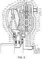
- FIG. 2 is a partial cross-sectional view illustrating the damper device 10.
- a starting device 1 shown in these drawings includes an engine EG (internal combustion engine) as a driving device, a transmission TM such as an automatic transmission (AT), a continuously variable transmission (CVT), and an output shaft OS of the transmission TM.
- Vehicle V including a differential gear DF connected directly to the vehicle or via a gear mechanism (not shown), a drive shaft DS connected to the differential gear DF (a pair of side gears), a drive wheel DW connected to the drive shaft DS, and the like. It is mounted on.
- the starting device 1 includes, in addition to the damper device 10, a front cover 3 as an input member connected to a crankshaft CS of the engine EG and transmitting torque from the engine EG, and a pump impeller fixed to the front cover 3. (Input-side fluid transmission element) 4, a turbine runner (output-side fluid transmission element) 5, which is disposed in a fluid chamber Cf defined by the front cover 3 and the pump impeller 4 so as to rotate coaxially with the pump impeller 4.
- axial direction basically indicates the direction in which the central axis (axis) of the starting device 1 and the damper device 10 extends, unless otherwise specified.
- the “radial direction” is basically the radial direction of the starting device 1, the damper device 10, and rotating elements such as the damper device 10, that is, the center of the starting device 1 and the damper device 10, unless otherwise specified.
- An extending direction of a straight line extending from the axis in a direction (radial direction) orthogonal to the center axis is shown.
- the “circumferential direction” basically corresponds to the circumferential direction of the starting device 1, the damper device 10, the rotating elements of the damper device 10, and the like, that is, the rotating direction of the rotating element, unless otherwise specified. Indicates the direction.
- the pump impeller 4 includes a pump shell 40 (not shown) tightly fixed to the front cover 3 and a plurality of pump blades 41 disposed on the inner surface of the pump shell 40.
- the turbine runner 5 includes a turbine shell 50 and a plurality of turbine blades 51 disposed on an inner surface of the turbine shell 50.
- the inner peripheral portion of the turbine shell 50 is fixed to the damper hub 7 via a plurality of rivets 70.
- the pump impeller 4 and the turbine runner 5 face each other, and a stator 6 is coaxially arranged between the two.
- the stator 6 includes a plurality of stator blades 60, and the rotation direction of the stator 6 is set to only one direction by a one-way clutch 61 (see FIG. 1).
- the pump impeller 4, the turbine runner 5, and the stator 6 form a torus (annular flow path) for circulating hydraulic oil, and function as a torque converter (fluid power transmission) having a torque amplification function.
- the stator 6 and the one-way clutch 61 may be omitted, and the pump impeller 4 and the turbine runner 5 may function as a fluid coupling.
- the lock-up clutch 8 is disposed in the fluid chamber Cf, performs lock-up for connecting the front cover 3 and the damper hub 7 via the damper device 10, and releases the lock-up.
- the lock-up clutch 8 may be a hydraulic single-plate clutch including a lock-up piston 80 to which a friction material 81 is attached, as shown in the figure, and at least one friction engagement plate (a plurality of friction materials). May be used.
- the damper device 10 is disposed in the fluid chamber Cf, and as shown in FIGS. 1 and 2, a drive plate (input element) 11, an intermediate member (intermediate element) 12, and a driven member (output) as rotating elements. Element) 15. Further, the damper device 10 includes, as a torque transmitting element (torque transmitting elastic body), a plurality of (for example, three) first springs (for example, three) that transmit torque between the drive plate 11 and the intermediate member 12. (1 elastic body) SP1 and a plurality of (for example, three in the present embodiment) second springs that act in series with the corresponding first springs SP1 to transmit torque between the intermediate member 12 and the driven member 15. (Second elastic body) SP2 and a plurality of (for example, three in this embodiment) third springs SP3 that transmit torque between the drive plate 11 and the driven member 15 are included.
- a torque transmitting elastic body a plurality of (for example, three) first springs (for example, three) that transmit torque between the drive plate 11
- the first and second springs SP1 and SP2 and the third spring SP3 are linear types made of a metal material spirally wound so as to have an axis extending straight when no load is applied.
- a coil spring is employed.
- the first and second springs SP1 and SP2 and the third spring SP3 can be more appropriately extended and contracted along the axis as compared with the case where the arc coil spring is used.
- the relative displacement between the drive plate 11 (input element) and the driven member 15 (output element) increases, the torque transmitted to the driven member 15 from the second spring SP2 and the like, the drive plate 11 and the driven
- the difference from the torque transmitted from the second spring SP2 or the like to the driven member 15, that is, the hysteresis can be reduced.
- an arc coil spring may be employed as at least one of the first and second springs SP1 and SP2 and the third spring SP3.
- the spring constants of the first and second springs SP1 and SP2 may be the same or different from each other.
- the combined spring constant of the plurality of first springs SP1 and the plurality of second springs SP2 is a value within a range from 600 Nm / rad to 1000 Nm / rad.
- the drive plate (input plate) 11 of the damper device 10 is a single annular plate (pressed product) formed by pressing a metal plate. Is connected to a lock-up piston 80 of the lock-up clutch 8.
- the drive plate 11 includes a plurality of (for example, three in the present embodiment) inner spring receiving windows 11wi extending in an arc shape and a plurality (for example, three in the present embodiment) of inner spring contact portions 11ci.
- a plurality of (for example, three in this embodiment) outer spring accommodation windows 11wo each extending in an arc shape, and a plurality (for example, six in this embodiment) of outer spring contact portions 11co are included.
- the plurality of inner spring receiving windows 11wi are respectively opened on the inner peripheral side of the drive plate 11, and are arranged at equal intervals in the drive plate 11 in the circumferential direction.
- the inner spring contact portions 11ci are formed one by one in the circumferential direction of the adjacent inner spring housing windows 11wi.
- the plurality of outer spring receiving windows 11wo each have a circumferential length corresponding to the natural length of the third spring SP3, and are disposed radially outside the inner spring receiving window 11wi at equal intervals (at equal intervals) in the circumferential direction. Is done.
- One outer spring contact portion 11co is formed on each side of each outer spring housing window 11wo in the circumferential direction.
- the intermediate member 12 is a single annular plate (pressed product) formed by pressing a metal plate, and is rotatably supported by the driven member 15.
- the intermediate member 12 includes a plurality (for example, three in the present embodiment) of spring contact portions (not shown) projecting radially outward from the outer peripheral surface at intervals (equal intervals) in the circumferential direction.
- the driven member 15 has a first output plate 16 fixed to the damper hub 7 together with the turbine shell 50 of the turbine runner 5 via the plurality of rivets 70, and has an inner diameter larger than the first output plate 16 and And a second output plate 17 arranged to be separated from the second output plate 17.
- the first and second output plates 16 and 17 are annular plates (pressed products) formed by pressing a metal plate.
- the first output plate 16 includes a plurality of (for example, three in the present embodiment) inner spring housing windows 16wi extending in an arc shape and a plurality of (for example, three in the present embodiment) windows.
- the plurality of inner spring receiving windows 16wi are arranged on the first output plate 16 at equal intervals in the circumferential direction (at equal intervals), and the inner spring contact portions 16ci are arranged in the circumferential direction of the adjacent inner spring receiving windows 16wi.
- the plurality of outer spring receiving windows 16wo each have a circumferential length longer than the natural length of the third spring SP3, and are disposed radially outside the inner spring receiving windows 16wi at equal intervals (at equal intervals). Is done.
- One outer spring contact portion 16co is formed on each side of each outer spring housing window 16wo in the circumferential direction.
- the first output plate 16 has a plurality of (for example, three in this embodiment) spring support portions 161 extending along the inner peripheral edge of each inner spring receiving window 16wi, and an outer peripheral edge of each inner spring receiving window 16wi.
- a plurality (for example, three in the present embodiment) of spring support portions 164 extending along the outer peripheral edge of each outer spring housing window 16wo.
- the second output plate 17 includes a plurality of (for example, three in the present embodiment) inner spring housing windows 17wi extending in an arc shape, and a plurality (for example, three in the present embodiment).
- the plurality of inner spring accommodating windows 17wi are arranged at equal intervals in the circumferential direction on the second output plate 17, and the inner spring contact portions 17ci are arranged in the circumferential direction of the adjacent inner spring accommodating windows 17wi. One is formed between them.
- the plurality of outer spring receiving windows 17wo each have a circumferential length longer than the natural length of the third spring SP3, and are arranged at equal intervals in the radial direction outside the inner spring receiving window 17wi in the radial direction. Is done.
- One outer spring contact portion 17co is formed on each side in the circumferential direction of each outer spring housing window 17wo.
- the second output plate 17 includes a plurality (for example, three in this embodiment) of spring support portions 171 extending along the inner peripheral edge of each inner spring receiving window 17wi, and an outer peripheral edge of each inner spring receiving window 17wi.
- a plurality (for example, three in the present embodiment) of spring support portions 174 extending along the outer peripheral edge of each outer spring housing window 17wo.
- the first and second output plates 16 and 17 face each other along the axial direction of the damper device 10, and a plurality of rivets (not shown) sandwich the drive plate 11 and the intermediate member 12.
- the drive plate 11 is disposed in the outer peripheral region between the first and second output plates 16 and 17 in the axial direction.
- the intermediate member 12 has an inner peripheral side region between the first and second output plates 16 and 17 in the axial direction such that each spring contact portion is located in the corresponding inner spring receiving window 11wi of the drive plate 11. That is, it is arranged radially inward of the drive plate 11.
- the inner peripheral surface of the intermediate member 12 is rotatably supported by a support portion 17 s extending in the axial direction from the inner peripheral portion of the second output plate 17.
- the first and second springs SP1 and SP2 are arranged in the inner spring receiving window 11wi of the drive plate 11 so as to be alternately arranged along the circumferential direction of the damper device 10, and the first and second output plates 16 and SP2 are also arranged. 17 supported. That is, the first and second springs SP1 and SP2 are arranged one by one in the inner spring receiving windows 11wi, 16wi and 17wi arranged in the axial direction of the damper device 10 so as to make a pair (act in series). You. Further, the first and second springs SP1 and SP2 in each inner spring housing window 11wi are supported (guided) from the radial inner side by the corresponding spring support portions 161 and 171 of the first and second output plates 16 and 17. You. Further, the first and second springs SP1 and SP2 in each inner spring accommodation window 11wi are supported (guided) from the radial outside by the corresponding spring support portions 162 and 172 of the first and second output plates 16 and 17. You.
- first and second springs SP1 and SP2 which are arranged within 11wi and do not form a pair (do not act in series), abut against both ends. That is, in the mounted state of the damper device 10, one end of each first spring SP1 and the other end of each second spring SP2 abut on the corresponding inner spring abutting portion 11ci of the drive plate 11.
- the spring contact portions of the intermediate member 12 are arranged in the common inner spring receiving windows 11wi, 16wi and 17wi, and form the first and second springs SP1 and SP2 forming a pair with each other. Between both ends. That is, the other end of each first spring SP1 and one end of each second spring SP2 abut on the corresponding spring abutment of the intermediate member 12.
- the inner spring contact portions 16ci and 17ci of the first and second output plates 16 and 17 (the driven member 15) facing each other do not form a pair (as in the case of the inner spring contact portion 11ci of the drive plate 11).
- the first and second springs SP1 and SP2 are in contact with both ends. Thereby, in the mounted state of the damper device 10, the one end of each first spring SP1 also comes into contact with the corresponding inner spring contact portion 16ci, 17ci of the driven member 15, and the other end of each second spring SP2. Also contact the corresponding inner spring contact portions 16ci and 17ci of the driven member 15.
- the driven member 15 is connected to the drive plate 11 via the plurality of first springs SP1, the intermediate member 12, and the plurality of second springs SP2, and the paired first and second springs SP1 and SP1.
- the SP2 is connected in series between the drive plate 11 and the driven member 15 via an intermediate member 12 (spring abutting portion).
- each of the plurality of first and second springs SP1 and SP2 is arranged on the same circumference, and the axis of the starting device 1 and the damper device 10 and the axis of each of the first springs SP1. The distance is equal to the distance between the axis of the starting device 1 and the axis of each second spring SP2.
- Each third spring SP3 is disposed (fitted) in the corresponding outer spring receiving window 11wo of the drive plate 11 and supported by the first and second output plates 16 and 17. That is, in the mounted state of the damper device 10, both ends of each third spring SP3 abut on the corresponding outer spring abutting portion 11co of the drive plate 11, and each third spring SP3 is connected to the first and second output plates.
- the outer spring housing windows 16 wo and 17 wo corresponding to the outer spring housing windows 16 and 17 are located near central portions in the circumferential direction. Further, the third spring SP3 in each outer spring accommodation window 11wo is supported (guided) from the radially inner side by the corresponding spring support portions 163, 173 of the first and second output plates 16, 17.
- each third spring SP3 in each outer spring housing window 11wo is supported (guided) from the radial outside by the corresponding spring support portions 164, 174 of the first and second output plates 16, 17.
- each third spring SP3 is disposed radially outward from the first and second springs SP1 and SP2 so as to overlap the first and second springs SP1 and SP2 as viewed from the radial direction. This makes it possible to further reduce the axial length of the damper device 10 and thus the starting device 1.
- each third spring SP3 In a state where the damper device 10 is mounted, between each third spring SP3 and the outer spring contact portions 16co, 17co of the first and second output plates 16, 17 (driven member 15) located on both sides thereof. A predetermined circumferential interval is formed, and the two do not abut.
- One of the outer spring contact portions 16co and 17co located on both sides of each third spring SP3 is connected to the drive plate 11 and the driven member 15 when torque is transmitted between the drive plate 11 and the driven member 15. As the relative torsion angle of No. 15 increases, it comes into contact with one end of the third spring SP3.
- the circumferential distance between the end of the third spring SP3 and the outer spring contact portions 16co, 17co of the driven member 15 in the mounted state of the damper device 10 is transmitted from the engine EG to the drive plate 11.
- the input torque reaches a predetermined torque (first value) T1 smaller than the torque T2 (second value) corresponding to the maximum torsion angle ⁇ max of the damper device 10
- the main rotation of the drive plate 11 and the like is started.
- One end of the third spring SP3 located on the front side in the direction (rotation direction when the vehicle is moving forward (engine EG)) is determined such that one end of the third spring SP3 comes into contact with the front outer spring contact portions 16co and 17co in the main rotation direction.
- the damper device 10 also includes a stopper 18 (see FIG. 1) for restricting the relative rotation between the drive plate 11 and the driven member 15.
- the stopper 18 is configured to regulate the relative rotation between the drive plate 11 and the driven member 15 when the input torque to the drive plate 11 reaches the torque T2 corresponding to the maximum torsion angle ⁇ max. .
- the first and second springs SP1 and SP2 act in series until the input torque to the drive plate 11 reaches the torque T1.
- the third spring SP3 acts in parallel with the first and second springs SP1 and SP2 acting in series. Therefore, the damper device 10 has a two-stage (two-stage) damping characteristic.
- the damper device 10 includes a mass body 19 fixed to the damper hub 7 so as to be located between the turbine runner 5 and the first output plate 16 of the damper device 10 in the axial direction.
- the mass body 19 includes an annular first plate 191 having a larger diameter than the turbine runner 5, and an annular second plate 192 having an inner diameter larger than the inner diameter of the first plate 191.
- the inner peripheral portion of the first plate 191 is fixed to the damper hub 7 together with the turbine shell 50 of the turbine runner 5 and the first output plate 16 via the plurality of rivets 70.
- the outer peripheral portion 191o of the first plate 191 is bent toward the turbine runner 5, and at least one balance weight 193 is fixed to the outer peripheral portion 191o as necessary.
- the second plate 192 is fixed to the first plate 191 via a plurality of rivets so as not to interfere with the first output plate 16 (spring support 162) and the like.
- the torque (power) transmitted from the engine EG to the front cover 3 is applied to the pump.
- the power is transmitted to the input shaft IS of the transmission TM via the path of the impeller 4, the turbine runner 5, the driven member 15, and the damper hub 7, and further transmitted to the drive wheels DW via the differential gear DF and the drive shaft DS.
- the lock-up clutch 8 of the starting device when the lock-up is performed by the lock-up clutch 8 of the starting device 1, the torque transmitted from the engine EG to the drive plate 11 via the front cover 3 and the lock-up clutch 8 is transmitted to the drive plate 11.
- each third spring SP3 causes the rear outer spring contact portion 11co of the drive plate 11 in the main rotation direction and the driven member 15 (the first and second output plates 16, 17) in the main rotation direction. While expanding and contracting between the front outer spring contact portions 16co and 17co, the torque acts between the drive plate 11 and the intermediate member 12 in parallel with the first and second springs SP1 and SP2 acting in series. introduce.
- the first to third springs SP1, SP2, SP3 can absorb large torque fluctuations transmitted to the drive plate 11.
- the lock-up rotation speed Nlup engagement rotation speed of the lock-up clutch 8 to which the engine EG and the damper device 10 are first connected after the engine EG is started is reduced to a low rotation at which the lock-up is not performed.
- Lock-up rotation is set by setting the rotation speed range where any resonance that occurs in the range converges. It is possible to reduce further the number Nlup.
- the present inventors have conducted intensive studies in order to further improve the vibration damping performance of the damper device 10, as a result, the moment of inertia J 2, transmission differential gear from the input shaft IS of the TM DF ( focusing on the relationship between the total moment of inertia J TM of all rotating members included until the pair of side gears) connected to the drive shaft DS.
- Moment of inertia J TM includes a full rotation member of the transmission TM, such input shaft IS and the various shaft such or gear of the output shaft OS and the like, is the sum of the inertia moment of the whole rotary member of the differential gear DF, a output shaft OS
- a gear mechanism or the like is included between the gear mechanism and the differential gear DF, the moment of inertia of all rotating members of the gear mechanism is also included.
- the present inventors have determined the appropriate range of the sum (J 2 + J TM) ratio of moment of inertia J 2 for J 2 / (J 2 + J TM) and the moment of inertia J 2 and moment of inertia J TM.
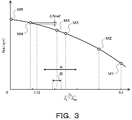
- the present inventors have prepared a plurality of models of damper devices having different ratios J 2 / (J 2 + J TM ), and provided a lock for which engagement of the lock-up clutch 8 is permitted for each model.
- the allowable rotation speed Na was determined by analysis, and a characteristic curve of FIG. 3 showing the relationship between the ratio J 2 / (J 2 + J TM ) and the lockup allowable rotation speed Na was obtained.
- FIG. 4 shows the relationship between the rotation speed Ne of the engine EG and the torque fluctuation T Fluc of the driven member 15 in the models M1 to M5.
- a dashed line indicates a target lock-up rotation speed Nlup (the left side ( ⁇ side) of the dashed line in the figure corresponds to an allowable range)
- a two-dot chain line indicates an allowable level of resonance ( The lower side ( ⁇ side) of the two-dot chain line in the figure corresponds to the allowable range.)
- the ratio J 2 / (J 2 + J TM) increases, the lock-up permissible rotational speed Na is reduced.
- the resonance see the resonance R1 in FIG. 3 following the resonance (see resonance R1 in FIG. 3) that occurs in a low rotation range where lockup is not performed.
- the characteristic curve of FIG. 1 The lower limit of the ratio J 2 / (J 2 + J TM ) was set to 0.12.
- the damper device 10 of the present disclosure the sum of the moment of inertia J 2 and moment of inertia J TM (J 2 + J TM ) ratio J 2 / moment of inertia J 2 for (J 2 + J TM) is 0. It is designed to satisfy 12 ⁇ J 2 / (J 2 + J TM ) ⁇ 0.5.
- the damper device 10 while suppressing the increase in cost due to the addition of the second intermediate member and the spring, while suppressing the decrease in the vibration damping performance in the low rotation region near the lock-up rotation speed Nup, the lock-up rotation is suppressed. It is possible to reduce the number Nlup. Further, as a result of the study by the present inventors, the moment of inertia J 2 , J TM is 0.15 ⁇ J 2 / (J 2 + J TM ) ⁇ 0.3 (range A in FIG. 3), more preferably 0. When 19 ⁇ J 2 / (J 2 + J TM ) ⁇ 0.23 (range B in FIG. 3) is satisfied, suppression of a decrease in vibration damping performance in a low rotation range and securing of a decrease in lock-up rotation speed Nlup. It has been found that both can be balanced.
- the damper device 10 includes one drive plate 11 as an input element, and has a first and a second output plate 16 that face each other along the axial direction and are connected to each other so as to sandwich the drive plate 11. 17 as an output element.
- the thickness of at least one of the first and second output plates 16 and 17 may be greater than the thickness of the drive plate 11.
- the thickness of the straight portion extending in the radial direction of at least one of the first and second output plates 16 and 17 may be equal to or greater than the thickness of the straight portion of the drive plate 11.
- 17 may be greater than the thickness of the base material of the drive plate 11.
- one of the first and second output plates 16 and 17 connected to the damper hub 7, that is, the thickness of the first output plate 16 may be greater than the thickness of the drive plate 11.
- the driven member 15 of the damper device 10 may be connected to a mass body 19B as shown in FIG.
- the mass body 19B shown in FIG. 5 includes only one annular plate member 195.
- the base material of the plate member 195 has an outer diameter sufficiently larger than the outer diameter of the turbine runner 5, and the outer peripheral portion of the base material is subjected to flow forming, so that the outer peripheral portion of the plate member 195 is widened.
- a portion 196 is formed.
- both the turbine runner 5 and the mass body 19 are connected to the driven member 15, which is an output element, but the invention is not limited to this. That is, connection of at least one of the turbine runner 5 and the mass body 19 to the driven member 15 may be omitted.
- the third spring SP3 is connected in parallel with one of the first and second springs SP1 and SP2. It may be configured to work. Further, the third spring SP3 may be omitted from the damper device 10.
- the configuration of the present disclosure includes a drive member (input element) 11B and a driven member (output element) 15B as rotating elements, and a plurality of torque transmission elements disposed between the drive member 11B and the driven member 15B.
- a damper device 10B that includes a spring (elastic body) SP (and a plurality of springs SP3) and does not include an intermediate element (see FIG. 6).
- the combined spring constant of the plurality of springs SP arranged between the drive member 11B and the driven member 15B is a value within a range from 1400 Nm / rad to 1800 Nm / rad.
- the output element (and the member that rotates integrally with the output element) and the entire rotating member from the input shaft of the transmission to the drive shaft are reversed.
- the moment of inertia J 2 in the damper device 10B is increased by about 7-8% than the moment of inertia J 2 in the damper device 10.
- the lower limit of the ratio J 2 / (J 2 + J TM) similarly to the damper device 10 can be 0.12.
- the damper device 10B defines the value of the moment of inertia J 2 as percentage J 2 / (J 2 + J TM) satisfies 0.12 ⁇ J 2 / (J 2 + J TM) ⁇ 0.55 Good.
- the lockup rotation speed Nlup is suppressed while suppressing the increase in cost due to the addition of the intermediate member and the spring body, while suppressing the decrease in the vibration damping performance in the low rotation range near the lockup rotation speed Nlup. Can be reduced.
- the moments of inertia J 2 and J TM are 0.15 ⁇ J 2 / (J 2 + J TM ) ⁇ 0.3, more preferably 0.19 ⁇ J 2 / (J 2 + J).
- the configuration of the present disclosure includes an input element, a first intermediate element, a second intermediate member, and an output element as rotating elements, and is disposed between the input element and the first intermediate element as torque transmitting elements.
- Damper device including a first elastic member, a second elastic member disposed between the first intermediate element and the second intermediate element, and a third elastic member disposed between the second intermediate element and the output element. May be applied.
- the configuration of the present disclosure may be applied to a damper device including two torque transmission paths provided in parallel between an input element and an output element.
- the input element of the damper device 10 may include at least one drive plate 11, and may be connected to the drive plate 11 such as a second plate member or a clutch drum of a hydraulic multi-plate clutch. Other members may be included.
- the damper device includes the input element (11) connected to the engine (EG) via the clutch (8), the intermediate element (12), and the input shaft of the transmission (TM). (IS), an output element (15), a first elastic body (SP1) disposed between the input element (11) and the intermediate element (12), and the intermediate element (12).
- rotary element (5,7,19,19B, 70) that rotates integrally with the output element (15) in the engine (EG) side of the input shaft (iS) the total moment of inertia of the set to J 2 And the output of the transmission (TM) from the input shaft (IS) The total moment of inertia of all rotating members included until a differential gear (DF) when the J TM which is connected to a shaft (OS), 0.12 ⁇ J 2 / (J 2 + J TM ) ⁇ 0.5 It satisfies.
- DF differential gear
- the present inventors have conducted intensive studies to improve the vibration damping performance of the damper device including the input element, the intermediate element, the output element, and the first and second elastic bodies.
- the output element of the damper device and the transmission total moment of inertia of all rotating members included between the total moment of inertia J 2 of the rotating element which rotates together with the output element in the engine side of the input shaft to a differential gear from the input shaft of the transmission focusing on the relationship between J TM.
- the present inventors have found that the moment of inertia J 2 and moment of inertia J sum of the TM ratio of moment of inertia J 2 for (J 2 + J TM) J 2 / (J 2 + J TM) is 0.12 ⁇ J 2 /
- the damper device so as to satisfy (J 2 + J TM ) ⁇ 0.5, it is possible to suppress a decrease in the vibration damping performance of the damper device due to resonance on a higher frequency side than the engagement rotation speed of the clutch, and to reduce the engagement rotation speed. It has been found that the resonance on the lower frequency side than the number can be shifted to the lower frequency side.
- the engine and the damper device are connected while suppressing a cost increase due to the addition of the second intermediate element and the elastic body, and suppressing a decrease in vibration damping performance in a low rotation range. It is possible to reduce the rotational speed of the clutch.
- the damper device (10) of the present disclosure may satisfy 0.15 ⁇ J 2 / (J 2 + J TM ) ⁇ 0.3, and may satisfy 0.19 ⁇ J 2 / (J 2 + J TM). ) ⁇ 0.23. As a result, it is possible to balance the suppression of the decrease in the vibration damping performance in the low rotational speed region and the securing of the amount of decrease in the clutch rotational speed in a well-balanced manner.
- the rotating element that rotates integrally with the output element (15) is connected to the output element (15) and is fixed to the input shaft (IS) of the transmission (TM). And a mass (19, 19B) coupled to the output element (15).
- the damper device (10) may be arranged in the fluid chamber (Cf) of the starting device (1) including the pump impeller (4) and the turbine runner (5), and is integrated with the output element (15).
- the rotating element rotating in the direction of rotation may include the turbine runner (5) connected to the output element (15).
- the input element may include one input plate (11), and the output element (15) faces each other along the axial direction of the damper device (10), and includes the input plate (11). ) May be included so as to sandwich the two output plates (16, 17). This allows for greater moment of inertia and hence the moment of inertia J 2 output elements.
- the intermediate element (12) may be disposed between the two output plates (16, 17) in the axial direction.
- the damper device (10) is held by the output element (15) when torque is not transmitted between at least the input element (11) and the output element (15), and the input element (15) When torque is transmitted between the element (11) and the output element (15), the torque increases as the relative twist angle between the input element (11) and the output element (15) increases.
- a third elastic body (SP3) acting in parallel with at least one of the first and second elastic bodies (SP1, SP2) may be included.
- a combined spring constant of the first and second elastic bodies may be 600 to 1000 Nm / rad.
- the design method of the damper device includes an input element (11) connected to an engine (EG) via a clutch (8), an intermediate element (12), and an input shaft (IS) of a transmission (TM).
- rotary element (5,7,19,19B, 70) that rotates integrally with the output element (15) in the engine (EG) side of the input shaft (iS) the total moment of inertia of the set to J 2 And the output of the transmission (TM) from the input shaft (IS)
- Another damper device of the present disclosure includes an input element (11B) connected to an engine (EG) via a clutch (8) and an output element (15B) connected to an input shaft (IS) of a transmission (TM). ) And a plurality of elastic bodies (SP) disposed between the input element (11B) and the output element (15B), the output element (15B) and the input axis and the output element by the engine (EG) side of (iS) and (15B) the total moment of inertia of the rotating element which rotates together with the J 2, the transmission from the input shaft (iS) (TM) the total moment of inertia of all rotating members included until a differential gear (DF) coupled to the output shaft (OS) when the J TM, 0.12 ⁇ J 2 / (J 2 + J TM ) ⁇ 0.55 It satisfies.
- SP elastic bodies
- the present inventors have conducted intensive studies to improve the vibration damping performance of a damper device including an input element, an output element, and a plurality of elastic bodies disposed therebetween, and as a result, the damper device has an inertia.
- moment J 2 and the sum of the moment of inertia J TM (J 2 + J TM ) ratio of moment of inertia J 2 for J 2 / (J 2 + J TM) is 0.12 ⁇ J 2 / (J 2 + J TM) ⁇ 0. 55, while suppressing the reduction of the vibration damping performance of the damper device due to the resonance on the higher frequency side than the engagement rotation speed of the clutch, the resonance on the lower frequency side than the engagement rotation speed is reduced to a lower frequency.
- another damper device (10B) of the present disclosure may satisfy 0.15 ⁇ J 2 / (J 2 + JTM ) ⁇ 0.3, and may satisfy 0.19 ⁇ J 2 / (J 2 + J TM ) ⁇ 0.23.
- the composite spring constant of the plurality of elastic bodies (SP) may be 1400-1800 Nm / rad.
- Another design method of the damper device of the present disclosure includes an input element (11B) connected to an engine (EG) via a clutch (8) and an output connected to an input shaft (IS) of a transmission (TM).
- a damper device (10B) including an element (15B) and a plurality of elastic bodies (SP) disposed between the input element (11B) and the output element (15B), and 15B), the total moment of inertia of the rotating element that rotates integrally with the output element (15B) in the engine (EG) side of the input shaft (iS) and J 2, from the input shaft (iS) the total moment of inertia of all rotating members included until differential gear connected to an output shaft (OS) of the transmission (TM) (DF) when the J TM, 0.12 ⁇ J 2 / (J 2 + J TM ) ⁇ 0.55 It is intended to define the moment of inertia J 2 so as to satisfy.
- the invention of the present disclosure can be used in the field of manufacturing a damper device and the like.
Landscapes
- Engineering & Computer Science (AREA)
- General Engineering & Computer Science (AREA)
- Mechanical Engineering (AREA)
- Physics & Mathematics (AREA)
- Acoustics & Sound (AREA)
- Aviation & Aerospace Engineering (AREA)
- Chemical & Material Sciences (AREA)
- Combustion & Propulsion (AREA)
- Mechanical Operated Clutches (AREA)
Abstract
La présente invention concerne un dispositif amortisseur comprenant : un élément d'entrée connecté à un moteur par l'intermédiaire d'un embrayage ; un élément intermédiaire ; un élément de sortie connecté à un arbre d'entrée d'une transmission ; un premier corps élastique disposé entre l'élément d'entrée et l'élément intermédiaire ; et un second corps élastique qui est disposé entre l'élément intermédiaire et l'élément de sortie et qui agit en série avec le premier corps élastique, lorsque J2 est le moment d'inertie total de l'élément de sortie et un élément rotatif tournant d'un seul tenant avec l'élément de sortie et plus proche du moteur que l'arbre d'entrée et JTM est le moment d'inertie total de tous les éléments rotatifs entre l'arbre d'entrée et un engrenage différentiel connecté à l'arbre de sortie de la transmission, la relation 0,12 ≤ J2/(J2 + JTM) ≤ 0,5 étant satisfaite.
Priority Applications (2)
| Application Number | Priority Date | Filing Date | Title |
|---|---|---|---|
| US17/266,658 US11867239B2 (en) | 2018-09-20 | 2019-09-12 | Damper device and design method of damper device |
| CN201980054588.XA CN112585377B (zh) | 2018-09-20 | 2019-09-12 | 减振装置及其设计方法 |
Applications Claiming Priority (2)
| Application Number | Priority Date | Filing Date | Title |
|---|---|---|---|
| JP2018-176504 | 2018-09-20 | ||
| JP2018176504 | 2018-09-20 |
Publications (1)
| Publication Number | Publication Date |
|---|---|
| WO2020059632A1 true WO2020059632A1 (fr) | 2020-03-26 |
Family
ID=69888497
Family Applications (1)
| Application Number | Title | Priority Date | Filing Date |
|---|---|---|---|
| PCT/JP2019/035931 Ceased WO2020059632A1 (fr) | 2018-09-20 | 2019-09-12 | Dispositif amortisseur et procédé de conception associé |
Country Status (3)
| Country | Link |
|---|---|
| US (1) | US11867239B2 (fr) |
| CN (1) | CN112585377B (fr) |
| WO (1) | WO2020059632A1 (fr) |
Families Citing this family (1)
| Publication number | Priority date | Publication date | Assignee | Title |
|---|---|---|---|---|
| JP7624863B2 (ja) * | 2021-04-01 | 2025-01-31 | 株式会社エクセディ | 流体継手 |
Citations (4)
| Publication number | Priority date | Publication date | Assignee | Title |
|---|---|---|---|---|
| JPS62126624U (fr) * | 1986-02-04 | 1987-08-11 | ||
| JPH04151056A (ja) * | 1990-10-11 | 1992-05-25 | Toyota Motor Corp | 直結クラッチ付流体伝動装置 |
| JP2012184840A (ja) * | 2011-02-15 | 2012-09-27 | Aisin Aw Co Ltd | ダンパ装置 |
| JP2018132159A (ja) * | 2017-02-17 | 2018-08-23 | 株式会社エクセディ | トルク変動抑制装置、トルクコンバータ、及び動力伝達装置 |
Family Cites Families (6)
| Publication number | Priority date | Publication date | Assignee | Title |
|---|---|---|---|---|
| US5617940A (en) * | 1994-02-08 | 1997-04-08 | Exedy Corporation | Power transfer apparatus having a vibration dampening mechanism which provides structural support for the apparatus |
| JP2004278744A (ja) * | 2003-03-18 | 2004-10-07 | Exedy Corp | ダンパー機構及びダンパーディスク組立体 |
| JP6090466B2 (ja) * | 2013-09-30 | 2017-03-08 | アイシン・エィ・ダブリュ株式会社 | ダンパ装置および発進装置 |
| JP6250841B2 (ja) * | 2014-12-25 | 2017-12-20 | アイシン・エィ・ダブリュ工業株式会社 | ダンパ装置 |
| JP6361617B2 (ja) * | 2015-09-14 | 2018-07-25 | トヨタ自動車株式会社 | 捩り振動低減装置 |
| JP6605280B2 (ja) * | 2015-09-30 | 2019-11-13 | アイシン・エィ・ダブリュ株式会社 | ダンパ装置 |
-
2019
- 2019-09-12 CN CN201980054588.XA patent/CN112585377B/zh active Active
- 2019-09-12 WO PCT/JP2019/035931 patent/WO2020059632A1/fr not_active Ceased
- 2019-09-12 US US17/266,658 patent/US11867239B2/en active Active
Patent Citations (4)
| Publication number | Priority date | Publication date | Assignee | Title |
|---|---|---|---|---|
| JPS62126624U (fr) * | 1986-02-04 | 1987-08-11 | ||
| JPH04151056A (ja) * | 1990-10-11 | 1992-05-25 | Toyota Motor Corp | 直結クラッチ付流体伝動装置 |
| JP2012184840A (ja) * | 2011-02-15 | 2012-09-27 | Aisin Aw Co Ltd | ダンパ装置 |
| JP2018132159A (ja) * | 2017-02-17 | 2018-08-23 | 株式会社エクセディ | トルク変動抑制装置、トルクコンバータ、及び動力伝達装置 |
Also Published As
| Publication number | Publication date |
|---|---|
| CN112585377A (zh) | 2021-03-30 |
| CN112585377B (zh) | 2022-05-13 |
| US20210364047A1 (en) | 2021-11-25 |
| US11867239B2 (en) | 2024-01-09 |
Similar Documents
| Publication | Publication Date | Title |
|---|---|---|
| JP6609029B2 (ja) | ダンパ装置 | |
| CN103038545B (zh) | 流体传动装置 | |
| JP6781791B2 (ja) | ダンパ装置 | |
| JP6479182B2 (ja) | ダンパ装置 | |
| TWI657207B (zh) | 扭轉振動衰減裝置 | |
| JP6090466B2 (ja) | ダンパ装置および発進装置 | |
| CN103038544A (zh) | 流体传动装置 | |
| JP6609028B2 (ja) | ダンパ装置 | |
| JP6426287B2 (ja) | ダンパ装置 | |
| JP6458722B2 (ja) | ダンパ装置 | |
| JP6409874B2 (ja) | 発進装置 | |
| WO2020059632A1 (fr) | Dispositif amortisseur et procédé de conception associé | |
| JP2019056461A (ja) | ダンパ装置 | |
| JP7393993B2 (ja) | ダンパ装置および発進装置 | |
| JP6477154B2 (ja) | ダンパ装置 | |
| JP2021143686A (ja) | 回転慣性質量ダンパおよびその製造方法 |
Legal Events
| Date | Code | Title | Description |
|---|---|---|---|
| 121 | Ep: the epo has been informed by wipo that ep was designated in this application |
Ref document number: 19862109 Country of ref document: EP Kind code of ref document: A1 |
|
| NENP | Non-entry into the national phase |
Ref country code: DE |
|
| 122 | Ep: pct application non-entry in european phase |
Ref document number: 19862109 Country of ref document: EP Kind code of ref document: A1 |
|
| NENP | Non-entry into the national phase |
Ref country code: JP |