WO2020059638A1 - Plaque vibrante pour haut-parleurs - Google Patents
Plaque vibrante pour haut-parleurs Download PDFInfo
- Publication number
- WO2020059638A1 WO2020059638A1 PCT/JP2019/035952 JP2019035952W WO2020059638A1 WO 2020059638 A1 WO2020059638 A1 WO 2020059638A1 JP 2019035952 W JP2019035952 W JP 2019035952W WO 2020059638 A1 WO2020059638 A1 WO 2020059638A1
- Authority
- WO
- WIPO (PCT)
- Prior art keywords
- cone portion
- diaphragm
- joined
- speaker diaphragm
- ring member
- Prior art date
- Legal status (The legal status is an assumption and is not a legal conclusion. Google has not performed a legal analysis and makes no representation as to the accuracy of the status listed.)
- Ceased
Links
Images


Classifications
-
- H—ELECTRICITY
- H04—ELECTRIC COMMUNICATION TECHNIQUE
- H04R—LOUDSPEAKERS, MICROPHONES, GRAMOPHONE PICK-UPS OR LIKE ACOUSTIC ELECTROMECHANICAL TRANSDUCERS; ELECTRIC HEARING AIDS; PUBLIC ADDRESS SYSTEMS
- H04R1/00—Details of transducers, loudspeakers or microphones
- H04R1/10—Earpieces; Attachments therefor ; Earphones; Monophonic headphones
- H04R1/1058—Manufacture or assembly
- H04R1/1075—Mountings of transducers in earphones or headphones
-
- H—ELECTRICITY
- H04—ELECTRIC COMMUNICATION TECHNIQUE
- H04R—LOUDSPEAKERS, MICROPHONES, GRAMOPHONE PICK-UPS OR LIKE ACOUSTIC ELECTROMECHANICAL TRANSDUCERS; ELECTRIC HEARING AIDS; PUBLIC ADDRESS SYSTEMS
- H04R7/00—Diaphragms for electromechanical transducers; Cones
- H04R7/16—Mounting or tensioning of diaphragms or cones
- H04R7/18—Mounting or tensioning of diaphragms or cones at the periphery
- H04R7/22—Clamping rim of diaphragm or cone against seating
-
- H—ELECTRICITY
- H04—ELECTRIC COMMUNICATION TECHNIQUE
- H04R—LOUDSPEAKERS, MICROPHONES, GRAMOPHONE PICK-UPS OR LIKE ACOUSTIC ELECTROMECHANICAL TRANSDUCERS; ELECTRIC HEARING AIDS; PUBLIC ADDRESS SYSTEMS
- H04R7/00—Diaphragms for electromechanical transducers; Cones
- H04R7/02—Diaphragms for electromechanical transducers; Cones characterised by the construction
- H04R7/12—Non-planar diaphragms or cones
- H04R7/127—Non-planar diaphragms or cones dome-shaped
-
- H—ELECTRICITY
- H04—ELECTRIC COMMUNICATION TECHNIQUE
- H04R—LOUDSPEAKERS, MICROPHONES, GRAMOPHONE PICK-UPS OR LIKE ACOUSTIC ELECTROMECHANICAL TRANSDUCERS; ELECTRIC HEARING AIDS; PUBLIC ADDRESS SYSTEMS
- H04R7/00—Diaphragms for electromechanical transducers; Cones
- H04R7/16—Mounting or tensioning of diaphragms or cones
- H04R7/18—Mounting or tensioning of diaphragms or cones at the periphery
-
- H—ELECTRICITY
- H04—ELECTRIC COMMUNICATION TECHNIQUE
- H04R—LOUDSPEAKERS, MICROPHONES, GRAMOPHONE PICK-UPS OR LIKE ACOUSTIC ELECTROMECHANICAL TRANSDUCERS; ELECTRIC HEARING AIDS; PUBLIC ADDRESS SYSTEMS
- H04R9/00—Transducers of moving-coil, moving-strip, or moving-wire type
- H04R9/02—Details
- H04R9/04—Construction, mounting, or centering of coil
- H04R9/045—Mounting
-
- H—ELECTRICITY
- H04—ELECTRIC COMMUNICATION TECHNIQUE
- H04R—LOUDSPEAKERS, MICROPHONES, GRAMOPHONE PICK-UPS OR LIKE ACOUSTIC ELECTROMECHANICAL TRANSDUCERS; ELECTRIC HEARING AIDS; PUBLIC ADDRESS SYSTEMS
- H04R1/00—Details of transducers, loudspeakers or microphones
- H04R1/10—Earpieces; Attachments therefor ; Earphones; Monophonic headphones
-
- H—ELECTRICITY
- H04—ELECTRIC COMMUNICATION TECHNIQUE
- H04R—LOUDSPEAKERS, MICROPHONES, GRAMOPHONE PICK-UPS OR LIKE ACOUSTIC ELECTROMECHANICAL TRANSDUCERS; ELECTRIC HEARING AIDS; PUBLIC ADDRESS SYSTEMS
- H04R2307/00—Details of diaphragms or cones for electromechanical transducers, their suspension or their manufacture covered by H04R7/00 or H04R31/003, not provided for in any of its subgroups
- H04R2307/029—Diaphragms comprising fibres
-
- H—ELECTRICITY
- H04—ELECTRIC COMMUNICATION TECHNIQUE
- H04R—LOUDSPEAKERS, MICROPHONES, GRAMOPHONE PICK-UPS OR LIKE ACOUSTIC ELECTROMECHANICAL TRANSDUCERS; ELECTRIC HEARING AIDS; PUBLIC ADDRESS SYSTEMS
- H04R9/00—Transducers of moving-coil, moving-strip, or moving-wire type
- H04R9/06—Loudspeakers
Definitions
- the present disclosure relates to a speaker diaphragm suitable for use in headphones.
- the speaker used for the headphone is required to be small and thin in accordance with the requirements of the feeling of wearing and the design, and therefore the diaphragm used for the speaker is also required to be thin. For this reason, the rigidity of the dome-shaped diaphragm is reduced due to the restriction that the total height of the dome portion must be reduced.
- diaphragm materials such as synthetic polymers such as polyolefin and polyester, and those using new materials. Even today, there are many paper materials (cellulose) that are excellent in performance and cost. Used.
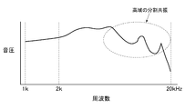
- the diaphragm when the speaker is made thinner, the diaphragm also becomes closer to a plane with the thinner speaker, and it becomes difficult to secure the rigidity of the diaphragm made mainly of cellulose in shape, and split resonance occurs in the diaphragm. . Due to the influence of the split resonance, as shown in FIG. 6, a peak or a dip (peak or valley) occurs in a high frequency range, which causes a problem that the sound pressure decreases and the frequency characteristics deteriorate.
- Patent Document 1 adopts a free edge structure in which a center cap portion and a cone portion are integrally formed.
- the thickness of the diaphragm is increased in order to improve the rigidity, the entire thickness of a single component as in Patent Literature 1 is increased, the mass is increased more than necessary, and the sound pressure is reduced. .
- Patent Document 2 employs a configuration in which a ring-shaped member as a separate component is provided on the outer periphery of the center cap portion. That is, the outer peripheral portion of the center cap portion is coupled to the inner peripheral portion of the ring-shaped member, and the edge portion is coupled to the outer peripheral portion of the ring-shaped member. There is a problem that alignment is difficult and the manufacturing process becomes complicated.
- Patent Document 3 also discloses a configuration in which a ring-shaped member is joined to the outer periphery of the center cap portion.
- the shape of the ring-shaped member is dome-shaped, and the thickness is at least twice the thickness of the center cap portion. To ensure that.
- the ring-shaped member In the case of Patent Document 3, the ring-shaped member must be formed in a dome shape or the thickness thereof must be increased, so that the production is complicated, and when the thickness is increased, the mass is increased and the sound pressure is increased. There is a problem that it decreases.
- Patent Document 4 adopts a configuration in which a reinforcing ring portion is joined to the inside of the outer peripheral portion of the center cap portion.
- a reinforcing ring portion In this diaphragm, a reinforcing ring portion must be formed and joined so as to conform to the shape of the inside of the curved outer peripheral portion of the dome-shaped center cap portion. Is also complicated.
- An embodiment of the present invention according to claim 2 is the speaker diaphragm according to claim 1, wherein the center cap portion has a dome shape, and the ring has the same shape as the cone portion on the front surface or the back surface of the cone portion. It is characterized by joining members.
- a diaphragm fixing ring is joined to an outer peripheral portion of the edge.
- An embodiment of the present invention according to claim 4 is the speaker diaphragm according to claim 1, wherein the body member and the ring member are formed by mixing biocellulose and carbon fiber with pulp. I do.
- the cone portion to which the ring member is joined has a rising shape facing forward.
- An embodiment of the present invention according to claim 6 is the speaker diaphragm according to claim 1, wherein the speaker diaphragm is for headphones.
- the rigidity of the cone portion is improved by joining the ring member to the cone portion without changing the shape of the body member including the center cap portion and the cone portion on the outer periphery thereof. Therefore, the thickness of the cone portion of the body member can be uniformly controlled in the circumferential direction, the rigidity can be improved even if the body member is thin and lightweight, and the entire body can be joined even if the ring member is joined to the cone portion. Can suppress a decrease in sound pressure and attenuation in a high frequency range.
- the rigidity of the outer peripheral portion of the body member that is, the cone portion
- the split resonance point can be shifted to a higher frequency, and a decrease in sound pressure in the higher frequency can be prevented, thereby improving the frequency characteristics. it can.
- the cone portion has a rising shape inclined toward the front surface (front of the speaker), positioning in the radial direction (centering) is easy, manufacturing is easy, and rigidity is improved if the rising shape is adopted.
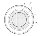
- FIG. 1 is an exploded perspective view of one embodiment of the present invention. It is an assembly perspective view same as the above. It is a top view same as the above. It is a half sectional view same as the above.
- FIG. 4 is an explanatory diagram of a frequency characteristic according to one embodiment of the present invention. It is an explanatory view of a conventional frequency characteristic.
- the main use of the speaker diaphragm of the embodiment of the present invention is intended for headphones, and the material is preferably a paper material, and it is assumed that the speaker diaphragm is a free edge type speaker diaphragm.
- reference numeral 1 denotes a body member of a diaphragm.
- the body member 1 includes a dome-shaped center cap portion 1a and a flange-shaped cone portion 1b formed to protrude radially outward at an outer peripheral edge thereof.
- Reference numeral 2 denotes a ring member.
- the ring member 2 has substantially the same shape as the cone portion 1b, and is bonded to the cone portion 1b via a hot-press using a urethane or rubber-based adhesive, joined and integrated.
- the ring member 2 is made of paper separately from the body member 1, is formed in a flat plate shape, and has a simple shape that is easy to manufacture.
- the rigidity of the cone portion 1b can be increased without changing the shape of the cone portion.
- a ring-shaped member it can be accurately bonded to the ring-shaped cone portion 1b of the body member 1, and the diaphragm can be configured uniformly in the circumferential direction.
- the entire body member 1 can be moved in the same phase by bonding the ring member 2 over the entire circumference of the cone portion 1b of the body member 1.
- the ring member 2 is bonded to the front surface of the cone portion 1b in FIG. 1, the bonding may be performed on either the front surface or the rear surface of the cone portion 1b.
- the ring member 2 and the body member 1 including the center cap portion 1a and the cone portion 1b are preferably made of the same material, for example, pulp (cellulose) such as wood pulp or non-wood pulp with biocellulose and carbon fiber reinforcement.
- pulp cellulose
- the rigidity of the material is improved by mixing a predetermined amount of the material.
- the reinforcing material is not limited to microfibers and carbon fibers, and other reinforcing materials can be used.
- the optimal blending ratio of pulp with biocellulose and carbon fiber as a reinforcing material is appropriately selected according to the use of the speaker diaphragm.
- reference numeral 3 denotes a ring-shaped and dome-shaped edge
- reference numeral 4 denotes a metal diaphragm fixing ring.
- the inner peripheral portion of the edge 3 is joined to the outer peripheral portion of the ring member 2 or the cone portion 1b via an adhesive, and the diaphragm fixing ring 4 is joined to the outer peripheral portion rear side of the edge 3 in the state shown in the drawing. May be joined to the front side.
- FIG. 2 is a perspective view of an assembled state
- FIG. 3 is a plan view.
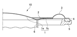
- FIG. 4 shows that a diaphragm fixing ring 4 joined to the speaker diaphragm 10 is provided on a frame 5 of the speaker, and a voice coil bobbin 6 is joined to the back of the boundary between the center cap portion 1a and the cone portion 1b of the body member 1.
- FIG. 4 shows a half sectional view of the state.
- the cone portion 1b to which the ring member 2 is joined has a rising shape inclined toward the front of the speaker. Therefore, positioning (centering) is easy. Therefore, it is easy to manufacture. Further, the cone portion 1b has a rising shape from the inner circumference to the outer circumference, and if the angle of the rising shape is tight, rigidity is increased due to the shape.
- the vertex of the center cap portion 1a is higher than the height of the outer circumference of the cone portion 1b.
- the outer circumference of the cone portion 1b may be higher than the vertex of the center cap portion 1a.
- a voice coil is wound around the outer periphery of the voice coil bobbin 6, and the voice coil is disposed in a magnetic gap of a magnetic circuit (both are not shown). Then, when an audio signal is input to the voice coil, the speaker diaphragm 10 having the above-described configuration coupled to the voice coil bobbin vibrates and emits sound.
- the headphones are speakers mounted on the head, and are not limited to overhead headphones or other headphones that cover the ears, but also include so-called earphones such as canal headphones, inner ear headphones, and earphone headphones.
- the voice coil may be bonded to the speaker diaphragm 10 via the voice coil bobbin 6 or may be directly bonded to the speaker diaphragm 10 without the voice coil bobbin 6. By directly joining the voice coil to the speaker diaphragm 10, the weight can be reduced.
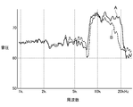
- FIG. 5 shows a comparison between the frequency characteristics of the speaker diaphragm of the present invention and the frequency characteristics of a conventional speaker diaphragm made of a single piece of paper material.
- the solid line A indicates the example of the present invention, and the broken line B indicates the conventional example. .
- the frequency characteristics in FIG. 5 were measured in an anechoic room.
- Inventive Example A and Conventional Example B were prepared using paper materials formed with the same blending ratio of pulp, carbon fiber, and biocellulose, but with different basis weights.
- the center cap portion 1a and the cone portion 1b can be vibrated in the same phase even at 12 kHz, and the split resonance can be reduced. For this reason, as shown in FIG. 5, in the example A of the present invention, a good sound pressure characteristic can be obtained even at a high frequency of 12 kHz after 10 kHz as compared with the conventional example B.
- the cone portion 1b of the body member 1 having a basis weight of 40 g / m 2 also in the specification of the basis weight 40 g / m 2 of the present invention example of the caliber formed by joining the ring member 2 A, suppressing the increase in mass As a result, sound pressure was secured up to about 20 kHz, and good frequency characteristics were obtained.
- the frequency characteristics can be fine-tuned by changing the mixing ratio of carbon fiber and biocellulose to pulp.
- one ring member 2 is bonded to the cone portion 1b, but the rigidity can be adjusted by using a plurality of bonded structures.
- the combination of the body member 1 and the ring member 2 is not limited to the same type of material, but may be a combination of different materials such as resin and metal.
Landscapes
- Engineering & Computer Science (AREA)
- Physics & Mathematics (AREA)
- Acoustics & Sound (AREA)
- Signal Processing (AREA)
- Multimedia (AREA)
- Manufacturing & Machinery (AREA)
- Diaphragms For Electromechanical Transducers (AREA)
Abstract
La présente invention est configurée de telle sorte que, un élément annulaire est lié à une section conique formée sur la circonférence externe d'un corps de plaque vibrante, et la section circonférentielle interne d'un bord est liée à la section de circonférence externe de l'élément annulaire ou de la section de cône. Ainsi, la rigidité est augmentée sans nécessiter un changement de la forme du corps de plaque vibrante, c'est-à-dire, la rigidité est améliorée sans provoquer une augmentation du poids du corps de plaque de vibration, et une dégradation de la pression acoustique à des fréquences élevées est évitée.
Priority Applications (2)
| Application Number | Priority Date | Filing Date | Title |
|---|---|---|---|
| CN201980060655.9A CN112840675B (zh) | 2018-09-18 | 2019-09-12 | 扬声器用振动板 |
| US17/274,971 US11418869B2 (en) | 2018-09-18 | 2019-09-12 | Speaker diaphragm |
Applications Claiming Priority (2)
| Application Number | Priority Date | Filing Date | Title |
|---|---|---|---|
| JP2018173208A JP7255047B2 (ja) | 2018-09-18 | 2018-09-18 | スピーカ用振動板 |
| JP2018-173208 | 2018-09-18 |
Publications (1)
| Publication Number | Publication Date |
|---|---|
| WO2020059638A1 true WO2020059638A1 (fr) | 2020-03-26 |
Family
ID=69888498
Family Applications (1)
| Application Number | Title | Priority Date | Filing Date |
|---|---|---|---|
| PCT/JP2019/035952 Ceased WO2020059638A1 (fr) | 2018-09-18 | 2019-09-12 | Plaque vibrante pour haut-parleurs |
Country Status (5)
| Country | Link |
|---|---|
| US (1) | US11418869B2 (fr) |
| JP (1) | JP7255047B2 (fr) |
| CN (1) | CN112840675B (fr) |
| TW (1) | TW202021381A (fr) |
| WO (1) | WO2020059638A1 (fr) |
Families Citing this family (3)
| Publication number | Priority date | Publication date | Assignee | Title |
|---|---|---|---|---|
| JP1707377S (ja) | 2021-08-31 | 2022-02-14 | ヘッドホン | |
| JP1710048S (ja) * | 2021-08-31 | 2022-03-16 | ヘッドホン | |
| USD1022962S1 (en) * | 2022-06-16 | 2024-04-16 | Hogtunes, Inc. | Speaker base |
Citations (5)
| Publication number | Priority date | Publication date | Assignee | Title |
|---|---|---|---|---|
| JPS5329137Y2 (fr) * | 1973-04-13 | 1978-07-21 | ||
| JPH08102993A (ja) * | 1994-10-03 | 1996-04-16 | Foster Electric Co Ltd | 逆ドーム型スピーカ |
| JP2003348691A (ja) * | 2002-05-28 | 2003-12-05 | Sony Corp | スピーカ装置 |
| JP2006217122A (ja) * | 2005-02-02 | 2006-08-17 | Hosiden Corp | スピーカの振動系及びその振動系の製造方法 |
| JP2009010512A (ja) * | 2007-06-26 | 2009-01-15 | Citizen Electronics Co Ltd | 動電型マイクロスピーカ及びその製造方法 |
Family Cites Families (15)
| Publication number | Priority date | Publication date | Assignee | Title |
|---|---|---|---|---|
| JPS50144426A (fr) | 1974-05-09 | 1975-11-20 | ||
| JPS5329137B2 (fr) | 1974-06-19 | 1978-08-18 | ||
| JPS58233B2 (ja) * | 1978-11-29 | 1983-01-05 | シャープ株式会社 | スピ−カ振動板の製造方法 |
| JPS60260295A (ja) * | 1984-06-07 | 1985-12-23 | Matsushita Electric Ind Co Ltd | スピ−カ |
| JP3930126B2 (ja) | 1997-11-14 | 2007-06-13 | 松下電器産業株式会社 | スピーカ |
| JP4518243B2 (ja) * | 2004-03-12 | 2010-08-04 | パイオニア株式会社 | スピーカ用振動板及びその製造方法 |
| JP4228998B2 (ja) * | 2004-05-27 | 2009-02-25 | パナソニック株式会社 | スピーカ |
| US20080053745A1 (en) * | 2006-08-30 | 2008-03-06 | Takumu Tada | Electroacoustic transducer and diaphragm |
| WO2008099504A1 (fr) | 2007-02-16 | 2008-08-21 | Kyushu Electric Power Co., Inc. | Procédé de prédiction de la situation de traction d'un câble dans un conduit |
| JP5329137B2 (ja) | 2008-07-02 | 2013-10-30 | 京楽産業.株式会社 | パチンコ遊技機 |
| KR101629641B1 (ko) * | 2009-02-20 | 2016-06-13 | 엘지전자 주식회사 | 휴대 단말기 및 그 제어방법 |
| JP4999899B2 (ja) | 2009-09-03 | 2012-08-15 | フォスター電機株式会社 | 電気音響変換器用振動板の製造方法および振動板 |
| US8442259B2 (en) * | 2010-06-04 | 2013-05-14 | Beats Electronics, Llc | System for vibration confinement |
| GB2505953B (en) | 2012-09-18 | 2019-05-08 | B & W Group Ltd | Stepped thickness change in dome-shaped diaphragms for loudspeaker drive units or microphones |
| US9277324B2 (en) | 2013-12-19 | 2016-03-01 | Apple Inc. | Three part membrane speaker |
-
2018
- 2018-09-18 JP JP2018173208A patent/JP7255047B2/ja active Active
-
2019
- 2019-09-12 CN CN201980060655.9A patent/CN112840675B/zh active Active
- 2019-09-12 US US17/274,971 patent/US11418869B2/en active Active
- 2019-09-12 WO PCT/JP2019/035952 patent/WO2020059638A1/fr not_active Ceased
- 2019-09-17 TW TW108133403A patent/TW202021381A/zh unknown
Patent Citations (5)
| Publication number | Priority date | Publication date | Assignee | Title |
|---|---|---|---|---|
| JPS5329137Y2 (fr) * | 1973-04-13 | 1978-07-21 | ||
| JPH08102993A (ja) * | 1994-10-03 | 1996-04-16 | Foster Electric Co Ltd | 逆ドーム型スピーカ |
| JP2003348691A (ja) * | 2002-05-28 | 2003-12-05 | Sony Corp | スピーカ装置 |
| JP2006217122A (ja) * | 2005-02-02 | 2006-08-17 | Hosiden Corp | スピーカの振動系及びその振動系の製造方法 |
| JP2009010512A (ja) * | 2007-06-26 | 2009-01-15 | Citizen Electronics Co Ltd | 動電型マイクロスピーカ及びその製造方法 |
Also Published As
| Publication number | Publication date |
|---|---|
| JP7255047B2 (ja) | 2023-04-11 |
| CN112840675A (zh) | 2021-05-25 |
| CN112840675B (zh) | 2022-08-19 |
| US20220038809A1 (en) | 2022-02-03 |
| TW202021381A (zh) | 2020-06-01 |
| US11418869B2 (en) | 2022-08-16 |
| JP2020048007A (ja) | 2020-03-26 |
Similar Documents
| Publication | Publication Date | Title |
|---|---|---|
| JP4743793B2 (ja) | スピーカー振動板およびこれを用いたスピーカー | |
| US6745867B2 (en) | Loudspeaker drive unit | |
| US10334367B2 (en) | Electroacoustic transducer | |
| KR20170139320A (ko) | 고막 보호 진동판 | |
| US10291978B2 (en) | Frame, speaker unit using the same, and headphone/earphone | |
| JP2020502840A (ja) | ヘッドホン装置 | |
| WO2021218856A1 (fr) | Haut-parleur d'aigus et système audio d'automobile | |
| CN112840675B (zh) | 扬声器用振动板 | |
| US8532327B2 (en) | Diaphragm and speaker device provided with the same | |
| CN1951149B (zh) | 扬声器 | |
| JP3930126B2 (ja) | スピーカ | |
| US10419845B2 (en) | Headphones and speaker unit | |
| JP6699033B2 (ja) | スピーカの振動板及びスピーカ | |
| JP4042732B2 (ja) | リング型スピーカー | |
| US20220312125A1 (en) | Loudspeaker device | |
| JP3605223B2 (ja) | 逆ドーム型スピーカ | |
| JP2012134640A (ja) | スピーカ | |
| JP6989751B2 (ja) | ダストキャップおよびこれを用いる動電型スピーカー | |
| JP2008205880A (ja) | リング型スピーカーおよびこれを用いたスピーカーシステム | |
| JPH0436520B2 (fr) | ||
| JP5266604B2 (ja) | スピーカー振動板およびこれを用いたスピーカー | |
| JPH0129360B2 (fr) | ||
| KR100853898B1 (ko) | 전기 음향 변환기 | |
| WO2023210103A1 (fr) | Haut-parleur | |
| WO2024241651A1 (fr) | Haut-parleur |
Legal Events
| Date | Code | Title | Description |
|---|---|---|---|
| 121 | Ep: the epo has been informed by wipo that ep was designated in this application |
Ref document number: 19861427 Country of ref document: EP Kind code of ref document: A1 |
|
| NENP | Non-entry into the national phase |
Ref country code: DE |
|
| 122 | Ep: pct application non-entry in european phase |
Ref document number: 19861427 Country of ref document: EP Kind code of ref document: A1 |