WO2020065731A1 - Dispositif de climatisation - Google Patents
Dispositif de climatisation Download PDFInfo
- Publication number
- WO2020065731A1 WO2020065731A1 PCT/JP2018/035479 JP2018035479W WO2020065731A1 WO 2020065731 A1 WO2020065731 A1 WO 2020065731A1 JP 2018035479 W JP2018035479 W JP 2018035479W WO 2020065731 A1 WO2020065731 A1 WO 2020065731A1
- Authority
- WO
- WIPO (PCT)
- Prior art keywords
- indoor
- electric expansion
- refrigerant
- expansion valve
- state
- Prior art date
- Legal status (The legal status is an assumption and is not a legal conclusion. Google has not performed a legal analysis and makes no representation as to the accuracy of the status listed.)
- Ceased
Links
Images



Classifications
-
- F—MECHANICAL ENGINEERING; LIGHTING; HEATING; WEAPONS; BLASTING
- F24—HEATING; RANGES; VENTILATING
- F24F—AIR-CONDITIONING; AIR-HUMIDIFICATION; VENTILATION; USE OF AIR CURRENTS FOR SCREENING
- F24F11/00—Control or safety arrangements
- F24F11/70—Control systems characterised by their outputs; Constructional details thereof
- F24F11/80—Control systems characterised by their outputs; Constructional details thereof for controlling the temperature of the supplied air
- F24F11/86—Control systems characterised by their outputs; Constructional details thereof for controlling the temperature of the supplied air by controlling compressors within refrigeration or heat pump circuits
-
- F—MECHANICAL ENGINEERING; LIGHTING; HEATING; WEAPONS; BLASTING
- F25—REFRIGERATION OR COOLING; COMBINED HEATING AND REFRIGERATION SYSTEMS; HEAT PUMP SYSTEMS; MANUFACTURE OR STORAGE OF ICE; LIQUEFACTION SOLIDIFICATION OF GASES
- F25B—REFRIGERATION MACHINES, PLANTS OR SYSTEMS; COMBINED HEATING AND REFRIGERATION SYSTEMS; HEAT PUMP SYSTEMS
- F25B1/00—Compression machines, plants or systems with non-reversible cycle
-
- F—MECHANICAL ENGINEERING; LIGHTING; HEATING; WEAPONS; BLASTING
- F25—REFRIGERATION OR COOLING; COMBINED HEATING AND REFRIGERATION SYSTEMS; HEAT PUMP SYSTEMS; MANUFACTURE OR STORAGE OF ICE; LIQUEFACTION SOLIDIFICATION OF GASES
- F25B—REFRIGERATION MACHINES, PLANTS OR SYSTEMS; COMBINED HEATING AND REFRIGERATION SYSTEMS; HEAT PUMP SYSTEMS
- F25B13/00—Compression machines, plants or systems, with reversible cycle
Definitions
- the embodiment of the present invention relates to a multi-type air conditioner having at least one outdoor unit and a plurality of indoor units.
- a multi-type air conditioner having at least one outdoor unit and a plurality of indoor units is characterized in that a refrigerant discharged from a compressor is passed through a four-way valve, an outdoor heat exchanger, a decompressor, and each indoor heat exchanger. Equipped with a heat pump refrigeration cycle.
- a part of the refrigerant may accumulate in the indoor heat exchanger of the indoor unit, and the refrigerant circulation amount in the refrigeration cycle may be insufficient.
- the refrigerant discharged from the compressor flows into each of the indoor heat exchangers, and the refrigerant flowing out of each of the indoor heat exchangers flows through each of the second electric expansion valve and the first electric expansion valve to the outdoor heat exchanger.
- the controller opens the second electric expansion valve in an indoor unit in an operation-on state according to a heating load among the indoor units, and opens the second electric expansion valve in an indoor unit in an operation-off state in accordance with a heating load. Is fully closed. Further, the controller opens the second electric expansion valve in at least one of the indoor units in the operation-off state to a predetermined opening when the refrigerant circulation amount in the refrigeration cycle is insufficient.
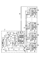
- FIG. 1 is a diagram illustrating an overall configuration of each embodiment. The figure which shows the heat pump refrigeration cycle in each embodiment, the outdoor controller, and each indoor controller. 5 is a flowchart illustrating control according to the first embodiment.
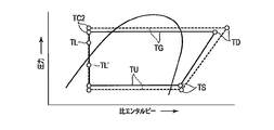
- FIG. 3 is a Mollier chart showing a change in refrigerant temperature TL in each embodiment.
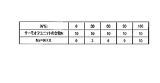
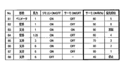
- FIG. 4 is a diagram illustrating control conditions according to the first embodiment.
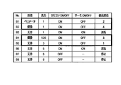
- FIG. 9 is a diagram for explaining control according to the second embodiment.
- FIG. 9 is a diagram for explaining control according to the third embodiment. The figure for explaining the control of a 4th embodiment.
- one outdoor unit A has a rated capacity (also referred to as a rated capacity) of 1 horsepower and is used in a perimeter-type indoor unit B1 (also referred to as a blowing mode), and has a rated capacity of 1 horsepower.
- a rated capacity also referred to as a rated capacity
- the rated capacity is 1 horsepower and the type of use is a ceiling-mounted (4-way blowout) indoor unit B3.
- the rated capacity is 1.25 horsepower and the type of use is a wall-mounted indoor unit B4. Is connected to an indoor unit B5 of 3 horsepower and of a form embedded in the ceiling, and an indoor unit B6 to B8 of a rated capacity of 6 horsepower and used in a form of embedded ceiling.
- a four-way valve 3 is connected to a discharge port of the compressor 1 in the outdoor unit A via a high-pressure pipe 2, and the four-way valve 3 is connected to the outdoor heat exchanger 5 via a gas-side pipe 4.
- One end is connected.
- a decompressor for example, an electric expansion valve (first electric expansion valve) 7 is connected to the other end of the outdoor heat exchanger 5 via a liquid side pipe 6, and the other end of the electric expansion valve 7 is connected to a liquid side pipe 8.
- the packed valve 9 is connected via the.
- the electric expansion valve 7 is a pulse motor valve (PMV) whose opening degree Qo changes according to the number of input drive pulse signals.
- the opening Qo is continuous from the minimum opening Qomin (fully closed) corresponding to “0” drive pulse signals pls to the maximum opening Qmax (full open) corresponding to “3000” drive pulse signals pls. Can be changed to
- a liquid-side transfer pipe 31 is connected to the packed valve 9, and the liquid-side transfer pipe 31 is connected to each indoor heat in each of the indoor units via the electric expansion valves (second electric expansion valves) 41 of the indoor units B1 to B8.
- One end of the exchanger 42 is connected, and the other end of the indoor heat exchanger 42 is connected to the packed valve 10 via the gas side crossing pipe 32.
- Each electric expansion valve 41 is a pulse motor valve (PMV) whose opening degree Qi changes according to the number of input drive pulse signals.
- the opening Qi is continuously from the minimum opening Qimin (fully closed) corresponding to “0” drive pulse signals pls to the maximum opening Qimax (full open) corresponding to “1500” drive pulse signals pls. Can be changed to
- the four-way valve 3 is connected to the packed valve 10 via a gas side pipe 11, and the inflow port of the accumulator 13 is connected to the four-way valve 3 via a low pressure side pipe 12.
- the suction cup 15 of the compressor 1 is connected to the outlet of the accumulator via a low-pressure pipe 14.
- a heat pump refrigeration cycle is configured by these pipe connections.
- the compressor 1 is a hermetic compressor in which a motor 1M operated by the output of the inverter 18 is housed in a hermetically sealed case.
- the compressor 1 sucks the refrigerant flowing out of the accumulator 13 and compresses and discharges the sucked refrigerant.
- the inverter 18 converts the voltage of the AC power supply 19 into a DC voltage, and converts the DC voltage into a frequency F (referred to as an output frequency F) according to a command from the outdoor controller 20 and an AC voltage having a level corresponding to the output frequency F. Convert and output.
- the speed of the motor 1M that is, the capacity of the compressor 1 changes according to the value of the output frequency F.
- the refrigerant discharged from the compressor 1 passes through the four-way valve 3, the outdoor heat exchanger 5, the electric expansion valve 7, and the electric expansion valves 41 to the indoor heat exchangers 42 as indicated by solid arrows. Inflow.
- the refrigerant flowing out of each indoor heat exchanger 42 is sucked into the compressor 1 through the four-way valve 3 and the accumulator 13.
- the outdoor heat exchanger 5 functions as a condenser, and each indoor heat exchanger 42 functions as an evaporator.
- each indoor heat exchanger 42 functions as a condenser
- the outdoor heat exchanger 5 functions as an evaporator.
- An outdoor fan 16 that draws in outside air and supplies the outdoor air to the outdoor heat exchanger 5 is disposed near the outdoor heat exchanger 5.
- An outside air temperature sensor 17 for detecting an outside air temperature To is arranged in a flow path of outside air sucked by the outdoor fan 16.
- a temperature sensor 21 for detecting a refrigerant temperature TD on the high pressure side and a pressure sensor 22 for detecting a refrigerant pressure PD on the high pressure side are attached to the high pressure side pipe 2 between the discharge port of the compressor 1 and the four-way valve 3. .
- a temperature sensor 23 for detecting the refrigerant temperature TL is attached to the liquid side pipe 8 between the electric expansion valve 7 and the packed valve 9.
- a temperature sensor 24 for detecting the low-pressure side refrigerant temperature TS and a pressure sensor 25 for detecting the low-pressure side refrigerant pressure PS are attached to the low-pressure side pipe 12 between the four-way valve 3 and the accumulator 13.
- An indoor fan 43 that sucks indoor air and supplies the indoor air to each indoor heat exchanger 42 is disposed near each of the indoor heat exchangers 42.
- An indoor temperature sensor 44 for detecting the indoor temperature Ta is arranged in a flow path of the indoor air sucked by the indoor fan 43.
- a temperature sensor 47 for detecting the temperature TC2 of the refrigerant flowing out of each indoor heat exchanger 42 during heating is attached to the other end side of each indoor heat exchanger 42.
- a temperature sensor 48 that detects the temperature TC1 of the refrigerant flowing into each indoor heat exchanger 42 during heating is attached.
- the detection signals of these temperature sensors 47 and 48 are sent to each indoor controller 45.
- Each indoor controller 45 has a remote control type operation device (so-called remote control) for allowing a user to specify various operating conditions such as a cooling operation, a dehumidifying operation, a heating operation, a blowing operation, a target indoor temperature Tas, an operation start, and an operation stop. ) 46 are respectively connected.
- the compressor 1, the four-way valve 3, the outdoor heat exchanger 5, the electric expansion valve 7, the packed valves 9, 10, the accumulator 13, the outdoor fan 16, the inverter 18, the outdoor controller 20, each pipe, and each sensor are an outdoor unit.
- the indoor heat exchangers 42, the outdoor fans 43, the indoor controllers 45, the operating devices 46, the pipes, and the sensors are housed in N indoor units B1, B2,..., Bn.
- the outdoor unit A and the indoor units B1, B2,... Bn constitute a multi-type air conditioner.
- the outdoor controller 20 and each indoor controller 45 are connected to each other by a signal line 50 for data transmission.
- the indoor controller 45 of the indoor unit B1 closes the electric expansion valve 41 and shuts off the flow of the refrigerant to the indoor heat exchanger 42 when the operation stop is designated by the operation unit 46. Is put into operation stop state. Further, when the heating operation and the operation ON are designated by the operation device 46, the indoor controller 45 of the indoor unit B1 turns on the indoor fan 43 in the slight wind mode for the detection of the indoor temperature Ta by the indoor temperature sensor 44. Then, the difference between the detected room temperature Ta and the target room temperature Tas specified by the operation device 46 is detected as the heating load.
- the indoor controller 45 of the indoor unit B1 opens the electric expansion valve 41 and circulates the refrigerant to the indoor heat exchanger 42, whereby the indoor unit B1 Is in a driving-on state (referred to as a thermo-on state). If the detected heating load is larger than zero, the electric expansion valve 41 is fully closed to shut off the flow of the refrigerant to the indoor heat exchanger 42, thereby turning off the indoor unit B1 (referred to as a thermo-off state).
- the indoor controllers 45 of the other indoor units B2 to Bn also execute the same control as the indoor controller 45 of the indoor unit B1.
- the outdoor controller 20 controls the operation of the outdoor unit A and the indoor units B1 to Bn in cooperation with each of the indoor controllers 45, and has a first control section 20a, a second control section 20b, a detection section 20c as main functions.
- a third control section 20d is included.
- the first control section 20a controls the opening degree Qo of the electric expansion valve 7 so that the superheat degree (superheat) SH of the refrigerant in the outdoor heat exchanger (evaporator) 5 becomes the target value SHs during the heating operation. Execute superheat control.
- the superheat degree SH of the refrigerant corresponds to the difference between the detected temperature TL of the temperature sensor 23 and the detected temperature TS of the temperature sensor 24.
- the second control section 20b controls the electric expansion of the indoor unit in the thermo-on state so that the subcooling degree SC of the refrigerant in the indoor heat exchanger (condenser) 42 of the indoor unit in the thermo-on state becomes the target value SCs.
- the supercooling degree control for operating the opening degree Qi of the valve 41 is executed, and the electric expansion valve 41 of the indoor unit in the thermo-off state is fully closed.
- the difference between the condensation temperature TG of the refrigerant in each indoor heat exchanger 42 and the detection temperature TC2 of each temperature sensor 47 can be obtained as the degree of supercooling SC.
- the condensation temperature TG can be obtained by conversion from the high pressure side refrigerant pressure PD detected by the pressure sensor 22 of the high pressure side pipe 2.
- the second control section 20b reduces the target value SCs for the supercooling degree SC when the heating load of the indoor unit in the thermo-on state increases with the execution of the supercooling degree control, and thereby the electric expansion valve 7 Is changed in the increasing direction, thereby increasing the flow rate of the refrigerant to the indoor heat exchanger 42 and increasing the heating capacity.
- the opening value Qo of the electric expansion valve 7 is changed in a decreasing direction by increasing the target value SCs with respect to the supercooling degree SC, thereby changing the indoor heat exchanger 42. To decrease the heating capacity by reducing the flow rate of the refrigerant.
- the detection section 20c detects the refrigerant circulation amount in the heat pump refrigeration cycle during the heating operation, and specifically detects the shortage rate X (%) of the refrigerant circulation amount.
- the third control section 20d specifically sets the shortage rate X detected by the detection section 20c to a threshold Xs (for example, 30%) or more and cannot be ignored.
- the electric expansion valve 41 in at least one of the indoor units in the thermo-off state is opened to a predetermined opening.
- the third control section 20d determines the number of indoor units corresponding to the detected shortage rate among the indoor units in the thermo-off state.
- the electric expansion valve 41 is opened to a predetermined opening Qis (for example, about 3 to 5% of the maximum opening Qimax).
- the shortage rate X of the refrigerant circulation amount is the condensation temperature TG of the refrigerant in the condenser, the evaporation temperature TU of the refrigerant in the evaporator (the indoor heat exchanger 42), and the temperature of the refrigerant flowing out of the evaporator (the temperature detected by the temperature sensor 47). It can be detected using any one or more of TC2 and the temperature TL of the refrigerant flowing into the condenser (the temperature detected by the temperature sensor 23).
- the evaporation temperature TU can be obtained by conversion from the detection pressure PS of the pressure sensor 25 in the low-pressure side pipe 12.
- the liquid-side crossing pipe 31 and the liquid-side pipes 8 and 7 become liquid.
- the liquid refrigerant flows into the outdoor heat exchanger (evaporator) 5.
- the refrigerant accumulates in one of the indoor units B1 to Bn and the circulation amount of the refrigerant in the heat pump refrigeration cycle becomes insufficient, the liquid refrigerant and the gaseous The refrigerant coexists and flows, so-called gas-liquid two-phase refrigerant flows into the outdoor heat exchanger 5.
- the superheat degree SH of the refrigerant in the outdoor heat exchanger 5 increases, and the superheat degree control works to suppress the increase in the superheat degree SH. 7, the opening Qo changes in the increasing direction. However, if the opening Qo of the electric expansion valve 7 continues to increase and reaches the maximum opening Qmax of the electric expansion valve 7, the increase in the superheat SH cannot be suppressed, and the suction into the compressor 1 is stopped. The temperature TS of the supplied refrigerant rises.
- the output frequency F of the inverter 18 decreases due to the high-pressure protection control of the indoor controller 20 against the increase in the refrigerant temperature TD. I do.
- the output frequency F decreases, the capacity of the compressor 1 decreases, and accordingly, the heating capacity of the indoor unit in the operating state decreases.
- the state of the heat pump refrigeration cycle in the case where the liquid refrigerant flows into the outdoor heat exchanger 5 is shown by a solid line in the Mollier diagram in FIG. 3, and the state in which the refrigerant in the gas-liquid two-phase state flows into the outdoor heat exchanger 5
- the state of the heat pump refrigeration cycle is shown by a broken line in the Mollier diagram.
- the refrigerant temperature TL is closer to the condensation temperature TG when a liquid refrigerant flows in, but is a value TL deviating from the condensation temperature TG and closer to the evaporation temperature TU when a gas-liquid two-phase refrigerant flows in. '.
- the detection section 20c determines which position between the refrigerant temperature TL and the refrigerant temperature TL ′ in the Mollier diagram is present by the refrigerant circulation TL detected by the temperature sensor 23. It is detected as a quantity shortage rate X (%). That is, if the actual refrigerant temperature TL is at the same position as the refrigerant temperature TL on the Mollier diagram, the shortage ratio X is 0%, and the actual refrigerant temperature TL is the difference between the refrigerant temperature TL and the refrigerant temperature TL ′ on the Mollier diagram.
- the shortage ratio X is 50% when the refrigerant temperature is at an intermediate position between them, and 100% when the actual refrigerant temperature TL is at the same position as the refrigerant temperature TL 'on the Mollier diagram.
- the outdoor controller 20 controls the opening of the electric expansion valve 7 so that the superheat degree SH of the refrigerant in the outdoor heat exchanger (evaporator) 5 becomes the target value SHs (S1).
- the outdoor controller 20 operates the electric expansion valves of the indoor units B1 and B2 so that the supercooling degree SC of the refrigerant in the indoor heat exchangers 42 of the indoor units B1 and B2 in the thermo-on state becomes the target value SCs, respectively.
- the opening degree Qi of 41 is controlled, and the electric expansion valves 41 of, for example, the indoor units B4 to B6 in the thermo-off state are fully closed (S2). Further, the outdoor controller 20 fully closes, for example, the electric expansion valves 41 of the indoor units B7 and B8 in the operation stopped state.
- the outdoor controller 20 detects the shortage rate X of the refrigerant circulation amount in the heat pump refrigeration cycle (S3), and determines whether the detected shortage rate X is equal to or larger than the threshold Xs (S4). If the detected shortage rate X is not equal to or larger than the threshold value Xs (NO in S4), the outdoor controller 20 repeats the processing from S1.
- the outdoor controller 20 electrically drives the Nx indoor units corresponding to the detected insufficiency rate X out of the N indoor units in the thermo-off state, for example.
- the valve 41 is opened to a predetermined opening Qis (S5).
- the outdoor controller 20 starts a time count t (S6), and determines whether or not the time count t has reached a certain time ts (for example, 300 seconds). Is determined (S7). If the time count t is less than the fixed time ts (NO in S7), the outdoor controller 20 holds the open state of each electric expansion valve 41 (S8) and continues the time count t (S6). Then, when the time count t has reached the predetermined time ts (YES in S7), the outdoor controller 20 returns to S3 and detects the shortage rate X of the refrigerant circulation amount again (S3).
- a time count t for example, 300 seconds.
- the outdoor controller 20 sets the N indoor units in the thermo-off state. Among them, the electric expansion valves 41 in the Nx indoor units corresponding to the shortage rate X detected this time are opened to the predetermined opening Qis (S5).
- the same electric expansion valve 41 as the previous time is kept open.
- the electric expansion valves 41 of some indoor units are newly opened to a predetermined opening degree in addition to keeping the same electric expansion valves 41 as in the previous time. Open to Qis.
- the electric expansion valve 41 of at least one indoor unit in the thermo-off state is opened, so that the stagnant refrigerant accumulated in the indoor unit is transferred to the liquid side crossing pipe 31 and the liquid side. It flows out to the pipe 8. Thereby, the gas-liquid two-phase state of the refrigerant in the liquid-side transition pipe 31 and the liquid-side pipes 8 and 7 can be eliminated.
- the superheat degree SH of the refrigerant in the outdoor heat exchanger 5 can be prevented from being unnecessarily increased, so that the electric expansion valve 7 can be controlled by the superheat degree control. Unnecessary increase in the opening Qo can be prevented. With this, it is possible to avoid an unnecessary increase in the temperature TS of the refrigerant sucked into the compressor 1, and to thereby avoid an unnecessary increase in the temperature TD (and the pressure PD) of the refrigerant discharged from the compressor 1. Accordingly, it is possible to avoid an unnecessary decrease in the output frequency F of the inverter 18 due to the high-voltage protection control. As a result, it is possible to prevent unnecessary decrease in the heating capacity of the indoor unit in the operating state.
- the gaseous refrigerant discharged from the compressor 1 flows into the indoor heat exchanger 42, so that an unnecessary indoor temperature rise occurs in the indoor unit in the thermo-off state.
- the electric expansion valve 41 opens only at the predetermined opening Qis, an unnecessary increase in the room temperature can be avoided as much as possible.
- the third control section 20d of the outdoor controller 20 in the second embodiment is configured such that when the refrigerant circulation amount detected by the detection section 20c is insufficient, the shortage rate X detected by the detection section 20c is equal to or greater than the threshold Xs.
- the electric expansion valves 41 of the indoor units in the thermo-off state are opened to the predetermined opening Qis in order according to the priority order according to the rated capacity (horsepower) of the indoor unit in the thermo-off state.
- the indoor units B1, B2, B4, B5, and B6 perform the heating operation, the operation of the indoor units B3, B7, and B8 are stopped, and the heating operation is being performed.
- the outdoor controller 20 outputs the thermo-off indoor units B1, B4, and B5.
- the indoor unit B5 having a rated capacity of 3 hp is set to the first place
- the indoor unit B4 having the rated capacity of 1.25 hp is set to the second place
- the indoor unit B1 having the rated capacity of 1 hp is set to the third place.
- the outdoor controller 20 opens the electric expansion valve 41 of the indoor unit B5 having the highest priority to the predetermined opening Qis, and after a predetermined time ts, the priority is second.
- the electric expansion valve 41 of the indoor unit B4 is opened to the predetermined opening Qis, and after a predetermined time ts, the electric expansion valve 41 of the indoor unit B1 having the third priority is opened to the predetermined opening Qis.
- the rated capacity of the indoor unit is related to the size of the air-conditioned space in which the indoor unit is installed. That is, an indoor unit B5 with a large rated capacity is installed in a large room, and an indoor unit B1 with a small rated capacity is installed in a small room.
- the increase in the room temperature that occurs when the electric expansion valve 41 of the indoor unit B5 installed in the large room is opened is the amount of room temperature that occurs when the electric expansion valve 41 of the indoor unit B1 that is installed in the small room is open. Less than the rise.
- the third control section 20d of the outdoor controller 20 is configured such that when the refrigerant circulation amount detected by the detection section 20c is insufficient, the shortage rate X detected by the detection section 20c is equal to or greater than the threshold Xs.
- the electric expansion valves 41 in the indoor units in the thermo-off state are opened to the predetermined opening degrees Qis in order according to the priority order according to the usage mode (including the air blowing mode) of the indoor units in the thermo-off state. .
- the indoor units B1 to B6 perform the heating operation and the operation of the indoor units B7 and B8 are stopped by the designation of each operation device 46, and the indoor units B1 to B6 in the heating operation are among
- the outdoor controller 20 determines that the indoor units B1, B2, B4, B5 in the thermo-off state have a priority order of ceiling.
- the embedded indoor unit B5 is ranked first, the perimeter-type indoor unit B1 is ranked second, and the wall-mounted indoor units B4 and B2 are ranked third and fourth.
- the outdoor controller 20 sets the indoor unit B4 having the larger rated capacity of 3 hp to the third place and the indoor unit B2 having the smaller rated capacity of 1 hp to the fourth place. Set to.
- the outdoor controller 20 opens the electric expansion valve 41 of the indoor unit B5 having the highest priority to the predetermined opening Qis, and after a predetermined time ts, the priority is second.
- the electric expansion valve 41 of the indoor unit B1 is opened to the predetermined opening Qis, and after a certain time ts, the electric expansion valve 41 of the indoor unit B4 having the third priority is opened to the predetermined opening Qis, and after a predetermined time ts Then, the electric expansion valve 41 of the indoor unit B2 having the fourth priority is opened to the predetermined opening Qis.
- the indoor unit B5 embedded in the ceiling is installed in a relatively large room, and the indoor units B4 and B2 mounted on the wall are installed in a relatively small room.
- Wall-mounted indoor units B4 and B2 may be installed near the user so that the heated air directly hits the user's body. For this reason, the increasing range of the indoor temperature generated when the electric expansion valve 41 of the indoor unit B5 embedded in the ceiling is opened is the indoor temperature generated when the electric expansion valve 41 of the indoor units B4 and B2 mounted on the wall is opened. Is smaller than the rise of
- the third control section 20d of the outdoor controller 20 is configured such that when the refrigerant circulation amount detected by the detection section 20c is insufficient, the shortage rate X detected by the detection section 20c is equal to or larger than the threshold Xs.
- the electric expansion valves 41 in the indoor units in the thermo-off state are set to predetermined values in order according to the priorities corresponding to the past thermo-on rates (operation on-rates) D (%) of the indoor units in the thermo-off state. Open to opening Qis.
- the outdoor controller 20 monitors the integrated operation times tm of the indoor units B1 to Bn, and monitors the integrated thermo-on times ton of the indoor units B1 to Bn, respectively, and calculates the ratio of the integrated thermo-on time ton to the integrated operation time tm. It is sequentially calculated as the thermo-on rate D (%) of the indoor units B1 to Bn.
- the operation integrated time tm is an integrated value of the time from when the indoor unit starts operating until it stops.
- the thermo-on integrated time ton is an integrated value of the time when the indoor unit is in the thermo-on state.
- the indoor units B1 to B7 perform the heating operation to stop the operation of the indoor unit B8, and the indoor unit B3 of the indoor units B1 to B7 during the heating operation is designated by the respective operation devices 46. Is turned on and the indoor units B1, B2, B4 to B7 are turned off, the outdoor controller 20 sets the thermo-on rate D to 90 (%) as the priority of the indoor units B1, B2, B4 to B7 in the thermo-off state.
- Units B4 and B1 are set to fourth and fifth places, and indoor unit B2 with a thermo-on rate D of 50 (%) is set to sixth. Since the indoor units B4 and B1 have the same thermo-on rate D, the outdoor controller 20 sets the indoor unit B4 having the larger rated capacity of 1.25 hp to the fourth place and the smaller indoor unit B1 having the rated capacity of 1 hp. Set to 5th place.
- the outdoor controller 20 sequentially opens the electric expansion valves 41 of the indoor units in the thermo-off state to the predetermined opening Qis at predetermined time intervals ts in accordance with the set priority order.
- thermo-on rate D The heating load of the indoor unit having a high thermo-on rate D is large, and the heating load of the indoor unit having a low thermo-on rate D is small.
- the increase in the room temperature that occurs when the electric expansion valve 41 of the indoor unit B7 with a large heating load is opened is larger than the increase in the indoor temperature that occurs when the electric expansion valve 41 of the indoor unit B2 with a small heating load is opened. ,small.
- the position of the actual refrigerant temperature TL detected by the temperature sensor 23 between the refrigerant temperature TL and the refrigerant temperature TL ′ on the Mollier diagram is determined by the shortage of the refrigerant circulation amount.
- the detection is performed as the rate X (%), but the invention is not limited to this, and the point is that the detection is performed using any one or more of the condensation temperature TG, the evaporation temperature TU, the refrigerant temperature TC2, and the refrigerant temperature TL. do it.
- the filling rate Y (%) becomes a value approaching 0% as the shortage of the refrigerant circulation amount increases, and approaches 100% as the shortage of the refrigerant circulation amount decreases.
Landscapes
- Engineering & Computer Science (AREA)
- Physics & Mathematics (AREA)
- Mechanical Engineering (AREA)
- Thermal Sciences (AREA)
- General Engineering & Computer Science (AREA)
- Chemical & Material Sciences (AREA)
- Combustion & Propulsion (AREA)
- Air Conditioning Control Device (AREA)
- Compression-Type Refrigeration Machines With Reversible Cycles (AREA)
Abstract
Parmi des unités intérieures, par rapport à des unités intérieures dans un état de fonctionnement ON correspondant à une charge de chauffage, des seconds détendeurs électriques de celles-ci sont ouverts, et par rapport à l'autre unité intérieure dans un état de fonctionnement OFF correspondant à une charge de chauffage, les seconds détendeurs électriques de celle-ci sont complètement fermés. Lorsque la quantité de fluide frigorigène circulant dans un cycle de réfrigération est insuffisante, le second détendeur électrique dans au moins l'une des unités intérieures à l'état de fonctionnement OFF est ouvert à un degré d'ouverture prédéfini.
Priority Applications (3)
| Application Number | Priority Date | Filing Date | Title |
|---|---|---|---|
| CN201880098077.3A CN112771321A (zh) | 2018-09-25 | 2018-09-25 | 空调装置 |
| PCT/JP2018/035479 WO2020065731A1 (fr) | 2018-09-25 | 2018-09-25 | Dispositif de climatisation |
| JP2020547641A JPWO2020065731A1 (ja) | 2018-09-25 | 2018-09-25 | 空気調和装置 |
Applications Claiming Priority (1)
| Application Number | Priority Date | Filing Date | Title |
|---|---|---|---|
| PCT/JP2018/035479 WO2020065731A1 (fr) | 2018-09-25 | 2018-09-25 | Dispositif de climatisation |
Publications (1)
| Publication Number | Publication Date |
|---|---|
| WO2020065731A1 true WO2020065731A1 (fr) | 2020-04-02 |
Family
ID=69952975
Family Applications (1)
| Application Number | Title | Priority Date | Filing Date |
|---|---|---|---|
| PCT/JP2018/035479 Ceased WO2020065731A1 (fr) | 2018-09-25 | 2018-09-25 | Dispositif de climatisation |
Country Status (3)
| Country | Link |
|---|---|
| JP (1) | JPWO2020065731A1 (fr) |
| CN (1) | CN112771321A (fr) |
| WO (1) | WO2020065731A1 (fr) |
Cited By (1)
| Publication number | Priority date | Publication date | Assignee | Title |
|---|---|---|---|---|
| WO2022059154A1 (fr) * | 2020-09-17 | 2022-03-24 | 東芝キヤリア株式会社 | Climatiseur |
Citations (5)
| Publication number | Priority date | Publication date | Assignee | Title |
|---|---|---|---|---|
| JPH05312428A (ja) * | 1992-05-11 | 1993-11-22 | Daikin Ind Ltd | 空気調和装置の運転制御装置 |
| JPH0835710A (ja) * | 1994-07-22 | 1996-02-06 | Mitsubishi Heavy Ind Ltd | マルチタイプ空気調和機の制御装置 |
| JPH10339479A (ja) * | 1997-06-10 | 1998-12-22 | Mitsubishi Electric Corp | 空気調和装置 |
| JP2005114184A (ja) * | 2003-10-03 | 2005-04-28 | Hitachi Ltd | 冷媒充填装置及び冷媒充填方法 |
| JP2015183859A (ja) * | 2014-03-20 | 2015-10-22 | 株式会社富士通ゼネラル | マルチタイプ空気調和機 |
Family Cites Families (5)
| Publication number | Priority date | Publication date | Assignee | Title |
|---|---|---|---|---|
| CN100580347C (zh) * | 2005-04-07 | 2010-01-13 | 大金工业株式会社 | 空调装置的制冷剂量判定系统 |
| JP4383472B2 (ja) * | 2007-08-27 | 2009-12-16 | 三洋電機株式会社 | 空気調和装置 |
| CN101749825B (zh) * | 2008-12-04 | 2012-10-03 | 珠海格力电器股份有限公司 | 用于复合型空调器的冷媒追加控制方法 |
| CN105276749B (zh) * | 2014-06-24 | 2018-01-30 | 青岛海信日立空调系统有限公司 | 一种多联机空调系统的控制方法及装置 |
| WO2017026025A1 (fr) * | 2015-08-10 | 2017-02-16 | 三菱電機株式会社 | Climatiseur de type multiple |
-
2018
- 2018-09-25 WO PCT/JP2018/035479 patent/WO2020065731A1/fr not_active Ceased
- 2018-09-25 JP JP2020547641A patent/JPWO2020065731A1/ja active Pending
- 2018-09-25 CN CN201880098077.3A patent/CN112771321A/zh not_active Withdrawn
Patent Citations (5)
| Publication number | Priority date | Publication date | Assignee | Title |
|---|---|---|---|---|
| JPH05312428A (ja) * | 1992-05-11 | 1993-11-22 | Daikin Ind Ltd | 空気調和装置の運転制御装置 |
| JPH0835710A (ja) * | 1994-07-22 | 1996-02-06 | Mitsubishi Heavy Ind Ltd | マルチタイプ空気調和機の制御装置 |
| JPH10339479A (ja) * | 1997-06-10 | 1998-12-22 | Mitsubishi Electric Corp | 空気調和装置 |
| JP2005114184A (ja) * | 2003-10-03 | 2005-04-28 | Hitachi Ltd | 冷媒充填装置及び冷媒充填方法 |
| JP2015183859A (ja) * | 2014-03-20 | 2015-10-22 | 株式会社富士通ゼネラル | マルチタイプ空気調和機 |
Cited By (2)
| Publication number | Priority date | Publication date | Assignee | Title |
|---|---|---|---|---|
| WO2022059154A1 (fr) * | 2020-09-17 | 2022-03-24 | 東芝キヤリア株式会社 | Climatiseur |
| US12366374B2 (en) | 2020-09-17 | 2025-07-22 | Carrier Japan Corporation | Air conditioner |
Also Published As
| Publication number | Publication date |
|---|---|
| CN112771321A (zh) | 2021-05-07 |
| JPWO2020065731A1 (ja) | 2021-08-30 |
Similar Documents
| Publication | Publication Date | Title |
|---|---|---|
| JP4497234B2 (ja) | 空気調和装置 | |
| JP6642379B2 (ja) | 空調機 | |
| EP2339256B1 (fr) | Climatiseur et procédé de commande correspondant | |
| JP5831661B1 (ja) | 空調機 | |
| JP5979112B2 (ja) | 冷凍装置 | |
| JP2019020112A (ja) | 空調システム | |
| CN101082441A (zh) | 空调机 | |
| CN114364933A (zh) | 空调机 | |
| US10480837B2 (en) | Refrigeration apparatus | |
| JP5506433B2 (ja) | マルチ型空気調和機 | |
| JPH06201176A (ja) | 空気調和機 | |
| JP2007218532A (ja) | 空気調和装置 | |
| JP4302874B2 (ja) | 空気調和機 | |
| CN116576513A (zh) | 一种空调系统及其控制方法 | |
| US11835273B2 (en) | Refrigerant cycle apparatus | |
| JP6918221B2 (ja) | 空気調和機 | |
| JP6747226B2 (ja) | 冷凍装置 | |
| WO2020065731A1 (fr) | Dispositif de climatisation | |
| JP5884381B2 (ja) | 冷凍装置の室外ユニット | |
| CN116642247A (zh) | 一种空调系统及其控制方法 | |
| JP6245207B2 (ja) | 空気調和装置 | |
| JP7047120B2 (ja) | 空気調和装置 | |
| WO2022059075A1 (fr) | Climatiseur | |
| JP6115594B2 (ja) | 空調室内機 | |
| JP6507598B2 (ja) | 空調システム |
Legal Events
| Date | Code | Title | Description |
|---|---|---|---|
| 121 | Ep: the epo has been informed by wipo that ep was designated in this application |
Ref document number: 18934987 Country of ref document: EP Kind code of ref document: A1 |
|
| ENP | Entry into the national phase |
Ref document number: 2020547641 Country of ref document: JP Kind code of ref document: A |
|
| NENP | Non-entry into the national phase |
Ref country code: DE |
|
| 122 | Ep: pct application non-entry in european phase |
Ref document number: 18934987 Country of ref document: EP Kind code of ref document: A1 |