WO2020067478A1 - テーププリプレグ、テーププリプレグの配置方法、繊維強化複合材料及び繊維強化複合材料の製造方法 - Google Patents
テーププリプレグ、テーププリプレグの配置方法、繊維強化複合材料及び繊維強化複合材料の製造方法 Download PDFInfo
- Publication number
- WO2020067478A1 WO2020067478A1 PCT/JP2019/038269 JP2019038269W WO2020067478A1 WO 2020067478 A1 WO2020067478 A1 WO 2020067478A1 JP 2019038269 W JP2019038269 W JP 2019038269W WO 2020067478 A1 WO2020067478 A1 WO 2020067478A1
- Authority
- WO
- WIPO (PCT)
- Prior art keywords
- tape
- prepreg
- tape prepreg
- width direction
- composite material
- Prior art date
- Legal status (The legal status is an assumption and is not a legal conclusion. Google has not performed a legal analysis and makes no representation as to the accuracy of the status listed.)
- Ceased
Links
Images





Classifications
-
- B—PERFORMING OPERATIONS; TRANSPORTING
- B29—WORKING OF PLASTICS; WORKING OF SUBSTANCES IN A PLASTIC STATE IN GENERAL
- B29C—SHAPING OR JOINING OF PLASTICS; SHAPING OF MATERIAL IN A PLASTIC STATE, NOT OTHERWISE PROVIDED FOR; AFTER-TREATMENT OF THE SHAPED PRODUCTS, e.g. REPAIRING
- B29C70/00—Shaping composites, i.e. plastics material comprising reinforcements, fillers or preformed parts, e.g. inserts
- B29C70/04—Shaping composites, i.e. plastics material comprising reinforcements, fillers or preformed parts, e.g. inserts comprising reinforcements only, e.g. self-reinforcing plastics
- B29C70/06—Fibrous reinforcements only
- B29C70/10—Fibrous reinforcements only characterised by the structure of fibrous reinforcements, e.g. hollow fibres
- B29C70/16—Fibrous reinforcements only characterised by the structure of fibrous reinforcements, e.g. hollow fibres using fibres of substantial or continuous length
- B29C70/20—Fibrous reinforcements only characterised by the structure of fibrous reinforcements, e.g. hollow fibres using fibres of substantial or continuous length oriented in a single direction, e.g. roofing or other parallel fibres
-
- B—PERFORMING OPERATIONS; TRANSPORTING
- B29—WORKING OF PLASTICS; WORKING OF SUBSTANCES IN A PLASTIC STATE IN GENERAL
- B29C—SHAPING OR JOINING OF PLASTICS; SHAPING OF MATERIAL IN A PLASTIC STATE, NOT OTHERWISE PROVIDED FOR; AFTER-TREATMENT OF THE SHAPED PRODUCTS, e.g. REPAIRING
- B29C70/00—Shaping composites, i.e. plastics material comprising reinforcements, fillers or preformed parts, e.g. inserts
- B29C70/04—Shaping composites, i.e. plastics material comprising reinforcements, fillers or preformed parts, e.g. inserts comprising reinforcements only, e.g. self-reinforcing plastics
- B29C70/28—Shaping operations therefor
- B29C70/30—Shaping by lay-up, i.e. applying fibres, tape or broadsheet on a mould, former or core; Shaping by spray-up, i.e. spraying of fibres on a mould, former or core
-
- B—PERFORMING OPERATIONS; TRANSPORTING
- B29—WORKING OF PLASTICS; WORKING OF SUBSTANCES IN A PLASTIC STATE IN GENERAL
- B29C—SHAPING OR JOINING OF PLASTICS; SHAPING OF MATERIAL IN A PLASTIC STATE, NOT OTHERWISE PROVIDED FOR; AFTER-TREATMENT OF THE SHAPED PRODUCTS, e.g. REPAIRING
- B29C70/00—Shaping composites, i.e. plastics material comprising reinforcements, fillers or preformed parts, e.g. inserts
- B29C70/04—Shaping composites, i.e. plastics material comprising reinforcements, fillers or preformed parts, e.g. inserts comprising reinforcements only, e.g. self-reinforcing plastics
- B29C70/28—Shaping operations therefor
- B29C70/30—Shaping by lay-up, i.e. applying fibres, tape or broadsheet on a mould, former or core; Shaping by spray-up, i.e. spraying of fibres on a mould, former or core
- B29C70/302—Details of the edges of fibre composites, e.g. edge finishing or means to avoid delamination
-
- B—PERFORMING OPERATIONS; TRANSPORTING
- B29—WORKING OF PLASTICS; WORKING OF SUBSTANCES IN A PLASTIC STATE IN GENERAL
- B29C—SHAPING OR JOINING OF PLASTICS; SHAPING OF MATERIAL IN A PLASTIC STATE, NOT OTHERWISE PROVIDED FOR; AFTER-TREATMENT OF THE SHAPED PRODUCTS, e.g. REPAIRING
- B29C70/00—Shaping composites, i.e. plastics material comprising reinforcements, fillers or preformed parts, e.g. inserts
- B29C70/04—Shaping composites, i.e. plastics material comprising reinforcements, fillers or preformed parts, e.g. inserts comprising reinforcements only, e.g. self-reinforcing plastics
- B29C70/28—Shaping operations therefor
- B29C70/40—Shaping or impregnating by compression not applied
- B29C70/50—Shaping or impregnating by compression not applied for producing articles of indefinite length, e.g. prepregs, sheet moulding compounds [SMC] or cross moulding compounds [XMC]
-
- C—CHEMISTRY; METALLURGY
- C08—ORGANIC MACROMOLECULAR COMPOUNDS; THEIR PREPARATION OR CHEMICAL WORKING-UP; COMPOSITIONS BASED THEREON
- C08J—WORKING-UP; GENERAL PROCESSES OF COMPOUNDING; AFTER-TREATMENT NOT COVERED BY SUBCLASSES C08B, C08C, C08F, C08G or C08H
- C08J5/00—Manufacture of articles or shaped materials containing macromolecular substances
- C08J5/04—Reinforcing macromolecular compounds with loose or coherent fibrous material
- C08J5/0405—Reinforcing macromolecular compounds with loose or coherent fibrous material with inorganic fibres
- C08J5/042—Reinforcing macromolecular compounds with loose or coherent fibrous material with inorganic fibres with carbon fibres
-
- C—CHEMISTRY; METALLURGY
- C08—ORGANIC MACROMOLECULAR COMPOUNDS; THEIR PREPARATION OR CHEMICAL WORKING-UP; COMPOSITIONS BASED THEREON
- C08J—WORKING-UP; GENERAL PROCESSES OF COMPOUNDING; AFTER-TREATMENT NOT COVERED BY SUBCLASSES C08B, C08C, C08F, C08G or C08H
- C08J5/00—Manufacture of articles or shaped materials containing macromolecular substances
- C08J5/24—Impregnating materials with prepolymers which can be polymerised in situ, e.g. manufacture of prepregs
- C08J5/241—Impregnating materials with prepolymers which can be polymerised in situ, e.g. manufacture of prepregs using inorganic fibres
- C08J5/243—Impregnating materials with prepolymers which can be polymerised in situ, e.g. manufacture of prepregs using inorganic fibres using carbon fibres
-
- C—CHEMISTRY; METALLURGY
- C08—ORGANIC MACROMOLECULAR COMPOUNDS; THEIR PREPARATION OR CHEMICAL WORKING-UP; COMPOSITIONS BASED THEREON
- C08J—WORKING-UP; GENERAL PROCESSES OF COMPOUNDING; AFTER-TREATMENT NOT COVERED BY SUBCLASSES C08B, C08C, C08F, C08G or C08H
- C08J5/00—Manufacture of articles or shaped materials containing macromolecular substances
- C08J5/24—Impregnating materials with prepolymers which can be polymerised in situ, e.g. manufacture of prepregs
- C08J5/248—Impregnating materials with prepolymers which can be polymerised in situ, e.g. manufacture of prepregs using pre-treated fibres
-
- B—PERFORMING OPERATIONS; TRANSPORTING
- B29—WORKING OF PLASTICS; WORKING OF SUBSTANCES IN A PLASTIC STATE IN GENERAL
- B29C—SHAPING OR JOINING OF PLASTICS; SHAPING OF MATERIAL IN A PLASTIC STATE, NOT OTHERWISE PROVIDED FOR; AFTER-TREATMENT OF THE SHAPED PRODUCTS, e.g. REPAIRING
- B29C2793/00—Shaping techniques involving a cutting or machining operation
- B29C2793/0063—Cutting longitudinally
-
- B—PERFORMING OPERATIONS; TRANSPORTING
- B29—WORKING OF PLASTICS; WORKING OF SUBSTANCES IN A PLASTIC STATE IN GENERAL
- B29C—SHAPING OR JOINING OF PLASTICS; SHAPING OF MATERIAL IN A PLASTIC STATE, NOT OTHERWISE PROVIDED FOR; AFTER-TREATMENT OF THE SHAPED PRODUCTS, e.g. REPAIRING
- B29C70/00—Shaping composites, i.e. plastics material comprising reinforcements, fillers or preformed parts, e.g. inserts
- B29C70/04—Shaping composites, i.e. plastics material comprising reinforcements, fillers or preformed parts, e.g. inserts comprising reinforcements only, e.g. self-reinforcing plastics
- B29C70/28—Shaping operations therefor
- B29C70/30—Shaping by lay-up, i.e. applying fibres, tape or broadsheet on a mould, former or core; Shaping by spray-up, i.e. spraying of fibres on a mould, former or core
- B29C70/38—Automated lay-up, e.g. using robots, laying filaments according to predetermined patterns
- B29C70/386—Automated tape laying [ATL]
- B29C70/388—Tape placement heads, e.g. component parts, details or accessories
-
- B—PERFORMING OPERATIONS; TRANSPORTING
- B29—WORKING OF PLASTICS; WORKING OF SUBSTANCES IN A PLASTIC STATE IN GENERAL
- B29K—INDEXING SCHEME ASSOCIATED WITH SUBCLASSES B29B, B29C OR B29D, RELATING TO MOULDING MATERIALS OR TO MATERIALS FOR MOULDS, REINFORCEMENTS, FILLERS OR PREFORMED PARTS, e.g. INSERTS
- B29K2063/00—Use of EP, i.e. epoxy resins or derivatives thereof, as moulding material
-
- B—PERFORMING OPERATIONS; TRANSPORTING
- B29—WORKING OF PLASTICS; WORKING OF SUBSTANCES IN A PLASTIC STATE IN GENERAL
- B29K—INDEXING SCHEME ASSOCIATED WITH SUBCLASSES B29B, B29C OR B29D, RELATING TO MOULDING MATERIALS OR TO MATERIALS FOR MOULDS, REINFORCEMENTS, FILLERS OR PREFORMED PARTS, e.g. INSERTS
- B29K2307/00—Use of elements other than metals as reinforcement
- B29K2307/04—Carbon
-
- C—CHEMISTRY; METALLURGY
- C08—ORGANIC MACROMOLECULAR COMPOUNDS; THEIR PREPARATION OR CHEMICAL WORKING-UP; COMPOSITIONS BASED THEREON
- C08J—WORKING-UP; GENERAL PROCESSES OF COMPOUNDING; AFTER-TREATMENT NOT COVERED BY SUBCLASSES C08B, C08C, C08F, C08G or C08H
- C08J2363/00—Characterised by the use of epoxy resins; Derivatives of epoxy resins
-
- C—CHEMISTRY; METALLURGY
- C08—ORGANIC MACROMOLECULAR COMPOUNDS; THEIR PREPARATION OR CHEMICAL WORKING-UP; COMPOSITIONS BASED THEREON
- C08J—WORKING-UP; GENERAL PROCESSES OF COMPOUNDING; AFTER-TREATMENT NOT COVERED BY SUBCLASSES C08B, C08C, C08F, C08G or C08H
- C08J2363/00—Characterised by the use of epoxy resins; Derivatives of epoxy resins
- C08J2363/02—Polyglycidyl ethers of bis-phenols
-
- C—CHEMISTRY; METALLURGY
- C08—ORGANIC MACROMOLECULAR COMPOUNDS; THEIR PREPARATION OR CHEMICAL WORKING-UP; COMPOSITIONS BASED THEREON
- C08J—WORKING-UP; GENERAL PROCESSES OF COMPOUNDING; AFTER-TREATMENT NOT COVERED BY SUBCLASSES C08B, C08C, C08F, C08G or C08H
- C08J2481/00—Characterised by the use of macromolecular compounds obtained by reactions forming in the main chain of the macromolecule a linkage containing sulfur with or without nitrogen, oxygen, or carbon only; Polysulfones; Derivatives of such polymers
- C08J2481/06—Polysulfones; Polyethersulfones
Definitions
- the present invention relates to a tape prepreg, a method for disposing a tape prepreg, a fiber-reinforced composite material, and a method for producing a fiber-reinforced composite material.
- fiber-reinforced composite materials comprising a reinforcing fiber and a matrix resin have light weight and excellent mechanical properties, they are widely used in aerospace applications, automotive applications, sports applications, and various other industrial applications.
- the fiber reinforced composite material is obtained mainly by heating and molding a prepreg for a fiber reinforced composite material, which is an intermediate material.
- Prepreg is obtained by impregnating a reinforcing fiber with a thermosetting resin or a thermoplastic resin.
- thermosetting resins are mainly used in view of the heat resistance and strength of the fiber-reinforced composite material. Among them, fiber reinforced with excellent heat resistance, elastic modulus, low curing shrinkage, chemical resistance, etc. Epoxy resin is most often used because a composite material can be obtained.
- a prepreg called a tape prepreg disclosed in Patent Document 1 is often used in order to efficiently form a large-sized, three-dimensionally shaped strength member.
- This is a prepreg in which a roll of prepreg is cut in the longitudinal direction to increase the aspect ratio.
- the tape prepreg is usually cut into a width of 1/4 inch (6.4 mm) to 6 inches (152 mm) and set in a laminating device called an auto lay-up device.
- a laminating apparatus a plurality of tape prepregs are spread on the surface of a mold having a desired shape so as to be adjacent to each other in the width direction, and are laminated and crimped to have a desired thickness in a desired fiber direction.
- the laminate is heated and cured using an autoclave, an oven, or the like, to obtain a target fiber-reinforced composite material.
- Patent Literature 2 proposes a tape prepreg having a substantially rectangular cross section and little variation in width. However, even if the cross section is rectangular, it is practically difficult to completely eliminate the variation in width, and it is actually difficult to completely cover the width without any gap. For this reason, there is a problem that it is difficult to develop a good appearance in which the reinforcing fibers and the resin are not missing and a strength in calculation. In addition, there is a problem in that the fibers are likely to be missing.
- the present invention relates to a tape prepreg capable of providing a fiber reinforced composite material having reduced fiber loss, excellent mechanical properties, and excellent thickness dimensional accuracy, a fiber reinforced composite material using the tape prepreg, and a method for producing the same. I will provide a.
- the inventors of the present invention have conducted intensive studies to solve the above-described problems, and as a result, have made the end portion of the cross section in the width direction of the tape prepreg thinner than the center portion, and placed the thin end portions so as to overlap each other. Then, they found that a fiber-reinforced composite material having sufficient appearance and strength could be obtained by molding, and completed the present invention. That is, the gist of the present invention is as follows.
- a vertical cross section in the orientation direction of the reinforcing fiber bundle has a portion where the thickness continuously increases from one end and the other end in the width direction toward the center in the width direction, and the thickness of the vertical cross section is
- the tape according to [1] wherein at least a part of an upper side and a lower side, which are boundaries in the thickness direction of the vertical cross section, has straight portions parallel to each other, and the acute angle is 40 ° to 85 °.
- the method further comprises: arranging a plurality of the tape prepregs according to any one of [1] to [4] so as to align the orientation directions of the reinforcing fiber bundles so as to be adjacent to each other, and applying heat and pressure.
- a method for producing a fiber-reinforced composite material At the time of the disposition, the end in the width direction of the first tape prepreg and the end in the width direction of the second tape prepreg are arranged so as to overlap with each other when viewed in the thickness direction, producing a fiber-reinforced composite material.
- a tape prepreg obtained by impregnating a resin into a reinforcing fiber bundle in which reinforcing fibers are aligned in one direction, wherein a vertical cross section in the orientation direction of the reinforcing fiber bundle has one end and the other end in the width direction.
- a tape prepreg having a portion whose thickness continuously increases from the center to the center in the width direction, wherein the tape prepreg includes a release sheet.
- the tape prepreg according to [9] wherein upper and lower sides of the vertical cross section have different lengths, and the release sheet is disposed on a surface of the tape prepreg on a shorter side.
- a vertical cross section in the orientation direction of the reinforcing fiber bundle of the tape prepreg has a portion where the thickness continuously increases from one end and the other end in the width direction toward the center in the width direction, and the tape
- a plurality of the tape prepregs are arranged so that the orientation directions of the reinforcing fiber bundles are aligned and adjacent to each other, and at the time of the arrangement, at least a part of the first tape prepreg and the second tape prepreg
- At least a part of the continuously increasing thickness portion of the first tape prepreg and at least a part of the continuously increasing thickness portion of the second tape prepreg overlap with each other.
- a vertical cross section in the orientation direction of the reinforcing fiber bundle of the tape prepreg has a portion where the thickness continuously increases from one end and the other end in the width direction toward the center in the width direction, and the tape
- a tape prepreg which can provide a fiber reinforced composite material in which the loss of fibers and resins is reduced, is excellent in mechanical properties, and is excellent in thickness dimensional accuracy, and a fiber reinforced composite material using the tape prepreg And a method of manufacturing the same.
- FIG. 1 is a perspective view in which a plurality of tape prepregs 1 are arranged on the upper surface Wa of a plate-shaped mold W so that the plurality of tape prepregs 1 are arranged adjacent to each other in the longitudinal direction.
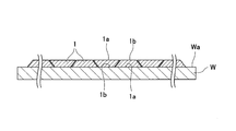
- FIG. 2 is a cross-sectional view of the tape prepreg 1 taken along the line II-II of FIG. 1 in the thickness direction.
- FIG. 3 is a top view of the plurality of tape prepregs 1 arranged on the top surface Wa of the mold W in FIG.
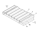
- FIG. 4 is a perspective view in which a plurality of tape prepregs 2 are arranged on the upper surface Wa of a flat mold W so that the plurality of tape prepregs 2 are arranged adjacent to each other in the longitudinal direction.
- FIG. 1 is a perspective view in which a plurality of tape prepregs 1 are arranged on the upper surface Wa of a plate-shaped mold W so that the plurality of tape prepregs 1 are arranged adjacent to each other in the
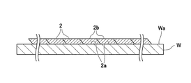
- FIG. 5 is a cross-sectional view taken along the line VV of FIG. 4 in the thickness direction of the tape prepreg 2.
- FIG. 6 is a top view of the plurality of tape prepregs 2 arranged on the top surface Wa of the mold W in FIG.
- FIG. 7 is a cross-sectional view of the groove roll 5 including the groove 4 having a trapezoidal cross section.
- FIG. 8 is a vertical sectional view of a modified example of the tape prepreg 1 of the first embodiment.
- FIG. 9 is a vertical sectional view of another modified example of the tape prepreg 1 of the first embodiment.
- FIG. 10 is a vertical sectional view of a modified example of the tape prepreg 2 of the second embodiment.
- FIG. 11 is a vertical sectional view of another modified example of the tape prepreg 2 of the second embodiment.
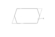
- FIG. 12 is a schematic diagram illustrating a method for measuring the size of the angle formed by the upper or lower side of the tape prepreg and the oblique side according to the present invention.
- the following term definitions apply throughout the present description and claims.
- “Rectangle” refers to a quadrilateral in which all four interior angles are equal and right.
- matrix resin refers to a resin component that exists around the reinforcing fibers and maintains the shape in the fiber-reinforced composite material. There are thermosetting, thermoplastic, or mixtures thereof.
- the “prepreg for fiber-reinforced composite material” refers to a material in which a plurality of reinforcing fibers are aligned, impregnated with a matrix resin, and formed into a sheet.
- “Tape prepreg” refers to a prepreg for a fiber-reinforced composite material in the form of a tape.
- slit tape prepreg refers to a material obtained by cutting a prepreg for a fiber-reinforced composite material along the longitudinal direction of the fiber so as to have a width smaller than that of the original prepreg for the fiber-reinforced composite material.
- fiber-reinforced composite material refers to a material obtained by heating and curing a sheet in which a plurality of tape prepregs are arranged adjacent to each other in the width direction, or a laminated sheet in which a plurality of the sheets are laminated.
- the tape prepreg of the present invention is a tape in which a reinforcing fiber bundle in which reinforcing fibers are aligned in one direction is impregnated with a resin.
- the vertical cross section in the orientation direction of the reinforcing fiber bundle has a portion where the thickness continuously increases from one end and the other end in the width direction toward the center in the width direction, and the thickness of the vertical cross section is Preferably, the angle between any one of the boundary lines in the direction and the boundary line in the width direction is an acute angle.
- the upper side (one side of the tape prepreg) which is a boundary line in the thickness direction of the vertical cross section is obtained. It is preferable that at least a part of the lower side (a side forming the other surface of the tape prepreg) and a lower side (a side forming the other surface of the tape prepreg) have linear portions parallel to each other. Preferably, the straight portion includes the center.
- the bulge of the overlapped portion is reduced, so that the angle formed by any one of the upper side and the lower side and the oblique side which is the boundary line in the width direction.
- the acute angle is preferably from 40 to 85 °, and more preferably from 45 to 80 °.
- the angle formed by any one of the upper side and the lower side and the oblique side that is the boundary line is formed by unwinding the prepared tape prepreg, cutting it to a length of 2 cm, freezing it, and slicing the sliced surface on the upper surface. In this state, the lower surface is embedded in clay, and the end is observed at a magnification of 100 times.
- the outermost end and the thickness direction existing within a range of 1500 ⁇ m from the outermost end.
- An angle formed by a straight line connecting the prepreg center and the apex of the protrusion projecting in the opposite direction to the center of the prepreg is measured. That is, a straight line T2 connecting the extreme end and the apex of the convex portion protruding in the opposite direction to the center of the prepreg among the unevenness of the boundary line in the prepreg thickness direction, and the unevenness of the boundary line in the prepreg width direction in the prepreg width direction.
- the magnitude of the angle ⁇ formed by the straight line T1 connecting the center of the prepreg and the apex of the protrusion projecting in the opposite direction is measured.
- the tape prepreg may include a release sheet.
- a release sheet When the lengths of the upper side and the lower side of the vertical cross section in the orientation direction of the reinforcing fiber bundle are different, when the release sheet is disposed on the tape prepreg surface on the shorter side, a surface having a large bonding area is bonded to the mold. Since it is possible, it is difficult to form a void in the molded body.
- the release sheet when the release sheet is disposed on the surface of the tape prepreg on the longer side, the side surfaces of the tape prepreg can be exposed, so that the prepregs can be arranged without gaps when they are laminated and bonded.
- the tape prepreg is preferably a slit tape prepreg because its shape can be easily adjusted.
- FIG. 1 is a perspective view in which a plurality of tape prepregs 1 are arranged on the upper surface Wa of a plate-shaped mold W so that the plurality of tape prepregs 1 are arranged adjacent to each other in the longitudinal direction.
- FIG. 2 is a cross-sectional view of the tape prepreg 1 taken along the line II-II of FIG. 1 in the thickness direction.
- FIG. 3 is a top view of the plurality of tape prepregs 1 arranged on the top surface Wa of the mold W in FIG.
- the orientation directions of the reinforcing fibers constituting the reinforcing fiber bundle of the tape prepreg 1 are aligned in one direction along the longitudinal direction of the tape prepreg 1.
- the shape of the vertical cross section of the tape prepreg 1 orthogonal to the orientation direction is a trapezoid.
- the boundary in the thickness direction of the vertical cross section is the base of the trapezoid
- the longest base of the trapezoid is called the lower side 1a (lower base)
- the bottom side is referred to as an upper side 1b (upper bottom).
- the lower side 1a and the upper side 1b have straight portions parallel to each other.
- Two oblique sides (trapezoidal legs) which are boundary lines in the width direction connecting the lower side 1a and the upper side 1b are inclined with respect to the upper surface Wa of the mold W.
- the middle point from one end to the other end of the lower side 1a is the center in the width direction.
- the upper side 1b and the lower side 1a have straight portions parallel to each other, and among these straight portions, the straight portion of the lower side 1a has the center, and the straight portion of the upper side 1b intersects a perpendicular line lowered from the center.
- the lower side 1a of the trapezoid represented by the vertical cross section of the first tape prepreg 1 is located on the opposite side of the upper surface Wa of the mold W and is exposed upward.
- the lower side 1a of the trapezoid represented by the vertical section of the second tape prepreg 1 adjacent thereto is in contact with the upper surface Wa of the mold W.
- the front side (the surface on the lower side 1a side) and the back side (the surface on the upper side 1b side) of each tape prepreg 1 are alternately adjacent to each other, so that the end of the lower side 1a of the first tape prepreg 1 becomes the second side.
- the lower side 1a of the tape prepreg 1 in the thickness direction.
- each tape prepreg 1 when viewed from above, the end of the lower side 1a of the trapezoid represented by the vertical section of each tape prepreg 1 is the end of the lower side 1a of the trapezoid represented by the vertical section of the adjacent tape prepreg 1.
- the overlap width S1 of the adjacent tape prepregs 1 is preferably 0.01 to 2 mm, more preferably 0.05 to 1.5 mm, and further preferably 0.1 to 1 mm. preferable.
- the width S1 is within this range, the end portions of the adjacent tape prepregs 1 are combined and appropriately overlap with each other, and it is easy to arrange the tape prepregs 1 adjacent to each other without any gap.
- the length ratio R represented by (length of the lower side 1a of the trapezoid / length of the upper side 1b of the trapezoid) is preferably 1.003 to 2.67, 1.02 to 1.88 is more preferable, and 1.03 to 1.45 is still more preferable.
- the length ratio R is within this range, the end portions of the adjacent tape prepregs 1 are combined and appropriately overlap with each other, and it is easy to arrange the tape prepregs 1 adjacent to each other without any gap.
- the length of the lower side 1a of the trapezoid is preferably 1 to 26 mm, more preferably 3 to 20 mm, and still more preferably 6 to 13 mm.
- the length of the upper side 1b of the trapezoid is preferably 2 to 12.98 mm, more preferably 3 to 12.9 mm, and further preferably 4 to 12.8 mm.
- the thickness of the trapezoid is preferably from 10 to 1,000 ⁇ m, more preferably from 100 to 750 ⁇ m, even more preferably from 200 to 500 ⁇ m.
- the ends of the adjacent tape prepregs 1 are combined and overlap appropriately, and each tape prepreg is overlapped. It is easy to arrange them so that they are adjacent to each other without any gap.
- the shape of the vertical cross section of the tape prepreg 1 is a trapezoid
- the midpoint of the lower side 1a and the midpoint of the upper side 1b overlap in the thickness direction.
- the trapezoid has a line-symmetrical cross-sectional shape such that the left and right sides of the trapezoid overlap when folded back at a line connecting the midpoint of the lower side 1a and the midpoint of the upper side 1b.
- the vertical cross-sectional shapes of the tape prepregs 1 arranged on the upper surface Wa of the mold W are substantially the same.
- the shape of the vertical cross section of the tape prepreg 1 of the first embodiment described above is an isosceles trapezoid, but it may be modified based on this trapezoid.
- the vertical section of the tape prepreg 1 is a dome shape in which the obtuse angle formed by the upper side (upper bottom) of the trapezoid and the leg is rounded as shown in FIG. 8 or the lower side of the trapezoid as shown in FIG. It may be a hexagonal shape in which an acute-angled apex formed by the (lower bottom) and the leg is cut off.
- the vertical section of the tape prepreg 1 has a portion whose thickness continuously increases from one end and the other end in the width direction toward the center in the width direction, At least a part of the upper side and the lower side of the vertical cross section have straight portions parallel to each other.
- FIG. 4 is a perspective view in which a plurality of tape prepregs 2 are arranged on the upper surface Wa of a flat mold W so that the plurality of tape prepregs 2 are arranged adjacent to each other in the longitudinal direction.
- FIG. 5 is a cross-sectional view taken along the line VV of FIG. 4 in the thickness direction of the tape prepreg 2.
- FIG. 6 is a top view of the plurality of tape prepregs 2 arranged on the top surface Wa of the mold W in FIG.
- the orientation direction of the reinforcing fibers constituting the reinforcing fiber bundle of the tape prepreg 2 is aligned in one direction along the longitudinal direction of the tape prepreg 2.
- the shape of the vertical cross section of the tape prepreg 2 orthogonal to the orientation direction is a parallelogram.
- the parallelogram has the same length on the opposite sides, the same diagonal size, and the diagonal passes through the midpoint of another diagonal.
- rectangles and squares having a diagonal of 90 degrees are not included in the parallelogram.
- the longest bottom side of the parallelogram is referred to as a lower side 2a, and the side opposite to the lower side 2a is referred to as an upper side 2b.
- the lower side 2a and the upper side 2b have straight portions parallel to each other. Two oblique sides connecting the lower side 2a and the upper side 2b are inclined with respect to the upper surface Wa of the mold W.
- the middle point from one end to the other end of the lower side 2a is the center in the width direction.
- the lower side 2a of the first tape prepreg 2 is in contact with the upper surface Wa of the mold W, and the upper side 2b is located on the opposite side of the upper surface Wa of the mold W and is exposed upward. ing.
- the lower side 2a and the upper side 2b of the second tape prepreg 2 adjacent thereto are the same as those of the first tape prepreg 1.
- the end of the lower side 2a of the first tape prepreg 2 overlaps the end of the upper side 2b of the second tape prepreg 2 as viewed in the thickness direction.
- each tape prepreg 2 when seen through from above, overlaps the end of the upper side 2b of the adjacent tape prepreg 2.
- the tape prepreg 2 may be viewed from above. A portion where the prepreg 2 does not exist (a gap between adjacent tape prepregs 2) hardly occurs.
- the overlap width S2 of the adjacent tape prepregs 2 is preferably 0.01 to 2 mm, more preferably 0.05 to 1.5 mm, and further preferably 0.1 to 1 mm. preferable.
- the width S2 is within this range, the ends of the adjacent tape prepregs 2 are combined and overlap appropriately, and it is easy to arrange the tape prepregs 2 adjacent to each other without any gap.
- the acute angle of the inner angles is preferably 40 to 85 °, more preferably 50 to 80 °, and further preferably 60 to 75 °. If the magnitude of the acute angle is within this range, the ends of the adjacent tape prepregs 2 are combined and overlap appropriately, and it is easy to arrange the tape prepregs 2 adjacent to each other without any gap.
- the length of the lower side 2a and the upper side 2b of the parallelogram is preferably 1 to 26 mm, more preferably 3 to 20 mm, and still more preferably 6 to 13 mm.
- the thickness (distance between the lower side 1a and the upper side 1b) of the parallelogram is preferably from 10 to 1,000 ⁇ m, more preferably from 100 to 750 ⁇ m, and further preferably from 200 to 500 ⁇ m.
- the shapes of the vertical cross sections of the tape prepregs 2 arranged on the upper surface Wa of the mold W are substantially the same.
- the shape of the vertical cross section of the tape prepreg 2 of the second embodiment described above is a parallelogram, but it may be modified based on this parallelogram.
- the vertical cross section of the tape prepreg 2 has a dome shape with rounded corners at both ends of the upper side of the parallelogram as shown in FIG. 10, or an acute vertex portion of the parallelogram as shown in FIG. 11. It may be a hexagon that is cut off.
- the vertical cross section has a portion where the thickness continuously increases from one end and the other end in the width direction toward the center in the width direction, and the upper side of the vertical cross section And at least a part of the lower side has straight portions parallel to each other.
- the tape prepreg described above is obtained by impregnating a reinforcing fiber bundle in which reinforcing fibers are arranged in one direction with a resin (matrix resin). Next, examples of the material of the tape prepreg of the present invention will be described.
- the reinforcing fibers include carbon fibers, aramid fibers, nylon fibers, high-strength polyester fibers, glass fibers, boron fibers, alumina fibers, and silicon nitride fibers.
- carbon fibers, aramid fibers, glass fibers, boron fibers, alumina fibers, and silicon nitride fibers are preferable in terms of excellent flame retardancy, and carbon fibers are particularly preferable in terms of excellent specific strength and specific elasticity.
- the diameter and length of the fiber may be the same as in the conventional case.
- thermosetting resin As the matrix resin, a thermoplastic resin or a thermosetting resin is preferable.
- the thermosetting resin include an epoxy resin, a vinyl ester resin, an unsaturated polyester resin, and a polyimide.
- An epoxy resin excellent in the price of the material, the ease of adjusting the viscosity, the balance of the mechanical properties of the cured product, and the like is preferable.
- the type of the resin contained in the matrix resin may be one type alone, or may be two or more types.
- the viscosity of the resin is preferably 20,000 Pa ⁇ s or more, more preferably 30,000 Pa ⁇ s or more, from the viewpoint of maintaining a shape having a portion where the thickness continuously increases toward the center in the width direction of the tape. From the viewpoint of handleability, 100000 Pa ⁇ s or less is preferable, and 50,000 Pa ⁇ s or less is more preferable.
- epoxy resin an epoxy resin using an amine, a phenol, or a compound having a carbon-carbon double bond as a precursor is particularly preferable.
- epoxy resins having amines as precursors include various isomers of tetraglycidyldiaminodiphenylmethane, triglycidyl-p-aminophenol, triglycidyl-m-aminophenol, and triglycidylaminocresol.
- Can be Tetraglycidyl diaminodiphenylmethane is preferable because it has excellent heat resistance as a resin for a fiber-reinforced composite material for aircraft structural materials.
- Examples of the epoxy resin having a phenol as a precursor include bisphenol A epoxy resin, bisphenol F epoxy resin, bisphenol S epoxy resin, phenol novolak epoxy resin, cresol novolak epoxy resin, and resorcinol epoxy resin. Since liquid bisphenol A-type epoxy resins and bisphenol F-type epoxy resins have low viscosities, their viscosities are generally adjusted in combination with high viscosities and solid epoxy resins and additives. If the viscosity is too low, the tackiness of the prepreg becomes excessive, the bobbin unwinding property of the slit prepreg becomes poor, and the tapes tend to stick together during lamination.
- the tack of the prepreg can be reduced, so there is an effect of preventing the adhesion between the prepregs, but if the viscosity is too high, the tack and drape properties are impaired, adhesion to the backing film, Tends to worsen.
- the epoxy resin using a compound having a carbon-carbon double bond as a precursor include an alicyclic epoxy resin. These epoxy resins may be used alone or in a combination of two or more. A combination of a glycidylamine type epoxy resin and a glycidyl ether type epoxy resin is particularly preferable because it has both heat resistance and toughness.
- epoxy resins include jER (registered trademark) 828, 827, 807, 604, 630, 1001, 1002, 1004, 4004, 4007, 1032H60 manufactured by Mitsubishi Chemical Corporation, and EPICLON (registered trademark) 830, 850 manufactured by DIC. , N673, N675, N770, N775, HP4032, HP4700, HP4770, EXA-1514, TACTIX (registered trademark) 742, 556 manufactured by HUNTSMAN ADVANCED MATERIALS, but are not limited thereto.
- thermoplastic resin A thermoplastic resin may be added to the matrix resin as needed. When an epoxy resin is used as the main component of the matrix resin, mixing a thermoplastic resin gives the cured product of the epoxy resin composition a high toughness, suppresses the stickiness of the epoxy resin composition, and adjusts the prepreg tack to an appropriate level. It has the effect of adjusting and controlling the resin flow immediately before curing at high temperatures.
- the thermoplastic resin include polyether sulfone, polyvinyl formal, phenoxy resin, polyamide, and acrylic block copolymer. One of these thermoplastic resins may be used alone, or two or more thereof may be used in combination.
- thermoplastic resin particle layer on the surface of the tape prepreg.
- thermoplastic resin particle layer on the surface of the prepreg having no release sheet from the viewpoint of adhesiveness between the release sheet and the prepreg.
- the slit may be formed after the thermoplastic resin particle layer is provided, or the thermoplastic resin particle layer may be laminated after the slit.
- thermoplastic resin particles By laminating the thermoplastic resin particle layer after slitting, slitting so that the thermoplastic resin particle layer is exposed, etc., the adhesiveness between tapes can be improved by the presence of thermoplastic resin particles also on the slit cross section (side surface). Can be improved.
- thermoplastic resin particles those which are soluble or insoluble in the matrix resin of the prepreg can be used.
- a resin layer for suppressing wrinkles may be provided between the thermoplastic resin particle layer and the fiber layer.
- the resin of the resin layer is preferably a resin having high compatibility with the matrix resin of the prepreg, and both the resin of the resin layer and the matrix resin are preferably epoxy resins.
- the thermoplastic resin particles are preferably polyamide particles.
- additives solid rubber, filler, diluent, solvent, pigment, plasticizer, antioxidant, stabilizer, etc.
- Known additives can be added to the matrix resin as needed.
- carbon black, graphene, or the like is used as a pigment.
- Carbon black and graphene have the effect of coloring the epoxy resin black, hiding the color of the resin when molding the fiber-reinforced composite material described later, and giving a high-quality appearance especially when applied to sports products. Also, it has ultraviolet absorbing ability and heat dissipation function.
- the content of the matrix resin with respect to the total mass of the tape prepreg of the present invention is preferably 15 to 50% by mass, and more preferably 20 to 45% by mass.
- the ratio is equal to or more than the lower limit of the above range, the reinforcing fibers can be sufficiently bonded to each other, and the lack of the reinforcing fibers can be sufficiently suppressed.
- the mechanical properties of the reinforcing fiber can be sufficiently exhibited.
- a backing film (cover film) is preferably attached to the tape prepreg.
- the backing film may be attached before slitting, or may be attached after slitting.
- Examples of the material of the backing film include polyethylene, polypropylene, and polyester.
- the thickness of the backing film is preferably from 10 to 80 ⁇ m.
- the tape prepreg of the present invention can partially apply a known production method. That is, as described in, for example, Patent Documents 1 and 2, a prepreg containing a reinforcing fiber bundle in which reinforcing fibers are aligned in one direction by a known method is prepared, and then the prepreg is passed through a slitter for cutting. To obtain a tape prepreg of width When cutting the prepreg, by applying a blade obliquely to the surface of the prepreg in the slitter so as to have the shape of the above-described vertical cross section, the vertical cross section as in the second embodiment is a parallelogram or trapezoid. Is obtained. Also, as shown in FIG.
- the vertical cross section as in the first embodiment is trapezoidal. You get something.
- the tape prepreg obtained by slitting using a slitter may be further passed through a die having a desired shape to remove unnecessary portions, thereby obtaining a tape prepreg having a desired vertical cross section.
- a vertical cross section in the orientation direction of the reinforcing fiber bundle of the tape prepreg has one end in the width direction and the other end. There is a portion where the thickness continuously increases from the end toward the center in the width direction.
- the tape prepreg of the present invention it is preferable that the tape prepreg of the present invention be heated and disposed on a mold.
- the method for arranging the tape prepreg of the present invention includes arranging a plurality of tape prepregs of the present invention so that the orientation directions of the reinforcing fiber bundles are aligned and adjacent to each other. More preferably, at least a part and at least a part of the second tape prepreg are arranged so as to overlap. In this case, at least a part of the continuously increasing thickness portion of the first tape prepreg and at least a part of the continuously increasing thickness portion of the second tape prepreg overlap each other. Is more preferable.
- a known device can be used as an automatic laminating device (automatic tape placement device).
- an automatic laminating device for example, as shown in JP-A-4-62142 and JP-A-5-200898, a tape prepreg drawn from a supply device is wound around a laminating roll, and pressed into a mold to form a mold. By laminating the laminating rolls along, lamination can be performed.
- the tape prepreg is provided with a heating portion capable of heating the laminated portion, the tape prepreg can be heated to have an adhesive property and be laminated.
- the roll When using a release sheet, the roll provided on the unwinding section that produces the tape prepreg on which the release sheet is placed, the winding section that separates the release sheet from the prepreg tape and winds it up,
- a laminating apparatus having a laminating head that presses while relatively moving, it can be applied to an aspect having a release sheet.
- the fiber reinforced composite material of the present invention is obtained by heating and curing the tape prepreg of the present invention.
- a plurality of tape prepregs may be combined and cured, or a single tape prepreg may be cured.
- the plurality of tape prepregs constituting the fiber-reinforced composite material are arranged so as to be adjacent to each other in the width direction.
- the number of tape prepregs arranged in the width direction is appropriately determined depending on the shape of the fiber-reinforced composite material, and includes, for example, about 10 to 100.
- the plurality of tape prepregs constituting the fiber reinforced composite material may be arranged not only so as to be adjacent to each other in the width direction but also to be stacked in the thickness direction.
- the number of layers is, for example, about 2 to 20 layers.
- the method for producing a fiber-reinforced composite material of the present invention includes disposing a plurality of tape prepregs of the present invention so that the orientation directions of the reinforcing fiber bundles are aligned and adjacent to each other, and applying heat and pressure. It is a method of manufacturing a material. In the above arrangement, the widthwise end of the first tape prepreg and the widthwise end of the second tape prepreg are arranged so as to overlap each other when viewed in the thickness direction.
- the overlap width (S1 in FIG. 3) of the ends of the adjacent tape prepregs 1 in the width direction is preferably 0.01 to 2 mm, more preferably 0.05 to 1.5 mm, and further preferably 0.1 to 1 mm. preferable.
- the width is 0.01 mm or more, even if the dimensional accuracy in the width direction of the tape prepreg 1 is slightly lower, it is easier to keep the tape prepreg within the range of the overlapping width.
- the width is 2 mm or less, it becomes easier to arrange the first tape prepreg 1 and the second tape prepreg 1 such that the ends in the width direction overlap with each other.
- the overlap width (S2 in FIG. 6) between the ends of the adjacent tape prepregs 2 in the width direction is preferably 0.01 to 2 mm, more preferably 0.05 to 1.5 mm, and further preferably 0.1 to 1 mm. preferable.
- the width is 0.01 mm or more, even if the dimensional accuracy in the width direction of the tape prepreg 2 is slightly low, it is easier to keep the tape prepreg within the range of the overlapping width.
- the width is 2 mm or less, it becomes easier to arrange the first tape prepreg 2 and the second tape prepreg 2 such that the ends in the width direction overlap each other.
- the widthwise ends of the first tape prepreg and the second tape prepreg are arranged so as to overlap with each other, and the lower surface of each tape prepreg does not run on the slope of the end of the adjacent tape prepreg.
- the thickness of the fiber-reinforced composite material to be formed can be made uniform.
- the number of tape prepregs arranged in the width direction of the tape prepreg to form the fiber reinforced composite material is appropriately determined depending on the shape of the fiber reinforced composite material, and for example, about 10 to 100.
- the tape prepreg may be laminated not only in the width direction of the tape prepreg but also in the thickness direction of the tape prepreg.
- the number of layers is, for example, about 2 to 20 layers.
- the method for producing the fiber-reinforced composite material of the present invention can be produced by a known method, except that the tape prepreg of the present invention is used and arranged in a predetermined manner.
- a tape prepreg is spread over a molding die having a desired surface shape such as a flat surface or a curved surface using an automatic laminating device (auto lay-up device), vacuum-packed, and then heated to be cured in a desired shape.
- auto lay-up device automatic laminating device
- the temperature and time for heating the tape prepreg are not particularly limited as long as the curing reaction of the impregnated matrix resin is performed. For example, heating conditions of 100 to 200 ° C. for about 1 to 3 hours can be mentioned.
- the pressure to be applied may be a pressure at which the tape prepregs sufficiently adhere to each other in a desired form, and it is preferable to perform heating while keeping the pressure at 100 kPa or less.
- a method of applying pressure for example, there is a method in which a plurality of tape prepregs are spread and sealed in a resin sheet or a resin bag to evacuate the internal space.
- the tape prepreg of the present invention has a section in which the vertical section in the orientation direction of the reinforcing fiber bundle continuously increases in thickness from the end in the width direction toward the center in the width direction, and the upper side of the vertical section. Since the lower side has a straight portion parallel to each other, when the ends are overlapped and stacked by using an automatic laminating apparatus, the overlapping portion does not become thick and can be finished to a uniform thickness. Further, the fiber-reinforced composite material obtained from the tape prepreg of the present invention has excellent mechanical properties and excellent dimensional accuracy because there is no loss of fibers.
- Example 1> (Preparation of matrix resin) 15 parts of tetraglycidyl diaminodiphenylmethane (jER604 manufactured by Mitsubishi Chemical Corporation), 50 parts of liquid bisphenol A type epoxy resin (jER828 manufactured by Mitsubishi Chemical Corporation), 35 parts of oxazolidone ring-modified epoxy resin (TSR-400 manufactured by DIC Corporation), poly 2 parts of ether sulfone (Sumika Excel 5003MP, manufactured by Sumitomo Chemical Co., Ltd.) was mixed in a resin preparation kettle, stirred at 150 ° C. for 2 hours, and dissolved and mixed.
- prepreg for fiber reinforced composite material A prepared 72 g / m 2 resin film was stuck on high strength carbon fibers (TR50S-15K manufactured by Mitsubishi Chemical Corporation) aligned in one direction from above and below, and the fibers were impregnated with the resin by heat and pressure.
- a prepreg for fiber-reinforced composite material having a fiber weight of 268 g / m 2 , a resin content of 35 wt%, and a width of 1000 mm was obtained.
- the obtained prepreg for a fiber-reinforced composite material was set in a dedicated slit machine, inserted into a score cutter having a width of 6.4 mm while being unwound with a constant tension, and slit in the longitudinal direction of the carbon fiber. Thereafter, the release paper was peeled off, and the tape prepreg was continuously pressed against a groove roll (see FIG. 7) having a trapezoidal cross-section sculpted in a post-installed process to form a trapezoidal cross-section. .
- the prepared tape prepreg was unwound, and the thickness at the center in the width direction was measured at 10 places using calipers, and the average was taken as the thickness at the center. Further, the thickness of the tape prepreg at a position of 0.1 mm from the end was measured at 10 places using calipers, and the average was taken as the thickness of the end.
- the prepared tape prepreg was unwound, cut into a length of 2 cm, and frozen in a freezer for 1 hour. This is sliced slowly in a freezer using a feather razor, taking care not to disturb the cross-sectional shape at a portion of 1 cm. The lower surface portion was embedded in clay with the slice surface facing upward, and the edge was observed at a magnification of 100 times using a Keyence VHX-5000 and ZS20 lens.
- the angle formed by a straight line connecting the apex of the convex portion and the vertex was measured.
- the prepreg stack was transferred to an aluminum plate having a thickness of 20 mm, a stainless steel plate having a thickness of 1 mm was placed on the upper surface, and after sealing with a nylon film and a sealant, degassing was performed until the pressure became 5 kPa or less.
- This was transferred to an autoclave and heat-cured under a pressure environment of 600 kPa under a temperature condition of 180 ° C. ⁇ 2 hours (heating rate 2 ° C./min).
- the thickness of the obtained flat plate made of the fiber-reinforced composite material was measured at five places with a micrometer, and the average and the maximum and minimum thickness difference were calculated. Next, the surface condition of the flat plate was visually observed to determine whether or not the reinforcing fibers and resin were missing. Further, from the flat plate, six test pieces of 127 mm ⁇ 12.7 mm width were cut out so that the fiber direction became the longitudinal direction, and a three-point bending test was performed according to ASTM D790 using a universal testing machine equipped with a 5 kN load cell. Carried out. Table 1 shows the measurement results.
- Example 2 After slitting the position of the score cutter at an angle of 60 ° with respect to the bottom (bottom) of the cross-section of the prepreg for fiber-reinforced composite material, slitting was performed in the same procedure as in Example 1 except that the groove roll was not used. A trapezoidal tape prepreg having a cross section close to a parallelogram was prepared. After measuring the width and thickness, the fiber-reinforced composite material was evaluated in the same manner as in Example 1 through tape placement and autoclave molding. Table 1 shows the measurement results.
- ⁇ Comparative Example 1> Instead of a score cutter, a shear cutter type slit machine was used, and the interval was adjusted to be 6.4 mm to produce a tape prepreg having a substantially rectangular cross section. As a result of measuring the width and thickness of the tape prepreg, it was confirmed that there was no practical problem since the difference between the maximum width and the average width and the difference between the minimum width and the average width were within 0.2 mm. Table 1 shows the measurement results. Next, a fiber reinforced composite material was produced by the following method.
- the prepreg stack was discarded because the thickness of the end portion became extremely thick, the surface became uneven, and the smoothness could not be ensured.
- the width of the placement was set again to 6.4 mm, and the placement was performed again to obtain a prepreg stack. Since there was no overlap between adjacent tape prepregs, no irregularities occurred on the surface of the prepreg stack. However, since the shapes of the adjacent tape prepregs are not completely the same, there is a portion where the shapes do not adhere to each other when viewed in the longitudinal direction, and a gap is generated in this portion. For this reason, when the surface of the prepreg stack was viewed from above, it was visually confirmed that gaps exist at a plurality of locations.
- This prepreg stack was transferred to an aluminum plate having a thickness of 20 mm, a stainless steel plate having a thickness of 1 mm was placed on the upper surface, and after sealing with a nylon film and a sealant, degassing was performed until the pressure became 5 kPa or less.
- the vertical section in the orientation direction of the reinforcing fiber bundle of the tape prepreg has a portion where the thickness continuously increases from the end in the width direction toward the center in the width direction.
- the example in which the upper side and the lower side of the cross section have a parallel straight line portion and the straight line portion includes the center position was excellent in the thickness accuracy, appearance, and mechanical strength of the fiber-reinforced composite material.
- Comparative Example 1 in which the shape of the vertical cross section was substantially rectangular a portion where the fiber and the resin were missing was found on the surface of the fiber-reinforced composite material, and the portion was depressed. Further, the mechanical strength was also poor.
- the second tape is superimposed on the side where the side surface is exposed in the mold direction (the side where the bottom side and the hypotenuse of the prepreg are at an obtuse angle on the adhesive surface side between the mold and the prepreg). If it is arranged and pressed insufficiently, a gap may be formed inside.
- the tape prepreg for a fiber-reinforced composite material of the present invention and the fiber-reinforced composite material obtained from the tape prepreg, are used for aircraft members, automobile members, bicycle members, sporting goods members, railway vehicle members, ship members, building members, oil risers, and the like. It is suitably used for aircraft members, automobile members, and bicycle members that require particularly high heat resistance and mechanical properties.
Landscapes
- Chemical & Material Sciences (AREA)
- Engineering & Computer Science (AREA)
- Materials Engineering (AREA)
- Medicinal Chemistry (AREA)
- Manufacturing & Machinery (AREA)
- Health & Medical Sciences (AREA)
- Chemical Kinetics & Catalysis (AREA)
- Polymers & Plastics (AREA)
- Organic Chemistry (AREA)
- Mechanical Engineering (AREA)
- Composite Materials (AREA)
- Inorganic Chemistry (AREA)
- Textile Engineering (AREA)
- Reinforced Plastic Materials (AREA)
- Moulding By Coating Moulds (AREA)
Abstract
強化繊維を一方向に引き揃えた強化繊維束に樹脂が含浸したテーププリプレグであって、前記強化繊維束の配向方向の垂直断面が、幅方向の一方の端部及び他方の端部から幅方向の中心にむかって連続的に厚みが増加する部位を有し、前記垂直断面の厚さ方向におけるいずれか一方の境界線と幅方向における境界線のなす角がいずれも鋭角である、テーププリプレグ。
Description
本発明は、テーププリプレグ、テーププリプレグの配置方法、繊維強化複合材料及び繊維強化複合材料の製造方法に関する。
強化繊維とマトリックス樹脂とからなる繊維強化複合材料は、軽量で優れた機械特性を有するため、航空宇宙用途、自動車用途、スポーツ用途、その他各種産業用途等に広く用いられている。繊維強化複合材料は、主に中間材料である繊維強化複合材料用プリプレグを加熱成型することによって得られる。
プリプレグは、強化繊維に熱硬化性樹脂又は熱可塑性樹脂を含浸させたものである。プリプレグ用の樹脂としては、繊維強化複合材料の耐熱性、強度の点から、主として熱硬化性樹脂が用いられ、中でも耐熱性、弾性率、低硬化収縮性、耐薬品性等に優れた繊維強化複合材料が得られる点から、エポキシ樹脂が最もよく用いられる。
特に航空宇宙用途においては、大型で三次元形状を有する強度部材を効率よく成形するために、特許文献1に開示されたテーププリプレグと呼ばれるプリプレグが多く用いられる。これは、プリプレグの巻物を長手方向に裁断してアスペクト比を大きくしたプリプレグである。テーププリプレグは、通常1/4インチ(6.4mm)から6インチ(152mm)の幅に裁断されて、オートレイアップ装置と呼ばれる積層装置にセットされる。積層装置では、所望の形状を有する型表面に、複数のテーププリプレグが幅方向に隣接するように敷き詰められて、所望の繊維方向で、所望の厚みとなるように積層されて圧着された積層体を製作する。その後、積層体はオートクレーブやオーブン等を用いて加熱硬化され、目的の繊維強化複合材料が得られる。
この一連の作業において、テーププリプレグを型表面上に並べる際、テーププリプレグの幅精度に起因するギャップ(隙間)が発生し、その箇所は加熱硬化後も繊維や樹脂が不足した状態で残ってしまう。特許文献2には、断面が実質的に長方形であり、幅のバラつきが少ないテーププリプレグが提案されている。しかし、断面が長方形であっても幅のバラつきを完全にゼロとすることは現実的に難しく、完全に隙間無く敷き詰めることは実際には困難である。そのため、強化繊維や樹脂の欠落の無い良好な外観や、計算上の強度を発現することは難しいという課題があった。また、繊維の欠落が生じやすいという課題があった。
幅精度のバラつきを有するテーププリプレグを隙間なく敷き詰めるため、敢えて端部を幅精度のバラつきを加味した分だけオーバーラップさせる方法が考えられる。
しかしながら、上述した方法ではオーバーラップさせた箇所だけ厚みが厚くなり、積層体を均一な厚みに仕上げることが困難になるという問題点がある。
しかしながら、上述した方法ではオーバーラップさせた箇所だけ厚みが厚くなり、積層体を均一な厚みに仕上げることが困難になるという問題点がある。
本発明は、繊維の欠落が低減され、機械特性に優れ、厚みの寸法精度にも優れる繊維強化複合材料を与えることのできるテーププリプレグ、及び前記テーププリプレグを用いた繊維強化複合材料とその製造方法を提供する。
本発明の発明者らは、前記課題を解決すべく、鋭意検討した結果、テーププリプレグの幅方向の断面の端部を中央部分より薄くして、薄い端部同士をオーバーラップさせてプレースメントして、成形することにより、充分な外観や強度を有する繊維強化複合材料を得ることができることを見出し、本発明を完成させるに至った。すなわち本発明の要旨は以下の通りである。
[1] 強化繊維を一方向に引き揃えた強化繊維束に樹脂が含浸したテーププリプレグであって、
前記強化繊維束の配向方向の垂直断面が、幅方向の一方の端部及び他方の端部から幅方向の中心にむかって連続的に厚みが増加する部位を有し、前記垂直断面の厚さ方向におけるいずれか一方の境界線と幅方向における境界線のなす角がいずれも鋭角である、テーププリプレグ。
[2] 前記垂直断面の厚さ方向における境界線である上辺と下辺の少なくとも一部が互いに平行な直線部分を有し、前記鋭角が40°~85°である、[1]に記載のテーププリプレグ。
[3] 前記樹脂の粘度が30000Pa・s以上である、[1]又は[2]に記載のテーププリプレグ。
[4] 前記垂直断面が台形形状又はドーム形状である、[1]に記載のテーププリプレグ。
[5] 前記強化繊維束が炭素繊維束である、[1]又は[2]に記載のテーププリプレグ。
[6] 前記樹脂がエポキシ樹脂を含む、[1]~[3]のいずれか1つに記載のテーププリプレグ。
[7] [1]~[4]のいずれか1つに記載のテーププリプレグが加熱されて硬化した、繊維強化複合材料。
[8] [1]~[4]のいずれか1つに記載のテーププリプレグの複数を、前記強化繊維束の配向方向を揃えて互いに隣接するように配置し、加熱及び加圧することを含む、繊維強化複合材料の製造方法であって、
前記配置の際、第一のテーププリプレグの幅方向の端部と、第二のテーププリプレグの幅方向の端部とが、厚み方向に見て互いに重なるように配置する、繊維強化複合材料の製造方法。
[9] 強化繊維を一方向に引き揃えた強化繊維束に樹脂が含浸したテーププリプレグであって、前記強化繊維束の配向方向の垂直断面が、幅方向の一方の端部及び他方の端部から幅方向の中心にむかって連続的に厚みが増加する部位を有し、前記テーププリプレグが離型シートを含む、テーププリプレグ。
[10] 前記垂直断面の上辺と下辺の長さが異なっており、短い方の辺側のテーププリプレグ表面に前記離型シートが配置されている、[9]に記載のテーププリプレグ。
[11] 強化繊維を一方向に引き揃えた強化繊維束に樹脂が含浸したテーププリプレグの配置方法であって、
前記テーププリプレグの前記強化繊維束の配向方向における垂直断面が、幅方向の一方の端部及び他方の端部から幅方向の中心にむかって連続的に厚みが増加する部位を有し、前記テーププリプレグを加熱して型に配置する、テーププリプレグの配置方法。
[12] 前記テーププリプレグの複数を、前記強化繊維束の配向方向を揃えて互いに隣接するように配置し、前記配置の際、第一のテーププリプレグの少なくとも一部と、第二のテーププリプレグの少なくとも一部とが、重なるように配置する、[11]に記載のテーププリプレグの配置方法。
[13] 前記第一のテーププリプレグの前記連続的に厚みが増加する部位の少なくとも一部と、第二のテーププリプレグの前記連続的に厚みが増加する部位の少なくとも一部とが、重なるように配置する、[12]に記載のテーププリプレグの配置方法。
[14] 強化繊維を一方向に引き揃えた強化繊維束に樹脂が含浸したテーププリプレグを用いる繊維強化複合材料の製造方法であって、
前記テーププリプレグの前記強化繊維束の配向方向における垂直断面が、幅方向の一方の端部及び他方の端部から幅方向の中心にむかって連続的に厚みが増加する部位を有し、前記テーププリプレグを加熱して型に配置する、繊維強化複合材料の製造方法。
前記強化繊維束の配向方向の垂直断面が、幅方向の一方の端部及び他方の端部から幅方向の中心にむかって連続的に厚みが増加する部位を有し、前記垂直断面の厚さ方向におけるいずれか一方の境界線と幅方向における境界線のなす角がいずれも鋭角である、テーププリプレグ。
[2] 前記垂直断面の厚さ方向における境界線である上辺と下辺の少なくとも一部が互いに平行な直線部分を有し、前記鋭角が40°~85°である、[1]に記載のテーププリプレグ。
[3] 前記樹脂の粘度が30000Pa・s以上である、[1]又は[2]に記載のテーププリプレグ。
[4] 前記垂直断面が台形形状又はドーム形状である、[1]に記載のテーププリプレグ。
[5] 前記強化繊維束が炭素繊維束である、[1]又は[2]に記載のテーププリプレグ。
[6] 前記樹脂がエポキシ樹脂を含む、[1]~[3]のいずれか1つに記載のテーププリプレグ。
[7] [1]~[4]のいずれか1つに記載のテーププリプレグが加熱されて硬化した、繊維強化複合材料。
[8] [1]~[4]のいずれか1つに記載のテーププリプレグの複数を、前記強化繊維束の配向方向を揃えて互いに隣接するように配置し、加熱及び加圧することを含む、繊維強化複合材料の製造方法であって、
前記配置の際、第一のテーププリプレグの幅方向の端部と、第二のテーププリプレグの幅方向の端部とが、厚み方向に見て互いに重なるように配置する、繊維強化複合材料の製造方法。
[9] 強化繊維を一方向に引き揃えた強化繊維束に樹脂が含浸したテーププリプレグであって、前記強化繊維束の配向方向の垂直断面が、幅方向の一方の端部及び他方の端部から幅方向の中心にむかって連続的に厚みが増加する部位を有し、前記テーププリプレグが離型シートを含む、テーププリプレグ。
[10] 前記垂直断面の上辺と下辺の長さが異なっており、短い方の辺側のテーププリプレグ表面に前記離型シートが配置されている、[9]に記載のテーププリプレグ。
[11] 強化繊維を一方向に引き揃えた強化繊維束に樹脂が含浸したテーププリプレグの配置方法であって、
前記テーププリプレグの前記強化繊維束の配向方向における垂直断面が、幅方向の一方の端部及び他方の端部から幅方向の中心にむかって連続的に厚みが増加する部位を有し、前記テーププリプレグを加熱して型に配置する、テーププリプレグの配置方法。
[12] 前記テーププリプレグの複数を、前記強化繊維束の配向方向を揃えて互いに隣接するように配置し、前記配置の際、第一のテーププリプレグの少なくとも一部と、第二のテーププリプレグの少なくとも一部とが、重なるように配置する、[11]に記載のテーププリプレグの配置方法。
[13] 前記第一のテーププリプレグの前記連続的に厚みが増加する部位の少なくとも一部と、第二のテーププリプレグの前記連続的に厚みが増加する部位の少なくとも一部とが、重なるように配置する、[12]に記載のテーププリプレグの配置方法。
[14] 強化繊維を一方向に引き揃えた強化繊維束に樹脂が含浸したテーププリプレグを用いる繊維強化複合材料の製造方法であって、
前記テーププリプレグの前記強化繊維束の配向方向における垂直断面が、幅方向の一方の端部及び他方の端部から幅方向の中心にむかって連続的に厚みが増加する部位を有し、前記テーププリプレグを加熱して型に配置する、繊維強化複合材料の製造方法。
本発明によれば、繊維や樹脂の欠落が低減され、機械特性に優れ、厚みの寸法精度にも優れる繊維強化複合材料を与えることのできるテーププリプレグ、及び前記テーププリプレグを用いた繊維強化複合材料とその製造方法を提供できる。
[用語の定義]
以下の用語の定義は、本明細書及び特許請求の範囲にわたって適用される。
「長方形」とは、四つの内角が全て等しく直角である四角形をいう。
「マトリックス樹脂」とは、繊維強化複合材料において、強化繊維の周囲に存在し形状を保持するための樹脂成分をいう。熱硬化性、熱可塑性、又はそれらの混合物がある。
「繊維強化複合材料用プリプレグ」とは、強化繊維を複数本引き揃え、マトリックス樹脂を含浸させてシート状に整えた材料をいう。
「テーププリプレグ」とは、テープ状の繊維強化複合材料用プリプレグをいう。
「スリットテーププリプレグ」とは、繊維強化複合材料用プリプレグを繊維の長手方向に沿って裁断し、元の繊維強化複合材料用プリプレグより細い幅となるよう加工した材料をいう。
「繊維強化複合材料」とは、複数のテーププリプレグを幅方向に隣接して配置してなるシート、又は前記シートの複数枚を積層した積層シートを、加熱硬化して得た材料をいう。
以下の用語の定義は、本明細書及び特許請求の範囲にわたって適用される。
「長方形」とは、四つの内角が全て等しく直角である四角形をいう。
「マトリックス樹脂」とは、繊維強化複合材料において、強化繊維の周囲に存在し形状を保持するための樹脂成分をいう。熱硬化性、熱可塑性、又はそれらの混合物がある。
「繊維強化複合材料用プリプレグ」とは、強化繊維を複数本引き揃え、マトリックス樹脂を含浸させてシート状に整えた材料をいう。
「テーププリプレグ」とは、テープ状の繊維強化複合材料用プリプレグをいう。
「スリットテーププリプレグ」とは、繊維強化複合材料用プリプレグを繊維の長手方向に沿って裁断し、元の繊維強化複合材料用プリプレグより細い幅となるよう加工した材料をいう。
「繊維強化複合材料」とは、複数のテーププリプレグを幅方向に隣接して配置してなるシート、又は前記シートの複数枚を積層した積層シートを、加熱硬化して得た材料をいう。
[テーププリプレグ]
本発明のテーププリプレグは、強化繊維を一方向に引き揃えた強化繊維束に樹脂が含浸したテープである。前記強化繊維束の配向方向の垂直断面は、幅方向の一方の端部及び他方の端部から幅方向の中心にむかって連続的に厚みが増加する部位を有し、前記垂直断面の厚さ方向におけるいずれか一方の境界線と幅方向における境界線のなす角がいずれも鋭角であることが好ましい。
テーププリプレグを型に配置した際に型との間に空間が形成されず平滑な表面を有する成形体が得られることから、前記垂直断面の厚さ方向における境界線である上辺(テーププリプレグの一方の面を構成する辺)と下辺(テーププリプレグの他方の面を構成する辺)の少なくとも一部が、互いに平行な直線部分を有していることが好ましい。
前記直線部分は前記中心を含むことが好ましい。
本発明のテーププリプレグは、強化繊維を一方向に引き揃えた強化繊維束に樹脂が含浸したテープである。前記強化繊維束の配向方向の垂直断面は、幅方向の一方の端部及び他方の端部から幅方向の中心にむかって連続的に厚みが増加する部位を有し、前記垂直断面の厚さ方向におけるいずれか一方の境界線と幅方向における境界線のなす角がいずれも鋭角であることが好ましい。
テーププリプレグを型に配置した際に型との間に空間が形成されず平滑な表面を有する成形体が得られることから、前記垂直断面の厚さ方向における境界線である上辺(テーププリプレグの一方の面を構成する辺)と下辺(テーププリプレグの他方の面を構成する辺)の少なくとも一部が、互いに平行な直線部分を有していることが好ましい。
前記直線部分は前記中心を含むことが好ましい。
テーププリプレグの端部を重ね合わせて配置する場合に、重ね合わせた部分の隆起が少なくなるため、前記上辺及び前記下辺のうちいずれか一方の辺と幅方向における境界線である斜辺とがなす角(前記鋭角)が、いずれも40~85°であることが好ましく、いずれも45~80°であることがより好ましい。
前記上辺及び前記下辺のうちいずれか一方の辺と境界線である斜辺とがなす角は、作製したテーププリプレグを巻出し、2cmの長さにカットして凍結させてスライスしたスライス面を上面にした状態で下面部分を粘土に埋め込み、100倍の倍率で端部を観察する。同機器の角度計測モードを利用し、断面の各辺に凹凸がある場合には、図12に示すように、最端部と、前記最端部から1500μmの範囲内に存在する厚さ方向における境界線及び幅方向における境界線の凹凸のうち最もプリプレグ中心と反対方向に突出した凸部の頂点と、をそれぞれ結ぶ直線がなす角度を計測する。すなわち、最端部とプリプレグ厚さ方向における境界線の凹凸のうち最もプリプレグ中心と反対方向に突出した凸部の頂点とを結ぶ直線T2と、最端部とプリプレグ幅方向における境界線の凹凸のうち最もプリプレグ中心と反対方向に突出した凸部の頂点とを結ぶ直線T1とがなす角αの大きさを計測する。
前記上辺及び前記下辺のうちいずれか一方の辺と境界線である斜辺とがなす角は、作製したテーププリプレグを巻出し、2cmの長さにカットして凍結させてスライスしたスライス面を上面にした状態で下面部分を粘土に埋め込み、100倍の倍率で端部を観察する。同機器の角度計測モードを利用し、断面の各辺に凹凸がある場合には、図12に示すように、最端部と、前記最端部から1500μmの範囲内に存在する厚さ方向における境界線及び幅方向における境界線の凹凸のうち最もプリプレグ中心と反対方向に突出した凸部の頂点と、をそれぞれ結ぶ直線がなす角度を計測する。すなわち、最端部とプリプレグ厚さ方向における境界線の凹凸のうち最もプリプレグ中心と反対方向に突出した凸部の頂点とを結ぶ直線T2と、最端部とプリプレグ幅方向における境界線の凹凸のうち最もプリプレグ中心と反対方向に突出した凸部の頂点とを結ぶ直線T1とがなす角αの大きさを計測する。
また、テーププリプレグが離型シートを含んでいてもよい。前記強化繊維束の配向方向の垂直断面の上辺と下辺の長さが異なっている場合、短い方の辺側のテーププリプレグ表面に前記離型シートを配置すると、接着面積が大きい面を型に接着できることから成形体に空隙ができにくい。一方、長い方の辺側のテーププリプレグ表面に前記離型シートを配置すると、テーププリプレグ側面部を露出させることができるため、プリプレグ同士を重ねて貼り合わせる際に隙間なく並べることができる。短い方の辺側のテーププリプレグ表面に前記離型シートを配置したものと、長い方の辺側のテーププリプレグ表面に前記離型シートを配置したものの両方を交互にプレースメントするよう装置に装着することが好ましい。これにより、隣り合うテーププリプレグ同士を隙間無く並ばせることができ、隣り合うテーププリプレグ間の隙間ができてしまうことを抑制したり、またオーバーラップした場合にも空隙の発生や高さ方向の盛り上がりを抑制したりすることができる。離型シートは、配置する際の工程数を減らす観点から、片面のみに配置することが好ましい。
テーププリプレグは、形状を調整しやすいことからスリットテーププリプレグであることが好ましい。
テーププリプレグは、形状を調整しやすいことからスリットテーププリプレグであることが好ましい。
以下、本発明のテーププリプレグの実施形態を、適宜、図面を参照しながら説明する。
<第一実施形態>
図1は、平板状の金型Wの上面Waに、複数のテーププリプレグ1を、長手方向を揃えて、互いに隣接するように配置した斜視図である。
図2は、図1のII-II線でテーププリプレグ1の厚み方向に切断した断面図である。
図3は、図1の金型Wの上面Waに配置された複数のテーププリプレグ1の上面図である。
図1は、平板状の金型Wの上面Waに、複数のテーププリプレグ1を、長手方向を揃えて、互いに隣接するように配置した斜視図である。
図2は、図1のII-II線でテーププリプレグ1の厚み方向に切断した断面図である。
図3は、図1の金型Wの上面Waに配置された複数のテーププリプレグ1の上面図である。
図1に示すように、テーププリプレグ1の強化繊維束を構成する強化繊維の配向方向は、テーププリプレグ1の長手方向に沿うように一方向に揃えられている。
図2に示すように、この配向方向に対して直交する、テーププリプレグ1の垂直断面の形状は台形である。ここでは説明の便宜のために、前記垂直断面の厚さ方向における境界線を台形の底辺とした場合に、台形の最も長い底辺を下辺1a(下底)といい、下辺1aに対向する台形の底辺を上辺1b(上底)という。下辺1aと上辺1bは互いに平行な直線部分を有する。下辺1aと上辺1bを結ぶ幅方向における境界線である2本の斜辺(台形の脚)は、金型Wの上面Waに対して傾斜している。
図2に示すように、この配向方向に対して直交する、テーププリプレグ1の垂直断面の形状は台形である。ここでは説明の便宜のために、前記垂直断面の厚さ方向における境界線を台形の底辺とした場合に、台形の最も長い底辺を下辺1a(下底)といい、下辺1aに対向する台形の底辺を上辺1b(上底)という。下辺1aと上辺1bは互いに平行な直線部分を有する。下辺1aと上辺1bを結ぶ幅方向における境界線である2本の斜辺(台形の脚)は、金型Wの上面Waに対して傾斜している。
図2のテーププリプレグ1の幅方向に見て、下辺1aの一方の端部から他方の端部までの中点が、幅方向の中心である。下辺1aの前記中点から上辺1bへ向かう垂線と、上辺1bとの交点が存在する。つまり、上辺1bと下辺1aは互いに平行な直線部分を有し、この直線部分のうち、下辺1aの直線部分が前記中心を有し、上辺1bの直線部分が前記中心から下ろした垂線に交わる直線部分を有する。
図2において、第一のテーププリプレグ1の垂直断面が表す台形の下辺1aは、金型Wの上面Waの反対側に位置し、上方へ露出している。一方、これに隣接する第二のテーププリプレグ1の垂直断面が表す台形の下辺1aは、金型Wの上面Waに接している。このように、各テーププリプレグ1の表側(下辺1a側の面)と裏側(上辺1b側の面)が互い違いで隣接することにより、第一のテーププリプレグ1の下辺1aの端部が、第二のテーププリプレグ1の下辺1aの端部に対して、厚み方向に見て重なる。
つまり、図3に示すように、上方から透視すると、各テーププリプレグ1の垂直断面が表す台形の下辺1aの端部が、これに隣接するテーププリプレグ1の垂直断面が表す台形の下辺1aの端部と重なる。このような重なりの配置であると、各テーププリプレグ1の幅が、長手方向に沿って少し変化したとしても、その変化が隣接するテーププリプレグ1との重なりの範囲内であれば、上方から見て、テーププリプレグ1が存在しない箇所(隣接するテーププリプレグ1同士の間隙)が発生し難い。
図3に示すように上方から見て、隣接するテーププリプレグ1同士の重なりの幅S1は、0.01~2mmが好ましく、0.05~1.5mmがより好ましく、0.1~1mmがさらに好ましい。
前記幅S1がこの範囲内であると、隣接するテーププリプレグ1の端部同士が組み合わさって適度に重なり合い、各テーププリプレグ1同士を隙間なく隣接するように配置することが容易である。
前記幅S1がこの範囲内であると、隣接するテーププリプレグ1の端部同士が組み合わさって適度に重なり合い、各テーププリプレグ1同士を隙間なく隣接するように配置することが容易である。
テーププリプレグ1の垂直断面の形状が台形である場合、(台形の下辺1aの長さ/台形の上辺1bの長さ)で表わされる長さ比Rは、1.003~2.67が好ましく、1.02~1.88がより好ましく、1.03~1.45がさらに好ましい。
前記長さ比Rがこの範囲内であると、隣接するテーププリプレグ1の端部同士が組み合わさって適度に重なり合い、各テーププリプレグ1同士を隙間なく隣接するように配置することが容易である。
前記長さ比Rがこの範囲内であると、隣接するテーププリプレグ1の端部同士が組み合わさって適度に重なり合い、各テーププリプレグ1同士を隙間なく隣接するように配置することが容易である。
テーププリプレグ1の垂直断面の形状が台形である場合、前記台形の下辺1aの長さは、1~26mmが好ましく、3~20mmがより好ましく、6~13mmがさらに好ましい。
また、前記台形の上辺1bの長さは、2~12.98mmが好ましく、3~12.9mmがより好ましく、4~12.8mmがさらに好ましい。
また、前記台形の厚み(下辺1aと上辺1bの距離)は、10~1000μmが好ましく、100~750μmがより好ましく、200~500μmがさらに好ましい。
前記台形の下辺1aの長さ、台形の上辺1bの長さ及び台形の厚みがいずれもこの範囲内であると、隣接するテーププリプレグ1の端部同士が組み合わさって適度に重なり合い、各テーププリプレグ1同士を隙間なく隣接するように配置することが容易である。
また、前記台形の上辺1bの長さは、2~12.98mmが好ましく、3~12.9mmがより好ましく、4~12.8mmがさらに好ましい。
また、前記台形の厚み(下辺1aと上辺1bの距離)は、10~1000μmが好ましく、100~750μmがより好ましく、200~500μmがさらに好ましい。
前記台形の下辺1aの長さ、台形の上辺1bの長さ及び台形の厚みがいずれもこの範囲内であると、隣接するテーププリプレグ1の端部同士が組み合わさって適度に重なり合い、各テーププリプレグ1同士を隙間なく隣接するように配置することが容易である。
テーププリプレグ1の垂直断面の形状が台形である場合、台形の下辺1aの中点と上辺1bの中点は、厚み方向に見て重なることが好ましい。また、台形の下辺1aの中点と上辺1bの中点を結んだ線で折り返した際に、台形の左右が重なるように線対称の断面形状であることが好ましい。
また、金型Wの上面Waに配置された各テーププリプレグ1の垂直断面の形状は、互いに略同一であることが好ましい。
また、金型Wの上面Waに配置された各テーププリプレグ1の垂直断面の形状は、互いに略同一であることが好ましい。
以上で説明した第一実施形態のテーププリプレグ1の垂直断面の形状は、等脚台形であるが、この台形を基本として変形した形態であってもよい。例えば、テーププリプレグ1の垂直断面は、図8に示すような、台形の上辺(上底)と脚とがなす鈍角の頂点が丸められたドーム形状、又は図9に示すような、台形の下辺(下底)と脚とがなす鋭角の頂点部分が切り落とされた六角形状であってもよい。いずれの変形形態であっても、テーププリプレグ1の垂直断面が、幅方向の一方の端部及び他方の端部から幅方向の中心にむかって連続的に厚みが増加する部位を有し、前記垂直断面の上辺と下辺の少なくとも一部が互いに平行な直線部分を有する。
<第二実施形態>
図4は、平板状の金型Wの上面Waに、複数のテーププリプレグ2を、長手方向を揃えて、互いに隣接するように配置した斜視図である。
図5は、図4のV-V線でテーププリプレグ2の厚み方向に切断した断面図である。
図6は、図4の金型Wの上面Waに配置された複数のテーププリプレグ2の上面図である。
図4は、平板状の金型Wの上面Waに、複数のテーププリプレグ2を、長手方向を揃えて、互いに隣接するように配置した斜視図である。
図5は、図4のV-V線でテーププリプレグ2の厚み方向に切断した断面図である。
図6は、図4の金型Wの上面Waに配置された複数のテーププリプレグ2の上面図である。
テーププリプレグ2の強化繊維束を構成する強化繊維の配向方向は、テーププリプレグ2の長手方向に沿うように一方向に揃えられている。図4に示すように、この配向方向に対して直交する、テーププリプレグ2の垂直断面の形状は平行四辺形である。平行四辺形は、その対辺の長さが等しく、対角の大きさが等しく、対角線が他の対角線の中点を通るものである。本発明において、対角が90度である長方形及び正方形は、平行四辺形に含まない。
以下、説明の便宜のために、平行四辺形の最も長い底辺を下辺2aといい、下辺2aに対向する辺を上辺2bという。下辺2aと上辺2bは互いに平行な直線部分を有する。下辺2aと上辺2bを結ぶ2本の斜辺は、金型Wの上面Waに対して傾斜している。
以下、説明の便宜のために、平行四辺形の最も長い底辺を下辺2aといい、下辺2aに対向する辺を上辺2bという。下辺2aと上辺2bは互いに平行な直線部分を有する。下辺2aと上辺2bを結ぶ2本の斜辺は、金型Wの上面Waに対して傾斜している。
図4のテーププリプレグ2の幅方向に見て、下辺2aの一方の端部から他方の端部までの中点が、幅方向の中心である。下辺2aの前記中点から上辺2bへ向かう垂線と、上辺2bとの交点が存在する。つまり、上辺2bと下辺2aは互いに平行な直線部分を有し、この直線部分のうち、下辺2aの直線部分が前記中心を有し、上辺2bの直線部分が前記中心から下ろした垂線に交わる直線部分を有する。
図5の断面図において、第一のテーププリプレグ2の下辺2aは、金型Wの上面Waに接しており、上辺2bは、金型Wの上面Waの反対側に位置し、上方へ露出している。これに隣接する第二のテーププリプレグ2の下辺2a及び上辺2bも、第一のテーププリプレグ1と同様である。第一のテーププリプレグ2の下辺2aの端部が、第二のテーププリプレグ2の上辺2bの端部に対して、厚み方向に見て重なる。
つまり、図6に示すように、上方から透視すると、各テーププリプレグ2の下辺2aの端部が、これに隣接するテーププリプレグ2の上辺2bの端部と重なる。このような重なりの配置であると、各テーププリプレグ2の幅が、長手方向に沿って少し変化したとしても、隣接するテーププリプレグ2との重なりの範囲内であれば、上方から見て、テーププリプレグ2が存在しない箇所(隣接するテーププリプレグ2同士の間隙)が発生し難い。
図6に示すように上方から見て、隣接するテーププリプレグ2同士の重なりの幅S2は、0.01~2mmが好ましく、0.05~1.5mmがより好ましく、0.1~1mmがさらに好ましい。
前記幅S2がこの範囲内であると、隣接するテーププリプレグ2の端部同士が組み合わさって適度に重なり合い、各テーププリプレグ2同士を隙間なく隣接するように配置することが容易である。
前記幅S2がこの範囲内であると、隣接するテーププリプレグ2の端部同士が組み合わさって適度に重なり合い、各テーププリプレグ2同士を隙間なく隣接するように配置することが容易である。
テーププリプレグ2の垂直断面の形状が平行四辺形である場合、内角のうち鋭角の大きさは、40~85°が好ましく、50~80°がより好ましく、60~75°がさらに好ましい。
前記鋭角の大きさがこの範囲内であると、隣接するテーププリプレグ2の端部同士が組み合わさって適度に重なり合い、各テーププリプレグ2同士を隙間なく隣接するように配置することが容易である。
前記鋭角の大きさがこの範囲内であると、隣接するテーププリプレグ2の端部同士が組み合わさって適度に重なり合い、各テーププリプレグ2同士を隙間なく隣接するように配置することが容易である。
テーププリプレグ2の垂直断面の形状が平行四辺形である場合、前記平行四辺形の下辺2a及び上辺2bの長さは、1~26mmが好ましく、3~20mmがより好ましく、6~13mmがさらに好ましい。
また、前記平行四辺形の厚み(下辺1aと上辺1bの距離)は、10~1000μmが好ましく、100~750μmがより好ましく、200~500μmがさらに好ましい。
前記平行四辺形の下辺2a及び上辺2bの長さ並びに行四辺形の厚みがいずれもこの範囲内であると、隣接するテーププリプレグ2の端部同士が組み合わさって適度に重なり合い、各テーププリプレグ2同士を隙間なく隣接するように配置することが容易である。
また、前記平行四辺形の厚み(下辺1aと上辺1bの距離)は、10~1000μmが好ましく、100~750μmがより好ましく、200~500μmがさらに好ましい。
前記平行四辺形の下辺2a及び上辺2bの長さ並びに行四辺形の厚みがいずれもこの範囲内であると、隣接するテーププリプレグ2の端部同士が組み合わさって適度に重なり合い、各テーププリプレグ2同士を隙間なく隣接するように配置することが容易である。
また、金型Wの上面Waに配置された各テーププリプレグ2の垂直断面の形状は、互いに略同一であることが好ましい。
以上で説明した第二実施形態のテーププリプレグ2の垂直断面の形状は、平行四辺形であるが、この平行四辺形を基本として変形した形態であってもよい。例えば、テーププリプレグ2の垂直断面は、図10に示すような、平行四辺形の上辺の両端の角が丸められたドーム形状、又は図11に示すような、平行四辺形の鋭角の頂点部分が切り落とされた六角形状であってもよい。いずれの変形形態であっても、垂直断面が、幅方向の一方の端部及び他方の端部から幅方向の中心にむかって連続的に厚みが増加する部位を有し、前記垂直断面の上辺と下辺の少なくとも一部が互いに平行な直線部分を有する。
以上で説明したテーププリプレグは、強化繊維を一方向に引き揃えた強化繊維束に樹脂(マトリックス樹脂)が含浸したものである。
次に、本発明のテーププリプレグの材料の例を説明する。
次に、本発明のテーププリプレグの材料の例を説明する。
(強化繊維)
強化繊維としては、例えば、炭素繊維、アラミド繊維、ナイロン繊維、高強度ポリエステル繊維、ガラス繊維、ボロン繊維、アルミナ繊維及び窒化珪素繊維等が挙げられる。これらの中でも、難燃性に優れる点から、炭素繊維、アラミド繊維、ガラス繊維、ボロン繊維、アルミナ繊維、窒化珪素繊維が好ましく、比強度及び比弾性に優れる点から、炭素繊維が特に好ましい。繊維の径及び長さは従来と同様でよい。
強化繊維としては、例えば、炭素繊維、アラミド繊維、ナイロン繊維、高強度ポリエステル繊維、ガラス繊維、ボロン繊維、アルミナ繊維及び窒化珪素繊維等が挙げられる。これらの中でも、難燃性に優れる点から、炭素繊維、アラミド繊維、ガラス繊維、ボロン繊維、アルミナ繊維、窒化珪素繊維が好ましく、比強度及び比弾性に優れる点から、炭素繊維が特に好ましい。繊維の径及び長さは従来と同様でよい。
(マトリックス樹脂)
マトリックス樹脂としては、熱可塑性樹脂又は熱硬化性樹脂が好ましい。熱硬化性樹脂としては、例えば、エポキシ樹脂、ビニルエステル樹脂、不飽和ポリエステル樹脂、ポリイミド等が挙げられる。材料の価格、粘度調整のしやすさ、硬化物の機械特性のバランス等に優れるエポキシ樹脂が好ましい。マトリックス樹脂に含まれる樹脂の種類は1種類単独でもよく、2種類以上でもよい。樹脂の粘度は、テープの幅方向の中心にむかって連続的に厚みが増加する部位を有する形状保持の観点から、20000Pa・s以上が好ましく、30000Pa・s以上がより好ましい。取扱い性の観点から、100000Pa・s以下が好ましく、50000Pa・s以下がより好ましい。
マトリックス樹脂としては、熱可塑性樹脂又は熱硬化性樹脂が好ましい。熱硬化性樹脂としては、例えば、エポキシ樹脂、ビニルエステル樹脂、不飽和ポリエステル樹脂、ポリイミド等が挙げられる。材料の価格、粘度調整のしやすさ、硬化物の機械特性のバランス等に優れるエポキシ樹脂が好ましい。マトリックス樹脂に含まれる樹脂の種類は1種類単独でもよく、2種類以上でもよい。樹脂の粘度は、テープの幅方向の中心にむかって連続的に厚みが増加する部位を有する形状保持の観点から、20000Pa・s以上が好ましく、30000Pa・s以上がより好ましい。取扱い性の観点から、100000Pa・s以下が好ましく、50000Pa・s以下がより好ましい。
(エポキシ樹脂)
エポキシ樹脂としては、特に、アミン類、フェノール類、炭素-炭素二重結合を有する化合物を前駆体とするエポキシ樹脂が好ましい。具体的には、アミン類を前駆体とするエポキシ樹脂として、テトラグリシジルジアミノジフェニルメタン、トリグリシジル-p-アミノフェノール、トリグリシジル-m-アミノフェノール、トリグリシジルアミノクレゾ-ルの各種異性体が挙げられる。テトラグリシジルジアミノジフェニルメタンは航空機構造材向けの繊維強化複合材料用樹脂として耐熱性に優れるため好ましい。
フェノール類を前駆体とするエポキシ樹脂としては、ビスフェノールA型エポキシ樹脂、ビスフェノールF型エポキシ樹脂、ビスフェノールS型エポキシ樹脂、フェノールノボラック型エポキシ樹脂、クレゾールノボラック型エポキシ樹脂、レゾルシノール型エポキシ樹脂が挙げられる。液状のビスフェノールA型エポキシ樹脂、ビスフェノールF型エポキシ樹脂は低粘度であるために、一般的に高粘度、固形エポキシ樹脂や添加剤と組み合わせ粘度を調整される。粘度が低すぎるとプリプレグのタックが過剰になるとともに、スリットプリプレグのボビン解舒性が悪くなることや、積層時にテープ同士が粘着する等の傾向にある。逆に、固形エポキシ樹脂を使用するとプリプレグのタックを低くすることができるのでプリプレグ同士の粘着を防止する効果があるが、粘度が高すぎるとタックやドレープ性が損なわれる、バッキングフィルムとの密着性が悪くなるという傾向にある。
炭素-炭素二重結合を有する化合物を前駆体とするエポキシ樹脂としては、脂環式エポキシ樹脂等が挙げられる。
これらのエポキシ樹脂は、1種を単独で用いてもよいし、2種以上を適宜配合して用いてもよい。グリシジルアミン型エポキシ樹脂とグリシジルエーテル型エポキシ樹脂の組み合わせは、耐熱性、靱性を併せ持つため特に好ましい。
エポキシ樹脂としては、特に、アミン類、フェノール類、炭素-炭素二重結合を有する化合物を前駆体とするエポキシ樹脂が好ましい。具体的には、アミン類を前駆体とするエポキシ樹脂として、テトラグリシジルジアミノジフェニルメタン、トリグリシジル-p-アミノフェノール、トリグリシジル-m-アミノフェノール、トリグリシジルアミノクレゾ-ルの各種異性体が挙げられる。テトラグリシジルジアミノジフェニルメタンは航空機構造材向けの繊維強化複合材料用樹脂として耐熱性に優れるため好ましい。
フェノール類を前駆体とするエポキシ樹脂としては、ビスフェノールA型エポキシ樹脂、ビスフェノールF型エポキシ樹脂、ビスフェノールS型エポキシ樹脂、フェノールノボラック型エポキシ樹脂、クレゾールノボラック型エポキシ樹脂、レゾルシノール型エポキシ樹脂が挙げられる。液状のビスフェノールA型エポキシ樹脂、ビスフェノールF型エポキシ樹脂は低粘度であるために、一般的に高粘度、固形エポキシ樹脂や添加剤と組み合わせ粘度を調整される。粘度が低すぎるとプリプレグのタックが過剰になるとともに、スリットプリプレグのボビン解舒性が悪くなることや、積層時にテープ同士が粘着する等の傾向にある。逆に、固形エポキシ樹脂を使用するとプリプレグのタックを低くすることができるのでプリプレグ同士の粘着を防止する効果があるが、粘度が高すぎるとタックやドレープ性が損なわれる、バッキングフィルムとの密着性が悪くなるという傾向にある。
炭素-炭素二重結合を有する化合物を前駆体とするエポキシ樹脂としては、脂環式エポキシ樹脂等が挙げられる。
これらのエポキシ樹脂は、1種を単独で用いてもよいし、2種以上を適宜配合して用いてもよい。グリシジルアミン型エポキシ樹脂とグリシジルエーテル型エポキシ樹脂の組み合わせは、耐熱性、靱性を併せ持つため特に好ましい。
エポキシ樹脂の市販品としては、三菱ケミカル社製jER(登録商標)828、827、807、604、630、1001、1002、1004、4004、4007、1032H60、DIC社製EPICLON(登録商標)830、850、N673、N675、N770、N775、HP4032、HP4700、HP4770、EXA-1514、HUNTSMAN ADVANCED MATERIALS社製のTACTIX(登録商標)742、556等が挙げられるが、これらに限定されない。
(熱可塑性樹脂)
マトリックス樹脂には、必要に応じて熱可塑性樹脂を配合してもよい。マトリックス樹脂の主剤としてエポキシ樹脂を用いる場合、熱可塑性樹脂を混合すると、エポキシ樹脂組成物の硬化物に高い靱性を付与する他、エポキシ樹脂組成物のべたつきを抑えて、プリプレグのタックを適正レベルに調整したり、高温時、硬化直前の樹脂フローを抑制したりする効果を有する。
熱可塑性樹脂としては、例えば、ポリエーテルスルフォン、ポリビニルホルマール、フェノキシ樹脂、ポリアミド、アクリル系のブロック共重合物等が挙げられる。
これらの熱可塑性樹脂は、1種を単独で用いてもよいし、2種以上を併用してもよい。
マトリックス樹脂には、必要に応じて熱可塑性樹脂を配合してもよい。マトリックス樹脂の主剤としてエポキシ樹脂を用いる場合、熱可塑性樹脂を混合すると、エポキシ樹脂組成物の硬化物に高い靱性を付与する他、エポキシ樹脂組成物のべたつきを抑えて、プリプレグのタックを適正レベルに調整したり、高温時、硬化直前の樹脂フローを抑制したりする効果を有する。
熱可塑性樹脂としては、例えば、ポリエーテルスルフォン、ポリビニルホルマール、フェノキシ樹脂、ポリアミド、アクリル系のブロック共重合物等が挙げられる。
これらの熱可塑性樹脂は、1種を単独で用いてもよいし、2種以上を併用してもよい。
熱可塑性樹脂を層間補強粒子として使用する場合には、前記テーププリプレグの表面に熱可塑性樹脂粒子層を設けることが好ましい。離型シートを有する態様の場合には、離型シートとプリプレグとの接着性の観点から、離型シートを有さないプリプレグ表面に熱可塑性樹脂粒子層を設けることが好ましい。スリットテーププリプレグの態様の場合には、熱可塑性樹脂粒子層を設けた後スリットしてもよいし、熱可塑性樹脂粒子層をスリット後に積層してもよい。熱可塑性樹脂粒子層をスリット後に積層する、熱可塑性樹脂粒子層が露出するようにスリットする等の方法により、スリット断面(側面)にも熱可塑性樹脂粒子が存在させることでテープ同士の接着性を向上させることができる。熱可塑性樹脂粒子は、プリプレグのマトリックス樹脂に可溶であるものまたは不溶であるものを使用できる。また、熱可塑性樹脂粒子層と繊維層の間にしわ抑制のための樹脂層を設けてもよい。前記樹脂層の樹脂は、プリプレグのマトリックス樹脂と相溶性の高い樹脂であることが好ましく、樹脂層の樹脂およびマトリックス樹脂はいずれもエポキシ樹脂であることが好ましい。また、熱可塑性樹脂粒子はポリアミド粒子であることが好ましい。
(その他の添加剤)
マトリックス樹脂には、公知の添加剤(固形ゴム、充填材、希釈剤、溶剤、顔料、可塑剤、酸化防止剤、安定化剤等)等を必要に応じて添加することができる。例えば、顔料としてカーボンブラックやグラフェン等が挙げられる。カーボンブラックやグラフェンは、エポキシ樹脂を黒色に着色し、後述する繊維強化複合材料を成形した際の樹脂の色目を隠し、特にスポーツ製品に適用した際に高品位な外観を付与する効果を有すると共に、紫外線吸収能力や、放熱機能も併せ持つ。
マトリックス樹脂には、公知の添加剤(固形ゴム、充填材、希釈剤、溶剤、顔料、可塑剤、酸化防止剤、安定化剤等)等を必要に応じて添加することができる。例えば、顔料としてカーボンブラックやグラフェン等が挙げられる。カーボンブラックやグラフェンは、エポキシ樹脂を黒色に着色し、後述する繊維強化複合材料を成形した際の樹脂の色目を隠し、特にスポーツ製品に適用した際に高品位な外観を付与する効果を有すると共に、紫外線吸収能力や、放熱機能も併せ持つ。
(マトリックス樹脂含有率)
本発明のテーププリプレグの総質量に対する、マトリックス樹脂の含有率は、15~50質量%が好ましく、20~45質量%がより好ましい。
前記範囲の下限値以上であると、強化繊維同士を充分に結合させて、強化繊維の欠落を充分に抑制することができる。
前記範囲の上限値以下であると、強化繊維が有する機械特性を充分に発揮させることができる。
本発明のテーププリプレグの総質量に対する、マトリックス樹脂の含有率は、15~50質量%が好ましく、20~45質量%がより好ましい。
前記範囲の下限値以上であると、強化繊維同士を充分に結合させて、強化繊維の欠落を充分に抑制することができる。
前記範囲の上限値以下であると、強化繊維が有する機械特性を充分に発揮させることができる。
<離型シート(バッキングフィルム)>
テーププリプレグ同士の粘着を防止し、ボビンからの解舒性を良好にするため、テーププリプレグにはバッキングフィルム(カバーフィルム)を貼付しておくことが好ましい。前記バッキングフィルムはスリットする前に貼付してもよいし、スリットしてから貼付してもよい。
バッキングフィルムの材質としては、例えば、ポリエチレン、ポリプロピレン、ポリエステル等が挙げられる。
バッキングフィルムの厚みは、10~80μmが好ましい。バッキングフィルムの幅は、テーププリプレグの幅と同じか、より幅広いと、テーププリプレグ同士の粘着を確実に防止して、ボビンからの解舒性が良好となる。
テーププリプレグ同士の粘着を防止し、ボビンからの解舒性を良好にするため、テーププリプレグにはバッキングフィルム(カバーフィルム)を貼付しておくことが好ましい。前記バッキングフィルムはスリットする前に貼付してもよいし、スリットしてから貼付してもよい。
バッキングフィルムの材質としては、例えば、ポリエチレン、ポリプロピレン、ポリエステル等が挙げられる。
バッキングフィルムの厚みは、10~80μmが好ましい。バッキングフィルムの幅は、テーププリプレグの幅と同じか、より幅広いと、テーププリプレグ同士の粘着を確実に防止して、ボビンからの解舒性が良好となる。
<テーププリプレグの製造方法>
本発明のテーププリプレグは、部分的には公知の製法を適用することができる。すなわち、例えば特許文献1~2に記載されているように、公知方法により強化繊維を一方向に引き揃えた強化繊維束を含むプリプレグを作製し、次いでプリプレグを裁断するスリッターに通すことにより、所望の幅のテーププリプレグを得る。
プリプレグを裁断する際には、上述した垂直断面の形状となるように、スリッターにおいてプリプレグの表面に対して斜めに刃を当てることにより、第二実施形態のような垂直断面が平行四辺形又は台形であるものが得られる。また、図7に示すような、断面が台形の溝部4を有する溝ロール5をプリプレグに押し当てながら強化繊維の繊維方向に沿って転がすことにより、第一実施形態のような垂直断面が台形であるものが得られる。或いは、スリッターを用いてスリッティングして得たテーププリプレグを、さらに所望の形状のダイスに通して、不要な部分を削ぎ落すことにより、垂直断面が所望の形状のテーププリプレグを得ることもできる。
本発明のテーププリプレグは、部分的には公知の製法を適用することができる。すなわち、例えば特許文献1~2に記載されているように、公知方法により強化繊維を一方向に引き揃えた強化繊維束を含むプリプレグを作製し、次いでプリプレグを裁断するスリッターに通すことにより、所望の幅のテーププリプレグを得る。
プリプレグを裁断する際には、上述した垂直断面の形状となるように、スリッターにおいてプリプレグの表面に対して斜めに刃を当てることにより、第二実施形態のような垂直断面が平行四辺形又は台形であるものが得られる。また、図7に示すような、断面が台形の溝部4を有する溝ロール5をプリプレグに押し当てながら強化繊維の繊維方向に沿って転がすことにより、第一実施形態のような垂直断面が台形であるものが得られる。或いは、スリッターを用いてスリッティングして得たテーププリプレグを、さらに所望の形状のダイスに通して、不要な部分を削ぎ落すことにより、垂直断面が所望の形状のテーププリプレグを得ることもできる。
<テーププリプレグの配置方法>
強化繊維を一方向に引き揃えた強化繊維束に樹脂が含浸した本発明のテーププリプレグは、前記テーププリプレグの前記強化繊維束の配向方向における垂直断面が、幅方向の一方の端部及び他方の端部から幅方向の中心にむかって連続的に厚みが増加する部位を有する。
本発明のテーププリプレグの配置方法は、本発明のテーププリプレグを加熱して型に配置することが好ましい。
また、本発明のテーププリプレグの配置方法は、本発明のテーププリプレグの複数を、前記強化繊維束の配向方向を揃えて互いに隣接するように配置し、前記配置の際、第一のテーププリプレグの少なくとも一部と、第二のテーププリプレグの少なくとも一部とが、重なるように配置することがより好ましい。
この場合において、前記第一のテーププリプレグの前記連続的に厚みが増加する部位の少なくとも一部と、第二のテーププリプレグの前記連続的に厚みが増加する部位の少なくとも一部とが、重なるように配置することがより好ましい。
強化繊維を一方向に引き揃えた強化繊維束に樹脂が含浸した本発明のテーププリプレグは、前記テーププリプレグの前記強化繊維束の配向方向における垂直断面が、幅方向の一方の端部及び他方の端部から幅方向の中心にむかって連続的に厚みが増加する部位を有する。
本発明のテーププリプレグの配置方法は、本発明のテーププリプレグを加熱して型に配置することが好ましい。
また、本発明のテーププリプレグの配置方法は、本発明のテーププリプレグの複数を、前記強化繊維束の配向方向を揃えて互いに隣接するように配置し、前記配置の際、第一のテーププリプレグの少なくとも一部と、第二のテーププリプレグの少なくとも一部とが、重なるように配置することがより好ましい。
この場合において、前記第一のテーププリプレグの前記連続的に厚みが増加する部位の少なくとも一部と、第二のテーププリプレグの前記連続的に厚みが増加する部位の少なくとも一部とが、重なるように配置することがより好ましい。
<自動積層装置>
自動積層する装置(オートテーププレースメント装置)としては公知の装置を用いることができる。自動積層装置としては、例えば特開平4?62142号公報や特開平5?200898号公報に示されるように、供給装置から引き出されたテーププリプレグを積層ロールに巻きかけ、型に押圧しつつ型に沿って積層ロールを転動させることによって積層することができる。また、積層部を加熱可能な加熱部を有することで、テーププリプレグを加熱し粘着性を持たせて積層することができる。離型シートを使用する場合には、離型シートを配置したテーププリプレグを輩出する巻出し部、プリプレグテープより離型シートを剥離させて巻取る巻取り部、に設けたロールを型に対して相対的に移動させつつ押圧する積層ヘッドを備える積層装置を使用することで離型シートを有する態様に適用できる。
自動積層する装置(オートテーププレースメント装置)としては公知の装置を用いることができる。自動積層装置としては、例えば特開平4?62142号公報や特開平5?200898号公報に示されるように、供給装置から引き出されたテーププリプレグを積層ロールに巻きかけ、型に押圧しつつ型に沿って積層ロールを転動させることによって積層することができる。また、積層部を加熱可能な加熱部を有することで、テーププリプレグを加熱し粘着性を持たせて積層することができる。離型シートを使用する場合には、離型シートを配置したテーププリプレグを輩出する巻出し部、プリプレグテープより離型シートを剥離させて巻取る巻取り部、に設けたロールを型に対して相対的に移動させつつ押圧する積層ヘッドを備える積層装置を使用することで離型シートを有する態様に適用できる。
[繊維強化複合材料]
本発明の繊維強化複合材料は、本発明のテーププリプレグが加熱されて硬化したものである。複数のテーププリプレグが組み合わさって硬化したものでもよいし、単一のテーププリプレグを硬化したものでもよい。
本発明の繊維強化複合材料は、本発明のテーププリプレグが加熱されて硬化したものである。複数のテーププリプレグが組み合わさって硬化したものでもよいし、単一のテーププリプレグを硬化したものでもよい。
繊維強化複合材料を構成する複数のテーププリプレグは、互いの幅方向に隣接するように配置されていることが好ましい。幅方向に配置するテーププリプレグの本数は、繊維強化複合材料の形状によって適宜決定され、例えば、10本~100本程度が挙げられる。本発明のテーププリプレグを複数用いることにより、テーププリプレグ同士の間に隙間を生じることなく敷き詰めることができる。
繊維強化複合材料を構成する複数のテーププリプレグは、互いの幅方向に隣接するように配置されるだけでなく、さらに厚み方向に積層されていてもよい。積層数としては、例えば、2~20層程度が挙げられる。
[繊維強化複合材料の製造方法]
本発明の繊維強化複合材料の製造方法は、本発明のテーププリプレグの複数を、前記強化繊維束の配向方向を揃えて互いに隣接するように配置し、加熱及び加圧することを含む、繊維強化複合材料の製造方法である。前記配置の際、第一のテーププリプレグの幅方向の端部と、第二のテーププリプレグの幅方向の端部とが、厚み方向に見て互いに重なるように配置する。
本発明の繊維強化複合材料の製造方法は、本発明のテーププリプレグの複数を、前記強化繊維束の配向方向を揃えて互いに隣接するように配置し、加熱及び加圧することを含む、繊維強化複合材料の製造方法である。前記配置の際、第一のテーププリプレグの幅方向の端部と、第二のテーププリプレグの幅方向の端部とが、厚み方向に見て互いに重なるように配置する。
上述の第一実施形態のテーププリプレグ1を用いる場合、図1~3に例示するように配置することが好ましい。隣接するテーププリプレグ1の幅方向の端部同士の重なりの幅(図3のS1)は、0.01~2mmが好ましく、0.05~1.5mmがより好ましく、0.1~1mmがさらに好ましい。
前記幅が0.01mm以上であると、テーププリプレグ1の幅方向の寸法精度が少し低くとも、重なりの幅の範囲内に収めることがより容易になる。また、前記幅が2mm以下であると、第一のテーププリプレグ1と第二のテーププリプレグ1の幅方向の端部を互いに重ねて配置することがより容易になる。
前記幅が0.01mm以上であると、テーププリプレグ1の幅方向の寸法精度が少し低くとも、重なりの幅の範囲内に収めることがより容易になる。また、前記幅が2mm以下であると、第一のテーププリプレグ1と第二のテーププリプレグ1の幅方向の端部を互いに重ねて配置することがより容易になる。
上述の第二実施形態のテーププリプレグ2を用いる場合、図4~6に例示するように配置することが好ましい。隣接するテーププリプレグ2の幅方向の端部同士の重なりの幅(図6のS2)は、0.01~2mmが好ましく、0.05~1.5mmがより好ましく、0.1~1mmがさらに好ましい。
前記幅が0.01mm以上であると、テーププリプレグ2の幅方向の寸法精度が少し低くとも、重なりの幅の範囲内に収めることがより容易になる。また、前記幅が2mm以下であると、第一のテーププリプレグ2と第二のテーププリプレグ2の幅方向の端部を互いに重ねて配置することがより容易になる。
前記幅が0.01mm以上であると、テーププリプレグ2の幅方向の寸法精度が少し低くとも、重なりの幅の範囲内に収めることがより容易になる。また、前記幅が2mm以下であると、第一のテーププリプレグ2と第二のテーププリプレグ2の幅方向の端部を互いに重ねて配置することがより容易になる。
前記のように、第一のテーププリプレグと第二のテーププリプレグの幅方向の端部を互いに重ねて配置するとともに、各テーププリプレグの下面が、隣接するテーププリプレグの端部の斜面に乗り上げないように配置することにより、形成する繊維強化複合材料の厚みを均一にすることができる。
繊維強化複合材料を形成するためにテーププリプレグの幅方向に配置する、テーププリプレグの本数は、繊維強化複合材料の形状によって適宜決定され、例えば、10~100本程度が挙げられる。
繊維強化複合材料を形成するために、テーププリプレグの幅方向に配置するだけでなく、テーププリプレグの厚み方向に、テーププリプレグを積層してもよい。積層数としては、例えば、2~20層程度が挙げられる。
繊維強化複合材料を形成するために、テーププリプレグの幅方向に配置するだけでなく、テーププリプレグの厚み方向に、テーププリプレグを積層してもよい。積層数としては、例えば、2~20層程度が挙げられる。
本発明の繊維強化複合材料の製造方法は、本発明のテーププリプレグを用いて、所定の方法で配置すること以外は、公知の方法で製造することができる。例えば、平面又は曲面等の所望の表面形状を有する成形型に自動積層装置(オートレイアップ装置)を用いてテーププリプレグを敷き詰め、これを真空パックした後、加熱することにより、所望の形状で硬化した繊維強化複合材料を得る方法が挙げられる。
テーププリプレグを加熱する温度及び時間としては、含浸したマトリックス樹脂が硬化反応する温度及び時間であれば特に限定されず、例えば、100~200℃で1~3時間程度の加熱条件が挙げられる。
テーププリプレグを加熱する際には、同時に加圧することが好ましい。加える圧力としては、テーププリプレグ同士が所望の形態で充分に密着する圧力であればよく、100kPa以下に保ちながら加熱することが好ましい。加圧する方法としては、例えば、複数のテーププリプレグを敷き詰めた状態で樹脂シート又は樹脂製袋内に密封して、内部空間を真空引きする方法が挙げられる。
テーププリプレグを加熱する際には、同時に加圧することが好ましい。加える圧力としては、テーププリプレグ同士が所望の形態で充分に密着する圧力であればよく、100kPa以下に保ちながら加熱することが好ましい。加圧する方法としては、例えば、複数のテーププリプレグを敷き詰めた状態で樹脂シート又は樹脂製袋内に密封して、内部空間を真空引きする方法が挙げられる。
(作用効果)
本発明のテーププリプレグは、強化繊維束の配向方向の垂直断面が、幅方向の端部から幅方向の中心方向にむかって連続的に厚みが増加する部位を有し、前記垂直断面の上辺と下辺が平行な直線部分を有するため、自動積層装置を用いて端部をオーバーラップさせて積層した際に重なり部分が厚くならず、均一な厚みに仕上げることができる。また、本発明のテーププリプレグから得られる繊維強化複合材料は、繊維の欠落が無いため機械特性に優れ、また寸法精度に優れる。
本発明のテーププリプレグは、強化繊維束の配向方向の垂直断面が、幅方向の端部から幅方向の中心方向にむかって連続的に厚みが増加する部位を有し、前記垂直断面の上辺と下辺が平行な直線部分を有するため、自動積層装置を用いて端部をオーバーラップさせて積層した際に重なり部分が厚くならず、均一な厚みに仕上げることができる。また、本発明のテーププリプレグから得られる繊維強化複合材料は、繊維の欠落が無いため機械特性に優れ、また寸法精度に優れる。
以下、本発明を実施例により具体的に説明するが、本発明はこれらに限定されるものではない。
<実施例1>
(マトリックス樹脂の調製)
テトラグリシジルジアミノジフェニルメタン(三菱ケミカル株式会社製jER604)15部、液状ビスフェノールA型エポキシ樹脂(三菱ケミカル株式会社製jER828)50部、オキサゾリドン環変性エポキシ樹脂(DIC株式会社製TSR-400)35部、ポリエーテルスルフォン(住友化学株式会社製スミカエクセル5003MP)2部を樹脂調製釜に混合し、150℃×2時間撹拌し、溶解混合した。この樹脂混合物を60℃まで冷却した後、4,4’-ジアミノジフェニルスルホン(和歌山精化工業株式会社製セイカキュアS)40部を投入し、さらに混練し、エポキシ樹脂組成物を得た。これをシリコーン系離型剤でコーティングされた離型紙上に均一に塗布し、72g/m2の樹脂フィルムを作製した。
(マトリックス樹脂の調製)
テトラグリシジルジアミノジフェニルメタン(三菱ケミカル株式会社製jER604)15部、液状ビスフェノールA型エポキシ樹脂(三菱ケミカル株式会社製jER828)50部、オキサゾリドン環変性エポキシ樹脂(DIC株式会社製TSR-400)35部、ポリエーテルスルフォン(住友化学株式会社製スミカエクセル5003MP)2部を樹脂調製釜に混合し、150℃×2時間撹拌し、溶解混合した。この樹脂混合物を60℃まで冷却した後、4,4’-ジアミノジフェニルスルホン(和歌山精化工業株式会社製セイカキュアS)40部を投入し、さらに混練し、エポキシ樹脂組成物を得た。これをシリコーン系離型剤でコーティングされた離型紙上に均一に塗布し、72g/m2の樹脂フィルムを作製した。
(繊維強化複合材料用プリプレグの作製)
一方向に引き揃えた高強度炭素繊維(三菱ケミカル株式会社製TR50S-15K)に、作製した72g/m2の樹脂フィルムを上下から貼り合わせ、熱と圧力により前記繊維に前記樹脂を含浸させ、繊維目付268g/m2、樹脂含有率35wt%、幅1000mmの繊維強化複合材料用プリプレグの巻物を得た。
一方向に引き揃えた高強度炭素繊維(三菱ケミカル株式会社製TR50S-15K)に、作製した72g/m2の樹脂フィルムを上下から貼り合わせ、熱と圧力により前記繊維に前記樹脂を含浸させ、繊維目付268g/m2、樹脂含有率35wt%、幅1000mmの繊維強化複合材料用プリプレグの巻物を得た。
(繊維強化複合材料用テーププリプレグの作製)
得られた繊維強化複合材料用プリプレグを専用のスリットマシンにセットし、一定の張力で巻き出したまま、幅を6.4mmに設定したスコアカッターに挿入し、炭素繊維の長手方向にスリットした。その後、離型紙を剥がし、後工程に据え付けた、断面が台形状の溝部を彫刻した溝ロール(図7参照)に、テーププリプレグを連続的に押し当て、断面が台形状になるように成形した。その後、厚さ25μmのポリエチレンフィルムを台形断面のテーププリプレグの下面(長辺の方)に貼り合わせ、ポリエチレンフィルムが巻き取り時に下面になるように、径3インチの紙管に、らせん状に全長100m分巻き取った。このテーププリプレグを20本作製した。
得られた繊維強化複合材料用プリプレグを専用のスリットマシンにセットし、一定の張力で巻き出したまま、幅を6.4mmに設定したスコアカッターに挿入し、炭素繊維の長手方向にスリットした。その後、離型紙を剥がし、後工程に据え付けた、断面が台形状の溝部を彫刻した溝ロール(図7参照)に、テーププリプレグを連続的に押し当て、断面が台形状になるように成形した。その後、厚さ25μmのポリエチレンフィルムを台形断面のテーププリプレグの下面(長辺の方)に貼り合わせ、ポリエチレンフィルムが巻き取り時に下面になるように、径3インチの紙管に、らせん状に全長100m分巻き取った。このテーププリプレグを20本作製した。
<測定・評価>
(幅の測定)
作製したテーププリプレグを巻出し、発光部と受光部を備えた赤外線幅測定装置の間に通し、長手方向に20cmごとに合計100点の幅を測定し、最大幅、最小幅、平均幅を求めた。この測定結果を表1に示す。いずれのテーププリプレグも、最大幅と平均幅の差、及び最小幅と平均幅の差が0.2mm以内なので、実用上問題ない事を確認した。
(幅の測定)
作製したテーププリプレグを巻出し、発光部と受光部を備えた赤外線幅測定装置の間に通し、長手方向に20cmごとに合計100点の幅を測定し、最大幅、最小幅、平均幅を求めた。この測定結果を表1に示す。いずれのテーププリプレグも、最大幅と平均幅の差、及び最小幅と平均幅の差が0.2mm以内なので、実用上問題ない事を確認した。
(厚みの測定)
作製したテーププリプレグを巻出し、ノギスを用いて、幅方向の中心部の厚みを10箇所測定し、その平均を中心部の厚みとした。
また、テーププリプレグの端部から0.1mmの位置の厚みをノギスを用いて10箇所測定し、その平均を端部の厚みとした。
作製したテーププリプレグを巻出し、ノギスを用いて、幅方向の中心部の厚みを10箇所測定し、その平均を中心部の厚みとした。
また、テーププリプレグの端部から0.1mmの位置の厚みをノギスを用いて10箇所測定し、その平均を端部の厚みとした。
(境界線がなす角の測定)
作製したテーププリプレグを巻出し、2cmの長さにカットして冷凍庫内で1時間凍結させた。これを冷凍庫内でフェザー剃刀を用いて1cmの部分で断面形状が崩れないよう注意しながらゆっくりスライスする。スライス面を上面にした状態で下面部分を粘土に埋め込み、キーエンス製VHX―5000及びZS20レンズ用い、100倍の倍率で端部を観察した。得られた画像のうちプリプレグの最端部と、前記最端部から1500μmの範囲内に存在する厚さ方向における境界線及び幅方向における境界線の凹凸のうち最もプリプレグ中心と反対方向に突出した凸部の頂点と、をそれぞれ結ぶ直線がなす角度を計測した。
作製したテーププリプレグを巻出し、2cmの長さにカットして冷凍庫内で1時間凍結させた。これを冷凍庫内でフェザー剃刀を用いて1cmの部分で断面形状が崩れないよう注意しながらゆっくりスライスする。スライス面を上面にした状態で下面部分を粘土に埋め込み、キーエンス製VHX―5000及びZS20レンズ用い、100倍の倍率で端部を観察した。得られた画像のうちプリプレグの最端部と、前記最端部から1500μmの範囲内に存在する厚さ方向における境界線及び幅方向における境界線の凹凸のうち最もプリプレグ中心と反対方向に突出した凸部の頂点と、をそれぞれ結ぶ直線がなす角度を計測した。
(繊維強化複合材料の作製)
テーププレースメント装置(BAコンポジット社製STAXX COMPACT1700)に、作製したテーププリプレグを16本セットし、ステンレス製平面型に6.2mm×16本の幅でプレースメントを施した。このプレースメントを幅方向に3回、厚み方向に8層繰り返し、幅300mm、厚み2mmのプリプレグスタックを得た。プレースメントの幅を6.2mmに設定したので、実施例においてはテーププリプレグの端部同士が重なった状態で隙間無くプレースメントできた。
このプリプレグスタックを厚み20mmのアルミプレートに移し、上面に厚み1mmのステンレス板を載せ、ナイロン製フィルムとシーラントで密封カバーした後、5kPa以下になるまで脱気した。これをオートクレーブに移し、600kPaの圧力環境下、180℃×2時間(昇温レート2℃/分)の温度条件にて加熱硬化を行った。
テーププレースメント装置(BAコンポジット社製STAXX COMPACT1700)に、作製したテーププリプレグを16本セットし、ステンレス製平面型に6.2mm×16本の幅でプレースメントを施した。このプレースメントを幅方向に3回、厚み方向に8層繰り返し、幅300mm、厚み2mmのプリプレグスタックを得た。プレースメントの幅を6.2mmに設定したので、実施例においてはテーププリプレグの端部同士が重なった状態で隙間無くプレースメントできた。
このプリプレグスタックを厚み20mmのアルミプレートに移し、上面に厚み1mmのステンレス板を載せ、ナイロン製フィルムとシーラントで密封カバーした後、5kPa以下になるまで脱気した。これをオートクレーブに移し、600kPaの圧力環境下、180℃×2時間(昇温レート2℃/分)の温度条件にて加熱硬化を行った。
(繊維強化複合材料の評価)
得られた繊維強化複合材料からなる平板の厚みをマイクロメータで5か所測定し、その平均、及び最大と最小の厚み差を算出した。次に前記平板の表面状態を目視で観察し、強化繊維や樹脂の欠落の有無を判別した。さらには前記平板から、繊維方向が長手方向となるように127mm×幅12.7mmの寸法で試験片を6本切り出し、5kNロードセルを設置した万能試験機を用い、ASTM D790に従って三点曲げ試験を実施した。これらの測定結果を表1に示す。
得られた繊維強化複合材料からなる平板の厚みをマイクロメータで5か所測定し、その平均、及び最大と最小の厚み差を算出した。次に前記平板の表面状態を目視で観察し、強化繊維や樹脂の欠落の有無を判別した。さらには前記平板から、繊維方向が長手方向となるように127mm×幅12.7mmの寸法で試験片を6本切り出し、5kNロードセルを設置した万能試験機を用い、ASTM D790に従って三点曲げ試験を実施した。これらの測定結果を表1に示す。
<実施例2>
スコアカッターの位置を繊維強化複合材料用プリプレグの断面の底辺(底面)に対し斜め60°に設定してスリットした後、溝ロールを使用しなかった以外は実施例1と同様の手順にて、断面が平行四辺形に近い台形状のテーププリプレグを作製した。この幅、厚みを測定した後、テーププレースメント、オートクレーブ成形を経て、実施例1と同様に、繊維強化複合材料の評価を行った。この測定結果を表1に示す。
スコアカッターの位置を繊維強化複合材料用プリプレグの断面の底辺(底面)に対し斜め60°に設定してスリットした後、溝ロールを使用しなかった以外は実施例1と同様の手順にて、断面が平行四辺形に近い台形状のテーププリプレグを作製した。この幅、厚みを測定した後、テーププレースメント、オートクレーブ成形を経て、実施例1と同様に、繊維強化複合材料の評価を行った。この測定結果を表1に示す。
<比較例1>
スコアカッターの代わりにシャーカッター方式のスリットマシンを用い、間隔は6.4mmとなるよう調整し、断面形状が実質的に長方形のテーププリプレグを作製した。前記テーププリプレグの幅、厚みを測定した結果、最大幅と平均幅の差、及び最小幅と平均幅の差が0.2mm以内なので、実用上問題ない事を確認した。この測定結果を表1に示す。次に、以下の方法で繊維強化複合材料の作製を行った。
スコアカッターの代わりにシャーカッター方式のスリットマシンを用い、間隔は6.4mmとなるよう調整し、断面形状が実質的に長方形のテーププリプレグを作製した。前記テーププリプレグの幅、厚みを測定した結果、最大幅と平均幅の差、及び最小幅と平均幅の差が0.2mm以内なので、実用上問題ない事を確認した。この測定結果を表1に示す。次に、以下の方法で繊維強化複合材料の作製を行った。
(繊維強化複合材料の作製)
実施例と同様に、テーププレースメント装置(BAコンポジット社製STAXX COMPACT1700)に、作製したテーププリプレグを16本セットし、ステンレス製平面型に6.2mm×16本の幅でプレースメントを施した。これを幅方向に3回、厚み方向に8層繰り返し、幅300mm、厚み2mmのプリプレグスタックを得た。プレースメントの幅を6.2mmに設定したので、比較例においてはテーププリプレグの端部同士が重なった状態で隙間無くプレースメントできた。しかし、端部の厚みが極端に厚くなり、表面に凹凸が生じ、平滑性が担保できなかったので、このプリプレグスタックを廃棄した。
改めて、プレースメントの幅を6.4mmに設定し、再度プレースメントを実施して、プリプレグスタックを得た。隣接するテーププリプレグ同士の重なりは無いので、プリプレグスタックの表面に凹凸は生じなかった。しかし、隣接するテーププリプレグ同士の形状は完全な同一形状ではないので、長手方向に見て形状が互いに密着しない部分が存在し、この部分に隙間が生じていた。このため、プリプレグスタックの表面を上方から見ると、複数の箇所で隙間が存在することが目視で確認された。
このプリプレグスタックを厚み20mmのアルミプレートに移し、上面に厚み1mmのステンレス板を載せ、ナイロン製フィルムとシーラントで密封カバーした後、5kPa以下になるまで脱気した。これをオートクレーブに移し、600kPaの圧力環境下、180℃×2時間(昇温レート2℃/分)の温度条件にて加熱硬化を行った。
その後、実施例1と同様に、繊維強化複合材料の評価を行った。この測定結果を表1に示す。
実施例と同様に、テーププレースメント装置(BAコンポジット社製STAXX COMPACT1700)に、作製したテーププリプレグを16本セットし、ステンレス製平面型に6.2mm×16本の幅でプレースメントを施した。これを幅方向に3回、厚み方向に8層繰り返し、幅300mm、厚み2mmのプリプレグスタックを得た。プレースメントの幅を6.2mmに設定したので、比較例においてはテーププリプレグの端部同士が重なった状態で隙間無くプレースメントできた。しかし、端部の厚みが極端に厚くなり、表面に凹凸が生じ、平滑性が担保できなかったので、このプリプレグスタックを廃棄した。
改めて、プレースメントの幅を6.4mmに設定し、再度プレースメントを実施して、プリプレグスタックを得た。隣接するテーププリプレグ同士の重なりは無いので、プリプレグスタックの表面に凹凸は生じなかった。しかし、隣接するテーププリプレグ同士の形状は完全な同一形状ではないので、長手方向に見て形状が互いに密着しない部分が存在し、この部分に隙間が生じていた。このため、プリプレグスタックの表面を上方から見ると、複数の箇所で隙間が存在することが目視で確認された。
このプリプレグスタックを厚み20mmのアルミプレートに移し、上面に厚み1mmのステンレス板を載せ、ナイロン製フィルムとシーラントで密封カバーした後、5kPa以下になるまで脱気した。これをオートクレーブに移し、600kPaの圧力環境下、180℃×2時間(昇温レート2℃/分)の温度条件にて加熱硬化を行った。
その後、実施例1と同様に、繊維強化複合材料の評価を行った。この測定結果を表1に示す。

<参考例1>
スコアカッターの位置を繊維強化複合材料用プリプレグの断面の底辺(底面)に対し斜め60°に設定してスリットした後、溝ロールを使用しない以外は実施例1と同様の手順にて、断面が平行四辺形のテーププリプレグを作製する。この幅、厚みを測定した後、テーププレースメント、オートクレーブ成形を経て、実施例1と同様に、繊維強化複合材料の評価を行う。想定される結果を表2に示す。
スコアカッターの位置を繊維強化複合材料用プリプレグの断面の底辺(底面)に対し斜め60°に設定してスリットした後、溝ロールを使用しない以外は実施例1と同様の手順にて、断面が平行四辺形のテーププリプレグを作製する。この幅、厚みを測定した後、テーププレースメント、オートクレーブ成形を経て、実施例1と同様に、繊維強化複合材料の評価を行う。想定される結果を表2に示す。
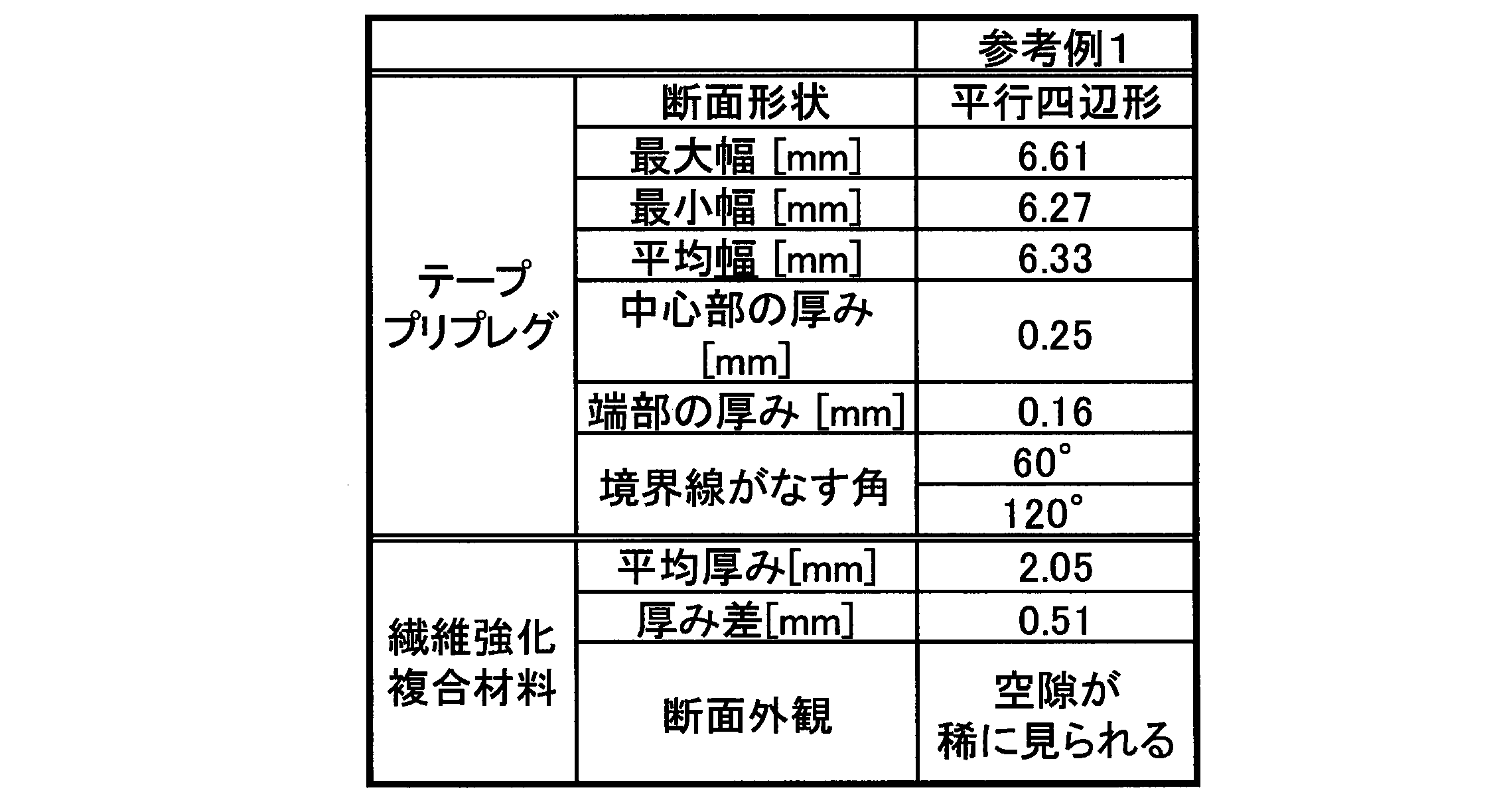
以上の結果から明らかなように、テーププリプレグの強化繊維束の配向方向の垂直断面が幅方向の端部から幅方向の中心方向にむかって連続的に厚みが増加する部位を有し、前記垂直断面の上辺と下辺が平行な直線部分を有し、前記直線部分が前記中心位置を含む実施例は、繊維強化複合材料の厚み精度、外観、機械強度に優れていた。
一方、前記垂直断面の形状が実質的に長方形である比較例1は、繊維強化複合材料の表面に繊維と樹脂の欠けた部分が見られ、その部分は窪みとなっていた。さらには機械強度も劣る結果となった。参考例1の平行四辺形の場合は、側面が型方向に露出している側(型とプリプレグとの接着面側において、プリプレグの底辺と斜辺が鈍角となる側)に第二のテープを重ねて配置し押圧が十分でない場合、内部に空隙ができる場合がある。
一方、前記垂直断面の形状が実質的に長方形である比較例1は、繊維強化複合材料の表面に繊維と樹脂の欠けた部分が見られ、その部分は窪みとなっていた。さらには機械強度も劣る結果となった。参考例1の平行四辺形の場合は、側面が型方向に露出している側(型とプリプレグとの接着面側において、プリプレグの底辺と斜辺が鈍角となる側)に第二のテープを重ねて配置し押圧が十分でない場合、内部に空隙ができる場合がある。
本発明の繊維強化複合材料用テーププリプレグ、及び前記テーププリプレグから得られる繊維強化複合材料は、航空機部材、自動車部材、自転車部材、スポーツ用品部材、鉄道車両部材、船舶部材、建築部材、オイルライザ等に好適に用いられ、特に高い耐熱性や機械特性が要求される航空機部材、自動車部材、自転車部材に好適に用いられる。
1 テーププリプレグ
1a 下辺(下辺を含む面)
1b 上辺(上辺を含む面)
2 テーププリプレグ
2a 下辺(下辺を含む面)
2b 上辺(上辺を含む面)
4 溝部
5 溝ロール
S1 幅
S2 幅
W 金型
Wa 上面
T1 最端部とプリプレグ幅方向における境界線の凹凸のうち最もプリプレグ中心と反対方向に突出した凸部の頂点とを結ぶ直線
T2 最端部とプリプレグ厚さ方向における境界線の凹凸のうち最もプリプレグ中心と反対方向に突出した凸部の頂点とを結ぶ直線
1a 下辺(下辺を含む面)
1b 上辺(上辺を含む面)
2 テーププリプレグ
2a 下辺(下辺を含む面)
2b 上辺(上辺を含む面)
4 溝部
5 溝ロール
S1 幅
S2 幅
W 金型
Wa 上面
T1 最端部とプリプレグ幅方向における境界線の凹凸のうち最もプリプレグ中心と反対方向に突出した凸部の頂点とを結ぶ直線
T2 最端部とプリプレグ厚さ方向における境界線の凹凸のうち最もプリプレグ中心と反対方向に突出した凸部の頂点とを結ぶ直線
Claims (14)
- 強化繊維を一方向に引き揃えた強化繊維束に樹脂が含浸したテーププリプレグであって、
前記強化繊維束の配向方向の垂直断面が、幅方向の一方の端部及び他方の端部から幅方向の中心にむかって連続的に厚みが増加する部位を有し、前記垂直断面の厚さ方向におけるいずれか一方の境界線と幅方向における境界線のなす角がいずれも鋭角である、テーププリプレグ。 - 前記垂直断面の厚さ方向における境界線である上辺と下辺の少なくとも一部が互いに平行な直線部分を有し、前記鋭角が40°~85°である、請求項1に記載のテーププリプレグ。
- 前記樹脂の粘度が30000Pa・s以上である、請求項1又は2に記載のテーププリプレグ。
- 前記垂直断面が台形形状又はドーム形状である、請求項1に記載のテーププリプレグ。
- 前記強化繊維束が炭素繊維束である、請求項1又は2に記載のテーププリプレグ。
- 前記樹脂がエポキシ樹脂を含む、請求項1から3のいずれか1項に記載のテーププリプレグ。
- 請求項1から4のいずれか1項に記載のテーププリプレグが加熱されて硬化した、繊維強化複合材料。
- 請求項1から4のいずれか1項に記載のテーププリプレグの複数を、前記強化繊維束の配向方向を揃えて互いに隣接するように配置し、加熱及び加圧することを含む、繊維強化複合材料の製造方法であって、
前記配置の際、第一のテーププリプレグの幅方向の端部と、第二のテーププリプレグの幅方向の端部とが、厚み方向に見て互いに重なるように配置する、繊維強化複合材料の製造方法。 - 強化繊維を一方向に引き揃えた強化繊維束に樹脂が含浸したテーププリプレグであって、前記強化繊維束の配向方向の垂直断面が、幅方向の一方の端部及び他方の端部から幅方向の中心にむかって連続的に厚みが増加する部位を有し、前記テーププリプレグが離型シートを含む、テーププリプレグ。
- 前記垂直断面の上辺と下辺の長さが異なっており、短い方の辺側のテーププリプレグ表面に前記離型シートが配置されている、請求項9に記載のテーププリプレグ。
- 強化繊維を一方向に引き揃えた強化繊維束に樹脂が含浸したテーププリプレグの配置方法であって、
前記テーププリプレグの前記強化繊維束の配向方向における垂直断面が、幅方向の一方の端部及び他方の端部から幅方向の中心にむかって連続的に厚みが増加する部位を有し、前記テーププリプレグを加熱して型に配置する、テーププリプレグの配置方法。 - 前記テーププリプレグの複数を、前記強化繊維束の配向方向を揃えて互いに隣接するように配置し、前記配置の際、第一のテーププリプレグの少なくとも一部と、第二のテーププリプレグの少なくとも一部とが、重なるように配置する、請求項11に記載のテーププリプレグの配置方法。
- 前記第一のテーププリプレグの前記連続的に厚みが増加する部位の少なくとも一部と、第二のテーププリプレグの前記連続的に厚みが増加する部位の少なくとも一部とが、重なるように配置する、請求項12に記載のテーププリプレグの配置方法。
- 強化繊維を一方向に引き揃えた強化繊維束に樹脂が含浸したテーププリプレグを用いる繊維強化複合材料の製造方法であって、
前記テーププリプレグの前記強化繊維束の配向方向における垂直断面が、幅方向の一方の端部及び他方の端部から幅方向の中心にむかって連続的に厚みが増加する部位を有し、前記テーププリプレグを加熱して型に配置する、繊維強化複合材料の製造方法。
Priority Applications (3)
| Application Number | Priority Date | Filing Date | Title |
|---|---|---|---|
| JP2020549463A JPWO2020067478A1 (ja) | 2018-09-27 | 2019-09-27 | テーププリプレグ、テーププリプレグの配置方法、繊維強化複合材料及び繊維強化複合材料の製造方法 |
| EP19865784.3A EP3858898A4 (en) | 2018-09-27 | 2019-09-27 | TAPE PRE-IMPREGNATE, TAPE PRE-IMPREGNATE DISPOSAL PROCESS, FIBER REINFORCEMENT COMPOSITE MATERIAL AND FIBER REINFORCEMENT COMPOSITE MATERIAL PRODUCTION PROCESS |
| US17/212,012 US20210206929A1 (en) | 2018-09-27 | 2021-03-25 | Tape Prepreg, Tape Prepreg Disposition Method, Fiber-Reinforcement Composite Material, Fiber-Reinforcement Composite Material Manufacturing Method |
Applications Claiming Priority (2)
| Application Number | Priority Date | Filing Date | Title |
|---|---|---|---|
| JP2018-182019 | 2018-09-27 | ||
| JP2018182019 | 2018-09-27 |
Related Child Applications (1)
| Application Number | Title | Priority Date | Filing Date |
|---|---|---|---|
| US17/212,012 Continuation US20210206929A1 (en) | 2018-09-27 | 2021-03-25 | Tape Prepreg, Tape Prepreg Disposition Method, Fiber-Reinforcement Composite Material, Fiber-Reinforcement Composite Material Manufacturing Method |
Publications (1)
| Publication Number | Publication Date |
|---|---|
| WO2020067478A1 true WO2020067478A1 (ja) | 2020-04-02 |
Family
ID=69953550
Family Applications (1)
| Application Number | Title | Priority Date | Filing Date |
|---|---|---|---|
| PCT/JP2019/038269 Ceased WO2020067478A1 (ja) | 2018-09-27 | 2019-09-27 | テーププリプレグ、テーププリプレグの配置方法、繊維強化複合材料及び繊維強化複合材料の製造方法 |
Country Status (4)
| Country | Link |
|---|---|
| US (1) | US20210206929A1 (ja) |
| EP (1) | EP3858898A4 (ja) |
| JP (1) | JPWO2020067478A1 (ja) |
| WO (1) | WO2020067478A1 (ja) |
Cited By (1)
| Publication number | Priority date | Publication date | Assignee | Title |
|---|---|---|---|---|
| JP7760099B1 (ja) * | 2025-04-02 | 2025-10-24 | 信越ポリマー株式会社 | 熱伝導性シートの製造方法 |
Families Citing this family (1)
| Publication number | Priority date | Publication date | Assignee | Title |
|---|---|---|---|---|
| US20230249416A1 (en) * | 2022-02-04 | 2023-08-10 | Northrop Grumman Systems Corporation | Automated methods for manufacturing sheets of composite material and composite structures, pattern preparation and forming systems, and sheets of composite material |
Citations (10)
| Publication number | Priority date | Publication date | Assignee | Title |
|---|---|---|---|---|
| JPS63193811A (ja) * | 1987-02-06 | 1988-08-11 | Jitensha Sangyo Shinko Kyokai | 炭素繊維強化樹脂製変形パイプ類の製造方法 |
| JPH0462142A (ja) | 1990-06-27 | 1992-02-27 | Kawasaki Heavy Ind Ltd | ロービング材自動積層装置 |
| JPH05200898A (ja) | 1992-01-28 | 1993-08-10 | Toshiba Mach Co Ltd | プリプレグの積層装置 |
| JP2003147100A (ja) * | 2001-11-14 | 2003-05-21 | Nitto Technos Kk | テープ状プリプレグ |
| JP2004043653A (ja) | 2002-07-12 | 2004-02-12 | Toray Ind Inc | スリットテーププリプレグ、およびその成形品 |
| JP2004314550A (ja) * | 2003-04-18 | 2004-11-11 | Toyota Industries Corp | Frp製パイプ及びフィラメントワインディング装置 |
| JP2011144840A (ja) * | 2010-01-12 | 2011-07-28 | Toyota Motor Corp | 圧力容器 |
| JP2012140997A (ja) * | 2010-12-28 | 2012-07-26 | Toyota Motor Corp | 圧力容器の製造方法 |
| JP2013049795A (ja) * | 2011-08-31 | 2013-03-14 | Toyobo Co Ltd | 炭素長繊維強化ポリプロピレン成形品 |
| WO2017104823A1 (ja) * | 2015-12-16 | 2017-06-22 | 三菱ケミカル株式会社 | プリプレグテープ及びその利用 |
Family Cites Families (5)
| Publication number | Priority date | Publication date | Assignee | Title |
|---|---|---|---|---|
| US4361533A (en) * | 1980-11-17 | 1982-11-30 | Amf Incorporated | Method for making racket frames |
| JPH0525615U (ja) * | 1991-09-12 | 1993-04-02 | 古河電気工業株式会社 | 樹脂含浸繊維テープ |
| JP2001040119A (ja) * | 1999-05-26 | 2001-02-13 | Toray Ind Inc | トウプリプレグ及びその製造方法 |
| US7469735B2 (en) * | 2005-08-03 | 2008-12-30 | The Boeing Corporation | Composite structural element fabricating device and method |
| EP3556800A4 (en) * | 2016-12-15 | 2020-08-19 | Toray Industries, Inc. | FIBER REINFORCED PREPREGNE, TAPE AND WOUND BODY OF FIBER REINFORCED PREPREGNE, AND PROCESS FOR THE PRODUCTION OF FIBER REINFORCED PREPREGNE AND TAPE OF FIBER REINFORCED PREPREGNATE |
-
2019
- 2019-09-27 JP JP2020549463A patent/JPWO2020067478A1/ja active Pending
- 2019-09-27 EP EP19865784.3A patent/EP3858898A4/en not_active Withdrawn
- 2019-09-27 WO PCT/JP2019/038269 patent/WO2020067478A1/ja not_active Ceased
-
2021
- 2021-03-25 US US17/212,012 patent/US20210206929A1/en not_active Abandoned
Patent Citations (10)
| Publication number | Priority date | Publication date | Assignee | Title |
|---|---|---|---|---|
| JPS63193811A (ja) * | 1987-02-06 | 1988-08-11 | Jitensha Sangyo Shinko Kyokai | 炭素繊維強化樹脂製変形パイプ類の製造方法 |
| JPH0462142A (ja) | 1990-06-27 | 1992-02-27 | Kawasaki Heavy Ind Ltd | ロービング材自動積層装置 |
| JPH05200898A (ja) | 1992-01-28 | 1993-08-10 | Toshiba Mach Co Ltd | プリプレグの積層装置 |
| JP2003147100A (ja) * | 2001-11-14 | 2003-05-21 | Nitto Technos Kk | テープ状プリプレグ |
| JP2004043653A (ja) | 2002-07-12 | 2004-02-12 | Toray Ind Inc | スリットテーププリプレグ、およびその成形品 |
| JP2004314550A (ja) * | 2003-04-18 | 2004-11-11 | Toyota Industries Corp | Frp製パイプ及びフィラメントワインディング装置 |
| JP2011144840A (ja) * | 2010-01-12 | 2011-07-28 | Toyota Motor Corp | 圧力容器 |
| JP2012140997A (ja) * | 2010-12-28 | 2012-07-26 | Toyota Motor Corp | 圧力容器の製造方法 |
| JP2013049795A (ja) * | 2011-08-31 | 2013-03-14 | Toyobo Co Ltd | 炭素長繊維強化ポリプロピレン成形品 |
| WO2017104823A1 (ja) * | 2015-12-16 | 2017-06-22 | 三菱ケミカル株式会社 | プリプレグテープ及びその利用 |
Non-Patent Citations (1)
| Title |
|---|
| See also references of EP3858898A4 |
Cited By (1)
| Publication number | Priority date | Publication date | Assignee | Title |
|---|---|---|---|---|
| JP7760099B1 (ja) * | 2025-04-02 | 2025-10-24 | 信越ポリマー株式会社 | 熱伝導性シートの製造方法 |
Also Published As
| Publication number | Publication date |
|---|---|
| US20210206929A1 (en) | 2021-07-08 |
| EP3858898A4 (en) | 2021-11-24 |
| JPWO2020067478A1 (ja) | 2021-08-30 |
| EP3858898A1 (en) | 2021-08-04 |
Similar Documents
| Publication | Publication Date | Title |
|---|---|---|
| US10808091B2 (en) | Notched pre-preg and notched pre-preg sheet | |
| JP5223354B2 (ja) | 切込プリプレグ基材、積層基材、繊維強化プラスチック、および切込プリプレグ基材の製造方法 | |
| US8354156B2 (en) | Prepreg base material, layered base material, fiber-reinforced plastic, process for producing prepreg base material, and process for producing fiber-reinforced plastic | |
| US11787150B2 (en) | Prepreg sheet and manufacturing method therefor, fiber-reinforced composite material molded article and manufacturing method therefor, and method for manufacturing preform | |
| US8361265B2 (en) | Process for producing composite prepreg base, layered base, and fiber-reinforced plastic | |
| JP6962191B2 (ja) | 繊維強化プラスチックの製造方法および繊維強化プラスチック | |
| JP2008207545A (ja) | 切込プリプレグ基材、複合切込プリプレグ基材、積層基材、繊維強化プラスチック、および切込プリプレグ基材の製造方法 | |
| JP5572947B2 (ja) | 成形材料、および、繊維強化プラスチック、ならびに、これらの製造方法 | |
| CN108350201B (zh) | 切口预浸料坯、正交铺设层叠体及切口预浸料坯的制造方法 | |
| JP2008207544A5 (ja) | ||
| JP5353099B2 (ja) | 繊維強化プラスチックの製造方法 | |
| JPWO2018003694A1 (ja) | プリプレグおよびその製造方法 | |
| JP2010023359A (ja) | 積層体の製造方法 | |
| JP2010030193A (ja) | 繊維強化プラスチックの製造方法 | |
| JP2010018723A (ja) | 切込プリプレグ基材、プリプレグ積層体、および繊維強化プラスチック | |
| US20210206929A1 (en) | Tape Prepreg, Tape Prepreg Disposition Method, Fiber-Reinforcement Composite Material, Fiber-Reinforcement Composite Material Manufacturing Method | |
| JP2008208343A (ja) | 切込プリプレグ基材、積層基材、繊維強化プラスチック、および切込プリプレグ基材の製造方法 | |
| WO2018174217A1 (ja) | 自己接着性プリプレグ、及びその製造方法 | |
| TWI888608B (zh) | 纖維強化塑膠及纖維強化塑膠之製造方法 | |
| US12508779B2 (en) | Ultra-thin pre-preg sheets and composite materials thereof | |
| JP2010195844A (ja) | 部分含浸プリプレグ及びその製造方法並びにそれを用いた繊維強化複合材料の製造方法 | |
| JP2004043653A (ja) | スリットテーププリプレグ、およびその成形品 | |
| JP2007146151A (ja) | プリプレグ基材、積層基材、繊維強化プラスチック | |
| JP7088433B1 (ja) | プリプレグ、成形体および一体化成形体 |
Legal Events
| Date | Code | Title | Description |
|---|---|---|---|
| 121 | Ep: the epo has been informed by wipo that ep was designated in this application |
Ref document number: 19865784 Country of ref document: EP Kind code of ref document: A1 |
|
| ENP | Entry into the national phase |
Ref document number: 2020549463 Country of ref document: JP Kind code of ref document: A |
|
| NENP | Non-entry into the national phase |
Ref country code: DE |
|
| ENP | Entry into the national phase |
Ref document number: 2019865784 Country of ref document: EP Effective date: 20210428 |