WO2020067480A1 - Groupe de particules composites, groupe de particules de matériau actif d'électrode négative, électrode négative, batterie et particules composites ayant des parties convexes exposées contenues dans un groupe de particules composites - Google Patents
Groupe de particules composites, groupe de particules de matériau actif d'électrode négative, électrode négative, batterie et particules composites ayant des parties convexes exposées contenues dans un groupe de particules composites Download PDFInfo
- Publication number
- WO2020067480A1 WO2020067480A1 PCT/JP2019/038275 JP2019038275W WO2020067480A1 WO 2020067480 A1 WO2020067480 A1 WO 2020067480A1 JP 2019038275 W JP2019038275 W JP 2019038275W WO 2020067480 A1 WO2020067480 A1 WO 2020067480A1
- Authority
- WO
- WIPO (PCT)
- Prior art keywords
- active material
- particles
- composite
- particle group
- negative electrode
- Prior art date
- Legal status (The legal status is an assumption and is not a legal conclusion. Google has not performed a legal analysis and makes no representation as to the accuracy of the status listed.)
- Ceased
Links
Images





Classifications
-
- H—ELECTRICITY
- H01—ELECTRIC ELEMENTS
- H01M—PROCESSES OR MEANS, e.g. BATTERIES, FOR THE DIRECT CONVERSION OF CHEMICAL ENERGY INTO ELECTRICAL ENERGY
- H01M4/00—Electrodes
- H01M4/02—Electrodes composed of, or comprising, active material
- H01M4/36—Selection of substances as active materials, active masses, active liquids
-
- H—ELECTRICITY
- H01—ELECTRIC ELEMENTS
- H01M—PROCESSES OR MEANS, e.g. BATTERIES, FOR THE DIRECT CONVERSION OF CHEMICAL ENERGY INTO ELECTRICAL ENERGY
- H01M4/00—Electrodes
- H01M4/02—Electrodes composed of, or comprising, active material
- H01M4/36—Selection of substances as active materials, active masses, active liquids
- H01M4/38—Selection of substances as active materials, active masses, active liquids of elements or alloys
-
- Y—GENERAL TAGGING OF NEW TECHNOLOGICAL DEVELOPMENTS; GENERAL TAGGING OF CROSS-SECTIONAL TECHNOLOGIES SPANNING OVER SEVERAL SECTIONS OF THE IPC; TECHNICAL SUBJECTS COVERED BY FORMER USPC CROSS-REFERENCE ART COLLECTIONS [XRACs] AND DIGESTS
- Y02—TECHNOLOGIES OR APPLICATIONS FOR MITIGATION OR ADAPTATION AGAINST CLIMATE CHANGE
- Y02E—REDUCTION OF GREENHOUSE GAS [GHG] EMISSIONS, RELATED TO ENERGY GENERATION, TRANSMISSION OR DISTRIBUTION
- Y02E60/00—Enabling technologies; Technologies with a potential or indirect contribution to GHG emissions mitigation
- Y02E60/10—Energy storage using batteries
Definitions
- the present invention relates to a composite particle group represented by a lithium secondary battery, which can be used as a negative electrode active material particle group for use in a non-aqueous electrolyte secondary battery, and more specifically, a composite particle group, a negative electrode active material particle group, and a negative electrode. , A battery, and composite particles having a convex portion exposed in the composite particle group.
- Non-aqueous electrolyte secondary batteries represented by lithium ion batteries are used in these small electronic devices.
- non-aqueous electrolyte secondary batteries are required to have improved charge / discharge capacity and improved rapid charging performance.
- Patent Document 1 WO 2015/041186 (Patent Document 1), WO 2006/075552 (Patent Document 2), JP 2016-162548 (Patent Document 3), JP 2008-235252 (Patent Document 4) ), JP-A-2008-159446 (Patent Document 5), JP-A-2018-73611 (Patent Document 6), JP-A-2001-68096 (Patent Document 7), and JP-A-2016-154061 (Patent Document 5).
- Reference 8) and Japanese Patent Application Laid-Open No. 2013-69564 propose electrode active material particles coated with a coating material in order to enhance battery performance.
- the coating active material for a lithium ion battery disclosed in Patent Literature 1 at least a part of the surface of the battery active material is coated with a coating agent containing a coating resin and a conductive auxiliary.
- the method for producing a battery active material in this document includes a step of mechanically coating the battery active material with a coating resin and a conductive additive.
- the ratio (D2 / D1) of the average particle diameter D2 ( ⁇ m) of the coating resin to the average particle diameter D1 ( ⁇ m) of the battery active material is 1 / or less.
- the ratio (D3 / D1) of the average particle diameter D3 ( ⁇ m) of the conductive additive to the average particle diameter D1 ( ⁇ m) of the battery active material is 1/10 or less.
- Patent Literature 1 describes that the conductivity of the coating active material for a lithium ion battery having the above-described configuration is increased.
- the negative electrode material for a lithium secondary battery disclosed in Patent Document 2 is one of an A phase mainly composed of silicon, and a mixed phase of a B phase composed of an intermetallic compound of a transition metal element and silicon and an A phase. Including.
- the A phase and the mixed phase are each a base material particle that is either microcrystalline or amorphous, a carbon material attached to a part of the surface of the base material particle, and a carbon material of the surface of the base material particle. And a film containing silicon oxide formed on the surface other than the surface on which silicon is adhered.
- Patent Literature 2 describes that the negative electrode material for a lithium secondary battery having the above structure can increase conductivity and reduce irreversible capacity.
- the electrode active material proposed in Patent Document 3 is an electrode active material coated with a carbonaceous material.
- the carbonaceous materials are carbon black and hydrocarbons, and the carbon black has a ratio “PPA / d” of the number PPA (number) of primary particles forming the aggregate thereof to the primary particle size d (nm) of 8 or more. It is.
- Patent Literature 3 describes that the electrode active material having the above-described configuration increases conductivity.
- the active material particles for an electrode disclosed in Patent Document 4 include an active material main body and a conductive auxiliary having electron conductivity that partially covers the surface of the active material main body. On the surface of the active material main body, a projection made of a conductive additive is formed. The height of the protrusion from the surface of the active material body is 5 to 30% of the particle diameter of the active material body.
- Patent Literature 4 describes that the active material particles for an electrode having the above-described configuration enhance the rapid charging performance.
- the active material particles for an electrode disclosed in Patent Document 5 include an active material main body and a conductive auxiliary having electron conductivity that partially covers the surface of the active material main body.
- the active material particles for an electrode have a continuous layer made of a conductive additive that covers 10 to 80% of the surface of the active material body.
- Patent Literature 5 describes that the active material particles for an electrode having the above-described structure enhance the rapid charging performance.
- the silicon-containing alloy disclosed in Patent Document 6 is coated with a carbon coating layer formed of a carbon-based material.
- the negative electrode for an electric device proposed in this document includes a silicon-containing alloy coated with the carbon coating layer, a conductive auxiliary for a negative electrode, and a binder for a negative electrode.
- the ratio of the specific surface area of the carbon-based material to the specific surface area of the conductive additive for the negative electrode is 7 or more.
- Patent Literature 6 describes that the charge / discharge efficiency and cycle durability of the negative electrode having the above-described configuration are improved.
- Patent Document 7 proposes a negative electrode active material for a non-aqueous electrolyte secondary battery comprising composite particles.
- the composite particles are a phase that occludes lithium containing at least Sn as a constituent element, and an active material particle including a phase that does not occlude lithium, and a conductive material that covers a part or the entire surface of the active material particles. Consists of In the composite particles having the above-described configuration, even if the expansion and contraction accompanying the electrochemical occlusion and release of lithium are repeated, miniaturization hardly occurs. Therefore, Patent Document 7 describes that the contact between the active material particles and the conductive agent can be maintained and the charge / discharge cycle life characteristics can be improved.
- Patent Document 8 includes graphite that is coated with amorphous carbon and is not flake-like. Patent Literature 8 describes that the negative electrode active material having the above configuration can prevent the graphite and the electrolytic solution from reacting when the battery is charged and discharged.
- the electrode material of Patent Document 9 is formed of an aggregate formed by agglomerating electrode active material particles having a carbonaceous film formed on the surface.
- the average particle size of the aggregate is 1.0 ⁇ m or more and 100 ⁇ m or less.
- the volume density of the aggregate is 50% by volume or more and 80% by volume or less of the volume density when the aggregate is made solid.
- the pore distribution of the pores inherent in the aggregate is monomodal, and the average pore diameter in the above pore distribution is 0.3 ⁇ m or less.
- Patent Document 9 describes that with the above-described configuration, unevenness in the amount of carbonaceous film carried is small and it is possible to improve electronic conductivity.
- High initial charge / discharge efficiency is required as an index of excellent charge / discharge efficiency.
- the initial charge / discharge efficiency is lower than the charge / discharge efficiency for the second and subsequent times. The reason why the initial charge / discharge efficiency is low is considered to be due to the reaction between the electrode surface and the electrolytic solution. If the initial charge / discharge efficiency is low, the charge / discharge efficiency is unlikely to increase when charge / discharge is repeated thereafter. If the charge / discharge efficiency is high from the first time, high charge / discharge efficiency can be maintained even if charge / discharge is repeated thereafter. For the above reasons, high initial charge / discharge efficiency is required.
- Patent Document 2 considers a decomposition reaction between an electrode active material and an electrolytic solution.
- a film containing silicon oxide is formed on the surface of the electrode active material.
- the conductivity of silicon oxide is low. Therefore, when a silicon oxide film is formed on the surface of the electrode active material, the decomposition reaction of the electrolytic solution is suppressed, but the conductivity may be low in some cases. If the conductivity is low, the quick charge performance is reduced.
- the purpose of the present disclosure is to achieve both excellent initial charge and discharge efficiency and excellent rapid charging performance, composite particles, negative electrode active material particles, negative electrode, battery, and convex exposed composite particles contained in the composite particles. It is to provide.
- Composite particles according to the present disclosure With multiple composite particles, The composite particles, Active material particles containing a metal active material that occludes and / or releases metal ions, An amorphous carbon coating made of amorphous carbon, which covers the surface of the active material particles,
- the plurality of composite particles have a plurality of protrusions, In the plurality of composite particles having a median diameter (d50) or more, the average coverage of the amorphous carbon coating on the surface of the active material particles is 50 to 90 area%; In the composite particles, when an area where the surface of the active material particles is exposed by 1 ⁇ m 2 or more is defined as an exposed area, a plurality of the composite particles having the particle diameter equal to or more than the median diameter (d50) are used.
- the number density of the exposed region with respect to the total surface area of the composite particles is 0.0010 to 0.0500 particles / ⁇ m 2 .
- Negative electrode active material particles Comprising a plurality of negative electrode active material materials, The plurality of negative electrode active material materials, Including the composite particle group described above, The ratio of the composite particle group is 70% or more among a plurality of the negative electrode active material materials having a particle diameter of a median diameter (d50) or more.
- the negative electrode according to the present disclosure includes: A thin-film or plate-like active material supporting member, A negative electrode mixture layer formed on the surface of the active material support member, The negative electrode mixture layer, The negative electrode active material particles, A binder in which the negative electrode active material particles are dispersed.
- the battery according to the present disclosure includes: The negative electrode, A positive electrode, A separator, And an electrolyte.
- Convex exposed composite particles Active material particles containing a metal active material that occludes and / or releases metal ions, An amorphous carbon coating made of amorphous carbon, which covers the surface of the active material particles, A coverage of the amorphous carbon coating on the surface of the active material particles is 50 to 90 area%;
- the convex portion-exposed composite particles have a plurality of convex portions, In the plurality of protrusions, there is at least one or more exposed areas where the surface of the active material particles is exposed by 1 ⁇ m 2 or more.
- the composite particle group, the negative electrode active material particle group, the negative electrode, the battery, and the convex portion exposed composite particles according to the present disclosure can achieve both excellent rapid charging performance and excellent initial charge / discharge efficiency.
- FIG. 1 is a diagram showing the relationship between the average coverage of the amorphous carbon film and the initial charge / discharge efficiency in the composite particle group.
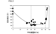
- FIG. 2 is a diagram showing the relationship between the average coverage of the amorphous carbon coating in the composite particle group and the reaction resistance, which is an index of the rapid charging performance.
- FIG. 3 is a perspective view of the convex-part exposed composite particles of the present embodiment.
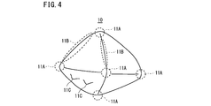
- FIG. 4 is a perspective view of the active material particles in FIG.
- FIG. 5 is an image of a secondary electron image of the active material particles of the present embodiment at a magnification of 5000 using a scanning electron microscope.
- FIG. 6 is an SEM image of the composite particles of the present embodiment.
- FIG. 7 is a quaternized image of the SEM image of FIG. FIG.
- FIG. 8 is a SEM image of the composite particle group of the present embodiment at a magnification of 1000 times.
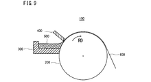
- FIG. 9 is a schematic view of an apparatus for producing a metal active material of active material particles according to the present embodiment.
- FIG. 10 shows, under the production conditions of the composite particle group according to the present embodiment, the peripheral speed Y (m / sec) of the rotor of the dry particle composite apparatus, the processing time X (minute) in the composite processing step, and the median diameter.
- D50 The average coverage of the amorphous carbon coating of a plurality of composite particles having a particle size of not less than 50 to 90%, and the number density of the exposed region is 0.0010 to 0.0500 particles / ⁇ m 2.
- FIG. 4 is a diagram showing a relationship with whether or not the composite particle group of the present embodiment was produced.
- the present inventors have studied a composite particle group that achieves both rapid charging performance and initial charge / discharge efficiency. As a result, the present inventors have obtained the following findings.
- the present inventors first studied to increase the initial charge / discharge efficiency.
- the decomposition reaction of the electrolytic solution caused by the reaction between the active material particles containing the metal active material and the electrolytic solution may be suppressed. If the decomposition reaction of the electrolytic solution due to the reaction between the active material particles and the electrolytic solution is suppressed, the decomposition products generated by the decomposition reaction can be suppressed from being deposited on the surface of the active material particles, and the decomposition gas is generated. Can be suppressed. As a result, the initial charge / discharge efficiency increases.
- the present inventors have proposed to coat the active material particles containing the metal active material with an amorphous carbon film made of amorphous carbon in order to suppress the reaction between the active material particles and the electrolytic solution. Thought.
- amorphous carbon is also referred to as amorphous carbon, and means a carbon having a structure in which fine crystals are randomly connected and having no regular crystal structure.
- amorphous carbon In amorphous carbon, the development of crystallites called the hexagonal mesh of carbon is smaller than in graphite. In the case of amorphous carbon, the reactivity of the electrolyte at the hexagonal mesh surface edge is lower than that of graphite, and the side reaction (irreversible capacity) associated with the decomposition of the electrolyte is smaller than that of graphite. Therefore, the charge acceptance of the metal ions represented by the lithium ions is higher in the amorphous carbon film than in the graphite film.
- the active material particles covered with the amorphous carbon film contain a metal active material.
- the “metal active material” is a substance that stores and / or releases metal ions.
- the metal active material contains at least 80 at% in total of one or more selected from the group consisting of metal elements and metalloid elements.
- the metal element is at least one selected from the group consisting of copper (Cu), tin (Sn), aluminum (Al), and zinc (Zn).
- the metalloid element is, for example, silicon (Si).
- the metal active material may be a simple metal, an alloy, a metal oxide, or an intermetallic compound.
- the intermetallic compound is, for example, Cu 6 Sn 5 , Cu 3 Sn, or the like.
- the metal active material is composed of one or more selected from the group consisting of a metal, an alloy, an intermetallic compound, and a metal oxide, and the balance is composed of impurities.
- Metal ions are, for example, lithium ions, magnesium ions, sodium ions and the like. Preferred metal ions are lithium ions.
- a particle comprising an active material particle containing a metal active material and an amorphous carbon coating covering the surface of the active material particle is defined as a “composite particle”.
- the composite particle group including a plurality of composite particles it is considered that the initial charge / discharge efficiency is increased based on the above-described mechanism.
- the present inventors have found that in the above-described composite particle group, although the initial charge / discharge efficiency is increased, the rapid charging performance may be significantly reduced in some cases. Then, the present inventors investigated and examined the cause of the deterioration of the rapid charging performance. As a result, the following items were considered as factors that deteriorate the rapid charging performance.
- the present inventors considered that a part of the amorphous carbon coating covering the surface of the active material particles was intentionally peeled off to expose a part of the surface of the active material particles. If the surface of the active material particles is covered with the amorphous carbon film and a part of the surface of the active material particles is exposed, the contact between the active material particles and the electrolyte is suppressed by the amorphous carbon film.
- the metal ions easily enter and exit the active material particles from the region where the active material particles are exposed. If the metal ions can enter and exit, alloying of the metal ions with the metal active material in the active material particles becomes possible. Therefore, it is considered that quick charging performance is improved.
- the present inventors studied a method of adjusting the coverage of the amorphous carbon film on the surface of the active material particles.
- the shape of the active material particles is not spherical, but has a shape having a plurality of convex portions
- the amorphous carbon coating once coated on the plurality of convex portions can be peeled off. It was thought that the exposed region could be formed.
- the plurality of protrusions of the active material particles may be, for example, corners or ridges in the particle shape.
- the convex portion may be a convex portion other than the corner portion and the ridge line portion of the particle.
- the present inventors used an active material particle having a plurality of projections to coat the surface of the active material particle with an amorphous carbon coating, and further coated the amorphous carbon coating.
- a plurality of types of composite particle groups having adjusted ratios were produced.
- the relationship between the average coverage of the amorphous carbon coating in a plurality of composite particles having a median diameter (d50) or more among the composite particle group, and the initial charge / discharge efficiency and rapid charging performance was investigated. .
- FIG. 1 shows a composite particle group including a plurality of composite particles each including an active material particle and an amorphous carbon film coated on the surface of the active material particle, among a plurality of composite particles having a median diameter (d50) or more.
- FIG. 3 is a diagram showing a relationship between the average coverage of the amorphous carbon film with particles and the initial charge / discharge efficiency.
- FIG. 2 is a diagram showing the relationship between the average coverage of the amorphous carbon film and the rapid charging performance in the above-described composite particle group.
- the reaction resistance ( ⁇ ) corresponding to the vertical axis in FIG. 2 is an index of the quick charging performance. The lower the reaction resistance, the higher the rapid charging performance.
- a composite particle group composed of a plurality of composite particles in which an active material particle having a plurality of convex portions is coated with an amorphous carbon film has a median diameter (d50) or more. It has been found that, when the average coverage of the amorphous carbon coating of a plurality of composite particles is 50 to 90 area%, not only excellent initial charge / discharge efficiency can be obtained, but also rapid charging performance is enhanced.
- the average coverage of the amorphous carbon coating of a plurality of composite particles having a particle diameter equal to or larger than the median diameter (d50) is 50 to 90 area%, the rapid charging performance may still be low.
- the inventors further studied.
- the composite particles not only the average coverage of the amorphous carbon film with a plurality of composite particles having a median diameter (d50) or more than 50 to 90 area%, but also the It has been found that it is important that at least one exposed region in which the surface of the active material particles is not less than 1 ⁇ m 2 is not coated with the carbonaceous film.
- the average coverage of the amorphous carbon coating in the composite particles having a particle diameter equal to or larger than the median diameter (d50) is 50 to 90% by area, and the total surface area of the composite particles is It has been found that, when the number density of the exposed region is 0.0010 to 0.0500 / ⁇ m 2 , it is possible to achieve both excellent initial charge / discharge efficiency and excellent rapid charging performance.
- the composite particle group, the negative electrode active material particle group, the negative electrode, the battery, and the convex exposed composite particles of the present embodiment completed based on the above findings have the following configurations.
- a composite particle group With multiple composite particles, The composite particles, Active material particles containing a metal active material that occludes and / or releases metal ions, An amorphous carbon coating made of amorphous carbon, which covers the surface of the active material particles,
- the plurality of composite particles have a plurality of protrusions, In the plurality of composite particles having a median diameter (d50) or more, the average coverage of the amorphous carbon coating on the surface of the active material particles is 50 to 90 area%; In the composite particles, when an area where the surface of the active material particles is exposed by 1 ⁇ m 2 or more is defined as an exposed area, a plurality of the composite particles having the particle diameter equal to or more than the median diameter (d50) are used. The number density of the exposed region with respect to the total surface area of the composite particles is 0.0010 to 0.0500 particles / ⁇ m 2 .
- Composite particle group Composite particle group.
- a composite particle group according to [1] The Vickers hardness of the active material particles is HV 20 to 500, Composite particle group.
- the composite particle group according to any one of [1] to [3],
- the metal active material is Containing at least one selected from the group consisting of Cu, Sn, and Si, Composite particle group.
- the composite particle group according to [4] The metal active material is Sn: 10 to 40 at%; Cu: 50 to 90 at%; Composite particle group.
- the composite particle group according to [5], The metal active material further comprises: Sn: 10 to 35 at%; Ti: 9 at% or less, V: 49 at% or less, Cr: 49 at% or less, Mn: 9 at% or less, Fe: 49 at% or less, Co: 49 at% or less, Ni: 9 at% or less, Zn: 29 at% or less, Al: 49 at% or less, Si: 49 at% or less, B: 5 at% or less, and C: at least one selected from the group consisting of 5 at% or less; The remainder consists of Cu and impurities, Composite particle group.
- the composite particle group according to any one of [1] to [6],
- the plurality of composite particles include a plurality of convex exposed composite particles,
- the convex portion-exposed composite particles have a plurality of convex portions,
- the coverage of the amorphous carbon film is 50 to 90 area%, and the surface of the active material particles is exposed to 1 ⁇ m 2 or more in a plurality of the convexes.
- There is at least one or more exposed areas Among the plurality of composite particles having a particle diameter equal to or larger than the median diameter (d50), the number ratio of the convex-part exposed composite particles is 80% or more.
- a negative electrode active material particle group Comprising a plurality of negative electrode active material materials, The plurality of negative electrode active material materials, Comprising the composite particle group according to any one of [1] to [7], Among the negative electrode active material materials having a median diameter (d50) or more, the ratio of the composite particle group is 70% or more. Negative electrode active material particles.
- a negative electrode A thin-film or plate-like active material supporting member, A negative electrode mixture layer formed on the surface of the active material support member, The negative electrode mixture layer, A negative electrode active material particle group according to [8],
- the negative electrode active material particles include a binder dispersed therein, Negative electrode.
- the negative electrode according to [9] The negative electrode active material particle group includes the composite particle group according to any one of [1] to [7], Negative electrode.
- a negative electrode according to [9] or [10] A positive electrode, A separator, And an electrolyte, battery.
- Convex composite particles Active material particles containing a metal active material that occludes and / or releases metal ions, An amorphous carbon coating made of amorphous carbon, which covers the surface of the active material particles, A coverage of the amorphous carbon coating on the surface of the active material particles is 50 to 90 area%;
- the convex portion-exposed composite particles have a plurality of convex portions, In the plurality of projections, there is at least one or more exposed regions where the surface of the active material particles is exposed by 1 ⁇ m 2 or more. Convex exposed composite particles.
- the convex-part exposed composite particles according to [12] or [13] The metal active material is Containing at least one selected from the group consisting of Cu, Sn, and Si, Convex exposed composite particles.
- the convex-part exposed composite particles according to [14] The metal active material is Sn: 10 to 40 at%; Cu: 50 to 90 at%; Convex exposed composite particles.
- the convex-part exposed composite particles according to [15], The metal active material further comprises: Sn: 10 to 35 at%; Ti: 9 at% or less, V: 49 at% or less, Cr: 49 at% or less, Mn: 9 at% or less, Fe: 49 at% or less, Co: 49 at% or less, Ni: 9 at% or less, Zn: 29 at% or less, Al: 49 at% or less, Si: 49 at% or less, B: 5 at% or less, and C: at least one selected from the group consisting of 5 at% or less; The remainder consists of Cu and impurities, Convex exposed composite particles.
- the composite particle group of the present embodiment includes a plurality of composite particles.
- FIG. 3 is a perspective view showing an example of the composite particles.
- the composite particles 1 include active material particles 10 and an amorphous carbon coating 30.
- the amorphous carbon film 30 is a hatched area.
- the active material particles 10 contain a metal active material.
- the metal active material is a material that stores and / or releases metal ions.
- the amorphous carbon film 30 is made of amorphous carbon and covers the surface of the active material particles 10.
- FIG. 4 is a perspective view of the active material particles 10 in FIG.
- active material particles 10 are not spherical but have a shape having a plurality of convex portions 11 (11A to 11C).
- the protrusion 11 includes a corner 11A, a ridge 11B, and a protrusion 11C formed on a flat surface. In short, the protrusion 11 means a portion that protrudes outside on the surface of the active material particle 10.
- FIG. 5 is an image of a secondary electron image of the active material particles 10 of the present embodiment using a scanning electron microscope (hereinafter, also referred to as an SEM image).
- FIG. 6 is an SEM image of the composite particle 1 of the present embodiment.
- the SEM images in FIGS. 5 and 6 are images obtained by observing at a magnification of 5000.
- active material particles 10 are not spherical but have a shape having a plurality of convex portions 11.
- composite particle 1 has a plurality of convex portions 11 similarly to active material particles 10.
- the surface of the active material particles 10 is covered with a black amorphous carbon film 30 on the SEM image. Further, there is a region where a part of the surface of the active material particle 10 is exposed among the plurality of convex portions 11 of the composite particle 1. Among the exposed areas, the area where the surface of the active material particles 10 is exposed by 1 ⁇ m 2 or more is defined as an “exposed area” 20.
- the active material particles 10 and the amorphous carbon coating 30 constituting the composite particles 1 will be described in detail.
- the active material particles 10 contain a metal active material. Metal active materials occlude and / or release metal ions. Preferably, the active material particles 10 include a metal active material and impurities.
- the metal active material contains at least 80 at% in total of one or more selected from the group consisting of metal elements and metalloid elements.
- an element contained other than the metal element and the metalloid element is, for example, oxygen or carbon.
- the metal element is, for example, one or more selected from the group consisting of copper (Cu), tin (Sn), aluminum (Al), and zinc (Zn).
- the metalloid element is, for example, silicon (Si).
- the metal active material contains one or more selected from the group consisting of metals, metalloids, alloys, intermetallic compounds, and metal oxides, with the balance being impurities. More preferably, the metal active material is composed of one or more selected from the group consisting of metals, metalloids, alloys, and intermetallic compounds, with the balance being impurities.
- Metal ions are, for example, lithium ions, magnesium ions, sodium ions and the like. Preferred metal ions are lithium ions.
- the active material particles 10 may contain a substance other than the metal active material.
- the metal active material is a main component (main phase) of the active material particles 10.
- Main component means a component occupying 50% by volume or more.
- the component other than the metal active material in the active material particles 10 is, for example, carbon (graphite).
- the metal active material accounts for 90% by volume or more of the active material particles 10. More preferably, the active material particles 10 are made of a metal active material.
- the metal active material may contain impurities within a range that does not impair the gist of the present invention.
- the metal active material contains at least one selected from the group consisting of Cu, Sn and Si.
- the metal active material contains Sn, and the balance consists of Cu and impurities. More preferably, the metal active material contains 10 to 40 at% of Sn and 50 to 90 at% of Cu, with the balance being impurities.
- Sn 10 to 40 at% Tin (Sn) increases the discharge capacity per volume. If the Sn content is 10 at% or more, this effect can be obtained effectively. When the Sn content is 40 at% or less, the initial charge / discharge efficiency is further increased. Therefore, the preferred Sn content is 10 to 40 at%.
- the more preferable lower limit of the Sn content is 13 at%, more preferably 18.5 at%, and further preferably 21 at%.
- a more preferable upper limit of the Sn content is 35 at%, and further preferably 30 at%.
- Cu 50 to 90 at% Copper (Cu) enhances charge / discharge efficiency.
- Cu content is 50 at% or more, the initial charge / discharge efficiency is further increased. If the Cu content is 90 at% or less, the discharge capacity per volume increases. Therefore, the Cu content is 50 to 90 at%.
- a more preferred lower limit of the Cu content is 55 at%, and still more preferably 60 at%.
- a more preferred upper limit of the Cu content is 80 at%, and more preferably 70 at%.
- the metal active material also contains at least one selected from the group consisting of Ti, V, Cr, Mn, Fe, Co, Ni, Zn, Al, Si, B and C, and Sn, with the balance being Cu And impurities.
- the metal active material contains at least one selected from the group consisting of Ti, V, Cr, Mn, Fe, Co, Ni, Zn, Al, Si, B and C, and Sn, and the balance Cu and impurities.
- the metal active material comprises Sn: 10 to 35 at%, Ti: 9 at% or less, V: 49 at% or less, Cr: 49 at% or less, Mn: 9 at% or less, Fe: 49 at% or less, Co: selected from the group consisting of 49 at% or less, Ni: 9 at% or less, Zn: 29 at% or less, Al: 49 at% or less, Si: 49 at% or less, B: 5 at% or less, and C: 5 at% or less.
- One or more, and the balance consists of Cu and impurities.
- the preferable upper limit of the Ti content is 9 at% as described above.
- the more preferable upper limit of the Ti content is 6 at%, and more preferably 5 at%.
- a preferred lower limit of the Ti content is 0.1 at%, more preferably 0.5 at%, and still more preferably 1 at%. Ti suppresses excessive oxidation of Cu and Sn, and can further increase the initial charge / discharge efficiency.
- the preferable upper limit of the ⁇ V content is 49 at% as described above.
- a more preferred upper limit of the V content is 30 at%, more preferably 15 at%, and further preferably 10 at%.
- a preferred lower limit of the V content is 0.1 at%, more preferably 0.5 at%, and still more preferably 1 at%. V suppresses excessive oxidation of Cu and Sn, and can further increase the initial charge / discharge efficiency.
- the preferable upper limit of the Cr content is 49 at% as described above.
- a more preferred upper limit of the Cr content is 30 at%, more preferably 15 at%, and further preferably 10 at%.
- a preferred lower limit of the Cr content is 0.1 at%, more preferably 0.5 at%, and still more preferably 1 at%. Cr suppresses excessive oxidation of Cu and Sn, and can further increase the initial charge / discharge efficiency.
- the preferable upper limit of the Mn content is 9 at% as described above.
- a more preferred upper limit of the Mn content is 6 at%, and more preferably 5 at%.
- a preferred lower limit of the Mn content is 0.1 at%, more preferably 0.5 at%, and still more preferably 1 at%. Mn suppresses excessive oxidation of Cu and Sn, and can further increase the initial charge / discharge efficiency.
- the preferred upper limit of the Fe content is 49 at% as described above.
- a more preferred upper limit of the Fe content is 30 at%, more preferably 15 at%, and further preferably 10 at%.
- a preferred lower limit of the Fe content is 0.1 at%, more preferably 0.5 at%, and still more preferably 1 at%. Fe suppresses excessive oxidation of Cu and Sn, and can further increase the initial charge / discharge efficiency.
- the preferable upper limit of the Co content is 49 at% as described above.
- a more preferred upper limit of the Co content is 30 at%, more preferably 15 at%, and further preferably 10 at%.
- a preferred lower limit of the Co content is 0.1 at%, more preferably 0.5 at%, and still more preferably 1 at%. Co suppresses excessive oxidation of Cu and Sn, and can further increase the initial charge / discharge efficiency.
- the preferable upper limit of the Ni content is 9 at% as described above.
- a more preferred upper limit of the Ni content is 5 at%, and more preferably 2 at%.
- a preferred lower limit of the Ni content is 0.1 at%, more preferably 0.5 at%, and still more preferably 1 at%. Ni suppresses excessive oxidation of Cu and Sn, and can further increase the initial charge / discharge efficiency.
- the preferable upper limit of the Zn content is 29 at% as described above.
- a more preferred upper limit of the Zn content is 27 at%, and more preferably 25 at%.
- a preferred lower limit of the Zn content is 0.1 at%, more preferably 0.5 at%, and still more preferably 1 at%. Zn suppresses excessive oxidation of Cu and Sn, and can further increase the initial charge / discharge efficiency.
- a preferred upper limit of the Al content is 49 at% as described above.
- a more preferable upper limit of the Al content is 30 at%, more preferably 15 at%, and further preferably 10 at%.
- a preferred lower limit of the Al content is 0.1%, more preferably 0.5 at%, and still more preferably 1 at%. Al suppresses excessive oxidation of Cu and Sn, and can further increase the initial charge / discharge efficiency.
- the preferable upper limit of the Si content is 49 at% as described above.
- the more preferable upper limit of the Si content is 30 at%, more preferably 15 at%, and further preferably 10 at%.
- a preferred lower limit of the Si content is 0.1 at%, more preferably 0.5 at%, and still more preferably 1 at%. Si can increase the discharge capacity per volume.
- the preferable upper limit of the B content is 5 at%.
- a preferred lower limit of the B content is 0.01 at%, more preferably 0.1 at%, further preferably 0.5 at%, and further preferably 1 at%.
- B suppresses excessive oxidation of Cu and Sn, and can further increase the initial charge / discharge efficiency.
- a preferable upper limit of the ⁇ C content is 5 at%.
- a preferred lower limit of the C content is 0.01 at%, more preferably 0.1 at%, further preferably 0.5 at%, and further preferably 1 at%.
- C can reduce the volume expansion coefficient (at the time of absorbing metal ions) of the metal active material.
- the metal active material may further contain Sn and a Group 2 element and / or a rare earth element (REM) for the purpose of increasing the discharge capacity, and the balance may be made of Cu and impurities.
- Group 2 elements are, for example, magnesium (Mg), calcium (Ca) and the like.
- REM is, for example, lanthanum (La), cerium (Ce), praseodymium (Pr), neodymium (Nd), or the like.
- the Vickers hardness of the active material particles 10 is HV 20 to 500.
- the Vickers hardness of the active material particles 10 affects the coverage of the amorphous carbon film 30 covering the surface of the active material particles 10.
- the Vickers hardness of the active material particles 10 is HV20 or more, it is easy to form the active material particles 10 having the plurality of convex portions 11 when a composite particle group is manufactured by a composite process described below.
- the Vickers hardness of the active material particles 10 is HV 500 or less, the entire surface of the active material particles 10 having the plurality of convex portions 11 is coated in the case where a composite particle group is manufactured by a composite process described below.
- the amorphous carbon film 30 covering the projections 11 is easily peeled. As a result, it is easy to form at least one or more exposed regions 20 where the surfaces of the active material particles 10 are exposed to 1 ⁇ m 2 or more among the plurality of protrusions 11, and to have a plurality of particles having a median diameter (d50) or more. In the composite particles, the average coverage of the amorphous carbon coating 30 is easily set to 50 to 90 area%.
- a preferred lower limit of the Vickers hardness of the active material particles 10 is HV30, more preferably HV50, and further preferably HV80.
- the preferred upper limit of the Vickers hardness of the active material particles 10 is HV480, more preferably HV460, and still more preferably HV450.
- Vickers hardness depends on the chemical composition of the metal active material. For example, when the metal active material contains 10 to 40 at% of Sn and 50 to 90 at% of Cu, the Vickers hardness of the active material particles 10 becomes HV 20 to 500.
- the Vickers hardness of the active material particles 10 is measured by the following method.
- a liquid epoxy resin precursor, a curing agent, and a plurality of composite particles 1 are mixed to obtain a mixture.
- the curing agent may be a commercially available epoxy resin curing agent.
- the mixture is poured into a mold and cured to obtain a cured product.
- the surface of the cured product taken out of the mold (hereinafter referred to as a measurement surface) is subjected to wet polishing using a sandpaper to form a measurement surface including a cross section of the composite particle 1.
- the measurement surface including the cross section of the composite particle 1 is further subjected to mirror polishing with aluminum oxide powder.
- the particle diameter of the aluminum oxide powder is gradually reduced (for example, in the order of 0.3 ⁇ m and 0.06 ⁇ m), and the cross section of the composite particle 1 in the measurement plane is polished to be flat.
- the Vickers hardness of the cross section of the active material particles 10 among the cross sections of the composite particles 1 on the measurement surface is measured using a micro Vickers hardness meter. Specifically, the Vickers hardness is measured by using an optical microscope to position the indenter substantially at the center of the cross section of the active material particles 10. The test load is 50 gf. A diamond indenter is used as the indenter.
- the micro Vickers hardness tester is not particularly limited.
- the micro Vickers hardness tester is, for example, MVK-G2 manufactured by Akashi Seisakusho.
- the Vickers hardness of the active material particles 10 of the ten composite particles 1 in the measurement plane is measured.
- the arithmetic average of the ten Vickers hardnesses is defined as the Vickers hardness HV of the active material particles 10.
- the median diameter (d50) of the plurality of active material particles 10 constituting the composite particle group is not particularly limited.
- the median diameter (d50) of the active material particles 10 is, for example, 1 to 50 ⁇ m.
- the coverage of the amorphous carbon film 30 can be easily adjusted to 50 to 90 area%.
- the coverage of the amorphous carbon film 30 can be easily adjusted to 50% by area or more.
- a preferred lower limit of the median diameter (d50) of the active material particles 10 is 3 ⁇ m, and more preferably 5 ⁇ m.
- the preferable upper limit of the median diameter (d50) of the active material particles 10 is 45 ⁇ m, more preferably 40 ⁇ m, and further preferably 35 ⁇ m.
- the median diameter (d50) of the active material particles 10 is determined by the following method. A part of the plurality of active material particles 10 serving as a raw material of the plurality of particle groups is scooped and collected. The median diameter of the active material particles 10 is measured for the plurality of collected active material particles 10 by a laser diffraction / scattering method using a laser diffraction / scattering type particle size distribution analyzer in accordance with JIS Z 8825 (2013). d50) is measured.
- the dispersion medium in the measurement is water to which a surfactant containing an alkyl glycooxide is added by 0.1% by mass.
- the dispersion method is ultrasonic for 5 minutes.
- the particle size when the cumulative volume with respect to the volume of all particles becomes 50% (volume average particle size by laser diffraction scattering method) is defined as the average particle size of the active material particles 10 (median diameter (d50)).
- the amorphous carbon film 30 is made of amorphous carbon.
- amorphous carbon refers to carbon having a structure in which fine crystals are randomly connected and having no regular crystal structure.
- Amorphous carbon has a short-range order (several atoms to several tens of atoms) and no long-range order (several hundreds to thousands of atoms). Therefore, in amorphous carbon, the development of crystallites called a hexagonal mesh plane of carbon is smaller than that of graphite.
- the amorphous carbon film 30 has higher charge acceptability of metal ions represented by lithium ions than the graphite film.
- confirmation of the amorphous carbon film 30 is performed by the following X-ray diffraction method.
- An arbitrary part of the plurality of composite particles 1 is collected with a spoon.
- a plurality of the collected composite particles 1 are placed (deposited) on a non-reflection sample plate (a plate cut out so that a specific crystal plane of a silicon single crystal is parallel to a measurement plane).
- the surface of the deposit of the plurality of composite particles 1 is flattened with a slide glass to obtain a sample.
- the sample is set in an X-ray diffractometer and X-ray diffraction measurement is performed to obtain an X-ray diffraction profile.
- X-rays are incident on the amorphous carbon coating 30 covering the surface of the composite particle 1, and an X-ray diffraction profile of the amorphous carbon coating 30 is obtained.
- the battery is disassembled and subjected to X-ray diffraction measurement to determine the presence or absence of the amorphous carbon film 30, the following method is performed.
- the battery before charging or, in the case of the used battery, the battery after discharging is disassembled in a glove box in an argon atmosphere, and a negative electrode to which a plurality of composite particles 1 are attached is taken out from the battery.
- the removed negative electrode is wrapped in Mylar foil. Thereafter, the periphery of the Mylar foil is sealed with a thermocompression bonding machine.
- the negative electrode sealed with Myra foil is taken out of the glove box.
- the inside of the glove box is made to have an argon atmosphere using an argon gas supplied from an ultrahigh-purity argon gas cylinder having a purity of 99.9999% or more. Further, argon gas is passed through a purifier using a catalyst or the like to prevent impurities such as nitrogen from entering the system. Thus, the dew point is controlled to be ⁇ 60 ° C. or less to prevent the composite particles 1 from being deteriorated by nitrogen or moisture.
- the negative electrode is attached to a non-reflective sample plate by hair spray to prepare a sample. The sample is set on an X-ray diffractometer, and X-ray diffraction measurement of the sample is performed. In this case, X-rays are incident on the amorphous carbon coating 30 covering the surface of the composite particles 1 of the negative electrode, and an X-ray diffraction profile of the amorphous carbon coating 30 is obtained.
- the measurement conditions of the X-ray diffraction measurement for determining the amorphous carbon film 30 are as follows.
- -Equipment Rigaku SmartLab ⁇ X-ray tube: Cu-K ⁇ ray ⁇ X-ray output: 45 kV, 200 mA -Incident side monochromator: Johansson element (cuts Cu-K ⁇ 2 line and Cu-K ⁇ line)
- -Optical system Focusing method-Incident parallel slit: 5.0 degrees-Incident slit: 1/2 degree-Longitudinal slit: 10.0 mm -Light receiving slit 1: 8.0 mm -Light receiving slit 2: 13.0 mm ⁇
- Light receiving parallel slit 5.0 degrees ⁇
- Goniometer SmartLab goniometer ⁇ Distance between X-ray source and mirror: 90.0 mm ⁇ Distance between X-ray source and selected slit: 114.0 mm ⁇ X-ray source-sample distance: 30
- the X-ray analysis software is, for example, PDXL software built into Rigaku's SmartLab, but is not limited to this as long as equivalent results can be obtained. If the crystallite diameter Lc is 50 nm or less, it is determined that the coating covering the active material particles 10 is the amorphous carbon coating 30.
- the amorphous carbon film 30 is formed by performing a compounding process using a carbon source as a raw material and the active material particles 10 using a dry particle compounding apparatus described later.
- the carbon source is an organic substance.
- the organic substance serving as a carbon source is, for example, at least one selected from the group consisting of carbon black, hard carbon, soft carbon, mesoporous carbon, and activated carbon. Among these, carbon black is particularly preferred.
- Carbon black generally has a small primary particle size, and the carbon structure is crushed by a complexing process described below. Therefore, the carbon black easily coats the active material particles. Therefore, the carbon source that is the raw material of the amorphous carbon coating 30 is preferably carbon black. Carbon black is amorphous carbon. In carbon black, primary particles of several to several hundreds of nm form a structure to form secondary particles. Representative carbon blacks are conductive carbon black, acetylene black and Ketjen black. Preferably, the carbon black has a primary particle size of 5 to 200 nm. In this case, the carbon source (carbon black) easily adheres to the surface of the active material particles 10 during the complexing process.
- the specific surface area of the carbon source as the raw material of the amorphous carbon film 30 is not particularly limited.
- the specific surface area of the carbon source is, for example, 5 to 500 m 2 / g. If the specific surface area of the carbon source is 5 m 2 / g or more, the active material particles 10 can be appropriately coated. When the specific surface area of the carbon source is 500 m 2 / g or less, the coverage of the amorphous carbon film 30 is easily reduced to 90 area% or less. If the specific surface area of the carbon source exceeds 500 m 2 / g, the coverage and specific surface area of the composite particles 1 are too high depending on the conditions of the compounding treatment in the compounding treatment step described below.
- a more preferred lower limit of the specific surface area of the carbon source is 10 m 2 / g, and a more preferred upper limit is 100 m 2 / g.
- the composite particle group of the present embodiment includes a plurality of composite particles 1.
- “composed of a plurality of composite particles 1” allows the incorporation of impurities.
- a plurality of composite particles 1 account for 99% or more of the mass% of the composite particle group of the present embodiment.
- the composite particle group may include the following three types of composite particles 1. Specifically, the composite particle group includes type 1 composite particles (projection-exposed composite particles) and may include type 2 and / or type 3 composite particles.
- Type 1 convex part exposed composite particles. That is, it includes the active material particles 10 and the amorphous carbon film 30 covering the surface of the active material particles 10, the coverage of the amorphous carbon film 30 is 50 to 90 area%, and the In part 11, composite particles in which at least one or more exposed region 20 where the surface of active material particles 10 is exposed by 1 ⁇ m 2 or more is present.
- Type 2 Covers active material particles 10 and surface of active material particles 10.
- a composite particle including the amorphous carbon coating 30 and the coverage of the amorphous carbon coating 30 is less than 50 area% or more than 90 area%.
- Type 3 Active Material Particle 10 and Surface of Active Material Particle 10 And an amorphous carbon film 30 covering the active material particles, wherein the coverage of the amorphous carbon film 30 is 50 to 90 area%, but the exposed region 20 where the surface of the active material particles is 1 ⁇ m 2 or more is 1 Composite particles that never exist
- the convex-exposed composite particles are the composite particles 1 that are the main components of the composite particle group.
- the coverage of the amorphous carbon film 30 on the surface of the active material particles 10 is 50 to 90 area%.
- at least one or more exposed regions 20 where the surface of the active material particles 10 is exposed by 1 ⁇ m 2 or more among the plurality of convex portions 11 exist.
- FIG. 3 is a schematic view of a type 1 composite particle, that is, a convex exposed composite particle, among the composite particles 1. As shown in FIG.
- FIG. 6 is an SEM image of the convex-part exposed composite particles among the composite particles. 6, the white region 20 corresponds to the exposed region 20, and the black region 30 corresponds to the amorphous carbon coating 30. As is clear from FIG. 6, at least one exposed region 20 is formed on the convex portion 11.
- the main component of the composite particle group of the present embodiment is a plurality of convex portion-exposed composite particles.
- the average coverage of the amorphous carbon coating 30 on the surface of the active material particles 10 in the plurality of composite particles 1 having a median diameter (d50) or more is 50 to 50%. 90 area%.
- the number density of the exposed region 20 where the surface of the active material particles 10 is not less than 1 ⁇ m 2 is 0.0010 to 0.0500. / ⁇ m 2 .
- the average coverage of the amorphous carbon coating 30 on the surface of the active material particles 10 in the plurality of composite particles 1 having a median diameter (d50) or more is 50 to 90 area%. It is.
- FIG. 1 is a diagram showing the relationship between the average coverage of the amorphous carbon film 30 and the initial charge / discharge efficiency.
- FIG. 2 is a diagram showing the relationship between the average coverage of the amorphous carbon film 30 and the quick charge performance.
- the reaction resistance on the vertical axis in FIG. 2 shows a negative correlation with the rapid charging performance. That is, the higher the reaction resistance, the lower the rapid charging performance.
- ⁇ ⁇ Referring to FIGS. 1 and 2, if the average coverage of the amorphous carbon film 30 is less than 50 area%, the initial charge / discharge efficiency and the quick charge performance are low.
- the coverage of the amorphous carbon film 30 is less than 50 area%, the exposed area of the surface of the active material particles 10 is large. Therefore, the surface of the active material particles 10 comes into contact with the electrolytic solution during the charging reaction, and the decomposition reaction proceeds. As a result, a coating (SEI: solid electrolyte interface) derived from the decomposition reaction is deposited thickly on the surface of the active material particles 10. It is considered that since the SEI is formed thick, the initial charge / discharge efficiency is reduced, and the quick charge performance is also reduced.
- SEI solid electrolyte interface
- the average coverage of the amorphous carbon coating 30 exceeds 90 area%, as shown in FIGS. 1 and 2, the initial charge / discharge efficiency is maintained, but the rapid charging performance sharply decreases. If the average coverage of the amorphous carbon film 30 increases, contact between the active material particles 10 and the electrolyte can be suppressed. Therefore, the decomposition reaction between the active material particles 10 and the electrolytic solution can be suppressed. However, if the average coverage of the amorphous carbon coating 30 is too high, it becomes difficult for metal ions to enter and exit the active material particles 10. Therefore, the alloying reaction between the metal active material and the metal ions in the active material particles 10 does not easily progress, and the reaction resistance increases. As a result, the quick charge performance decreases. Therefore, in the plurality of composite particles 1 having a particle diameter equal to or larger than the median diameter (d50), the average coverage of the amorphous carbon coating 30 is 50 to 90 area%.
- a preferred lower limit of the average coverage of the amorphous carbon coating 30 is 55 area%, more preferably 60 area%, further preferably 65 area%, and further preferably 70 area%.
- a preferred upper limit of the average coverage of the amorphous carbon coating 30 is less than 90 area%, more preferably 88 area%, further preferably 85 area%, and further preferably 80 area%.
- the average coverage of the amorphous carbon coating 30 in the composite particle group is measured as follows. First, the median diameter (d50) of the composite particle group is measured by the following method. Any part of the composite particle group is scooped and collected. The median diameter (d50) of the composite particle group is measured for the plurality of collected composite particles 1 by a laser diffraction scattering method based on JIS Z 8825 (2013).
- the plurality of collected composite particles 1 described above were observed at an acceleration voltage of 1.5 kV and a magnification of 5,000 times using a scanning electron microscope (SEM) to obtain a secondary electron image (hereinafter referred to as SEM). Image).
- SEM scanning electron microscope
- the longest diameter Dmax and the shortest diameter Dmin are measured.
- each composite particle 1 has a particle diameter equal to or larger than the median diameter (d50).
- the exposed region 20 of each composite particle 1 has lower conductivity than the amorphous carbon film 30. Therefore, in the SEM image, the exposed region 20 is brighter than the amorphous carbon film 30, and the amorphous carbon film 30 is darker than the exposed region 20. Therefore, the coverage of the amorphous carbon coating 30 on each composite particle 1 is calculated based on the contrast in the SEM image.
- a grayscale SEM image of each composite particle is generated.
- the SEM image is composed of a plurality of pixels, and is composed of luminances of a plurality of gradations.
- the number of pixels of the SEM image is not particularly limited, for example, the number of pixels is set to 1.2 to 1.5 million pixels and the number of gradations of luminance is set to 256.
- 30 composite particles 1 having a median diameter (d50) or more are selected.
- the outer edge of each selected composite particle 1 is surrounded by a line, and a region surrounded by the line (that is, the composite particle 1) is trimmed.
- the area of each trimmed composite particle 1 is calculated.
- a binarization process is performed on the trimmed composite particles 1 to determine the total area of the exposed regions on the surface of the composite particles 1.
- a brightness histogram is created in which the horizontal axis represents the grayscale luminance from 0 to 255 and the vertical axis represents the number of pixels.
- a well-known flattening process is performed on the luminance histogram, and the trimmed composite particle 1 (SEM image) is subjected to gradation conversion.
- the trimmed composite particles 1 are separated into a black region (class 1) and a white region (class 2). More specifically, classification is performed by tentatively determining an arbitrary luminance value as a threshold value.
- An average value, the number of pixels, and a variance value are obtained for each class.
- the degree of separation is determined from the determined average value, the number of pixels, and the variance value.
- the operation of obtaining the degree of separation is repeated while changing the threshold value. Find the threshold that maximizes the degree of separation.
- a threshold value (luminance value) at which the degree of separation is maximized is defined as a binarization threshold value. Based on the obtained threshold, binarization processing is performed on the SEM image to generate a binarized image from the trimmed SEM image of the composite particle 1.
- the total area of the region exposed is less than 1 [mu] m 2 area, and an area of 1 [mu] m total area of 2 or more exposed regions 20) obtained.
- the total area of the exposed area is the total area of pixels classified as white areas (class 2) in the binarized image. That is, the pixels classified into class 1 correspond to the amorphous carbon film 30.
- the arithmetic average value of the coverage of the obtained 30 amorphous carbon coatings 30 is defined as the average coverage (area%) of the amorphous carbon coating of the composite particle group.
- the number density of the exposed regions 20 where the surface of the active material particles 10 is 1 ⁇ m 2 or more in the plurality of composite particles 1 having a median diameter (d50) or more is 0.0010 or more. 0.0500 particles / ⁇ m 2 .
- the proportion of the exposed regions 20 formed on the convex portions 11 where metal ions easily enter and exit in the composite particles 1 is large. Therefore, metal ions can easily enter and exit the active material particles 10. As a result, quick charging performance can be improved while maintaining high initial charge / discharge efficiency.
- the rapid charging performance is sufficiently improved. Furthermore, when the number density of the exposed region is 0.0500 particles / ⁇ m 2 or less, the decomposition reaction of the electrolytic solution due to the contact between the active material particles 10 and the electrolytic solution can be suppressed, and as a result, the initial charge / discharge efficiency Increase enough.
- the number density of the exposed region 20 in the plurality of composite particles 1 having a particle diameter equal to or larger than the median diameter (d50) is measured by the following method.
- the median diameter (d50) of the composite particle group is measured by the following method. Any part of the composite particle group is scooped and collected.
- the median diameter (d50) of the composite particle group is measured for the plurality of collected composite particles 1 by a laser diffraction scattering method based on JIS Z 8825 (2013). Further, the plurality of collected composite particles 1 are observed using an SEM at an acceleration voltage of 1.5 kV and a magnification of 5,000 to obtain an SEM image.
- each selected composite particle 1 is surrounded by a line, and a region surrounded by the line (that is, the composite particle 1) is trimmed.
- the area of each trimmed composite particle 1 is determined.
- the diameter (circle equivalent diameter) of the circle when the obtained area is converted into a circle is determined.
- the value obtained by substituting the equivalent circle diameter into 4 ⁇ r 2 which is the formula of the surface area of the sphere is defined as the total surface area of each composite particle 1. That is, the total surface area of the composite particles 1 used for calculating the number density of the exposed region 20 is the total surface area of the composite particles 1 alone.
- the operation of enclosing the outer edge of the composite particle 1 with a line, the operation of trimming the composite particle 1 surrounded by the line, the operation of calculating the area of the trimmed composite particle 1, and the operation of calculating the circle equivalent diameter are well-known image processing software.
- a well-known image processing software is, for example, a product name: imageJ.
- a grayscale SEM image of the trimmed composite particle 1 is prepared.
- a quaternization process is performed in which the difference between the highest luminance value and the lowest luminance value is divided into four equal parts and divided into four areas.
- a plurality of pixels of the trimmed grayscale SEM image of the composite particle 1 are classified (level-divided) into a highest section, a high section, a low section, and a lowest section in descending order of luminance value. Then, a region belonging to the highest region and having a total area of a plurality of pixels arranged continuously of 1 ⁇ m 2 or more is determined as an “exposed region 20”.
- the composite particle of the present embodiment it is determined that at least one exposed region 20 exists in the composite particle 1. In the composite particle of the present embodiment, most of the exposed region 20 is formed on the projection 11.
- the upper limit of the area of the exposed region 20 is not particularly limited, but is less than 1 / of the area of the trimmed composite particles 1.
- a grayscale SEM image of the trimmed composite particle 1 is prepared.
- the number of pixels of the SEM image is set to 1.2 to 1.5 million pixels, and the number of gradations of luminance is set to 256.
- a gray scale of gray scale luminance is taken from 0 to 255 on the horizontal axis, and a luminance histogram with the number of pixels on the vertical axis is created.
- a well-known flattening process is performed on the luminance histogram, and the grayscale SEM image of the trimmed composite particle 1 is subjected to gradation conversion.
- a quaternization process is performed in which the difference between the highest luminance value and the lowest luminance value is divided into four equal parts and divided into four areas.
- a quaternized image in which a plurality of pixels of the grayscale SEM image of the composite particle 1 that has been trimmed by the quaternary treatment is classified (level-divided) into a highest area, a high area, a low area, and a lowest area in descending order of luminance value.
- FIG. 7 is a quaternized image of the SEM image of FIG.
- the white area 20 in FIG. 7 is the highest area and is an exposed area 20 having an area of 1 ⁇ m 2 or more. Therefore, in FIG. 7, it is recognized that at least one exposed region 20 exists in the plurality of convex portions.
- the total surface area and the number of exposed regions 20 of each composite particle 1 are obtained. Then, the value obtained by dividing the total number of the exposed regions 20 in the 30 composite particles 1 by the total of the total surface areas of the 30 composite particles 1 is the number density (number / ⁇ m 2 ) of the exposed regions 20 in the composite particle group. ).
- a preferred lower limit of the number density of the exposed region 20 of the composite particles is 0.0020 pieces / [mu] m 2, more preferably from 0.0030 pieces / [mu] m 2, more preferably from 0.0050 pieces / [mu] m 2, More preferably, the number is 0.0100 / ⁇ m 2 , and still more preferably 0.0150 / ⁇ m 2 .
- a preferred upper limit of the number density of the exposed region 20 of the composite particle group is 0.0490 particles / ⁇ m 2 , more preferably 0.0450 particles / ⁇ m 2 , and further preferably 0.0440 particles / ⁇ m 2 , More preferably, the number is 0.0400 / ⁇ m 2 , and still more preferably 0.0350 / ⁇ m 2 .
- the specific surface area of the composite particle group of the present embodiment is preferably from 1.0 to 5.0 m 2 / g.
- the specific surface area is 1.0 m 2 / g or more, the contact area with the electrolytic solution is sufficiently large, and the reaction resistance is reduced. As a result, quick charging performance is improved.
- the specific surface area is within 5.0 m 2 / g, the contact area with the electrolytic solution can be within an appropriate range. Therefore, the electrolytic solution decomposition reaction can be suppressed. Therefore, in the present embodiment, the specific surface area of the composite particle group is preferably from 1.0 to 5.0 m 2 / g.
- a preferred lower limit of the specific surface area is 1.2 m 2 / g, more preferably 1.5 m 2 / g.
- a preferred upper limit of the specific surface area is 4.5 m 2 / g, more preferably 4.0 m 2 / g, still more preferably 3.5 m 2 / g, and still more preferably 3.0 m 2 / g. is there.
- the specific surface area of the composite particle group can be 1.0 to 5.0. 0 m 2 / g.
- the specific surface area of the composite particle group is determined by a BET (Brunauer, Emmet and Teller) method. Specifically, an arbitrary part of the composite particle group is collected with a spoon. Gas molecules of nitrogen (N 2 ) are adsorbed on the plurality of collected composite particles 1. The specific surface area (m 2 / g) of the composite particle group is measured from the amount of the adsorbed gas molecules.
- BET Brunauer, Emmet and Teller
- the single molecule adsorption amount (V m ) is obtained from the relationship between the pressure (P) and the adsorption amount (V) using a BET formula (Brunauer, Emmet and Teller's equation).
- Vm is the volume (mL) of gas molecules adsorbed on the surfaces of the multiple composite particles 1.
- the specific surface area of the plurality of composite particles 1 is determined using the adsorption cross section (A m ) of the gas molecules.
- a m denotes the area occupied per one molecule (nm 2).
- the specific surface area is calculated by equation (3).
- N Avogadro's number (6.02 ⁇ 10 23 / mol)
- M the molecular weight of gas molecules (mass of one gas molecule ⁇ N)
- w the sample weight (g).
- Am is 0.162 nm 2 .
- the obtained specific surface area (m 2 / g) is defined as the specific surface area of the composite particle group.
- the average coverage of the amorphous carbon coating 30 on the surface of the active material particles 10 is 50 in the multiple composite particles 1 having a particle diameter equal to or larger than the median diameter (d50).
- the number density of the exposed region 20 with respect to the total surface area of the composite particles is 0.0010 to 0.0500 particles / 90% by area, and the composite particles 1 have a median diameter (d50) or more. ⁇ m 2 .
- the composite particle group when the average coverage of the amorphous carbon coating 30 is 50 to 90 area% and the number density of the exposed region 20 is 0.0010 to 0.0500 particles / ⁇ m 2, it is more preferable.
- the composite particle group of the composite particles 1 having a particle size equal to or larger than the median diameter (d50) of the composite particle group, the number ratio of the convex-exposed composite particles is 80% or more.
- the preferable lower limit of the number ratio of the convex-portion-exposed composite particles among the multiple composite particles 1 having a particle size equal to or larger than the median diameter (d50) of the composite particle group is 85%, more preferably 88%, and still more preferably. Is 90%.
- the number ratio of the convex-part exposed composite particles can be measured by the following method. Any part of the composite particle group is scooped and collected. The median diameter (d50) of the composite particle group is measured by a laser diffraction scattering method based on JIS Z 8825 (2013) for the plurality of collected composite particles. In addition, a part of the composite particle group (a plurality of composite particles 1) is observed using an SEM at an acceleration voltage of 1.5 kV and a magnification of 1000 to obtain an SEM image. For each composite particle 1 in the SEM image, the longest diameter and the shortest diameter are measured. The arithmetic mean of the longest diameter and the shortest diameter is defined as the particle diameter ( ⁇ m) of the composite particle 1.
- the number of composite particles exposed to the protrusions in 30 composite particles 1 is counted.
- the number ratio (%) of the exposed composite particles in the composite particle group is determined based on the obtained number of the exposed composite particles and the number (30) of the composite particles 1 to be measured.
- FIG. 8 is an SEM image of the composite particle group according to the embodiment of the present invention at a magnification of 1000 times.
- Reference numeral 1 in FIG. 8 is a convex-part exposed composite particle.
- the proportion of the number of the composite particles exposed to the projections is 80%.
- the median diameter of the composite particle group is not particularly limited.
- the preferred median diameter (d50) of the composite particle group is 1 to 50 ⁇ m.
- the median diameter (d50) is 1 ⁇ m or more, the specific surface area does not become too large. In this case, the exposed region 20 is easily formed appropriately. Therefore, quick charging performance is further improved.
- the median diameter (d50) of the composite particle group is 50 ⁇ m or less, a flat and thin negative electrode can be produced.
- a more preferred lower limit of the median diameter (d50) of the composite particle group is 3 ⁇ m, and more preferably 5 ⁇ m.
- the more preferable upper limit of the median diameter (d50) of the composite particle group is 45 ⁇ m, more preferably 40 ⁇ m, further preferably 35 ⁇ m, and further preferably 30 ⁇ m.
- the median diameter (d50) of the composite particle group is determined by the following method. Any part of the composite particle group is scooped and collected. The median diameter (d50) of the composite particle group is measured by a laser diffraction scattering method based on JIS Z 8825 (2013) for the plurality of collected composite particles.
- the dispersion medium in the measurement is water to which a surfactant containing an alkyl glycooxide is added by 0.1% by mass.
- the dispersion method is ultrasonic for 5 minutes.
- the particle size (volume average particle size by laser diffraction scattering method) when the cumulative volume with respect to the volume of all particles becomes 50% is defined as the average particle size (median size) of the composite particle group.
- the composite particle group of the present embodiment can be used as a negative electrode active material particle group constituting an electrode, particularly a negative electrode of a nonaqueous electrolyte secondary battery. Further, in the nonaqueous electrolyte secondary battery, the negative electrode active material constituting the negative electrode may be metal lithium, and the composite particles of the present embodiment may be used as the positive electrode active material particles.
- the negative electrode active material particle group of the present embodiment includes a plurality of negative electrode active material materials.
- “comprising a plurality of negative electrode active material materials” allows the entry of impurities. Specifically, 99% or more of the mass% of the negative electrode active material particles of the present embodiment is a plurality of negative electrode active material materials.
- the negative electrode active material particle group of the present embodiment contains the above-described composite particle group.
- the negative electrode active material particle group may contain a plurality of negative electrode active material materials other than the composite particle group.
- the negative electrode active material other than the composite particle group is, for example, one or more selected from the following first group to sixth group.
- First group at least one selected from the group consisting of graphite, amorphous carbon, and fired polymer compound (eg, phenol resin and furan resin fired and carbonized)
- Second group cokes (for example, One or more selected from the group consisting of pitch coke, needle coke and petroleum coke)
- Group 3 Carbon fiber
- Conductive polymer for example, one or more selected from the group consisting of polyacetylene and polypyrrole
- Group 5 metal particles (for example, one or more selected from the group consisting of tin, silicon, lithium-tin alloy, lithium-silicon alloy, lithium-aluminum alloy, and lithium-aluminum-manganese alloy)
- Group 6 composite oxide of lithium and transition metal (eg, Li 4 Ti 5 O 12 )
- the negative electrode active material particles of the present embodiment include the composite particles and at least one selected from the first to sixth groups, and the balance may be impurities.
- the ratio of the composite particles is 70% or more.
- the negative electrode active material particles have high initial discharge efficiency and excellent rapid charging performance.
- the ratio of the composite particle group in the negative electrode active material particle group can be measured by the following method. An arbitrary part of the negative electrode active material particles is scooped and collected. The median diameter (d50) of the plurality of negative electrode active material materials is measured by a laser diffraction scattering method based on JIS Z 8825 (2013) for the plurality of collected negative electrode active material materials. Further, a part (a plurality of negative electrode active material materials) of the negative electrode active material particle group is observed using an SEM at an acceleration voltage of 1.5 kV and a magnification of 1000 to obtain an SEM image. For each negative electrode active material in the SEM image, the longest diameter and the shortest diameter are measured. The arithmetic mean of the longest diameter and the shortest diameter is defined as the particle diameter ( ⁇ m) of the negative electrode active material.
- the composite particles 1 are specified from the selected negative electrode active material materials by the following method.
- a point analysis of the negative electrode active material is performed by energy dispersive X-ray analysis (EDS).
- EDS energy dispersive X-ray analysis
- carbon (C) which is an element contained in the composite particles 1 and an element (Cu, Sn, Si, etc.) contained in the active material particles are detected as the element types to be measured
- the negative electrode active material is used as a composite. Specified as Particle 1.
- the average coverage of the amorphous carbon film 30 and the number density of the exposed region 20 are determined for the specified plurality of composite particles 1 by the above-described method. Then, whether or not the specified plurality of composite particles 1 corresponds to a composite particle group, that is, among the specified plurality of composite particles 1, a plurality of composite particles having a particle diameter equal to or larger than the median diameter (d50) It is determined whether the coverage of amorphous carbon 1 is 50 to 90 area% and the number density of the exposed regions 20 is 0.0010 to 0.0500 / ⁇ m 2 .
- the coverage of the amorphous carbon coating 30 of the plurality of composite particles 1 having a particle size of the median diameter (d50) or more is 50 to 90 area%, and the exposed region
- the plurality of composite particles 1 are recognized as a composite particle group.
- a value obtained by dividing the number of the composite particles 1 constituting the composite particle group by 30 negative electrode active material materials is defined as a ratio (%) of the composite particle group.
- the negative electrode of this embodiment contains an active material support member and a negative electrode mixture layer.
- the negative electrode mixture layer contains a negative electrode active material particle group and a binder in which the negative electrode active material particle group is dispersed.
- the negative electrode active material particle group contains a composite particle group.
- the negative electrode mixture layer contains the above-described negative electrode active material particle group and a binder.
- the negative electrode active material particles are dispersed in the binder. That is, a plurality of negative electrode active material materials are dispersed inside the binder.
- a well-known structure is sufficient for the binder.
- the binder is, for example, one or more selected from the group consisting of a water-insoluble resin which is insoluble in a solvent used for a non-aqueous electrolyte of a battery, a water-soluble resin, and styrene butadiene rubber (SBR).
- Non-water-soluble resins which are insoluble in the solvent used for the non-aqueous electrolyte of the battery include, for example, polyimide (PI), polyvinylidene fluoride (PVDF), polymethyl methacrylate (PMMA), and polytetrafluoroethylene. At least one selected from the group consisting of (PTFE).
- the water-soluble resin is, for example, one or more selected from the group consisting of carboxymethyl cellulose (CMC) and polyvinyl alcohol (PVA).
- the active material support member is a thin film or plate support.
- a negative electrode mixture layer is formed on the surface of the active material supporting member.
- the active material supporting member is made of metal.
- the active material support member is made of a well-known material such as Cu, Ni, and stainless steel.
- the active material supporting member is preferably made of Cu. This is because Cu hardly forms an alloy with lithium and is easily formed into a thin film.
- the negative electrode mixture layer is formed by applying a negative electrode mixture slurry obtained by adding a solvent such as water to the negative electrode mixture to the active material supporting member and drying the slurry.
- the negative electrode active material (composite particles, convex-exposed composite particles) used in the negative electrode can be taken out by shaving the negative electrode mixture layer attached to the surface of the active material support member using a spatula. .
- the exfoliation of the amorphous carbon film 30 from the active material particles 10 due to shaving is negligibly small.
- the negative electrode active material particles in the negative electrode mixture layer may be composite particles.
- a preferable number ratio of the composite particles having a convex portion is 80% or more. Preferably it is 90% or more.
- the negative electrode active material particles in the negative electrode mixture layer include not only the composite particles, but also a composite particle group and another negative electrode active material
- the composite particles are preferable among the negative electrode active material particles.
- the proportion is at least 70%, more preferably at least 80%, even more preferably at least 90%.
- the battery of the present embodiment is a non-aqueous electrolyte secondary battery.
- the battery of the present embodiment includes the above-described negative electrode, positive electrode, separator, and electrolyte.
- the shape of the battery of the present embodiment may be cylindrical, square, coin type, sheet type, or the like.
- the positive electrode has a known configuration.
- the positive electrode contains a transition metal compound containing a metal ion as an active material. More preferably, the positive electrode contains a lithium (Li) -containing transition metal compound as an active material.
- the Li-containing transition metal compound is, for example, LiM 1 -xM ' x O 2 and / or LiM 2 yM'O 4 .
- 0 ⁇ x, y ⁇ 1, and M and M ′ are barium (Ba), cobalt (Co), nickel (Ni), manganese (Mn), chromium (Cr), and titanium ( A type selected from the group consisting of Ti), vanadium (V), iron (Fe), zinc (Zn), aluminum (Al), indium (In), tin (Sn), scandium (Sc), and yttrium (Y) That is all.
- the battery according to the present embodiment includes, as a positive electrode having the above-described configuration, a transition metal chalcogenide, a vanadium oxide and its lithium (Li) compound, a niobium oxide and its lithium compound, a conjugated polymer using an organic conductive substance, Sheprel.
- a transition metal chalcogenide such as vanadium oxide and its lithium (Li) compound, a niobium oxide and its lithium compound, a conjugated polymer using an organic conductive substance, Sheprel.
- Other well-known positive electrodes such as phase compounds, activated carbon, and activated carbon fibers, may be provided.
- the electrolytic solution is generally a non-aqueous electrolytic solution in which a lithium salt as a supporting electrolyte is dissolved in an organic solvent.
- the lithium salt include lithium perchlorate (LiClO 4 ), lithium borofluoride (LiBF 4 ), lithium hexafluorophosphate (LiPF 6 ), LiAsF 6 , LiB (C 6 H 5 ), LiCF 3 SO 3 , and LiCH 3. SO 3 , Li (CF 3 SO 2 ) 2 N, LiC 4 F 9 SO 3 , Li (CF 2 SO 2 ) 2 , LiCl, LiBr, and LiI. These may be used alone or in combination.
- the organic solvent carbonates such as propylene carbonate, ethylene carbonate, ethyl methyl carbonate, dimethyl carbonate, and diethyl carbonate are preferable.
- other various organic solvents including carboxylic acid esters and ethers can also be used. These organic solvents may be used alone or in combination.
- the electrolyte is a solid electrolyte
- the battery of the present embodiment is, for example, a polymer battery, an all-solid battery, or the like.
- the separator is installed between the positive electrode and the negative electrode.
- the separator serves as an insulator.
- the separator also contributes significantly to the retention of the electrolyte.
- a well-known structure is sufficient as a separator.
- the separator is, for example, a polyolefin-based material such as polypropylene or polyethylene, or a mixture of both, or a porous material such as a glass filter.
- the composite particles 1 can be taken out as described above. Peeling of the amorphous carbon film 30 from the active material particles 10 due to the shaving is negligibly small.
- the composite particle group of the present embodiment is not limited to the manufacturing method described below.
- the method for producing a composite particle group includes a step (preparation step) of preparing active material particles 10 having a plurality of convex portions 11 and a carbon source serving as a raw material of amorphous carbon film 30.
- composite treatment step a dry particle compounding apparatus
- a plurality of active material particles 10 and a carbon source serving as a raw material of the amorphous carbon film 30 are prepared.
- the plurality of active material particles 10 may use or may be manufactured by a third party.
- the active material particles 10 are produced, for example, by quenching a molten metal.
- a method for rapidly cooling the molten metal include a roll cooling method, a gas atomizing method, a spinning method in a rotating liquid, and a melt spinning method.
- the active material particles 10 are manufactured by the following method.
- a molten metal having the components of the metal active material described above is manufactured.
- the molten metal is produced by dissolving the raw materials by a known melting method such as arc melting or resistance heating melting.
- FIG. 9 is a schematic diagram of a device 100 for producing a metal active material of the active material particles 10.
- the manufacturing apparatus 100 includes a cooling roll 200, a tundish 300, and a blade member 400.
- the cooling roll 200 has an outer peripheral surface, and cools and solidifies the molten metal 500 on the outer peripheral surface while rotating.
- the cooling roll 200 is rotated around a central axis of the cooling roll 200 by a driving source.
- RD shown in FIG. 9 is the rotation direction of the cooling roll 200.
- the cooling roll 200 rotates in the rotation direction RD.
- the molten metal 500 in contact with the cooling roll 200 partially solidifies on the outer peripheral surface of the cooling roll 200 and moves as the cooling roll 200 rotates.
- the tundish 300 can store the molten metal 500 and supplies the molten metal 500 on the outer peripheral surface of the cooling roll 200.
- the blade member 400 is disposed downstream of the tundish 300 in the rotation direction of the cooling roll 200 with a gap provided between the blade member 400 and the outer peripheral surface of the cooling roll 200.
- the blade member 400 is a separate member from the tundish 300, and is arranged downstream of the tundish 300 in the rotation direction RD of the cooling roll 200.
- the blade member 400 regulates the thickness of the molten metal 500 on the outer peripheral surface of the cooling roll 200 to the thickness of the gap between the outer peripheral surface of the cooling roll 200 and the blade member 400 to manufacture the metal ribbon 600. .
- the thickness of the molten metal 500 is limited to the thickness of the gap between the blade member 400 and the cooling roll 200, and the molten metal 500 is cooled by the cooling roll 200 and the blade member 400. Thereby, the molten metal 500 is rapidly cooled, and the metal ribbon 600 is manufactured.
- a mechanical alloying process (MA process) is performed on the manufactured metal ribbon 600 to manufacture the active material particles 10 having the plurality of convex portions 11.
- the mechanical alloying device is, for example, a high-speed planetary mill.
- An example of a high-speed planetary mill is Hizy BX (trade name) manufactured by Kurimoto Iron Works, Ltd.
- the active material particles 10 are formed into a shape having a plurality of convex portions 11 without spheroidizing the active material particles 10.
- the preparation step not only the active material particles 10 but also a carbon source are prepared.
- the amount of the prepared carbon source is selected according to the carbon source.
- a preferable addition amount of the carbon source is 0.01 to 15.00% by mass based on 100% by mass of the active material particles 10.
- the amount of the carbon source added is 0.01% by mass or more, the active material particles 10 can be sufficiently covered with the amorphous carbon film 30. That is, the coverage of the amorphous carbon film 30 becomes 50% by area or more.
- the amount of the carbon source added is 15.00% by mass or less, a sufficient amount of the amorphous carbon film 30 can be obtained in order to reduce the coverage to 90% by area or less.
- the preferable addition amount of the carbon source to the active material particles 10 is 0.01 to 15.00% by mass, based on 100% by mass of the active material particles.
- a more preferred lower limit of the amount of the carbon source added to the active material particles 10 is 0.10% by mass, and further preferably 1.00% by mass.
- a more preferred upper limit of the amount of the carbon source added to the active material particles 10 is 12.00% by mass, and further preferably 10.00% by mass.
- the prepared active material particles 10 and the carbon source are mixed and compounded using a dry particle compounding device.
- the term “composite” refers to particles of a core substance (base particles: corresponding to the active material particles 10 in the present embodiment) and particles different from the base particles and smaller than the base particles (child particles).
- base particles corresponding to the active material particles 10 in the present embodiment
- child particles different from the base particles and smaller than the base particles (child particles).
- a mixture with a carbon source is subjected to mechanical energy such as compression, shearing, friction, and impact, so that the base particles are coated with a large number of child particles without using a binder to form a composite. Means to produce particles.
- the dry particle compounding device is a device for performing compounding.
- the dry-particle composite apparatus is a mixture of particles of a substance serving as a core (hereinafter, referred to as base particles) and particles different from the base particles and smaller than the base particles (hereinafter referred to as child particles).
- This is an apparatus for producing composite particles by applying mechanical energy such as compression, shear, friction and impact to coat base particles with a large number of child particles without using a binder.
- the dry particle combining apparatus is, for example, Novirta mini NOB-MINI (trademark), Novirta NOB (registered trademark) or Novirta NOB (registered trademark) manufactured by Hosokawa Micron Corporation.
- a film was formed on active material particles by a mechanofusion method, a mechanical alloying method, a mechanical grinding method, or a two-stage firing method.
- the mechanofusion method is performed using, for example, Mechanofusion (trademark) of Hosokawa Micron Corporation.
- the mechanical alloying method uses, for example, a vibration mill.
- the mechanical grinding method uses, for example, a planetary ball mill.
- the amorphous carbon film 30 is partially formed on the surface of the active material particles 10 instead of forming the amorphous carbon film 30 on the entire active material particles 10. Therefore, it was difficult to selectively expose the projections 11 of the active material particles 10.
- the amorphous carbon film 30 is formed once on the entire surface of the active material particles 10. After that, the amorphous carbon film 30 once formed on the projections 11 of the active material particles 10 is shaved to form an exposed region 20. More specifically, when the compounding process is performed using a dry particle compounding device, the amorphous carbon film 30 is once formed on the entire surface of the active material particles 10. In the present embodiment, the compounding process is continued thereafter. In this case, the number of collisions of the convex portion 11 of the composite particle is larger than that of the portion other than the convex portion 11. Therefore, the collision peels off the amorphous carbon film 30 of the convex portion 11. As a result, the exposed region 20 can be formed.
- equation (1) when the processing time in the compounding process is defined as X (minutes) and the peripheral speed of the rotor of the dry particle compounding device is defined as Y (m / sec), equation (1) is obtained. Under the conditions that are satisfied, the active material particles 10 having the plurality of convex portions 11 and the carbon source are subjected to the compounding process. ⁇ 1.0X + 20 ⁇ Y ⁇ ⁇ 1.0X + 50 (1)
- F1 ⁇ 1.0X + 20 is defined.
- F1 is the left side of Expression (1). If the rotor peripheral speed Y of the dry particle composite device is less than F1, the rotor peripheral speed of the dry particle composite device is too low, or the processing time X in the composite processing step is too short. In this case, the average coverage of the amorphous carbon coating 30 may be less than 50 area% or more than 90 area%. Further, the amorphous carbon coating 30 coated on the convex portions 11 of the composite particles 1 may not be sufficiently peeled off, and no exposed region 20 may be formed. As a result, the composite particle group of the present embodiment is not manufactured.
- F2 ⁇ 1.0X + 50 is defined.
- F2 is the right side of equation (1). If the rotor peripheral speed Y of the dry particle composite device exceeds F2, the rotor peripheral speed of the dry particle composite device is too high, or the processing time X in the composite processing step is too long. In this case, the number of collisions between particles becomes excessively large. As a result, the average coverage of the amorphous carbon coating 30 is less than 50 area%.
- FIG. 10 shows, under the production conditions of the composite particle group according to the present embodiment, the peripheral speed Y (m / sec) of the rotor of the dry particle composite apparatus, the processing time X (minute) in the composite processing step, and the median diameter.
- D50 The average coverage of the amorphous carbon film 30 of the plurality of composite particles 1 having a particle size of not less than 50 to 90 area% and the number density of the exposed region 20 is 0.0010 to 0.0500.
- FIG. 5 is a diagram showing a relationship with whether or not the composite particle group of the present embodiment, which is particles / ⁇ m 2 , could be produced.
- the symbol “•” in FIG. 10 means that the composite particle group of the present embodiment was manufactured.
- compounding is performed under the condition that the processing time X (minutes) in the compounding processing step and the peripheral speed Y (m / sec) of the rotor of the dry particle compounding apparatus satisfy Expression (1). Carry out the conversion process. ⁇ 1.0X + 20 ⁇ Y ⁇ ⁇ 1.0X + 50 (1)
- a preferred lower limit of the processing time X in the complexing step is 5 minutes, more preferably 7 minutes, and further preferably 10 minutes.
- a preferred upper limit of the treatment time X is 30 minutes, more preferably 25 minutes, and further preferably 20 minutes.
- a preferred lower limit of the peripheral speed Y of the rotor of the dry particle compounding device is 10 m / sec, more preferably 12 m / sec, and further preferably 14 m / sec.
- a preferred upper limit of the rotor peripheral speed Y is 35 m / sec, more preferably 30 m / sec, further preferably 25 m / sec, and further preferably 20 m / sec.
- a composite particle group is manufactured by the above manufacturing steps. By adjusting the manufacturing conditions, the average coverage of the amorphous carbon film 30 in the composite particle group and the number density of the exposed region 20 can be adjusted.
- a negative electrode active material particle group is manufactured using the composite particle group or by mixing with another negative electrode active material material other than the composite particle group.
- the negative electrode active material particle group includes the composite particle group, and the negative electrode active material particle group may include only the composite particle group, or may include the composite particle group and a plurality of other particles than the composite particle group. May be a group consisting of the negative electrode active material.
- An example of the method for manufacturing the negative electrode of the present embodiment is as follows. A binder is mixed with the above-described negative electrode active material particles to produce a negative electrode mixture.
- ⁇ Add a solvent such as water to the negative electrode mixture to produce a negative electrode mixture slurry.
- a solvent such as water
- the mixture obtained by mixing the negative electrode mixture and the solvent is sufficiently stirred using a homogenizer or glass beads as necessary to produce a negative electrode mixture slurry.
- This negative electrode mixture slurry is applied on the surface of the active material supporting member and dried to form a negative electrode mixture layer on the active material supporting member. Further, if necessary, pressing is performed on the dried active material supporting member and the negative electrode mixture layer. Through the above steps, a negative electrode is manufactured.
- the effects of the composite particle group of the present embodiment will be described more specifically by way of examples.
- the conditions in the following examples are one example of conditions adopted to confirm the feasibility and effects of the composite particle group of the present embodiment. Therefore, the composite particle group of the present embodiment is not limited to this one condition example.
- [Preparation of composite particle group] [Preparation process] [Preparation of active material particles] Active material particles having the composition shown in Table 1 were prepared. Specifically, for Test Nos. 1 to 28, Test Nos. 31 to 36, and Test No. 38, the molten metal was prepared so that the active material particles had the chemical composition shown in “Composition” in Table 1. Manufactured. For example, “Cu-20Sn-8Si” in the “Composition (at%)” column of the “Active material particles” column of Table 1 indicates that the active material particles of the corresponding test number are made of a metal active material, and that Sn of 20 at% is used. , 8 at% of Si, and the balance being Cu and impurities.
- “Cu-18Sn-17Si” in the “Composition (at%)” column of the “Active Material Particles” column in Table 1 indicates that the active material particles of the corresponding test number are made of a metal active material, and that Sn of 18 at% and 17 at % Of Si, and the balance consists of Cu and impurities.
- Test No. 29 means that the active material particles are made of Si.
- Test No. 30 means that the active material particles consist of In.
- Test No. 37 means that the active material particles consist of Sn.
- the active material particles of each test number were particles made of a metal active material.
- the molten metal temperature was kept at 1200 ° C. Thereafter, the melt at 1200 ° C. was quenched by a strip casting method to cast a metal strip having a thickness of 75 ⁇ m.
- a manufacturing apparatus 100 shown in FIG. 9 was used. Specifically, a water-cooled copper cooling roll 200 was used. The rotation speed of the cooling roll 200 was set at 300 m / min as the peripheral speed of the roll surface.
- the above-described molten metal 500 was supplied to a rotating cooling roll 200 via a horizontal tundish 300 (made of alumina) in an argon atmosphere. The melt 500 was placed on the surface of the rotating cooling roll 200 and sandwiched between the cooling roll 200 and the blade member 400 to rapidly solidify the melt 500. The width of the gap between the blade member 400 and the cooling roll 200 was 80 ⁇ m.
- the blade member 400 was made of alumina.
- the obtained metal ribbon was further subjected to a pulverizing treatment to produce active material particles having a plurality of convex portions.
- a high-speed planetary mill manufactured by Kurimoto Iron Works Co., Ltd., trade name: Higie BX
- Higie BX Higie BX
- the number of rotation was 500 rpm.
- coarse coarse powder having a particle size exceeding the following particle size was further removed using a stainless steel sieve.
- the grinding time was 1 hour. Further, a sieve having a mesh size of 45 ⁇ m was used. As a result, the average particle diameter (median diameter d50) of the active material particles of these test numbers was 20 ⁇ m.
- the grinding time was set to 2 hours. Further, a sieve having an opening of 20 ⁇ m was used. As a result, the average particle diameter (median diameter d50) of the active material particles of these test numbers was 12 ⁇ m.
- Test No. 36 the grinding time was 0.5 hour. Further, a sieve having an opening of 100 ⁇ m was used. As a result, the average particle size (median diameter d50) of the active material particles of Test No. 36 was 35 ⁇ m.
- Test No. 37 active material particles made of Sn were used.
- the pulverization time was 5 hours, and a sieve having a mesh size of 45 ⁇ m was used.
- the average particle diameter (median diameter d50) of the active material particles of Test No. 37 was 20 ⁇ m.
- the average particle size of the active material particles of each test number was measured by the following method.
- a laser diffraction scattering method based on JIS Z 8825 (2013) was adopted.
- the dispersion medium in the measurement was water to which a surfactant containing an alkyl glycooxide was added in an amount of 0.1% by mass.
- the dispersion method was ultrasonic for 5 minutes.
- the particle size when the cumulative volume with respect to the volume of all the active material particles became 50% (volume average particle size by laser diffraction scattering method) was defined as the average particle size (median size) of the active material particles.
- the Vickers hardness of the active material particles was measured by the following method.
- the active material was mixed with the liquid epoxy resin precursor and the curing agent to obtain a mixture.
- As the curing agent a commercially available epoxy resin curing agent was used.
- the mixture was poured into a mold and cured to obtain a cured product.
- the surface of the cured product taken out of the mold (hereinafter referred to as a measurement surface) was subjected to wet polishing using a sandpaper to form a measurement surface including a cross section of the active material particles.
- the measurement surface including the cross section of the active material particles was polished with aluminum oxide powder to obtain a measurement sample.
- the particle diameter of the aluminum oxide powder was reduced stepwise (in the order of 0.3 ⁇ m and then 0.06 ⁇ m), and polishing was performed so that the cross section of the active material particles in the measurement plane became flat.
- the Vickers hardness of the cross section of the active material particles on the measurement surface was measured using a micro Vickers hardness meter. Specifically, the Vickers hardness was measured by using an optical microscope to position the indenter substantially at the center of the cross section of the active material particles. The test load was 50 gf. A diamond indenter was used as the indenter.
- MVK-G2 manufactured by Akashi Seisakusho was used. Table 1 shows the obtained Vickers hardness.
- Carbon source In order to form an amorphous carbon film, the carbon sources shown in the column of “Carbon source at the time of producing composite particles” in Table 1 were prepared. The terms in the column "Carbon source for producing composite particles” mean that the following products were used.
- Test No. 18 means that a mixture of conductive carbon black and resin was used as the carbon source.
- Test No. 19 means that a mixture of acetylene black and resin was used.
- Test number 20 means that a mixture of Ketjen Black and resin was used. In Test Nos. 26 to 28, it means that no carbon source was used (indicated by "-" in Table 1).
- Nobilta Mini NOB-MINI (registered trademark) manufactured by Hosokawa Micron Corporation was used as a dry particle composite apparatus.
- 20 g of active material particles and a carbon source having an addition amount shown in Table 2 (% by mass when the mass of the active material particles is 100) were charged into the dry-particle-compositing apparatus.
- the amount of the resin added was set to 5% by mass based on the total mass of the active material particles, the carbon source and the resin.
- a composite treatment was performed to produce a composite particle group.
- the composite particles after production were vacuum-packaged and stored.
- the “rotor rotation speed (rpm)” in Table 2 indicates the rotation speed of the rotor.
- the “F1” column shows the F1 value.
- the “F2” column shows the F2 value.
- the active material particles and the carbon source were physically mixed using a high-speed planetary mill (trade name: Higie BX, manufactured by Kurimoto Iron Works Ltd.) without performing the compounding treatment.
- the manufactured particles were vacuum-packaged and stored.
- Test No. 32 the composite particle group of Test No. 1 and the composite particle group of Test No. 31 were mixed at a mass ratio of 80:20.
- Test No. 33 the composite particle group of Test No. 1 and Si particles (median diameter d50 was 20 ⁇ m) were mixed at a mass ratio of 75:25.
- Test No. 34 the composite particle group of Test No. 1 and Si particles (median diameter d50 was 20 ⁇ m) were mixed at a mass ratio of 50:50.
- the manufactured particles were vacuum-packaged and stored.
- the median diameter (d50) of the obtained composite particle group was measured by the following method.
- a laser diffraction scattering method based on JIS Z 8825 (2013) was adopted.
- the dispersion medium in the measurement was water to which a surfactant containing an alkyl glycooxide was added in an amount of 0.1% by mass.
- the dispersion method was ultrasonic for 5 minutes.
- the particle size when the cumulative volume with respect to the volume of all the composite particles becomes 50% (volume average particle size by laser diffraction scattering method) was defined as the median diameter (d50) of the composite particle group.
- a particle size distribution measuring device manufactured by Microtrac Bell (trade name: Microtrac FRA) was used.
- the median diameter (d50) was 1 to 50 ⁇ m in the composite particle groups of any test numbers.
- Vm is the volume (mL) of gas molecules adsorbed on the surface of the composite particles
- N is Avogadro's number (6.02 ⁇ 10 23 / mol)
- M is the molecular weight of gas molecules (mass of one gas molecule ⁇ N) and w were sample weights (g).
- a m is the area occupied per one molecule, was 0.162nm 2.
- a product name Cantasorb manufactured by Yuasa Ionics Co., Ltd. was used. Measurement conditions were nitrogen gas adsorption and degassing temperature of 200 ° C. for 1 hour.
- the average coverage of the amorphous carbon film in the composite particle group was measured as follows. An arbitrary part of the composite particle group was scooped and collected. The median diameter (d50) of the composite particle group was measured for the collected composite particles by the method described above. Further, a plurality of the composite particles collected above were observed using an SEM (manufactured by Keyence Corporation, Model VE-9800) at an acceleration voltage of 1.5 kV and a magnification of 5000 to obtain an SEM image. The number of pixels of the SEM image was 1,228,800 (1280 ⁇ 960). For each composite particle in the SEM image, the longest diameter Dmax and the shortest diameter Dmin were measured.
- a binarization process was performed on the trimmed composite particles to determine the total area of the exposed regions on the surface of the composite particles.
- a luminance histogram was prepared in which the horizontal axis represents grayscale luminance from 0 to 255 and the vertical axis represents the number of pixels.
- a well-known flattening process was performed on the luminance histogram, and the trimmed composite particles (SEM images) were subjected to gradation conversion. Based on the luminance histogram, the trimmed composite particles were separated into a black area (class 1) and a white area (class 2). More specifically, classification was performed by tentatively determining an arbitrary luminance value as a threshold.
- the average, the number of pixels, and the variance were determined for each class.
- the degree of separation was determined from the determined average value, the number of pixels, and the variance.
- the operation of determining the degree of separation was repeated while changing the threshold.
- the threshold that maximizes the degree of separation was found.
- the threshold value (luminance value) at which the degree of separation is maximized was defined as a binarization threshold value. Based on the obtained threshold, binarization processing was performed on the SEM image, and a binarized image was generated from the SEM image of the trimmed composite particles.
- the total area of the region exposed (exposed area is less than 1 [mu] m 2 area, and an area of 1 [mu] m total area of 2 or more exposed regions 20) was determined.
- the total area of the exposed area is the total area of pixels classified as white areas (class 2) in the binarized image. That is, the pixels classified into class 1 correspond to the amorphous carbon film 30.
- the arithmetic average value of the coverage of the obtained 30 amorphous carbon coatings 30 was defined as the average coverage (area%) of the amorphous carbon coating of the composite particle group.
- each selected composite particle was surrounded by a line, and the region surrounded by the line (that is, the composite particle) was trimmed.
- the area of each trimmed composite particle was determined.
- the diameter (equivalent circle diameter) of the circle when the calculated area was converted to a circle was determined.
- the value obtained by substituting the equivalent circle diameter into 4 ⁇ r 2 which is the formula of the surface area of the sphere was defined as the total surface area of each composite particle 1.
- the operation of enclosing the outer edge of the composite particle with a line, the operation of trimming the composite particle surrounded by the line, the calculation of the area of the trimmed composite particle, and the calculation of the equivalent circle diameter are performed using well-known image processing software (product name: imageJ). ).
- a grayscale SEM image of the trimmed composite particles was prepared.
- the number of pixels of the SEM image before trimming was 1,228,800 (1280 ⁇ 960), and the number of gradations of luminance was 256.
- a luminance histogram was prepared in which the horizontal axis represents the grayscale luminance gradation from 0 to 255 and the vertical axis represents the number of pixels.
- a well-known flattening process was performed on the luminance histogram, and the grayscale SEM image of the trimmed composite particles was subjected to gradation conversion.
- a quaternization process was performed in which the difference between the highest luminance value and the lowest luminance value was divided into four equal parts and divided into four areas.
- a plurality of pixels of the grayscale SEM image of the trimmed composite particles are classified (level-divided) into highest, high, low, and lowest zones in the order of higher brightness values, thereby forming a quaternized image.
- the composite particles are referred to as “convex exposed composites”. Particles. For 30 composite particles, it was determined whether or not the composite particles were projection-exposed composite particles. Of the 30 composite particles, the number of the convex-exposed composite particles was counted. Then, the ratio (%) obtained by dividing the number of the exposed composite particles by the number of composite particles (30) was defined as the number ratio (%) of the exposed composite particles.
- the total surface area and the number of exposed regions of each composite particle were determined. Then, a value obtained by dividing the total number of the exposed regions in the 30 composite particles by the total of the total surface areas of the 30 composite particles was defined as the number density of the exposed regions of the composite particle group (particles / ⁇ m 2 ). .
- a negative electrode active material particle group shown in Table 3 was prepared.
- Test No. 32 the composite particle group of Test No. 1 and the composite particle group of Test No. 31 were physically mixed so as to have a mass ratio of 80:20 to obtain a negative electrode active material particle group.
- Test No. 33 the composite particle group of Test No. 1 and Si were physically mixed such that the mass ratio was 75:25 to obtain a negative electrode active material particle group.
- Test No. 34 the composite particle group of Test No. 1 and Si were physically mixed so as to have a mass ratio of 50:50 to obtain a negative electrode active material particle group.
- the composite particle group was defined as a negative electrode active material particle group. The ratio of the composite particle group in the negative electrode active material particle group was measured as described above.
- a coin cell was manufactured using the negative electrode active material particles obtained above, and the initial charge / discharge efficiency was evaluated. More specifically, a coin cell was manufactured as follows using a negative electrode using the negative electrode active material particle group obtained above, a counter electrode, an electrolytic solution, and a separator.
- a negative electrode mixture slurry containing the negative electrode active material particles of each test number was produced. Specifically, a negative electrode active material particle group, acetylene black (AB) as a conductive additive, styrene butadiene rubber (SBR) (two-fold dilution) as a binder, and carboxymethyl cellulose (CMC) as a thickener : Product number 1160 manufactured by Daicel Fine Chemical Co., Ltd.) at a mass ratio of 97: 1: 1: 1 to produce a mixture. Distilled water was added to the mixture using a kneader to produce a negative electrode mixture slurry.
- AB acetylene black
- SBR styrene butadiene rubber
- CMC carboxymethyl cellulose
- the negative electrode mixture slurry was thinly applied on one side of a 17 ⁇ m thick electrolytic copper foil using an applicator (75 ⁇ m), and dried at 100 ° C. for 20 minutes to form a coating film.
- the copper foil after drying had a coating film composed of a negative electrode mixture layer on the surface.
- the copper foil on which the negative electrode mixture layer was formed was punched to produce a disc-shaped copper foil having a diameter of 13 mm.
- the punched copper foil was pressed at a pressing pressure of 500 kgf / cm 2 to produce a plate-shaped negative electrode.
- the electrolytic solution a non-aqueous solution was used.
- the non-aqueous solution is lithium hexafluorophosphate (LiPF 6 ): dimethyl carbonate (DMC): ethylene carbonate (EC): ethyl methyl carbonate (EMC): vinylene carbonate (VC): fluoroethylene carbonate (FEC) 16:48: A composition having a mass ratio of 23: 4: 1: 8 was used.
- the doping of Li into the negative electrode is originally treated as discharge.
- the “charge capacity” and the “discharge capacity” mean the capacity on the doped side and the undoped capacity, respectively.
- the initial charge / discharge efficiency of the battery of each test number was evaluated by the following method.
- a charge / discharge device manufactured by Electrofield was used for the measurement of the initial charge / discharge efficiency. The measurement was performed at room temperature (23 ° C.).
- the initial charge / discharge efficiency was calculated as (initial discharge capacity) / (initial charge capacity) ⁇ 100. Those having an initial charge / discharge efficiency of 80.0% or more were evaluated as having excellent initial charge / discharge efficiency.
- a negative electrode for a laminate cell was manufactured in the same manner as the negative electrode for a coin cell, and a 2.5 cm ⁇ 2.5 cm negative electrode plate was cut out.
- Lithium cobaltate LiCoO 2
- the positive electrode was manufactured as follows.
- acetylene black (AB) powder was mixed with 80 parts by mass of the positive electrode active material (powder) to produce a mixture. Further, 10 parts by mass of a polyvinylidene fluoride (PVdF) dispersion was added to the mixture, followed by stirring to prepare a positive electrode material mixture slurry.
- the prepared positive electrode mixture slurry was thinly applied on one side to a 17 ⁇ m thick aluminum foil using an applicator (150 ⁇ m), and dried at 100 ° C. for 20 minutes to form a coating film.
- 2.3 cm ⁇ 2.3 cm was cut out from an aluminum foil having a coating film.
- the cut aluminum foil was pressed by a press molding machine to produce a positive electrode plate.
- the pressing force of the press molding machine was adjusted to be 500 kgf / cm 2 .
- a laminated cell battery was manufactured using the manufactured negative electrode plate and positive electrode plate.
- As the electrolytic solution a non-aqueous solution was used.
- the non-aqueous solution used had a composition in which the mass ratio of LiPF 6 : DMC: EC: EMC: VC: FEC was 16: 48: 23: 4: 1: 8.
- Celgard 2100 was used as a separator.
- a laminate cell was manufactured using a negative electrode plate, an electrolytic solution, a separator, a positive electrode plate, and an aluminum laminate sheet. Two separators were sandwiched between the negative electrode plate and the positive electrode plate, and an aluminum wire (0.25 mm ⁇ ) was placed between the two separators. An aluminum wire (0.25 mm ⁇ ) was used as a reference electrode.
- the specific processing method is described below.
- the charging conditions were constant-current charging and then constant-potential charging. After a constant current charge at 0.1 mA / cm 2 to 4.2 V, a constant potential charge was performed at 4.2 V until the current value became 0.01 mA / cm 2 .
- the discharge conditions were constant current discharge. Specifically, the battery was discharged at a constant current of 0.1 mA / cm 2 to 3.0 V. The above charge / discharge was repeated for two cycles. Thereafter, the battery was charged at a constant current so that the SOC became 50%.
- the positive electrode of the pretreated laminate cell and the reference electrode are connected by terminals of a charge / discharge device, and the potential and current are controlled using the charge / discharge device.
- lithium was alloyed to the aluminum wire (0.25 mm ⁇ ) installed between the two separators.
- the battery was charged at a constant current charge of 0.03 mA so that the charged amount of electricity became 0.3 mAh.
- the laminate cell for which the pretreatment and the production of the reference electrode were completed was kept at a set temperature of ⁇ 30 ° C. for 3 hours or more in a thermostat. Thereafter, AC impedance was measured using a product name “modulab” manufactured by Solartron. At this time, the impedance between the negative electrode and the reference electrode was measured using the negative electrode as a working electrode. The measurement conditions were an amplitude of 5 mV and a frequency range of 0.1 Hz to 10 kHz. As analysis software, ZPlot (registered trademark) (manufactured by Scribner Associates, Inc.) was used.
- the coatings of the composite particles and the composite particle groups of Test Nos. 1 to 15, 33, and 37 were amorphous carbon coatings. Further, the average coverage of the amorphous carbon coating of the composite particle groups of Test Nos. 1 to 15, 33 and 37 was 50 to 90 area%. Further, the number density of the exposed regions was 0.0010 to 0.0500 / ⁇ m 2 . Further, in Test Nos. 1 to 15, 33 and 37, the number ratio of the exposed composite particles in the composite particle group was 80% or more, and the number ratio of the composite particles in the negative electrode active material particle group was 70% or more. there were. As a result, the reaction resistance was less than 600 ⁇ and the initial charge / discharge efficiency was 80.0% or more, and both excellent quick charge performance and initial charge / discharge efficiency could be achieved.
- Test No. 16 did not satisfy the formula (1) because the processing time in the compounding process was short. Therefore, the average coverage of the amorphous carbon film was less than 50 area%. Further, the number density of the exposed region exceeded 0.0500 / ⁇ m 2 . As a result, the quick charge performance was low, and the initial charge / discharge efficiency was low.
- Test No. 18 contained a resin as a carbon source. Therefore, due to the adhesive effect of the resin, the average coverage of the amorphous carbon coating exceeded 90 area%. Therefore, quick charging performance was low. It is considered that the inclusion of the resin facilitates the adhesion due to the amphipathic effect (effect like an adhesive) due to the functional group contained in the resin, so that the coverage of the amorphous carbon film is considered to have increased.
- Test No. 19 contained a resin as a carbon source. Therefore, due to the adhesive effect of the resin, the average coverage of the amorphous carbon coating exceeded 90 area%. Therefore, quick charging performance was low. It is considered that the inclusion of the resin facilitates the adhesion due to the amphipathic effect (effect like an adhesive) due to the functional group contained in the resin, so that the average coverage of the amorphous carbon film is considered to have increased.
- Test No. 20 contained a resin as a carbon source and further contained Ketjen Black. Since the specific surface area of Ketjen Black was as high as 1300 m 2 / g, the specific surface area of the composite particles was increased, and the average coverage of the amorphous carbon coating exceeded 90 area%. Further, the number density of the exposed region was less than 0.0010 / ⁇ m 2 . As a result, the quick charge performance was low.
- the average coverage of the amorphous carbon coating exceeded 90 area%. Further, the number density of the exposed region was less than 0.0010 / ⁇ m 2 . As a result, the quick charge performance was low. It is considered that the exposed region could not be sufficiently formed because the Vickers hardness of Si, which is the composition of the active material particles, was too high.
- the composition of the active material particles was In.
- the powder could not be formed because the Vickers hardness of In was too low. Therefore, subsequent evaluations were not performed.
- the peripheral speed of the dry-particle composite device was too high. Therefore, the average coverage of the amorphous carbon film was less than 50 area%. Further, the number density of the exposed region exceeded 0.0500 / ⁇ m 2 . As a result, the quick charge performance was low, and the initial charge / discharge efficiency was low.
- Test No. 32 the composite particle group of Test No. 1 and the composite particle group of Test No. 31 were physically mixed such that the mass ratio was 80:20.
- the initial charge / discharge efficiency was slightly low because the number ratio of the exposed composite particles in the composite particle group was less than 80%.
- Test No. 34 the composite particle group of Test No. 1 and Si were physically mixed in a mass ratio of 50:50. Therefore, the ratio of the composite particles in the negative electrode active material particles was less than 70%. As a result, the initial charge / discharge efficiency was low.
- Test No. 35 did not use the dry particle complexing device used in the embodiment of the present invention. Therefore, the average coverage of the amorphous carbon film was less than 50 area%. Further, the number density of the exposed region exceeded 0.0500 / ⁇ m 2 . As a result, the initial charge / discharge efficiency was low.
Landscapes
- Chemical & Material Sciences (AREA)
- Chemical Kinetics & Catalysis (AREA)
- Electrochemistry (AREA)
- General Chemical & Material Sciences (AREA)
- Battery Electrode And Active Subsutance (AREA)
Abstract
L'invention concerne un groupe de particules composites capable d'atteindre à la fois une excellente performance de charge rapide et une excellente performance de charge/décharge initiale. Parmi les multiples particules composites constitutives du groupe de particules composites, dans de multiples particules composites ayant de multiples parties convexes et un diamètre supérieur ou égal au diamètre médian (d50), des revêtements de carbone amorphe sur les surfaces de particules de matériau actif ont un rapport de couverture surfacique moyen de 50 à 90 %. Lorsque les régions où les surfaces des particules de matériau actif sont exposées de 1 µm2 ou plus dans les particules composites sont définies comme des régions exposées ,la densité de nombre des régions exposées par rapport à la surface totale des multiples particules composites est de 0,0010 à 0,0500 région/µm2.
Priority Applications (1)
| Application Number | Priority Date | Filing Date | Title |
|---|---|---|---|
| JP2020512060A JP6711475B1 (ja) | 2018-09-28 | 2019-09-27 | 複合粒子群、負極活物質粒子群、負極、電池、及び、複合粒子群に含有される凸部露出複合粒子 |
Applications Claiming Priority (2)
| Application Number | Priority Date | Filing Date | Title |
|---|---|---|---|
| JP2018184786 | 2018-09-28 | ||
| JP2018-184786 | 2018-09-28 |
Publications (1)
| Publication Number | Publication Date |
|---|---|
| WO2020067480A1 true WO2020067480A1 (fr) | 2020-04-02 |
Family
ID=69951915
Family Applications (1)
| Application Number | Title | Priority Date | Filing Date |
|---|---|---|---|
| PCT/JP2019/038275 Ceased WO2020067480A1 (fr) | 2018-09-28 | 2019-09-27 | Groupe de particules composites, groupe de particules de matériau actif d'électrode négative, électrode négative, batterie et particules composites ayant des parties convexes exposées contenues dans un groupe de particules composites |
Country Status (2)
| Country | Link |
|---|---|
| JP (1) | JP6711475B1 (fr) |
| WO (1) | WO2020067480A1 (fr) |
Cited By (3)
| Publication number | Priority date | Publication date | Assignee | Title |
|---|---|---|---|---|
| CN114774802A (zh) * | 2022-04-07 | 2022-07-22 | 中南大学 | 一种提升FeCrAl基电阻合金力学和电阻性能的方法及FeCrAl基电阻合金 |
| JP2022148182A (ja) * | 2021-03-24 | 2022-10-06 | 日本製鉄株式会社 | 電極活物質層形成用液体組成物 |
| WO2024193080A1 (fr) * | 2023-03-20 | 2024-09-26 | 贝特瑞新材料集团股份有限公司 | Matériau d'électrode négative et batterie |
Citations (2)
| Publication number | Priority date | Publication date | Assignee | Title |
|---|---|---|---|---|
| JP2001068096A (ja) * | 1999-08-30 | 2001-03-16 | Matsushita Electric Ind Co Ltd | 非水電解質二次電池用負極、その製造方法および非水電解質二次電池 |
| JP2016509739A (ja) * | 2012-12-27 | 2016-03-31 | サムスン エレクトロニクス カンパニー リミテッド | 2次電池用の負極活物質、2次電池用の導電性組成物、これを含む負極材料、これを含む負極構造体および2次電池、およびこれらの製造方法 |
-
2019
- 2019-09-27 WO PCT/JP2019/038275 patent/WO2020067480A1/fr not_active Ceased
- 2019-09-27 JP JP2020512060A patent/JP6711475B1/ja active Active
Patent Citations (2)
| Publication number | Priority date | Publication date | Assignee | Title |
|---|---|---|---|---|
| JP2001068096A (ja) * | 1999-08-30 | 2001-03-16 | Matsushita Electric Ind Co Ltd | 非水電解質二次電池用負極、その製造方法および非水電解質二次電池 |
| JP2016509739A (ja) * | 2012-12-27 | 2016-03-31 | サムスン エレクトロニクス カンパニー リミテッド | 2次電池用の負極活物質、2次電池用の導電性組成物、これを含む負極材料、これを含む負極構造体および2次電池、およびこれらの製造方法 |
Cited By (5)
| Publication number | Priority date | Publication date | Assignee | Title |
|---|---|---|---|---|
| JP2022148182A (ja) * | 2021-03-24 | 2022-10-06 | 日本製鉄株式会社 | 電極活物質層形成用液体組成物 |
| JP7799160B2 (ja) | 2021-03-24 | 2026-01-15 | 日本製鉄株式会社 | 電極活物質層形成用液体組成物 |
| CN114774802A (zh) * | 2022-04-07 | 2022-07-22 | 中南大学 | 一种提升FeCrAl基电阻合金力学和电阻性能的方法及FeCrAl基电阻合金 |
| CN114774802B (zh) * | 2022-04-07 | 2022-11-25 | 中南大学 | 一种提升FeCrAl基电阻合金力学和电阻性能的方法及FeCrAl基电阻合金 |
| WO2024193080A1 (fr) * | 2023-03-20 | 2024-09-26 | 贝特瑞新材料集团股份有限公司 | Matériau d'électrode négative et batterie |
Also Published As
| Publication number | Publication date |
|---|---|
| JP6711475B1 (ja) | 2020-06-17 |
| JPWO2020067480A1 (ja) | 2021-02-15 |
Similar Documents
| Publication | Publication Date | Title |
|---|---|---|
| EP3678235B1 (fr) | Matériau actif d'électrode positive pour batterie secondaire au lithium, électrode positive pour batterie secondaire au lithium et batterie secondaire au lithium | |
| JP5725054B2 (ja) | 複合活物質及びその製造方法 | |
| US10170751B2 (en) | Composite active material for lithium secondary batteries and method for producing same | |
| KR20060004597A (ko) | 부극 활물질 및 그 제조 방법, 이것을 이용한 비수 전해질2차 전지 | |
| JP7375569B2 (ja) | リチウムイオン電池用負極活物質 | |
| CN111540894B (zh) | 锂离子电池用负极活性材料、锂离子电池用负极和锂离子电池 | |
| MX2015002323A (es) | Material activo de electrodo negativo. | |
| US11056687B2 (en) | Negative electrode active material, negative electrode, and battery | |
| JP4379971B2 (ja) | 電気エネルギー貯蔵素子 | |
| JP2017224499A (ja) | リチウムイオン電池用負極活物質およびリチウムイオン電池 | |
| JP6711475B1 (ja) | 複合粒子群、負極活物質粒子群、負極、電池、及び、複合粒子群に含有される凸部露出複合粒子 | |
| JP6515363B1 (ja) | 負極活物質材料、負極及び電池 | |
| JP2015141897A (ja) | 負極活物質、それを採用した負極及び該リチウム電池、並びに該負極活物質の製造方法 | |
| US11831007B2 (en) | Si-based negative electrode active material | |
| CN106030866B (zh) | 负极活性物质材料、负极和电池 | |
| JP7005693B2 (ja) | リチウムイオン電池用正極活物質、正極材料、正極、およびリチウムイオン電池 | |
| JP6894965B2 (ja) | リチウムイオン電池用負極材料、リチウムイオン電池用負極、およびリチウムイオン電池 | |
| JP7682606B2 (ja) | 非水電解質二次電池用の電極活物質層、非水電解質二次電池用の電極、及び、非水電解質二次電池 | |
| JP6627974B2 (ja) | 負極活物質材料、負極及び電池 | |
| WO2020166658A1 (fr) | Substance active | |
| JP7443851B2 (ja) | リチウムイオン電池の負極用粉末材料およびその製造方法 | |
| JP2022161719A (ja) | 負極活物質粒子、負極、及び、電池 | |
| EP4080611A1 (fr) | Batterie secondaire au lithium et système de batterie | |
| JP2025072925A (ja) | リチウムイオン電池負極用Si合金 |
Legal Events
| Date | Code | Title | Description |
|---|---|---|---|
| ENP | Entry into the national phase |
Ref document number: 2020512060 Country of ref document: JP Kind code of ref document: A |
|
| 121 | Ep: the epo has been informed by wipo that ep was designated in this application |
Ref document number: 19867278 Country of ref document: EP Kind code of ref document: A1 |
|
| NENP | Non-entry into the national phase |
Ref country code: DE |
|
| 122 | Ep: pct application non-entry in european phase |
Ref document number: 19867278 Country of ref document: EP Kind code of ref document: A1 |