WO2020070902A1 - Élément de fixation pour décoration - Google Patents
Élément de fixation pour décorationInfo
- Publication number
- WO2020070902A1 WO2020070902A1 PCT/JP2018/040165 JP2018040165W WO2020070902A1 WO 2020070902 A1 WO2020070902 A1 WO 2020070902A1 JP 2018040165 W JP2018040165 W JP 2018040165W WO 2020070902 A1 WO2020070902 A1 WO 2020070902A1
- Authority
- WO
- WIPO (PCT)
- Prior art keywords
- fastening member
- opening
- closing
- fastener
- contact
- Prior art date
- Legal status (The legal status is an assumption and is not a legal conclusion. Google has not performed a legal analysis and makes no representation as to the accuracy of the status listed.)
- Ceased
Links
Images


Classifications
-
- A—HUMAN NECESSITIES
- A44—HABERDASHERY; JEWELLERY
- A44C—PERSONAL ADORNMENTS, e.g. JEWELLERY; COINS
- A44C5/00—Bracelets; Wrist-watch straps; Fastenings for bracelets or wrist-watch straps
- A44C5/18—Fasteners for straps, chains or the like
- A44C5/20—Fasteners for straps, chains or the like for open straps, chains or the like
- A44C5/2019—Hooks
- A44C5/2033—Hooks provided with pivoting closure means
- A44C5/2038—Swivels
-
- A—HUMAN NECESSITIES
- A44—HABERDASHERY; JEWELLERY
- A44C—PERSONAL ADORNMENTS, e.g. JEWELLERY; COINS
- A44C5/00—Bracelets; Wrist-watch straps; Fastenings for bracelets or wrist-watch straps
- A44C5/18—Fasteners for straps, chains or the like
- A44C5/20—Fasteners for straps, chains or the like for open straps, chains or the like
- A44C5/2009—Fasteners for straps, chains or the like for open straps, chains or the like of the ring type
-
- A—HUMAN NECESSITIES
- A44—HABERDASHERY; JEWELLERY
- A44C—PERSONAL ADORNMENTS, e.g. JEWELLERY; COINS
- A44C5/00—Bracelets; Wrist-watch straps; Fastenings for bracelets or wrist-watch straps
- A44C5/18—Fasteners for straps, chains or the like
- A44C5/20—Fasteners for straps, chains or the like for open straps, chains or the like
- A44C5/2019—Hooks
-
- A—HUMAN NECESSITIES
- A44—HABERDASHERY; JEWELLERY
- A44C—PERSONAL ADORNMENTS, e.g. JEWELLERY; COINS
- A44C5/00—Bracelets; Wrist-watch straps; Fastenings for bracelets or wrist-watch straps
- A44C5/18—Fasteners for straps, chains or the like
- A44C5/20—Fasteners for straps, chains or the like for open straps, chains or the like
- A44C5/2042—Fasteners provided with a turnable clamping lever
Definitions
- the present invention relates to a fastener for an accessory that separates and connects one end and the other end of a linear member in an accessory such as a necklace or a bracelet.
- accessories such as necklaces and bracelets have been worn by hanging linear members such as chain members and string members around necks and arms.
- a fastener having a pair of fastening members that can be separated and connected to each other is attached, and the pair of fastening members are separated from each other. By being connected, the attachment / detachment can be performed.
- a form of the fastener used for such accessories for example, a form of a pulling ring type, a form of an insertion type or a screw type is generally known. However, it is used in most jewelry.
- a pull ring type fastener is generally formed by combining a pull ring member attached to one end of a linear member and a snap ring member or a perforated plate member attached to the other end of the linear member. Have been.
- the pulling ring member has a partially cut-out ring portion and an arc-shaped movable member slidable in the ring portion, and the movable member closes a gap cut out by a spring. It is formed to be biased in the direction.
- Patent Document 1 Japanese Patent Application Laid-Open No. 2008-36244
- the plug-in type fastener is formed by combining a male member attached to one end of a linear member and a female member attached to the other end of the linear member, and the male member is attached to the female member.
- the male member is formed so as to be locked to the female member by rotating a part of the male member in the inserted state, utilizing the urging force of a spring member, or the like.
- Such a plug-in type fastener is disclosed in, for example, JP-A-10-137016 (Patent Document 2) and JP-A-2012-19946 (Patent Document 3).
- the screw type fastener is formed by combining a male screw member and a female screw member, and connects the male screw member and the female screw member by screwing the male screw member into the female screw member. be able to.
- the folding tool 60 has a first member 61 attached to one end of the linear member 65 and a second member 62 attached to the other end of the linear member 65.
- the member 61 is provided with a ring-shaped first connecting portion 61a.
- the second member 62 includes a base 62 a for fixing the other end of the linear member 65, a flaky lower plate 62 b linearly extending from the base 62 a, and left and right erected on the distal end of the lower plate 62 b. It has a pair of support portions 62c and an opening / closing portion 62d rotatably supported by the support portions 62c.
- a rotation shaft 62e rotatably supported by the support portion 62c is provided at a base end of the opening / closing portion 62d, and a bending portion 62f that curves inward is provided at a tip end of the opening / closing portion 62d. I have.
- the curved portion 62f of the opening / closing portion 62d is slightly deformed and pressed against the outer peripheral surface of the base portion 62a, thereby maintaining the contact state. It is formed so that.
- the opening and closing part 62d of the second member 62 is rotated to open the second member 62. Then, the first connecting portion 61a of the first member 61 is moved so that the opening / closing portion 62d of the second member 62 passes through the opening 61b formed in the first connecting portion 61a. , In the vicinity of the support portion 62c of the second member 62. Thereafter, the opening / closing portion 62d of the second member 62 is rotated so as to approach the lower plate portion 62b, and is brought into contact with the base portion 62a. Thereby, the first member 61 and the second member 62 are connected and maintained.
- the accessory may be worn in a state where the accessory falls down and the front and back surfaces of the accessory are oriented in different directions (for example, opposite directions). The user sometimes wore the accessory without noticing the falling state of the accessory.
- the first connecting portion 61a of the first member 61 is bent at the distal end. It must be moved to the vicinity of the support portion 62c through the entire long opening / closing portion 62d provided with the protruding piece. For this reason, there was a drawback that the first connecting portion 61a was easily caught by the long opening / closing portion 62d.
- the size of the ring-shaped first connecting portion 61a of the first member 61 is often increased in order to make it difficult for the first member 61 to be caught by the opening / closing portion 62d of the second member 62. As a result, it is difficult to reduce the size of the fastener 60 (especially, the first member 61), and the aesthetic appearance of the accessory may be impaired by the fastener 60.
- the closed state of the second member 62 is maintained by the curved portion 62f of the opening / closing portion 62d being pressed against the outer surface of the base portion 62a, so that the opening / closing portion 62d receives an external force.
- the opening and closing portion 62d receives an external force.
- the base portion 62a and the opening and closing portion 62d are liable to be worn or deformed, and the pressing of the opening and closing portion 62d may be weak.
- the first member 61 and the second member 62 receive a tensile force in a direction away from each other due to the weight of the linear member 65.
- the first member 61 is likely to drop off from the second member 62 as a result of the opening of the first member 61 near 180 °.
- the accessory fastener provided by the present invention is a first fastening member disposed at one end of the linear member in the accessory, and disposed at the other end of the linear member, A fastener for an accessory having a second fastening member connectable to and detachable from the first fastening member, wherein the first fastening member is a first connection to which the one end of the linear member is connected. And a first connecting portion formed integrally with the first connecting portion and connected to the second fastening member. The first connecting portion includes a part of the second fastening member.
- An insertion hole portion to be inserted is provided, and the second fastening member is integrally formed continuously with the second connection portion to which the other end portion of the linear member is connected, from the second connection portion.
- a second body portion extending from the second body portion in a direction away from the second connection portion;
- a second connecting portion having a hook-like shape connected to the connecting portion, an insertion / extraction opening communicating with an inner space of the second connecting portion and allowing a part of the first connecting portion to pass therethrough;
- An opening / closing portion rotatably supported by the second body portion so as to open and close the opening portion, and having a substantially L-shaped or substantially arc-shaped contact portion abutting on the outer peripheral surface of the second connecting portion; And a locking portion that locks the opening / closing portion when the opening / closing portion abuts on the second connecting portion to maintain the abutting state.
- the locking portion may be a locking recess formed in the outer peripheral surface of the second connecting portion, and a cover provided in the contact portion and inserted into the locking recess. It is preferable to have a locking projection.
- the opening / closing portion contacts the second connection portion, the second connection portion and the opening / closing portion are inserted into the insertion hole of the first fastening member.
- the second fastening member has a projecting piece projecting outward from an outer peripheral surface of the contact section, and the projecting piece section is configured such that the contact section is the second section. It is preferable that, when it comes into contact with the connecting portion, it is close to the first fastening member.
- the opening / closing portion includes a base end rotatably supported by the second connecting portion, and the insertion / extraction opening disposed between the base end and the contact portion.
- an inclined portion extending so as to project inward from the closing portion and the closing portion, and a space formed between the closing portion and the connecting portion of the contact portion has an angle of less than 90 °.
- a fastener for an accessory according to the present invention has a first fastening member and a second fastening member that can be engaged with each other and can be connected and can be separated from each other, and the first fastening member is a linear member. It has a first connection portion to which one end is connected, and a first connection portion formed integrally with the first connection portion and provided with an insertion hole.
- the second fastening member includes a second connection portion to which the other end of the linear member is connected, a second body portion continuously and integrally formed from the second connection portion, and a second body portion formed from the second body portion.
- a second connecting portion extending in a direction away from the connecting portion and having a hook shape, an insertion / extraction opening communicating with an inner space of the second connecting portion, and rotatably supported by the second main body portion; And an opening / closing portion provided with a substantially L-shaped or substantially arc-shaped contact portion abutting on the outer peripheral surface of the second connecting portion, and engagement of unevenness when the opening / closing portion comes into contact with the second connecting portion.
- a locking portion for locking the opening / closing portion by utilizing the locking portion.
- the second fastening member When connecting the one end and the other end of the linear member using the fastener of the present invention, first, the second fastening member is inserted into the insertion hole provided in the first connecting portion of the first fastening member. By operating the fastener so as to insert the second connecting portion, the first connecting portion of the first fastening member is hooked on the second connecting portion of the second fastening member and temporarily held. Such an operation of temporarily holding the first fastening member can be smoothly performed with only one hand.
- the first connection portion of the first fastening member is temporarily held by the second fastening member by being inserted into a short tip portion (tip column portion) of the second connection portion formed like a fishhook. For this reason, compared with the conventional fastener 60 shown in FIG. 5, for example, the first connecting portion of the first fastening member is less likely to be caught by the second fastening member, and the operation can be performed smoothly.
- the opening / closing portion of the second fastening member is pressed and rotated toward the second connecting portion that temporarily holds the first fastening member, and the substantially L-shaped or substantially arc-shaped contact portion of the opening / closing portion is pressed.
- the contact portion is brought into contact with the second connecting portion.
- the opening / closing part is locked to the second connecting part or the second main body part by the locking part.
- Such an operation of rotating the opening / closing portion of the second fastening member and locking it to the second connecting portion can be smoothly performed with only one hand.
- the locking state of the opening / closing part of the second fastening member is released and the opening / closing part is connected to the second connecting part. Then, an operation of detaching the first connection portion of the first fastening member from the second connection portion of the second fastening member may be performed. Such a separation operation of the fastener can be smoothly performed with only one hand.
- the connecting operation and the separating operation of the fastener can be easily and smoothly performed with only one hand. Further, when the first fastening member and the second fastening member of the fastener are connected, the opening / closing portion of the second fastening member is locked to the second connecting portion by the locking portion, so that the opening / closing portion contacts the second connecting portion. The contact state can be maintained. Thereby, the connected state of the first fastening member and the second fastening member can be stably maintained.
- the opening and closing portion of the second fastening member is rotated to perform the connecting operation of the first fastening member and the second fastening member, the outer side of the fastener (surface Side) and the inner side (rear side) can be easily confirmed at the time of the connection operation, or can be unconsciously grasped.
- an ornament such as a tennis bracelet to be worn in a falling state, so that the ornament can be mounted in a correct direction. Can be encouraged.
- the sizes of the first fastening member and the second fastening member can be easily reduced as a whole without reducing the operability of the fastener.
- the first connection portion of the first fastening member when the first connection portion of the first fastening member is temporarily held on the second fastening member, the first connection portion may be inserted through the short distal end portion of the second connection portion. Becomes difficult to be caught by the second fastening member.
- the first connecting portion of the first fastening member can be formed smaller (or thinner) than, for example, the first connecting portion 61a of the conventional fastener 60 shown in FIG.
- the fastener of the present invention can be easily lengthened or shortened along the linear member. Therefore, the fastener of the present invention can be easily adjusted in size according to the design, for example, when the linear member of the accessory has a design property, Can be easily maintained, and the aesthetics of the accessory can be hardly impaired.
- the locking portion is provided in the locking recess formed in the outer peripheral surface portion of the second connecting portion, and the engaging portion is provided in the contact portion and inserted into the locking recess. And a stop projection.
- the locking portion can be easily provided on the second fastening member with a simple structure.
- the locking portion allows the opening / closing portion to be smoothly locked to the second connecting portion, and the locked state to be stably held, so that it is difficult for the fastener to be separated without permission. it can.
- the function of maintaining the abutting state of the opening / closing unit can be maintained for a longer period of time as compared with, for example, the conventional fastener 60 shown in FIG.
- the insertion hole portion of the first fastening member is formed so that both the second connection portion and the opening / closing portion can be inserted when the opening / closing portion of the second fastening member comes into contact with the second connection portion.
- the first fastening member and the second fastening member can be more reliably connected.
- the orientation of the second fastening member with respect to the first fastening member can be more stabilized, and the accessory can be more likely to fall when the fastening operation is performed. Can be difficult.
- the second fastening member has a protruding portion projecting outward from the outer peripheral surface of the contact portion, and when the contact portion contacts the second connection portion,
- the first fastening member is disposed close to the first fastening member, and is further separated from the first fastening member. Since such a projecting portion is provided on the second fastening member, a finger or a nail can be easily hooked on the projecting portion. This makes it easier to release the locked state of the opening / closing portion in the second fastening member when performing the operation of separating the fastener. Further, the opening / closing part can be easily rotated in a direction away from the second connecting part.
- the operation of separating the fastener can be performed more easily and smoothly.
- the protruding piece portion close to the first fastening member, it is possible to prevent the feel of the fastener from being deteriorated due to the installation of the protruding piece portion.
- the opening / closing portion is disposed between the base end portion and the contact portion rotatably supported by the second connecting portion, and the opening / closing opening is closed from the outside.
- a side cover formed integrally with the base end and the closure.
- the side covering portion of the opening / closing portion extends so as to project inward (inner peripheral side) from at least a part of the base end portion and the closing portion in a side view of the second fastening member.
- the side covering portion of the opening / closing portion has a space formed between the connecting portion where the closing portion and the contact portion are connected straight and the side covering portion by 90 °.
- connection part in the closing part and the contact part is a continuous part including a connection side end connected to the contact part in the closure part and a connection side end connected to the closing part in the contact part. Part (area).
- the appearance of the second fastening member can be improved, and the appearance quality of the entire fastener can be improved. Further, the movement of the first fastening member with respect to the second fastening member (particularly, the connecting shaft portion connected to the second connecting portion of the first connecting portion) by the side covering portion (particularly, the regulating edge portion) of the opening / closing portion. Movement) can be effectively regulated, so that the connected state of the first fastening member and the second fastening member can be more stably maintained.
- the first connecting portion of the first fastening member is covered by the side covering portion of the opening / closing portion in the inner space of the second connecting portion. Since it is possible to keep the inside of the part, unintended separation of the fastener can be more effectively prevented.
- FIG. 2 is a schematic plan view when a main part of the accessory shown in FIG. 1 is viewed from an outer peripheral surface (upper surface) side.
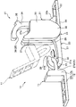
- FIG. 2 is a perspective view schematically showing a state where a first fastening member and a second fastening member of the fastener provided in the accessory of FIG. 1 are separated.
- FIG. 4 is a perspective view schematically showing a state where the first fastening member shown in FIG. 3 is temporarily held on a second fastening member. It is a side view which shows the conventional fastener.
- FIGS. 1 and 2 are a side view and a plan view schematically showing an enlarged main part of the accessory according to the present embodiment.
- FIG. 3 is a perspective view showing a state in which the first fastening member and the second fastening member of the fastener provided on the accessory are separated from each other, and
- FIG. 4 is a diagram showing the first fastening member as the second fastening member. It is a perspective view showing the state where it was temporarily held.
- the direction of the fastener along the length direction of the linear member in the jewelry will be referred to as the front-back direction.
- FIG. When viewed as such, the left-right direction on the paper surface of FIG. 1 is the front-back direction of the fastener.
- the direction perpendicular to the front-rear direction of the fastener and facing the outer peripheral side (front side) exposed to the outside of the fastener and the inner peripheral side (back side) facing human skin is defined as a vertical direction.
- the vertical direction on the paper surface of FIG. 1 is the vertical direction of the fastener.
- the direction of the outer surface exposed to the outside of the fastener is defined as upward, and the direction of the inner surface of the fastener facing human skin is defined as downward.
- a direction orthogonal to the front-rear direction and the up-down direction of the fastener is defined as a left-right direction, and in this embodiment, the front-back direction on the paper surface of FIG. 1 is the left-right direction of the fastener.
- the tennis bracelet (line bracelet) 1 of the present embodiment is a jewelry worn on a wrist.
- the tennis bracelet 1 has an elongated chain-shaped linear member 5 serving as a bracelet main body, and both ends of the linear member 5. , And the entirety of the tennis bracelet 1 can be held in a ring shape by connecting the fasteners 10.
- the linear member 5 of the tennis bracelet 1 has a plurality of top portions 6 and a connection portion 7 connecting two adjacent top portions 6, and the connection portion 7 swings with respect to the top portion 6. Mounted as possible.
- Each top section 6 has a top main body formed in a substantially quadrangular cylindrical shape or a substantially cylindrical shape, and a jewel (diamond) (not shown) fixed to an outer surface (upper surface) of the top body.
- the form and structure of the linear member 5 are not particularly limited, and can be arbitrarily changed.
- the fastener 10 of the tennis bracelet 1 is formed of metal.
- the fastener 10 is attached to a first fastening member 11 attached to one end 5 a of the linear member 5 and to the other end 5 b of the linear member 5.
- a second fastening member 21 that can be connected to and separated from the first fastening member 11.
- the first fastening member 11 of the fastener 10 includes a first connecting portion 12 to which one end 5 a of the linear member 5 of the tennis bracelet 1 is fixed and connected, and a first connecting portion 12 formed integrally with the first connecting portion 12. And one connecting portion 13.
- the first connection portion 12 includes a first connection main body portion 12a having a predetermined height dimension (a dimension in the vertical direction), and a first plate extending from the first connection main body portion 12a in one of the front and rear directions in a thin plate shape. And a connection piece 12b.
- the first connection main body 12a has a height dimension larger than that of the top body of the top section 6.
- An opening window substantially corresponding to the shape of the internal space provided in the frame body portion of the frame portion 6 is formed in the first connection piece portion 12b so as to penetrate vertically.
- one end 5a of the linear member 5 is fixed to the first connection piece 12b by welding such as brazing at a position separated from the first connection main body 12a.
- the two connection portions 6 of the linear member 5 are fixed to the first connection piece portion 12b of the first connection portion 12, so that the first fastening member 11 can be easily held by a finger. can do.
- the method for connecting the first fastening member 11 to the one end 5a of the linear member 5 is not particularly limited, and for example, the first fastening member 11 and the one end 5a of the linear member 5 are bonded.
- the first fastening member 11 and one end 5a of the linear member 5 may be connected via a round wire ring.
- first connection portion 12 of the first fastening member 11 is not large enough to fix the two top portions 6 as described above, but is large enough to fix one top portion 6 or three or more top portions 6. It may be formed by. Further, the first fastening member 11 may be formed integrally with one end of the linear member 5.
- the first connection portion 13 extends in the front-rear direction from a substantially vertical center portion of a surface of the first connection main body portion 12a opposite to the first connection piece portion 12b.
- the first connecting portion 13 is provided with an insertion hole 14 penetrating in the up-down direction.
- the first connecting portion 13 has a circular shape when viewed from above (the outer peripheral surface side) (see FIG. 2). Or an elliptical shape.
- a part of the first connecting portion 13 is held as a connecting pillar 13a by being hooked on a second connecting portion 23 of the second fastening member 21 to be described later when the first fastening member 11 and the second fastening member 21 are joined. Is done.
- the first connecting portion 13 is formed such that the cross section of the connecting column 13a has a circular shape, but in the present invention, the first connecting portion 13 is formed such that the cross section has another shape such as a substantially square shape. May be. Further, the first connecting portion 13 may be formed to have a substantially U-shape or a substantially U-shape or any other shape when viewed from above (outer peripheral surface side). good.
- the insertion hole 14 of the first connecting portion 13 is connected to a second connecting portion 23 of the second fastening member 21 (particularly, the second fastening portion 23).
- the opening 27 has a size that allows the insertion of both the tip column 27b) and the opening / closing portion 31 (particularly, the contact portion 34 of the opening / closing portion 31).
- the insertion hole portion 14 is provided with the second fastening member 21 so that the first fastening member 11 connected to the second fastening member 21 can be moved as indicated by an imaginary arrow in FIG.
- a protruding piece 35 described later is opened in a size that can be inserted together with the second connecting part 23 and the contact part 34 of the opening / closing part 31.
- the second fastening member 21 is a second connecting portion 22 to which the other end 5b of the linear member 5 of the tennis bracelet 1 is fixed and connected, and a second integrally formed from the second connecting portion 22 continuously.
- a second connecting portion 23 extending in a direction away from the second connecting portion 22 (a direction approaching the first fastening member 11) from the second main body portion 24 and having a fishhook shape; 2 has an opening / closing portion 31 rotatably arranged on the main body 24 and a locking portion 25 for maintaining the state where the opening / closing portion 31 is in contact with the second connecting portion 23.
- the second main body 24 that rotatably supports the opening / closing portion 31 is the second connecting portion 23 that is first inserted into the insertion hole 14 of the first fastening member 11.
- the second connecting portion 23 that is first inserted into the insertion hole 14 of the first fastening member 11.
- the second connecting portion 22 is formed by a rectangular frame-shaped thin plate having an opening window at substantially the center, and the other end 5 b of the linear member 5 is brazed to the second connecting portion 22. Are fixed by welding.
- the method of connecting the second fastening member 21 to the other end 5b of the linear member 5 is not particularly limited as in the case of the first fastening member 11 described above.
- the second main body portion 24 is formed integrally with the main body base portion 26, which is continuous with the second connection portion 22 and controls a rotation range of the open / close portion 31 by contacting a part of the open / close portion 31. And a support portion 28 for supporting the opening / closing portion 31.
- the main body base 26 has the same horizontal dimension (width dimension) as the second connection part 22.
- a part of the opening / closing portion 31 that rotates in the opening direction can be accommodated in the main body base portion 26 so that the rotation range of the opening / closing portion 31 is about 90 °.
- the accommodation recess 26a is provided at the center in the width direction (left-right direction) corresponding to the position of a later-described tail portion 32b of the opening / closing portion 31.
- the range of rotation of the opening / closing section 31 is defined as the range from the state where the opening / closing section 31 (particularly the tail section 23b) is locked by the locking section 25 as shown in FIG. It refers to a range in which the opening / closing unit 31 rotates until it comes into contact with the main body base 26.
- the supporting portion 28 of the second main body 24 has a smaller width in the left-right direction than the main body base 26 and is formed to project from the main body base 26 in a thin plate shape.
- the support portion 28 is formed with a bearing concave portion into which a rotating shaft portion 32 a of the opening / closing portion 31 described later is inserted, and the bearing concave portion of the supporting portion 28 and the rotating shaft portion 32 a of the opening / closing portion 31 are engaged.
- the opening / closing section 31 is rotatably supported by the second main body section 24.
- the second connecting portion 23 is formed by a hook-shaped connecting body 27 extending from the support portion 28 of the second body 24 in a direction opposite to the second connecting portion 22.
- An insertion / extraction opening 29 is formed between the distal end and the support 28 so as to be able to pass through the connection column 13 a of the first connection 13.
- connection main body 27 is formed to have a width in the left-right direction smaller than that of the second connection part 22 and the same size as the support part 28.
- the connecting body 27 includes a body column 27a extending substantially straight from the second body 24 in the front-rear direction, and a tip column 27b extending from the body column 27a via a bent portion (a waist bent portion).
- the end pillar portion 27b extends in an arc shape while bending from the bent portion toward the upper end portion of the support portion 28 in a side view of the second fastening member 21.
- the length dimension of the arc-shaped tip column portion 27b is set so that the central angle of the arc is 135 ° or more, preferably 180 ° or more.
- the tip pillar 27b moves the fastener 10 on the left and right sides in a state where the contact portion 34 of the opening / closing portion 31 is in contact with the second connecting portion 23 with a side covering portion 37 described later of the opening / closing portion 31.
- the tip column 27 b and a later-described regulating edge 37 a of the side covering portion 37 are further protected from being hidden inside the side covering portion 37.
- the length is formed so as not to reach the position of the side covering portion 37 so that a gap G is formed therebetween.
- the length of the distal end column portion 27b is set such that the minimum value of the gap G in the state of FIG. 1 is such that the connecting column 13a of the first connecting portion 13 is not inserted. That is, the gap G is formed to be smaller than the thickness of the connecting column 13a of the first connecting portion 13 (particularly, the diameter of the circular cross section of the connecting column 13a).
- the opening / closing portion 31 of the second fastening member 21 has a base end portion 32 having a rotating shaft portion 32 a pivotally supported by a bearing recess provided in the support portion 28 of the second main body portion 24, and extends from the base end portion 32.
- the locked projection 36 which is formed at the distal end and is inserted into the locking recess 27d of the second connection portion 23, and the second connection from the base end portion 32 and the closing portion 33 in the contact state of the contact portion 34.
- a thin plate-shaped side covering portion 37 extending to the left and right side positions of the body column portion 27a in the portion 23.
- a housing portion for housing the support portion 28 of the second main body portion 24, a rotating shaft portion 32a protruding left and right toward the housing portion, And a tail portion 32b that stops the rotation of the opening / closing portion 31 by contacting the bottom surface of the housing concave portion 26a provided in the main body portion 24.
- the tail portion 32b is disposed at the upper end of the base end portion 32 and has a tongue-like shape that projects obliquely upward when viewed from the side of the second fastening member 21. Since the tail portion 32b is provided in the opening / closing portion 31, for example, when the opening / closing portion 31 is rotated in the opening direction, the tail portion 32b can be easily pressed with a finger or the like. It can be done more easily.
- the closing portion 33 of the opening / closing portion 31 extends substantially linearly from the base end portion 32, and when the contact portion 34 contacts the second connecting portion 23, the insertion / extraction opening 29 of the second fastening member 21. Is closed from above with a part of the base end portion 32.
- the contact portion 34 of the present embodiment is substantially circular from the closing portion 33 so as to be able to contact at least a part of the outer peripheral surface of the tip column portion 27b in the second connecting portion 23, preferably to be in surface contact. It is formed to extend in an arc shape.
- the contact portion 34 extends from the closing portion 33 in a substantially L-shape corresponding to the shape of the second connecting portion 23. It may be.
- the protruding piece 35 protrudes obliquely upward from the portion of the curved portion of the contact portion 34 that starts to be bent outward.
- the projecting piece 35 is in a state where the first fastening member 11 and the second fastening member 21 are connected to each other, and the contact portion 34 of the second fastening member 21 is In a state in which the first fastening member 11 is in contact with the connecting portion 23, the first fastening member 11 is disposed at a position relatively close to the first connection main body 12a.
- the contact portion 34 is closer to the first fastening member 11 than the tip position of the substantially arc-shaped tip pillar 27b in the front-rear direction (the second fastening member 21). 2 remote from the connecting portion 22).
- the first fastening member 11 and the second fastening member 21 are held substantially linearly in a side view, the projecting piece 35 and the projecting piece 35 of the second fastening member 21 are connected to the first connection main body.
- the first connection main body 12a is provided separately from the first connection main body 12a so that a gap is formed between the first connection main body 12a and the first connection main body 12a.
- the projecting piece 35 is formed to be relatively short so that it can be inserted into the insertion hole 14 provided in the first fastening member 11 together with the contact part 34 of the second connecting part 23 and the opening / closing part 31.
- the protrusion length of the protrusion 35 from the contact portion 34 in the side view of the second fastening member 21 is the thickness of the contact portion 34 (inside). It is formed so as to have substantially the same size as the distance between the peripheral surface and the outer peripheral surface) and to be shorter than the thickness of the contact portion 34.
- a locked projection 36 swelling toward the inner peripheral side of the substantially arc-shaped (or substantially L-shaped) contact portion 34 is engaged with the second connecting portion 23. It is formed in a size that can be inserted into the stop recess 27d.
- the locked projection 36 provided on the opening / closing portion 31 and the locking concave portion 27d provided on the second connecting portion 23 allow the opening / closing portion when the contact portion 34 comes into contact with the second connecting portion 23.
- the locking portion 25 is configured to lock the 31 to the second connecting portion 23 and maintain the contact state.
- the form of the locking portion provided to maintain the abutting state of the abutting portion 34 is not particularly limited, and the abutting state of the abutting portion 34 can be maintained.
- the locking portion is formed in another form such as forming a concave portion or a convex portion that engages with each other on the side covering portion 37 and the body column portion 27a of the second connecting portion 23. It is also possible.
- the locked projection 36 provided on the opening / closing section 31 is perpendicular to the rotation direction of the opening / closing section 31 (in other words, orthogonal to the tip of the substantially arc-shaped abutting section 34). (In the direction in which the swelling occurs). That is, in the side view of the second fastening member 21, the swelling surface of the locked projection 36 is formed in an arc shape. Further, in the locked projection 36 of the present embodiment, when the second fastening member 21 is viewed from the side, the curved surface of the locked projection 36 protrudes from the tip of the abutting portion 34. It is provided integrally so as to form a curved surface smoothly continuing with the tip end surface. Thus, the locked projection 36 of the contact portion 34 can be smoothly inserted into and extracted from the locking recess 27d.
- the opening / closing section 31 of the present embodiment is provided with the pair of left and right side covering sections 37 as described above.
- Each side covering portion 37 is provided when the opening / closing portion 31 is closed with respect to the second connecting portion 23 (in other words, when the contact portion 34 of the opening / closing portion 31 is brought into contact with the second connecting portion 23).
- And is formed to protrude inward from the base end portion 32 and the closing portion 33 so as to cover a part of the inner space portion 30 formed in the second connecting portion 23 and the insertion / extraction opening portion 29 from the side. ing.
- the side covering part 37 is formed in such a size as to overlap at least a part of the body pillar part 27a in the second connecting part 23 in a side view of the second fastening member 21.
- the lower end edge of the side covering portion 37 and the lower end edge of the body pillar portion 27a in the second connecting portion 23 are formed to have a size that overlaps.
- the side covering portion 37 is formed between the connection portion of the closing portion 33 and the contact portion 34 and the side covering portion 37 when the second fastening member 21 is viewed from the side.
- a restricting edge portion 37a that extends obliquely from the closing portion 33 so as to form an angle smaller than 90 °.
- the side covering portion 37 is, in the state of FIG. 1, a gap formed between the distal end column portion 27 b and the regulating edge portion 37 a with respect to the distal end column portion 27 b of the second connecting portion 23.
- the minimum value of G is formed so as to be a size that does not allow the connection pillar 13a of the first connection portion 13 to be inserted as described above.
- the first fastening member 11 connected to one end 5a of the linear member 5 and the other end 5b of the linear member 5 are connected.
- first As shown in FIG.
- the insertion opening 29 of the second fastening member 21 is opened.
- the operation of rotating the opening / closing portion 31 of the second fastening member 21 can be easily performed with one hand.
- the opening / closing section 31 may be rotated with both hands.
- the first fastening member 11 is brought closer to the second fastening member 21 held on the wrist, and as shown by a virtual line in FIG. 13 a is inserted into the open insertion / extraction opening 29 of the second fastening member 21, and further inserted into the insertion hole 14 provided in the first connection portion 13 of the first fastening member 11, and the tip of the second connection portion 23 is inserted.
- the connecting column 13a of the first connecting portion 13 is moved from the insertion opening 29 to the inner space 30 surrounded by the body column 27a and the tip column 27b of the second connecting portion 23 while the column 27b is inserted.
- the connecting pillar 13a of the first connecting part 13 is brought into contact with the base end of the distal pillar 27b of the second connecting part 23.
- the first fastening member 11 can be hooked and temporarily held on the second fastening member 21.
- the operation of temporarily holding the first fastening member 11 can also be easily performed with one hand.
- the first connecting portion 13 of the first fastening member 11 has a shape that presents a circular part (or an elliptical part) in plan view as described above, Even when the member 11 is tilted obliquely with respect to the front-rear direction, for example, it is possible to easily and smoothly perform an operation of inserting the member 11 into the insertion / extraction opening 29 of the second fastening member 21 and temporarily holding the member 11 in the second connecting portion 23. It is possible.
- the short distal end column portion 27b of the second connecting portion 23 may be inserted into the insertion hole portion 14 of the first connecting portion 13; Unlike the conventional fastener 60 shown in FIG. 5, there is no need to extend the entire opening / closing portion 62d long.
- the entire distal end column portion 27b of the second connecting portion 23 is formed with substantially the same thickness. For this reason, when the tip pillar 27b of the second connection part 23 is inserted into the insertion hole 14 of the first connection part 13, the first connection part 13 of the first fastening member 11 is hardly caught by the tip pillar 27b. Become. Therefore, the first fastening member 11 can be smoothly and temporarily held by the second fastening member 21 even by one-handed operation.
- the first fastening member 11 is kept in the second fastening member. It is hard to come off from 21. Further, since the first fastening member 11 and the second fastening member 21 are pulled in a direction away from each other by the weight of the linear member 5, the temporary holding state of the first fastening member 11 is easily and stably maintained. be able to.
- the opening / closing portion 31 of the second fastening member 21 is rotated so as to approach the second connecting portion 23 (the connecting main body portion 27), and the arcuate contact of the opening / closing portion 31 is performed.
- the part 34 is brought into contact with the second connecting part 23.
- the closing portion 33 of the opening / closing portion 31 closes and closes the insertion / extraction opening 29 of the second fastening member 21 from above.
- the side covering portion 37 of the opening / closing portion 31 covers the inner space 30 of the second connecting portion 23 from the left and right sides, so that the connecting pillar 13a of the first fastening member 11 in the inner space 30.
- the movable area can be restricted (narrowed).
- the contact portion 34 of the opening / closing portion 31 in the second fastening member 21 is brought into contact with the second connection portion 23, and the contact portion 34 is connected to the first connection portion 13 of the first fastening member 11. Can be inserted from above into the insertion hole 14 formed in the hole. Further, the locked projection 36 provided at the tip of the opening / closing section 31 can be inserted and locked in the locking recess 27 d provided in the second connecting portion 23.
- the distal end column portion 27b of the second connecting portion 23 can be inserted into the insertion hole portion 14 of the first retaining member 11, so that the first retaining member 11 and the The two fastening members 21 can be more reliably connected.
- the locked projection 36 provided on the opening / closing portion 31 is locked by the second connecting portion 23, so that the contact portion 34 of the opening / closing portion 31 is kept in contact with the second connecting portion 23.
- the connection between the first fastening member 11 and the second fastening member 21 can be stably maintained.
- the opening / closing portion 31 of the second fastening member 21 is rotated to perform a connection operation between the first fastening member 11 and the second fastening member 21, thereby allowing the upper surface side (front surface side) of the fastener 10 to be connected. ) And the lower side (rear side) can be easily confirmed at the time of the connecting operation, or can be unconsciously grasped. As a result, it is difficult for the tennis bracelet 1 to be worn in a falling state, and it is possible to encourage the wearing of the ornament in the correct direction.
- the left and right side covering portions 37 of the second fastening member 21 are provided (particularly, By providing the above-mentioned oblique regulation edge portion 37a in the side covering portion 37), the movable range of the connecting column 13a of the first fastening member 11 in the inner space 30 of the second fastening member 21 is appropriately adjusted. Can be regulated. Moreover, the gap G formed between the distal end column portion 27b of the second fastening member 21 and the regulating edge portion 37a is formed in a size that does not allow the connection column 13a of the first connection portion 13 to be inserted as described above. ing.
- the connecting pillar 13 a of the first fastening member 11 can be stably fastened in the inner space 30 of the second fastening member 21.
- the first fastening member 11 and the second fastening member 21 that are connected receive a force that is pulled in a direction away from each other due to the weight of the linear member 5. Also, there is a structural effect that the state in which the connecting pillar 13a is in contact with the tip pillar 27b of the second connecting part 23 is easily maintained.
- connection pillar 13a of the first fastening member 11 pushes the opening / closing portion 31 of the second fastening member 21 in the opening direction and rotates the opening / closing portion 31 of the second fastening member 21 due to some momentum.
- the connection state of the 1st fastening member 11 and the 2nd fastening member 21 can be maintained more reliably, and it can become difficult to produce that the 1st fastening member 11 and the 2nd fastening member 21 come off without permission.
- the opening / closing section 31 receives an unintended external force and rotates the opening / closing section 31 to a position indicated by a virtual line in FIG. 1, for example, the opening / closing section 31 is pulled by the linear member 5. It does not occur that it opens further.
- the second fastening member 21 of the present embodiment is provided with a pair of left and right side covering portions 37 as described above. Therefore, the side covering portion 37 closes the insertion / extraction opening 29 of the second fastening member 21 and can prevent the connecting column 13a of the first fastening member 11 from jumping out of the inner space 30. It is possible to make it difficult.
- the first holding member 11 is held by a finger, and the connecting column 13 a of the first holding member 11 is pulled out from the inner space 30 of the second holding member 21 through the insertion / extraction opening 29, whereby the second holding member 11 is pulled out.
- the first connecting part 13 of the one retaining member 11 is detached from the second connecting part 23 of the second retaining member 21.
- the fastener 10 of the present embodiment can greatly improve the operability of the fastener 10 as compared with, for example, conventional pulling-type fasteners or insertion-type fasteners. Therefore, for example, even if a person who is not good at operating the conventional fasteners can use the accessories 10 such as the tennis bracelet 1 using the fasteners 10 of the present embodiment, the coupling operation and the separation operation of the fasteners 10 can be performed lightly. Can be used more easily and conveniently.
- the fastener 10 of the present embodiment is formed with a simple structure that is easy to mold and the like, it can be applied not only to bracelets such as the tennis bracelet 1 but also to accessories such as necklaces, pendants, and anklets. Can be applied.
- the size of the first fastening member 11 and the second fastening member 21 of the fastener 10 can be easily reduced, and the length can be easily increased or shortened along the linear member 5.
- the options of the fastener 10 that can be used for the accessory can be greatly expanded, and as a result, the design and beauty of the accessory can be more effectively expressed.
Landscapes
- Adornments (AREA)
Abstract
L'invention concerne une pièce de fixation (10) pour décoration, comprenant un premier élément de fixation (11) et une deuxième élément de fixation (21) pouvant être reliés l'un à l'autre et séparés l'un de l'autre. Le premier élément de fixation (11) comporte une première partie de raccord (12) à laquelle est raccordé un élément linéaire (5), et une première partie de liaison (13) formée solidaire de la première partie de raccord (12). Le deuxième élément de fixation (21) comprend : une deuxième partie de raccord (22) à laquelle est raccordé l'élément linéaire (5) ; une deuxième partie de corps principal (24) continue à partir de la deuxième partie de raccord (22) ; une deuxième partie de liaison (23) présentant une forme de crochet de pêche, s'étendant à partir de la deuxième partie de corps principal (24) dans une direction s'éloignant de la deuxième partie de raccord (22) et reliée à la première partie de liaison (13) ; une partie d'ouverture/fermeture (31), soutenue en rotation par la deuxième partie de corps principal (24) et pourvue d'une partie de contact sensiblement en forme de L ou sensiblement arquée (34) venant en contact avec la deuxième partie de liaison (23) ; et une partie de verrouillage (25) destinée à maintenir l'état de contact de la partie d'ouverture/fermeture (31). La présente invention permet d'effectuer facilement et sans heurts, d'une part, une opération dans laquelle la pièce de fixation (10) est reliée, et une opération dans laquelle la pièce de fixation (10) est séparée. L'invention permet également de maintenir l'état lié de façon stable.
Priority Applications (4)
| Application Number | Priority Date | Filing Date | Title |
|---|---|---|---|
| KR1020197004289A KR102113038B1 (ko) | 2018-10-03 | 2018-10-29 | 장신구용 잠금쇠 |
| EP18915785.2A EP3656244B1 (fr) | 2018-10-03 | 2018-10-29 | Élément de fixation pour décoration |
| CN201880003189.6A CN111263599A (zh) | 2018-10-03 | 2018-10-29 | 饰物用紧固件 |
| US16/603,657 US11412819B2 (en) | 2018-10-03 | 2018-10-29 | Clasp for accessory |
Applications Claiming Priority (2)
| Application Number | Priority Date | Filing Date | Title |
|---|---|---|---|
| JP2018188060 | 2018-10-03 | ||
| JP2018-188060 | 2018-10-03 |
Publications (1)
| Publication Number | Publication Date |
|---|---|
| WO2020070902A1 true WO2020070902A1 (fr) | 2020-04-09 |
Family
ID=70055312
Family Applications (1)
| Application Number | Title | Priority Date | Filing Date |
|---|---|---|---|
| PCT/JP2018/040165 Ceased WO2020070902A1 (fr) | 2018-10-03 | 2018-10-29 | Élément de fixation pour décoration |
Country Status (6)
| Country | Link |
|---|---|
| US (1) | US11412819B2 (fr) |
| EP (1) | EP3656244B1 (fr) |
| JP (1) | JP7002498B2 (fr) |
| KR (1) | KR102113038B1 (fr) |
| CN (1) | CN111263599A (fr) |
| WO (1) | WO2020070902A1 (fr) |
Families Citing this family (1)
| Publication number | Priority date | Publication date | Assignee | Title |
|---|---|---|---|---|
| CN116965622A (zh) * | 2023-08-26 | 2023-10-31 | 广州市天丰珠宝有限公司 | 一种用于首饰连接的鹰嘴扣 |
Citations (7)
| Publication number | Priority date | Publication date | Assignee | Title |
|---|---|---|---|---|
| JPS52115495U (fr) * | 1976-02-27 | 1977-09-01 | ||
| JPS5348152Y2 (fr) * | 1976-10-21 | 1978-11-17 | ||
| JPH10137016A (ja) | 1996-11-14 | 1998-05-26 | Pearl Supensaa:Kk | 装身具の留め具及びその使用方法 |
| US5832571A (en) * | 1996-04-04 | 1998-11-10 | Yama Co., Ltd. | Joint member for use in accessory |
| JP2008036244A (ja) | 2006-08-08 | 2008-02-21 | Murao:Kk | 留め金具 |
| JP2012019946A (ja) | 2010-07-14 | 2012-02-02 | Pearl Supensaa:Kk | 装身具用留め具及びこれを用いた装身具 |
| JP2018108299A (ja) * | 2017-01-05 | 2018-07-12 | 哲夫 風間 | 装身具用留め具 |
Family Cites Families (28)
| Publication number | Priority date | Publication date | Assignee | Title |
|---|---|---|---|---|
| GB191207200A (en) * | 1912-03-25 | 1913-01-30 | William Frederick Jennens | Improvements in Snaps or Fastenings for Necklets, for other Chains, and for other like uses. |
| US1637699A (en) | 1927-01-04 | 1927-08-02 | Lauterbach Samuel | Jewelry clasp |
| US1784635A (en) * | 1929-09-07 | 1930-12-09 | Jacques Kreisler & Co | Jewelry |
| FR698192A (fr) * | 1930-06-28 | 1931-01-28 | Zuccolo | Nouveau fermoir de sûreté pour bracelets |
| US2205092A (en) * | 1938-05-21 | 1940-06-18 | Gemex Co | Clasp |
| US2211018A (en) * | 1938-09-02 | 1940-08-13 | Levine Samuel | Clasp for bracelets and the like |
| US2554184A (en) * | 1946-10-19 | 1951-05-22 | Gerstenblith Simon | Connector for watch straps, bracelets, or the like |
| US2586758A (en) * | 1950-07-03 | 1952-02-19 | Zerr Karl | Jewelry chain connector |
| US2874435A (en) | 1954-08-23 | 1959-02-24 | Albert C Nielsen | Jewelry clasps |
| US3358340A (en) | 1965-10-23 | 1967-12-19 | Davis Aircraft Products Inc | Bridle buckle |
| JPS4418616Y1 (fr) * | 1966-12-29 | 1969-08-11 | ||
| US3404440A (en) * | 1967-05-02 | 1968-10-08 | Lisnow & Weiss Company | Jewelry attachment |
| JPS5647381Y2 (fr) | 1973-02-16 | 1981-11-06 | ||
| US4377924A (en) | 1976-03-01 | 1983-03-29 | Wheelabrator-Frye Inc. | Portable device for treating surfaces |
| US5168606A (en) | 1990-11-29 | 1992-12-08 | The Napier Company | Jewelry clasp with safety snap catch |
| US5279021A (en) | 1992-08-26 | 1994-01-18 | Edgin Howard L | Article retaining apparatus having pull-release/push-retain structure and method of using |
| JP2627858B2 (ja) | 1993-07-13 | 1997-07-09 | 明治合成株式会社 | ロープの結合具 |
| JP2997633B2 (ja) | 1995-05-26 | 2000-01-11 | 株式会社水本機械製作所 | 開止め機構付き環状フック |
| DE69634531T2 (de) * | 1996-04-04 | 2006-03-30 | Yama Co., Ltd. | Verbindungsteil für Schmuckstücke |
| US6202267B1 (en) * | 1998-04-17 | 2001-03-20 | D. Strickland | Ornamental jewelry catch |
| JP3299724B2 (ja) | 1998-12-01 | 2002-07-08 | 株式会社プラネット | 止め具 |
| USD489247S1 (en) | 2002-11-04 | 2004-05-04 | Coastal Pet Products, Inc. | Snap connector |
| JP3098584U (ja) | 2003-06-16 | 2004-03-04 | 株式会社桑山 | 装飾金具 |
| KR200413046Y1 (ko) * | 2006-01-13 | 2006-04-05 | 김용희 | 보조잠금장치를 가진 장식부재 |
| JP2007195606A (ja) | 2006-01-24 | 2007-08-09 | Jewel Parts Piko:Kk | 装身具用留め具及びこれを備える装身具 |
| JP3136049U (ja) | 2007-07-06 | 2007-10-11 | 株式会社ギリオン | アクセサリー用連結具 |
| US10076164B2 (en) * | 2015-05-06 | 2018-09-18 | Dream Catch Inc. | Jewelry catch |
| CN205568073U (zh) * | 2016-04-28 | 2016-09-14 | 河南梦祥纯银制品有限公司 | 一种新型饰品卡扣结构 |
-
2018
- 2018-10-29 WO PCT/JP2018/040165 patent/WO2020070902A1/fr not_active Ceased
- 2018-10-29 US US16/603,657 patent/US11412819B2/en active Active
- 2018-10-29 EP EP18915785.2A patent/EP3656244B1/fr active Active
- 2018-10-29 KR KR1020197004289A patent/KR102113038B1/ko active Active
- 2018-10-29 CN CN201880003189.6A patent/CN111263599A/zh active Pending
-
2019
- 2019-06-21 JP JP2019115775A patent/JP7002498B2/ja active Active
Patent Citations (7)
| Publication number | Priority date | Publication date | Assignee | Title |
|---|---|---|---|---|
| JPS52115495U (fr) * | 1976-02-27 | 1977-09-01 | ||
| JPS5348152Y2 (fr) * | 1976-10-21 | 1978-11-17 | ||
| US5832571A (en) * | 1996-04-04 | 1998-11-10 | Yama Co., Ltd. | Joint member for use in accessory |
| JPH10137016A (ja) | 1996-11-14 | 1998-05-26 | Pearl Supensaa:Kk | 装身具の留め具及びその使用方法 |
| JP2008036244A (ja) | 2006-08-08 | 2008-02-21 | Murao:Kk | 留め金具 |
| JP2012019946A (ja) | 2010-07-14 | 2012-02-02 | Pearl Supensaa:Kk | 装身具用留め具及びこれを用いた装身具 |
| JP2018108299A (ja) * | 2017-01-05 | 2018-07-12 | 哲夫 風間 | 装身具用留め具 |
Non-Patent Citations (1)
| Title |
|---|
| See also references of EP3656244A4 |
Also Published As
| Publication number | Publication date |
|---|---|
| EP3656244B1 (fr) | 2023-02-01 |
| US11412819B2 (en) | 2022-08-16 |
| KR102113038B1 (ko) | 2020-06-02 |
| KR20200039609A (ko) | 2020-04-16 |
| US20210219673A1 (en) | 2021-07-22 |
| EP3656244A4 (fr) | 2020-12-30 |
| CN111263599A (zh) | 2020-06-09 |
| EP3656244A1 (fr) | 2020-05-27 |
| JP2020054798A (ja) | 2020-04-09 |
| JP7002498B2 (ja) | 2022-01-20 |
Similar Documents
| Publication | Publication Date | Title |
|---|---|---|
| US11000101B2 (en) | Segmented attachment device | |
| EP0843976A1 (fr) | Fermoir pour bijoux et accessoires de mode | |
| CN211833163U (zh) | 饰品用紧固部件、饰品用紧固件以及饰品 | |
| CN102630145A (zh) | 用于腕带,特别是表带的可伸展的扣件 | |
| KR20100112867A (ko) | 원터치 로킹장치 | |
| KR101569111B1 (ko) | 착탈이 용이한 장신구용 체결장치 | |
| CN1553780A (zh) | 带有一钩扣的腕带 | |
| WO2020070902A1 (fr) | Élément de fixation pour décoration | |
| CN112399809B (zh) | 饰品用紧固部件、饰品用紧固件、饰品以及饰品用紧固部件的组装套件 | |
| KR101549948B1 (ko) | 착탈이 용이한 장신구용 체결장치 | |
| HK40023310A (en) | Fastener for ornament | |
| KR101991792B1 (ko) | 장신구의 체결장치 | |
| JP3117744U (ja) | 装身用留め金具 | |
| JP2008220648A (ja) | スライド補助具およびスライド補助具を備えた装身具 | |
| JP4647221B2 (ja) | 帯状装身具の中留 | |
| KR101569110B1 (ko) | 개폐형 장신구 체결장치 | |
| JPH09299117A (ja) | 装身具の止め金具 | |
| US20240197053A1 (en) | Ornament | |
| KR200467928Y1 (ko) | 장신구 모듈 | |
| KR20240054655A (ko) | 장신구 체결장치 | |
| JPH0730730U (ja) | 環状装身具の留め金具 | |
| JP3060035U (ja) | 装身具の止め金具 | |
| JP2018050902A (ja) | 中留及び腕時計 | |
| JP2007209529A (ja) | 磁石による連結具 | |
| JP2001000214A (ja) | クラスプ |
Legal Events
| Date | Code | Title | Description |
|---|---|---|---|
| ENP | Entry into the national phase |
Ref document number: 2018915785 Country of ref document: EP Effective date: 20191030 |
|
| NENP | Non-entry into the national phase |
Ref country code: DE |