WO2020071024A1 - 医療用雄型接続装置 - Google Patents
医療用雄型接続装置Info
- Publication number
- WO2020071024A1 WO2020071024A1 PCT/JP2019/034165 JP2019034165W WO2020071024A1 WO 2020071024 A1 WO2020071024 A1 WO 2020071024A1 JP 2019034165 W JP2019034165 W JP 2019034165W WO 2020071024 A1 WO2020071024 A1 WO 2020071024A1
- Authority
- WO
- WIPO (PCT)
- Prior art keywords
- cylinder
- male connector
- male
- screwing
- elastic piece
- Prior art date
- Legal status (The legal status is an assumption and is not a legal conclusion. Google has not performed a legal analysis and makes no representation as to the accuracy of the status listed.)
- Ceased
Links
- 0 CC*(CC1)CC1=C Chemical compound CC*(CC1)CC1=C 0.000 description 3
Images







Classifications
-
- F—MECHANICAL ENGINEERING; LIGHTING; HEATING; WEAPONS; BLASTING
- F16—ENGINEERING ELEMENTS AND UNITS; GENERAL MEASURES FOR PRODUCING AND MAINTAINING EFFECTIVE FUNCTIONING OF MACHINES OR INSTALLATIONS; THERMAL INSULATION IN GENERAL
- F16L—PIPES; JOINTS OR FITTINGS FOR PIPES; SUPPORTS FOR PIPES, CABLES OR PROTECTIVE TUBING; MEANS FOR THERMAL INSULATION IN GENERAL
- F16L19/00—Joints in which sealing surfaces are pressed together by means of a member, e.g. a swivel nut, screwed on, or into, one of the joint parts
- F16L19/005—Joints in which sealing surfaces are pressed together by means of a member, e.g. a swivel nut, screwed on, or into, one of the joint parts comprising locking means for the threaded member
-
- A—HUMAN NECESSITIES
- A61—MEDICAL OR VETERINARY SCIENCE; HYGIENE
- A61M—DEVICES FOR INTRODUCING MEDIA INTO, OR ONTO, THE BODY; DEVICES FOR TRANSDUCING BODY MEDIA OR FOR TAKING MEDIA FROM THE BODY; DEVICES FOR PRODUCING OR ENDING SLEEP OR STUPOR
- A61M39/00—Tubes, tube connectors, tube couplings, valves, access sites or the like, specially adapted for medical use
- A61M39/10—Tube connectors; Tube couplings
- A61M39/1011—Locking means for securing connection; Additional tamper safeties
-
- F—MECHANICAL ENGINEERING; LIGHTING; HEATING; WEAPONS; BLASTING
- F16—ENGINEERING ELEMENTS AND UNITS; GENERAL MEASURES FOR PRODUCING AND MAINTAINING EFFECTIVE FUNCTIONING OF MACHINES OR INSTALLATIONS; THERMAL INSULATION IN GENERAL
- F16L—PIPES; JOINTS OR FITTINGS FOR PIPES; SUPPORTS FOR PIPES, CABLES OR PROTECTIVE TUBING; MEANS FOR THERMAL INSULATION IN GENERAL
- F16L19/00—Joints in which sealing surfaces are pressed together by means of a member, e.g. a swivel nut, screwed on, or into, one of the joint parts
- F16L19/02—Pipe ends provided with collars or flanges, integral with the pipe or not, pressed together by a screwed member
- F16L19/025—Pipe ends provided with collars or flanges, integral with the pipe or not, pressed together by a screwed member the pipe ends having integral collars or flanges
-
- A—HUMAN NECESSITIES
- A61—MEDICAL OR VETERINARY SCIENCE; HYGIENE
- A61M—DEVICES FOR INTRODUCING MEDIA INTO, OR ONTO, THE BODY; DEVICES FOR TRANSDUCING BODY MEDIA OR FOR TAKING MEDIA FROM THE BODY; DEVICES FOR PRODUCING OR ENDING SLEEP OR STUPOR
- A61M39/00—Tubes, tube connectors, tube couplings, valves, access sites or the like, specially adapted for medical use
- A61M39/10—Tube connectors; Tube couplings
- A61M2039/1033—Swivel nut connectors, e.g. threaded connectors, bayonet-connectors
-
- A—HUMAN NECESSITIES
- A61—MEDICAL OR VETERINARY SCIENCE; HYGIENE
- A61M—DEVICES FOR INTRODUCING MEDIA INTO, OR ONTO, THE BODY; DEVICES FOR TRANSDUCING BODY MEDIA OR FOR TAKING MEDIA FROM THE BODY; DEVICES FOR PRODUCING OR ENDING SLEEP OR STUPOR
- A61M39/00—Tubes, tube connectors, tube couplings, valves, access sites or the like, specially adapted for medical use
- A61M39/10—Tube connectors; Tube couplings
- A61M2039/1083—Tube connectors; Tube couplings having a plurality of female connectors, e.g. Luer connectors
-
- A—HUMAN NECESSITIES
- A61—MEDICAL OR VETERINARY SCIENCE; HYGIENE
- A61M—DEVICES FOR INTRODUCING MEDIA INTO, OR ONTO, THE BODY; DEVICES FOR TRANSDUCING BODY MEDIA OR FOR TAKING MEDIA FROM THE BODY; DEVICES FOR PRODUCING OR ENDING SLEEP OR STUPOR
- A61M39/00—Tubes, tube connectors, tube couplings, valves, access sites or the like, specially adapted for medical use
- A61M39/10—Tube connectors; Tube couplings
- A61M2039/1088—Tube connectors; Tube couplings having a plurality of male connectors, e.g. Luer connectors
-
- A—HUMAN NECESSITIES
- A61—MEDICAL OR VETERINARY SCIENCE; HYGIENE
- A61M—DEVICES FOR INTRODUCING MEDIA INTO, OR ONTO, THE BODY; DEVICES FOR TRANSDUCING BODY MEDIA OR FOR TAKING MEDIA FROM THE BODY; DEVICES FOR PRODUCING OR ENDING SLEEP OR STUPOR
- A61M2205/00—General characteristics of the apparatus
- A61M2205/02—General characteristics of the apparatus characterised by a particular materials
- A61M2205/0216—Materials providing elastic properties, e.g. for facilitating deformation and avoid breaking
Definitions
- the present invention relates to a male connection device used in conjunction with a female connector to connect medical components such as tubes.
- a connection structure of the type disclosed in Patent Document 1 includes a male connection device 1 and a female connector 2 as shown in FIGS.
- the male connection device 1 has a male connector 10 and a screwing cylinder 20 rotatably attached to the male connector 10.
- the screwing tube 20 has a screwing portion 21 located radially outside the male luer portion 11 of the male connector 10, and a female screw 21 a is formed on the inner periphery of the screwing portion 21.
- the female connector 2 has a female luer portion 2a, and an engagement protrusion 2c screwed with the female screw 21a is formed on the outer periphery of the distal end of the female luer portion 2a.
- the male luer portion 11 and the female luer portion 2a are displaced by the fluid pressure in a direction in which the male luer portion 11 and the female luer portion 2a are separated from each other. And the liquid may leak from between the male luer portion 11 and the female luer portion 2a.
- FIGS. 1 to 6 of Patent Document 2 disclose a medical connection structure with a torque limit mechanism developed by the present inventors. Also in this medical connection structure, similarly to the connection structure of FIGS. 13 and 14 described above, the rotation of the screwing cylinder in the loosening direction cannot be prohibited.
- FIGS. 73 to 75 of Patent Document 3 disclose a locking mechanism disposed between a male connector and a screw-in tube. This loosening prevention mechanism engages a large number of first engagement projections formed at equal intervals on the inner periphery of the screwing cylinder with second engagement projections formed on the outer periphery of the male connector. This prohibits the loosening of the screw cylinder.
- the present invention has been made to solve the above problems, and includes a cylindrical male connector, and a screwing cylinder rotatably connected to the male connector, wherein the male connector has a distal end.
- the male connector has a distal end.
- the mounting portion of the screwing cylinder is rotatably mounted on the outer periphery of the support portion of the male connector, and the screwing portion has a female screw on the inner circumference and is disposed radially outside of the male luer portion.
- the male connector further includes a loosening prevention mechanism disposed between the male connector and the screwing cylinder.
- the loosening prevention mechanism forbids rotation of the screwing cylinder in the loosening direction with respect to the male connector.
- a ratchet tooth formed on the entire inner circumference of the screwing cylinder, and at least one elastic member formed on the outer circumference of the male connector and extending in the circumferential direction and having a free end separated from the outer circumference of the male connector;
- Piece having an engaging claw formed at a free end of the elastic piece and protruding radially outward
- the screwing cylinder in a state where the male luer portion is joined to the female luer portion of the female connector, the screwing cylinder is loosened relative to the male connector due to the engagement between the ratchet teeth of the loosening prevention mechanism and the engagement claws. Can be prohibited, and a good joining state between the lure portions can be maintained.
- the screwing cylinder is tightened, the elastic piece is elastically deformed inward in the radial direction, and the engaging claw gets over the ratchet teeth of the screwing cylinder, so that no large resistance is generated and the joining operation is performed smoothly. be able to.
- the elastic piece extends in the circumferential direction, when a rotational torque in the tightening direction or the loosening direction is applied to the screwing cylinder, no twisting force is applied to the elastic piece, and the strength of the elastic piece is maintained. it can.
- the elastic piece extends in a tightening direction of the screw tube.
- the screwing cylinder when a rotational torque in the tightening direction is applied to the screwing cylinder, the screwing cylinder is easily elastically deformed, and the joining operation can be further facilitated. Further, when the rotational torque in the loosening direction is applied to the threaded cylinder, the engagement of the engaging claw with the ratchet teeth is deepened, so that the threaded cylinder can be more securely prevented from being loosened from the male connector.
- a support projection is formed on an outer periphery of the male connector, which protrudes radially outward, and the elastic piece extends in a circumferential direction from a tip end of the support projection.
- a chamfered flat surface is formed on the outer periphery of the male connector, and the support protrusion is connected to a circumferential end of the flat surface, and the elastic piece extends along the flat surface. It extends and is spaced from the flat surface.
- the elastic piece can be elastically deformed in the radially inward direction without largely projecting the elastic piece from the outer periphery of the male connector in the radially outward direction.
- a reinforcement protrusion connected to the support projection is formed on the outer periphery of the male connector on the side opposite to the elastic piece. According to the above configuration, even when a strong rotational torque acts on the screwing cylinder and a strong force is applied to the elastic piece toward the support protrusion, the elastic protrusion can be received by the reinforcing protrusion. Strength can be reliably maintained.
- the torque limit mechanism is Transmitting the rotational torque in the tightening direction of the operating cylinder to the screwing cylinder, and when the rotating torque exceeds a set torque, causes the operating cylinder to idle relative to the screwing cylinder, and the torque limit mechanism includes: Engaging teeth formed on the inner circumference of the operation cylinder over the entire circumference; at least one elastically deformable portion formed on the screwing cylinder; and a radially outwardly protruding engagement member formed on the elastically deformable portion.
- a second engaging claw that meshes with the denture wherein an elastic coefficient of the elastic deformation portion is larger than the elastic piece of the loosening prevention mechanism.
- the elastic deformation portion is formed at an end of the mounting portion of the screwing cylinder, and the ratchet tooth of the loosening prevention mechanism is provided on an inner periphery of the mounting portion so as to be axially adjacent to the elastic deformation portion. Are formed.
- the resistance of a loosening prevention mechanism at the time of rotation of a screwing cylinder in a tightening direction is small, and even if rotational torque of a tightening direction or a loosening direction is given to a screwing cylinder, the elasticity of a loosening prevention mechanism is sufficient.
- the pieces can maintain strength.
- FIG. 1 is a perspective view showing a medical male connection device and a female connector according to a first embodiment of the present invention. It is a longitudinal section of the above-mentioned male type connection device. It is a longitudinal section showing the above-mentioned male type connection device in the state where it was connected to the above-mentioned female type connector.
- FIG. 3 is an exploded perspective view of the male connection device. It is the perspective view which looked at the said male-type connection apparatus from the direction different from FIG.
- FIG. 5 is an exploded perspective view of the male connection device as viewed from the same direction as FIG. 4. It is a top view which shows the male connector of the said male connection device.
- FIG. 6B is a sectional view taken along the line BB in FIG. 6A.
- FIG. 6B is a sectional view taken along the line CC in FIG. 6B. It is a top view which shows the screwing cylinder of the said male connection device. It is BB arrow sectional drawing in FIG. 7A.
- FIG. 7B is a diagram viewed from a direction C in FIG. 7B. It is a longitudinal section of an operation cylinder of the above-mentioned male type connection device. It is the figure seen from the B direction in FIG. 8A.
- FIG. 2B is a sectional view taken along the line IX-IX in FIG. 2B.
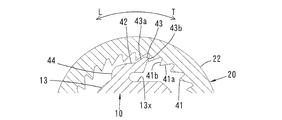
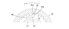
- FIG. 10 is an enlarged cross-sectional view illustrating a main part of the loosening prevention mechanism in FIG. 9 in a state in which no rotational torque is applied to the screwing cylinder.
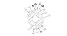
- FIG. 6C is a diagram corresponding to FIG. 6C showing a second embodiment of the present invention. It is a perspective view showing the male connector of the 2nd embodiment. It is a longitudinal section showing the conventional medical connection structure provided with the male type connecting device and the female type connector, and shows the state where joining of the male type luer part and the female type luer part was completed by fastening of the screwing cylinder. It is a longitudinal cross-sectional view which shows the said conventional medical connection structure, and shows the state in which the screwing cylinder was loosened with respect to the male connector.
- the male connection device 1 cooperates with a female connector 2 to connect tubes 5 and 5 ′ (first and second medical components) through which a liquid such as a drug solution or blood flows. Things.
- Each component of the male connection device 1 and the female connector 2 are formed of resin.
- the female connector 2 having a simple configuration will be described with reference to FIGS. 1 and 2B.
- the female connector 2 has an elongated cylindrical shape, has a female luer portion 2a at one axial end (distal end), and has a connecting portion 2b at the other end (base end).
- the inner surface of the female luer portion 2a has a gentle taper whose diameter increases toward the tip.
- a pair of engaging projections 2c serving as male threads are formed on the outer periphery of the distal end portion of the female luer portion 2a at 180 degrees apart in the circumferential direction.
- the end of the tube 5 ' is inserted and fixed to the connecting portion 2b.
- the male connection device 1 includes a male connector 10 and a screwing cylinder 20 rotatably mounted on the outer periphery of the male connector 10 so as not to move in the axial direction. And an operation tube 30 rotatably mounted on the outer periphery of the screwing tube 20 so as not to move in the axial direction.
- the male connector 10 has an elongated tubular shape, has a male luer portion 11 at one axial end (a distal end), and has a male luer 11 at the other end (a proximal end). It has a connecting portion 12 and a supporting portion 13 at an intermediate portion.
- the outer surface of the male luer part 11 has a gentle taper whose diameter decreases toward the tip.
- the taper angle of the outer surface of the male luer portion 11 is substantially equal to the taper angle of the inner surface of the female luer portion 2a.
- the end of the tube 5 is inserted and fixed to the connecting portion 12.
- the screwing cylinder 20 has a screwing portion 21 at one axial end (distal end) and a mounting portion 22 at the other end (base end). ing.
- a female screw 21 a is formed on the inner periphery of the screw portion 21.
- the mounting portion 22 is mounted on the support portion 13 of the male connector 10 so as to be rotatable and immovable in the axial direction.
- the screwing portion 21 of the screwing tube 20 is arranged radially outside the male luer portion 11.
- An annular insertion space 25 is formed between the screw portion 21 and the male luer portion 11.
- An annular gap 26 is formed between the small diameter portion of the support portion 13 of the male connector 10 and the mounting portion 22 of the screwing tube 20.
- the male connection device 1 includes a loosening prevention mechanism 40 arranged in the annular space 26.
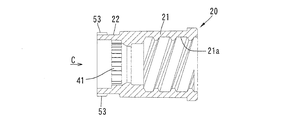
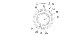
- the loosening prevention mechanism 40 includes a ratchet tooth 41 formed over the entire inner circumference of the mounting portion 22 of the screwing cylinder 20 as shown in FIGS. 5, 7B, and 7C, and FIGS. 3, 6A to 6C.
- a pair of elastic pieces 42 formed on the small diameter portion of the support portion 13 of the male connector 10 as shown in FIG.
- the ratchet teeth 41 are formed at a portion of the mounting portion 22 of the screwing cylinder 20 at a predetermined distance from the base end. As shown in FIG. 10A, the ratchet teeth 41 form an inclined surface 41a on a tightening direction T side described later, and form a steep surface 41b on a loosening direction L side.
- a pair of chamfered flat surfaces 13x is formed at the small diameter portion of the cylindrical portion of the support portion 13 of the male connector 10.
- the pair of flat surfaces 13x face each other in the radial direction and are parallel to each other.
- a support protrusion 44 projects radially and outwardly from a circumferential end (an end on the loosening direction L side) of the flat surface 13x of the support portion 13.
- the piece 42 extends substantially in parallel with the flat surface 13x in the fastening direction T (circumferential direction).
- the support projection 44 and the elastic piece 42 are substantially L-shaped.
- the elastic piece 42 is separated from the flat surface 13x, and an engaging claw 43 projecting outward in the radial direction is formed at the tip (free end) of the elastic piece 42.
- the pair of engaging claws 43 are engaged with the ratchet teeth 41.
- the engaging claw 43 has an inclined surface 43 a on the loosening direction L side and a steep surface 43 b on the tightening direction T side, and the inclined surface 41 a of the ratchet teeth 41 and the inclined surface of the engaging claw 43.
- Reference numeral 43a faces in the circumferential direction
- steep surfaces 41b and 43b face in the circumferential direction.
- the male connection device 1 of the present embodiment also includes a torque limit mechanism 50 disposed between the screwing cylinder 20 and the operation cylinder 30.
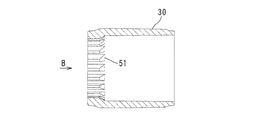
- the torque limit mechanism 50 is engaged with an engaging tooth 51 formed over the entire inner circumference of the base end portion of the operating cylinder 30 as shown in FIGS. 5 and 8, and is screwed as shown in FIGS.
- An elastic deformation portion 52 formed at the base end of the cylinder 20.
- the engaging teeth 51 form an inclined surface 51 a on the tightening direction T side and a steep surface 51 b on the loosening direction L side, similarly to the ratchet teeth 41 of the loosening prevention mechanism 40.
- a pair of slits 54 are formed at an end of the mounting portion 22 of the screwing cylinder 20 at 180 degrees in the circumferential direction.
- the slit 54 extends in the axial direction from the end of the mounting section 22.
- a portion adjacent to the slit 54 is provided as an elastic deformation portion 52.
- the elastic deformation portion 52 is adjacent to the ratchet teeth 41 of the loosening prevention mechanism 40 in the axial direction.
- the elastic coefficient of the elastic deformation portion 52 is much larger than the elastic piece 42 of the loosening prevention mechanism 40.
- An engagement claw 53 (second engagement claw) is formed on the outer surface of each elastic deformation portion 52 at a position adjacent to the slit 54, and the engagement claw 53 is spaced from the engagement claw 53 by one pitch of the engagement teeth 51.
- Another engaging claw 53 (second engaging claw) that is only apart in the circumferential direction is formed. As shown in FIG. 9, these engaging claws 53 project radially outwardly and are engaged with the engaging teeth 51.
- the engaging claw 53 forms an inclined surface 53a on the loosening direction L side and forms a steep surface 53b on the tightening direction T side.
- the inclined surface 51a and the inclined surface 53a of the engaging claw 53 face in the circumferential direction, and the steep surfaces 51b and 53b face in the circumferential direction.
- the female connector 2 is brought close to the male connection device 1 having the above configuration, and the male luer portion 11 is inserted into the female luer portion 2a. The insertion is proceeded without resistance until the engagement protrusion 2c of the female connector 2 hits the female screw 21a of the screwing cylinder 20 of the male connection device 1.
- the screwing tube 20 does not turn in the loosening direction with respect to the male connector 10, so as shown in FIG.
- the state where the surface 21x on the inner side of the thread of the female screw 21a of 20 is in contact with the engagement protrusion 2c of the female connector 2 is maintained.
- the female luer portion 2a and the male luer portion 11 are not displaced in a direction in which they are separated from each other, so that a sufficient sealing performance can be maintained, and the leakage of the fluid can be inhibited.
- the operation cylinder 30 is turned in the loosening direction L. Then, in the torque limit mechanism 50, the steep surface 51 b of the engagement tooth 51 of the operation cylinder 30 hits the steep surface 53 b of the engagement claw 53 of the screw cylinder 20, and the screw cylinder 20 moves together with the operation cylinder 30 in the loosening direction. spin. At the same time, in the loosening prevention mechanism 40, the steep face 41 b of the ratchet tooth 41 of the screwing cylinder 20 hits the steep face 43 b of the engaging piece 43 of the male connector 10, and the male connector 10 also moves together with the screwing pipe 20. spin. As a result, the joined state of the male luer part 11 and the female luer part 2a is released.
- the elastic piece 42 of the loosening prevention mechanism 40 extends in the circumferential direction, there are the following advantages. As described above, when the screwing cylinder 20 receives the rotational torque in the loosening direction L, the elastic piece 42 is subjected to a circumferential force on the elastic piece 42 due to the engagement between the steep surface 41b of the ratchet tooth 41 and the steep surface 43b of the engaging claw 43. Works. Further, even when the screwing cylinder 20 receives the rotation torque in the tightening direction T, the circumferential force acts on the elastic piece 42 due to the friction between the inclined surface 41 a of the ratchet teeth 41 and the inclined surface 43 a of the engaging claw 43. I do. However, since the elastic piece 42 extends in the circumferential direction, the elastic piece 42 is not twisted by the circumferential force as described above, and the strength of the elastic piece 42 can be maintained.
- the elastic piece 42 extends in the tightening direction T in the circumferential direction, when the screwing cylinder 20 is given a rotational torque in the tightening direction T, it is easily elastically deformed, and the joining operation is further facilitated. be able to. Further, when a rotational torque in the loosening direction L is applied to the screwing cylinder 20, a force is applied to the elastic piece 42 via the engaging claw 43 in a direction to cause the elastic piece 43. Since the engagement with the ratchet teeth 41 is deepened, the loosening of the screwing tube 20 with respect to the male connector 10 can be more reliably prevented.
- a support protrusion 44 is formed that protrudes radially and outwardly from the outer periphery of the support portion 13 of the male connector 10, and the elastic piece 42 extends in the circumferential direction from the tip of the support protrusion 44. Since the elastic piece 42 is elastically deformed radially inward mainly at the intersection of the support projection 44 and the elastic piece 42 as a fulcrum, it is possible to further reduce the resistance when turning the screwing cylinder 20 in the tightening direction T. it can.
- the elastic piece 42 since the elastic piece 42 is arranged along the flat surface 13x of the support portion 13 of the male connector 10, the elastic piece 42 does not protrude greatly from the support portion 13 in the radially outward direction. The elastic deformation in the inward direction is possible.
- a second embodiment of the present invention will be described with reference to FIGS.
- This embodiment is the same as the first embodiment except for the main part of the male connector 10.
- a reinforcing protrusion 45 is formed on the outer periphery of the small diameter portion of the support portion 13.
- the reinforcement protrusion 45 is connected to the support protrusion 44 on the opposite side of the elastic piece 42.
- the elastic protrusion 42 can receive the elastic protrusion 42 with the reinforcing protrusion 45.
- the strength of the support 42 and the support protrusion 44 can be reliably maintained.
- the present invention is not limited to the above embodiment, and various modes are possible.
- the elastic piece of the loosening prevention mechanism may extend in the circumferential direction in the loosening direction.
- the operation cylinder and the torque limit mechanism may be omitted.
- the mounting portion and the connecting portion of the male connector may be separated and rotatable with each other.
- the present invention may be applied to the connection between a three-way stopcock and a tube, or to the connection of all medical components.
- the present invention can be applied to a male connection device used for a medical connection structure.
Landscapes
- Health & Medical Sciences (AREA)
- Engineering & Computer Science (AREA)
- Heart & Thoracic Surgery (AREA)
- General Engineering & Computer Science (AREA)
- Hematology (AREA)
- Pulmonology (AREA)
- Anesthesiology (AREA)
- Biomedical Technology (AREA)
- Life Sciences & Earth Sciences (AREA)
- Animal Behavior & Ethology (AREA)
- General Health & Medical Sciences (AREA)
- Public Health (AREA)
- Veterinary Medicine (AREA)
- Mechanical Engineering (AREA)
- Infusion, Injection, And Reservoir Apparatuses (AREA)
- Joints With Pressure Members (AREA)
Abstract
Description
雄型接続装置1は、雄型コネクタ10と、この雄型コネクタ10に回転可能に取り付けられた螺合筒20とを有している。螺合筒20は、雄型コネクタ10の雄型ルアー部11の径方向外側に位置する螺合部21を有し、この螺合部21の内周には雌ねじ21aが形成されている。
雌型コネクタ2は雌型ルアー部2aを有しており、この雌型ルアー部2aの先端部外周には上記雌ねじ21aに螺合する係合突起2cが形成されている。
さらに、上記雄型コネクタと上記螺合筒との間に配置された緩み防止機構を備え、上記緩み防止機構は、上記雄型コネクタに対する上記螺合筒の緩み方向の回動を禁じるものであり、上記螺合筒の内周に全周にわたって形成されたラチェット歯と、上記雄型コネクタの外周に形成されて周方向に延びその自由端が上記雄型コネクタの外周から離間した少なくとも1つの弾性片と、上記弾性片の自由端に形成されて径方向外方向に突出する係合爪とを有し、
上記螺合筒が締め付け方向の回動トルクを受けた時には、上記弾性片の径方向内方向の弾性変形を伴って上記係合爪が上記ラチェット歯を乗り越えることにより、上記螺合筒の上記雄型コネクタに対する回動を許容し、上記螺合筒が緩み方向の回動トルクを受けた時には、上記係合爪が上記ラチェット歯を係止することにより、上記螺合筒の上記雄型コネクタに対する回動を禁じることを特徴とする。
上記構成によれば、螺合筒が締め付け方向の回転トルクを付与された時に、弾性変形し易く、より一層接合作業を楽にすることができる。また、螺合筒が緩み方向の回転トルクを付与された時に、係合爪のラチェット歯への噛み合いが深まるため、螺合筒の雄型コネクタに対する緩みをより一層確実に防止することができる。
上記構成によれば、螺合筒を締め付け方向へ回す際に、弾性片は弾性変形し易く、より一層接合作業を楽にすることができる。
上記構成によれば、弾性片を雄型コネクタの外周から径方向外方向に大きく突出させずに、径方向内方向への弾性変形が可能である。
上記構成によれば、螺合筒に強い回転トルクが作用して、弾性片に支持凸部に向かう強い力が加わった時でも、補強隆起部で受け止めることができ、弾性片および支持凸部の強度を確実に維持することができる。
上記構成によれば、螺合筒に過剰なトルクが付与されず、雄型ルアー部と雌型ルアー部が離脱不能な程に噛み付く等の不都合を回避できる。
図1に示すように雄型接続装置1は、雌型コネクタ2と協働して、薬液や血液等の液体を流すチューブ5、5’(第1、第2の医療構成要素)を接続するものである。雄型接続装置1の各構成部材および雌型コネクタ2は樹脂により形成されている。
上記支持部13の平坦面13xの周方向端部(緩み方向L側の端部)から、径方向、外方向に支持凸部44が突出しており、この支持凸部44の先端から、上記弾性片42が平坦面13xと略平行をなして締め付け方向T(周方向)に延びている。これら支持凸部44と弾性片42は略L字形をなしている。弾性片42は平坦面13xから離間しており、弾性片42の先端(自由端)には、径方向外方向に突出する係合爪43が形成されている。
図8B、図9に示すように、係合歯51は緩み防止機構40のラチェット歯41と同様に、締め付け方向T側が傾斜面51aをなし、緩み方向L側が急峻面51bをなしている。
上述したように螺合筒20が緩み方向Lの回転トルクを受けた時、ラチェット歯41の急峻面41bと係合爪43の急峻面43bの係止により、弾性片42には周方向の力が作用する。また、螺合筒20が締め付け方向Tの回転トルクを受けた時にも、ラチェット歯41の傾斜面41aと係合爪43の傾斜面43aの摩擦によって、弾性片42には周方向の力が作用する。しかし、弾性片42は周方向に延びているため、上記のような周方向の力によって捩れが生じず、弾性片42の強度を維持することができる。
緩み防止機構の弾性片は周方向において緩み方向に延びていてもよい。
操作筒とトルクリミット機構は省いてもよい。
雄型コネクタの装着部と連結部が分離して互いに回動可能であってもよい。
本発明を三方活栓とチューブの接続に適用してもよいし、あらゆる医療用構成要素の接続に適用することができる。
Claims (7)
- 筒形状の雄型コネクタ(10)と、上記雄型コネクタに回転可能に連結された螺合筒(20)と、を備え、
上記雄型コネクタが、先端から基端に向かって順に配置された雄型ルアー部(11)と支持部(13)とを有し、
上記螺合筒(20)が、先端から基端に向かって順に配置された螺合部(21)と装着部(22)とを有し、
上記螺合筒の上記装着部(22)が上記雄型コネクタの上記支持部(13)外周に回転可能に装着され、上記螺合部が内周に雌ねじ(21a)を有するとともに上記雄型ルアー部(11)の径方向外側に配置されている医療用雄型接続装置において、
さらに、上記雄型コネクタ(10)と上記螺合筒(20)との間に配置された緩み防止機構(40)を備え、上記緩み防止機構は、上記雄型コネクタに対する上記螺合筒の緩み方向の回動を禁じるものであり、上記螺合筒の内周に全周にわたって形成されたラチェット歯(41)と、上記雄型コネクタの外周に形成されて周方向に延びその自由端が上記雄型コネクタ(10)の外周から離間した少なくとも1つの弾性片(42)と、上記弾性片の自由端に形成されて径方向外方向に突出する係合爪(43)とを有し、
上記螺合筒(20)が締め付け方向の回動トルクを受けた時には、上記弾性片(42)の径方向内方向の弾性変形を伴って上記係合爪(43)が上記ラチェット歯(41)を乗り越えることにより、上記螺合筒の上記雄型コネクタ(10)に対する回動を許容し、
上記螺合筒(20)が緩み方向の回動トルクを受けた時には、上記係合爪(43)が上記ラチェット歯(41)を係止することにより、上記螺合筒の上記雄型コネクタ(10)に対する回動を禁じることを特徴とする医療用雄型接続装置。 - 上記弾性片(42)が上記螺合筒(20)の締め付け方向に延びていることを特徴とする請求項1に記載の医療用雄型接続装置。
- 上記雄型コネクタ(10)の外周には、径方向外方向に突出する支持凸部(44)が形成され、この支持凸部の先端から上記弾性片(42)が周方向に延びていることを特徴とする請求項1または2に記載の医療用雄型接続装置。
- 上記雄型コネクタ(10)の外周には、面取された平坦面(13x)が形成され、
上記平坦面の周方向端部に上記支持凸部(44)が連なっており、上記弾性片(42)が上記平坦面に沿って延びるとともに上記平坦面から離間していることを特徴とする請求項3に記載の医療用雄型接続装置。 - 上記雄型コネクタ(10)の外周には上記弾性片(42)の反対側において上記支持凸部(44)に連なる補強隆起部(45)が形成されていることを特徴とする請求項3に記載の医療用雄型接続装置。
- さらに、上記螺合筒の外周に回動可能に装着された操作筒(30)と、上記螺合筒(20)と上記操作筒との間に配置されたトルクリミット機構(50)とを備え、
上記トルクリミット機構は、上記操作筒の締め付け方向の回転トルクを上記螺合筒に伝達し、上記回転トルクが設定トルクを越えた時に、上記操作筒を上記螺合筒に対して空回りさせ、
上記トルクリミット機構は、上記操作筒の内周に全周にわたって形成された係合歯(51)と、上記螺合筒に形成された少なくとも1つの弾性変形部(52)と、上記弾性変形部に形成されて径方向外方向に突出し上記係合歯に噛み合う第2の係合爪(53)とを有し、上記弾性変形部の弾性係数が上記緩み防止機構の上記弾性片より大きいことを特徴とする請求項1に記載の医療用雄型接続構造。 - 上記螺合筒(20)の上記装着部(22)の端部に上記弾性変形部(52)が形成され、上記装着部の内周には上記弾性変形部に軸方向に隣接して上記緩み防止機構(40)の上記ラチェット歯(41)が形成されていることを特徴とする請求項6に記載の医療用雄型接続構造。
Priority Applications (4)
| Application Number | Priority Date | Filing Date | Title |
|---|---|---|---|
| CN201980039149.1A CN112261966B (zh) | 2018-10-04 | 2019-08-30 | 医疗用公连接装置 |
| US17/054,377 US12083308B2 (en) | 2018-10-04 | 2019-08-30 | Male connecting device for medical use |
| JP2020550205A JP7020724B2 (ja) | 2018-10-04 | 2019-08-30 | 医療用雄型接続装置 |
| EP19868995.2A EP3777958B1 (en) | 2018-10-04 | 2019-08-30 | Male connecting device for medical use |
Applications Claiming Priority (2)
| Application Number | Priority Date | Filing Date | Title |
|---|---|---|---|
| JP2018-188958 | 2018-10-04 | ||
| JP2018188958 | 2018-10-04 |
Publications (1)
| Publication Number | Publication Date |
|---|---|
| WO2020071024A1 true WO2020071024A1 (ja) | 2020-04-09 |
Family
ID=70054737
Family Applications (2)
| Application Number | Title | Priority Date | Filing Date |
|---|---|---|---|
| PCT/JP2019/032019 Ceased WO2020070983A1 (ja) | 2018-10-04 | 2019-08-15 | 医療用接続構造 |
| PCT/JP2019/034165 Ceased WO2020071024A1 (ja) | 2018-10-04 | 2019-08-30 | 医療用雄型接続装置 |
Family Applications Before (1)
| Application Number | Title | Priority Date | Filing Date |
|---|---|---|---|
| PCT/JP2019/032019 Ceased WO2020070983A1 (ja) | 2018-10-04 | 2019-08-15 | 医療用接続構造 |
Country Status (5)
| Country | Link |
|---|---|
| US (2) | US11872366B2 (ja) |
| EP (2) | EP3777957B8 (ja) |
| JP (2) | JP6918324B2 (ja) |
| CN (2) | CN112261967B (ja) |
| WO (2) | WO2020070983A1 (ja) |
Families Citing this family (12)
| Publication number | Priority date | Publication date | Assignee | Title |
|---|---|---|---|---|
| JP7385917B2 (ja) * | 2019-12-26 | 2023-11-24 | 株式会社タカギ | ラチェット機構を備えた継手 |
| US11554258B2 (en) * | 2020-02-26 | 2023-01-17 | Becton, Dickinson And Company | Syringe with snap-in enteral connection feature |
| JP7573162B2 (ja) * | 2021-02-01 | 2024-10-25 | 株式会社ジェイ・エム・エス | 医療用コネクタ |
| IL305598B2 (en) | 2021-03-03 | 2026-02-01 | Equashield Medical Ltd | Luer-proof connector and valve assembly for adapter |
| CN114225211A (zh) * | 2021-11-30 | 2022-03-25 | 宁波天益医疗器械股份有限公司 | 一种鲁尔接头 |
| CN115059811B (zh) * | 2022-06-08 | 2023-09-15 | 东台市创成建筑科技有限公司 | 一种管道防爆裂防拧死连接管件 |
| TWI819713B (zh) * | 2022-07-19 | 2023-10-21 | 緯創資通股份有限公司 | 快速接頭組及其插頭及插座 |
| TWI865046B (zh) * | 2022-10-11 | 2024-12-01 | 光紅建聖股份有限公司 | 電連接器組件 |
| US20240139490A1 (en) * | 2022-10-31 | 2024-05-02 | Becton, Dickinson And Company | Luer connector for vascular access devices |
| USD1055279S1 (en) | 2023-04-17 | 2024-12-24 | iMed Technology, Inc. | Feeding tube set inlet component |
| USD1069109S1 (en) * | 2023-04-17 | 2025-04-01 | iMed Technology, Inc. | Feeding tube set inlet component |
| US12611638B2 (en) | 2023-10-24 | 2026-04-28 | Sharkninja Operating Llc | Ratchet system for a gas canister in a beverage system |
Citations (8)
| Publication number | Priority date | Publication date | Assignee | Title |
|---|---|---|---|---|
| JPS4823058Y1 (ja) * | 1968-11-25 | 1973-07-05 | ||
| JPS566499U (ja) * | 1979-06-28 | 1981-01-20 | ||
| JPS5987840U (ja) | 1982-12-07 | 1984-06-14 | 住友ベークライト株式会社 | ルア−ロツクコネクタ− |
| JPH09182878A (ja) * | 1995-12-28 | 1997-07-15 | Seikouken Kk | 手巻き式ゼンマイ駆動ユニット |
| US6152913A (en) * | 1995-04-27 | 2000-11-28 | The Kippgroup | Medical luer connection having protective cap with crush rib |
| US20080172039A1 (en) * | 2006-10-02 | 2008-07-17 | B. Braun Medical Inc. | Ratcheting luer lock connector |
| JP2010527276A (ja) | 2007-05-16 | 2010-08-12 | アイシーユー・メディカル・インコーポレーテッド | 閉鎖可能な雄ルアーを備える医療用コネクタ |
| WO2016157974A1 (ja) | 2015-04-02 | 2016-10-06 | 光陽産業株式会社 | 医療用接続構造 |
Family Cites Families (11)
| Publication number | Priority date | Publication date | Assignee | Title |
|---|---|---|---|---|
| JPS566499A (en) | 1979-06-26 | 1981-01-23 | Sanyo Electric Co | Hybrid integrated circuit unit |
| JPS5987840A (ja) | 1982-11-10 | 1984-05-21 | Toray Silicone Co Ltd | 半導体装置 |
| DE20109061U1 (de) * | 2001-05-31 | 2001-08-09 | B. Braun Melsungen Ag, 34212 Melsungen | Patienten-Sicherheitskonnektor |
| US7984933B2 (en) * | 2008-02-28 | 2011-07-26 | Diba Industries, Inc. | Multi-use torque fitting and compressible ferrule |
| JP5875974B2 (ja) * | 2010-03-30 | 2016-03-02 | テルモ株式会社 | コネクタおよびコネクタ組立体 |
| US8888143B2 (en) * | 2011-09-23 | 2014-11-18 | Diba Industries, Inc. | Torque limiting fastening assemblies and fluid coupling assemblies including the same |
| EP2815786B1 (en) * | 2012-02-13 | 2016-12-28 | Nipro Corporation | Needle-less connector |
| JP6001903B2 (ja) * | 2012-03-30 | 2016-10-05 | 大研医器株式会社 | 接続部材 |
| US9279526B2 (en) * | 2013-03-14 | 2016-03-08 | Mcalister Technologies, Llc | Apparatuses and methods for providing finger-tightened and ratchet-secured connections between conduits |
| WO2015087880A1 (ja) * | 2013-12-11 | 2015-06-18 | 株式会社ジェイ・エム・エス | オスコネクタ |
| EP3415194B1 (en) | 2017-04-12 | 2020-01-29 | Koyo Sangyo Co. Ltd. | Connecting structure for medical use |
-
2019
- 2019-08-15 WO PCT/JP2019/032019 patent/WO2020070983A1/ja not_active Ceased
- 2019-08-15 US US17/053,993 patent/US11872366B2/en active Active
- 2019-08-15 CN CN201980039264.9A patent/CN112261967B/zh active Active
- 2019-08-15 JP JP2020550003A patent/JP6918324B2/ja active Active
- 2019-08-15 EP EP19868858.2A patent/EP3777957B8/en active Active
- 2019-08-30 JP JP2020550205A patent/JP7020724B2/ja active Active
- 2019-08-30 US US17/054,377 patent/US12083308B2/en active Active
- 2019-08-30 CN CN201980039149.1A patent/CN112261966B/zh active Active
- 2019-08-30 WO PCT/JP2019/034165 patent/WO2020071024A1/ja not_active Ceased
- 2019-08-30 EP EP19868995.2A patent/EP3777958B1/en active Active
Patent Citations (8)
| Publication number | Priority date | Publication date | Assignee | Title |
|---|---|---|---|---|
| JPS4823058Y1 (ja) * | 1968-11-25 | 1973-07-05 | ||
| JPS566499U (ja) * | 1979-06-28 | 1981-01-20 | ||
| JPS5987840U (ja) | 1982-12-07 | 1984-06-14 | 住友ベークライト株式会社 | ルア−ロツクコネクタ− |
| US6152913A (en) * | 1995-04-27 | 2000-11-28 | The Kippgroup | Medical luer connection having protective cap with crush rib |
| JPH09182878A (ja) * | 1995-12-28 | 1997-07-15 | Seikouken Kk | 手巻き式ゼンマイ駆動ユニット |
| US20080172039A1 (en) * | 2006-10-02 | 2008-07-17 | B. Braun Medical Inc. | Ratcheting luer lock connector |
| JP2010527276A (ja) | 2007-05-16 | 2010-08-12 | アイシーユー・メディカル・インコーポレーテッド | 閉鎖可能な雄ルアーを備える医療用コネクタ |
| WO2016157974A1 (ja) | 2015-04-02 | 2016-10-06 | 光陽産業株式会社 | 医療用接続構造 |
Non-Patent Citations (1)
| Title |
|---|
| See also references of EP3777958A4 |
Also Published As
| Publication number | Publication date |
|---|---|
| JP7020724B2 (ja) | 2022-02-16 |
| CN112261966B (zh) | 2022-07-26 |
| EP3777957A4 (en) | 2021-12-22 |
| EP3777958B1 (en) | 2025-09-24 |
| JPWO2020070983A1 (ja) | 2021-05-13 |
| JP6918324B2 (ja) | 2021-08-11 |
| CN112261967A (zh) | 2021-01-22 |
| US20210085951A1 (en) | 2021-03-25 |
| EP3777957B1 (en) | 2024-07-03 |
| EP3777958A4 (en) | 2022-01-26 |
| EP3777958A1 (en) | 2021-02-17 |
| CN112261967B (zh) | 2022-07-26 |
| US11872366B2 (en) | 2024-01-16 |
| CN112261966A (zh) | 2021-01-22 |
| JPWO2020071024A1 (ja) | 2021-05-20 |
| EP3777957A1 (en) | 2021-02-17 |
| EP3777957B8 (en) | 2024-08-07 |
| US12083308B2 (en) | 2024-09-10 |
| US20210213271A1 (en) | 2021-07-15 |
| WO2020070983A1 (ja) | 2020-04-09 |
Similar Documents
| Publication | Publication Date | Title |
|---|---|---|
| JP7020724B2 (ja) | 医療用雄型接続装置 | |
| JP6462900B1 (ja) | 医療用接続構造 | |
| US7571937B2 (en) | Fluid coupling assembly with integral retention mechanism | |
| JP2961532B1 (ja) | 継手用締付部材の合成樹脂製締付規制具 | |
| JPWO2016157974A1 (ja) | 医療用接続構造 | |
| CN100434731C (zh) | 管接头 | |
| JP6599528B2 (ja) | 医療用接続構造 | |
| JP4852369B2 (ja) | 管継手 | |
| JP2024102610A (ja) | 医療用雄型接続装置 | |
| JP5584378B1 (ja) | 管継手 | |
| JP2025067410A (ja) | 医療用雄型接続装置 | |
| JP6310127B1 (ja) | オスメスコネクタ接続機構 | |
| JP3224038B2 (ja) | 管継手 | |
| JP3151344U (ja) | 医療用コネクタ | |
| JP3685981B2 (ja) | Smaコネクタ等のコネクタ装置 | |
| CN205514875U (zh) | 螺丝刀 | |
| JP7319005B1 (ja) | 締結具、雄ねじ側部材、雌ねじ側部材 | |
| JP2026054052A (ja) | 医療用接続装置 | |
| JP2004100720A (ja) | 管継手 | |
| KR200441527Y1 (ko) | 만곡 가능한 체결기구 | |
| JPH10238678A (ja) | 管用回転自在継ぎ手 | |
| JP2008057574A (ja) | 管継手 | |
| JP2023071573A (ja) | 医療用接続装置 | |
| JP2000249273A (ja) | 蛇腹フレキシブルホースの接続構造 | |
| KR20010000674U (ko) | 회전 니플을 구비한 플렉시블관의 연결장치 |
Legal Events
| Date | Code | Title | Description |
|---|---|---|---|
| 121 | Ep: the epo has been informed by wipo that ep was designated in this application |
Ref document number: 19868995 Country of ref document: EP Kind code of ref document: A1 |
|
| ENP | Entry into the national phase |
Ref document number: 2020550205 Country of ref document: JP Kind code of ref document: A |
|
| ENP | Entry into the national phase |
Ref document number: 2019868995 Country of ref document: EP Effective date: 20201030 |
|
| NENP | Non-entry into the national phase |
Ref country code: DE |
|
| WWG | Wipo information: grant in national office |
Ref document number: 2019868995 Country of ref document: EP |