WO2020071132A1 - Dispositif de caméra - Google Patents
Dispositif de caméraInfo
- Publication number
- WO2020071132A1 WO2020071132A1 PCT/JP2019/036680 JP2019036680W WO2020071132A1 WO 2020071132 A1 WO2020071132 A1 WO 2020071132A1 JP 2019036680 W JP2019036680 W JP 2019036680W WO 2020071132 A1 WO2020071132 A1 WO 2020071132A1
- Authority
- WO
- WIPO (PCT)
- Prior art keywords
- sign
- camera device
- image
- diagonal line
- unit
- Prior art date
- Legal status (The legal status is an assumption and is not a legal conclusion. Google has not performed a legal analysis and makes no representation as to the accuracy of the status listed.)
- Ceased
Links
Images



Classifications
-
- G—PHYSICS
- G06—COMPUTING OR CALCULATING; COUNTING
- G06T—IMAGE DATA PROCESSING OR GENERATION, IN GENERAL
- G06T7/00—Image analysis
-
- G—PHYSICS
- G06—COMPUTING OR CALCULATING; COUNTING
- G06T—IMAGE DATA PROCESSING OR GENERATION, IN GENERAL
- G06T7/00—Image analysis
- G06T7/60—Analysis of geometric attributes
-
- G—PHYSICS
- G08—SIGNALLING
- G08G—TRAFFIC CONTROL SYSTEMS
- G08G1/00—Traffic control systems for road vehicles
- G08G1/16—Anti-collision systems
-
- H—ELECTRICITY
- H04—ELECTRIC COMMUNICATION TECHNIQUE
- H04N—PICTORIAL COMMUNICATION, e.g. TELEVISION
- H04N23/00—Cameras or camera modules comprising electronic image sensors; Control thereof
- H04N23/60—Control of cameras or camera modules
Definitions
- the present invention relates to a camera device.
- a stereo camera device measures various objects (people, cars, three-dimensional objects, road surfaces, road signs, road signs, signboard signs, etc.) around an automobile in order to simultaneously measure visual information by images and distance information to the objects.
- objects people, cars, three-dimensional objects, road surfaces, road signs, road signs, signboard signs, etc.
- Etc. can be understood in detail, which also contributes to improving safety during driving assistance.
- Patent Literature 1 discloses a technique that focuses on improving recognition accuracy.
- Patent Document 1 has a problem that one of the factors of accuracy deterioration is that a sign (regulation release sign) for instructing cancellation of regulation such as speed regulation is not detected.
- An object of the present invention has been made in view of the above points, and an object of the present invention is to provide a camera device capable of improving the detection accuracy of a regulation release sign.
- the present invention provides a search unit that searches for a diagonal line candidate from an image, and a selection unit that selects, from the detected diagonal line candidates, a diagonal line candidate of a restriction release marker indicating release of restriction corresponding to the real sign. And a restriction release sign identifying unit that identifies the restriction release sign from the image of the hatched candidate of the selected restriction release sign.
- the detection accuracy of the regulation release sign can be improved. Problems, configurations, and effects other than those described above will be apparent from the following description of the embodiments.
- FIG. 1 is a block diagram illustrating an overall configuration of an on-vehicle stereo camera device according to an embodiment of the present invention. It is a figure showing the basic processing flow of an in-vehicle stereo camera device. 5 is a timing chart of various processes. This is a part of the image stored in the image buffer. 4A is a processing result obtained by performing image processing on the image of FIG. 4A, and is an image having luminance in a portion where a change in shading is large. It is a figure showing the basic processing flow of sign recognition. It is a figure showing the processing flow of regulation release sign detection in an embodiment of the present invention.
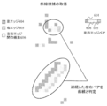
- FIG. 6 is a diagram illustrating an outline of a process of diagonal line search illustrated in FIG. 5.
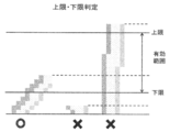
- FIG. 6 is a diagram for describing narrowing down (selection) of diagonal line candidates in the diagonal line determination shown in FIG. 5. It is a figure for explaining cooperation with other systems giving an opportunity of processing of regulation release sign detection.
- the object of the present embodiment is to perform detection in accordance with the design of the regulation release in the sign detection processing, and to erroneously determine a pattern such as a tree or a telephone pole. It is an object of the present invention to provide a camera device capable of suppressing the above.
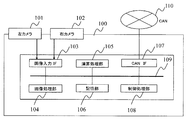
- FIG. 1 is a block diagram showing an overall configuration of a vehicle-mounted stereo camera device 100 (camera device) according to the present embodiment.
- the in-vehicle stereo camera device 100 of the present embodiment is a device mounted on a vehicle and recognizing an environment outside the vehicle based on image information of a shooting target area in front of the vehicle.
- the in-vehicle stereo camera device 100 recognizes, for example, white lines on roads, pedestrians, vehicles, other three-dimensional objects, signals, signs, lighting lamps, and the like, and brakes a vehicle (own vehicle) equipped with the stereo camera device. Perform steering and other adjustments.
- the in-vehicle stereo camera device 100 has two cameras 101 and 102 arranged on the left and right for acquiring image information, and an image input interface 103 for controlling the imaging of the cameras 101 and 102 and capturing the captured image.
- the image captured through this interface is transmitted through a bus 109 and processed by the image processing unit 104 and the arithmetic processing unit 105.
- the results during the processing and the image data as the final result are stored in the storage unit 106. Note that control lines for the cameras 101 and 102 are not shown in FIG.
- the image processing unit 104 compares the first image obtained from the image sensor of the camera 101 with the second image obtained from the image sensor of the camera 102, and determines each image based on the image sensor. Correction of a device-specific deviation and image correction such as noise interpolation are performed and stored in the storage unit 106. Further, the image processing unit 104 calculates a mutually corresponding portion between the first and second images, calculates disparity information, and stores the same in the storage unit 106 as in the above.
- the arithmetic processing unit 105 uses the image and the parallax information (distance information for each point on the image) stored in the storage unit 106 to recognize various objects necessary for perceiving the environment around the vehicle.
- the various objects include a person, a car, other obstacles, a traffic light, a sign, a tail lamp and a head ride of a car, and the like. Some of these recognition results and intermediate calculation results are recorded in the storage unit 106 as in the previous case. After performing various object recognition processes on the captured image, the arithmetic processing unit 105 calculates the control of the vehicle using the recognition results.
- the control policy of the vehicle obtained as a result of the calculation and a part of the object recognition result are transmitted to the in-vehicle network CAN (Controller Area Network) through the CAN interface 107, whereby the vehicle is braked.
- the control processing unit 108 monitors whether or not each processing unit has performed an abnormal operation, whether or not an error has occurred during data transfer, and the like. ).
- the image processing unit 104 includes, via a bus 109 (internal bus), a control processing unit 108, a storage unit 106, an arithmetic processing unit 105, and an image input interface 103 (input and output between the imaging devices of the cameras 101 and 102). ), And a CAN interface 107 (input / output unit with an external vehicle-mounted network).
- the image processing unit 104, the arithmetic processing unit 105, the storage unit 106, the image input interface 103, the CAN interface 107, and the control processing unit 108 are configured by a single or a plurality of computer units.
- the storage unit 106 includes, for example, a memory that stores image information obtained by the image processing unit 104, image information created as a result of scanning by the arithmetic processing unit 105, and the like.
- the CAN interface 107 outputs information output from the in-vehicle stereo camera device 100 to another control system of the vehicle via the CAN 110.
- FIG. 2 shows a processing flow of the vehicle-mounted stereo camera device 100.
- the left and right cameras 101 and 102 capture images.
- the image processing unit 104 absorbs a peculiar habit (image distortion or the like) of the image sensor of the cameras 101 and 102.
- Image processing 205 such as correction is performed.
- the processing result is stored in the image buffer 206.
- the image buffer 206 is provided in the storage unit 106 in FIG.
- the image processing unit 104 performs parallax processing (matching) between the images, thereby performing parallax processing 207 for obtaining parallax information of the images obtained by the left and right cameras. From the parallax between the left and right images, it becomes clear where and how the point of interest on the target object corresponds to the image on the left and right cameras, and the distance to the target can be obtained by the principle of triangulation.
- the image finally obtained by the image processing 205 and the parallax processing 207 and the parallax information are stored in the storage unit 106.
- the arithmetic processing unit 105 performs various object recognition processes 209 using the stored image and the parallax information.
- the object to be recognized includes a person, a car, other three-dimensional objects, a sign, a traffic light, a tail lamp, and the like.
- the arithmetic processing unit 105 uses the recognition dictionary 210 as necessary.
- the arithmetic processing unit 105 performs the vehicle control processing 211 in consideration of the result of the object recognition and the state of the host vehicle (speed, steering angle, etc.). For example, the vehicle control process 211 issues a warning to an occupant, determines a policy of performing braking such as braking or steering angle adjustment of the own vehicle, or determines a policy of performing avoidance control of an object by that. This is the process of outputting through
- the various object recognition processing 209 and the vehicle control processing 211 are performed by the arithmetic processing unit 105 of FIG. 1 as described above, and the output to the CAN is performed by the CAN interface 107.
- Each of these processing means is composed of, for example, a single or a plurality of computer units, and is configured to be able to exchange data with each other.
- FIG. 3 shows a timing chart of the on-vehicle stereo camera device 100.
- a right image input 303 is performed. This corresponds to a process in which the camera 102 (right camera) in FIG. 2 captures an image, passes through image processing 205, and then stores the right image in the image buffer 206 by the image processing unit 104.
- the left image input 304 is performed. This corresponds to the processing from capturing the image by the camera 101 (left camera) in FIG. 2, through the image processing 205, and storing the left image in the image buffer 206 by the image processing unit 104.
- parallax processing 207 is performed.
- the image processing unit 104 reads out two images on the left and right from the image buffer 206, calculates the disparity by comparing the two images, and stores the disparity information obtained by the calculation in the storage unit 106. This is equivalent to the processing up to the storage in. At this point, the image and the parallax information are in the storage unit 106.
- the arithmetic processing unit 105 performs various object recognition processing 209, performs the vehicle control processing 211, and outputs the result to the CAN.
- FIGS. 4A to 4C are diagrams for explaining the processing flow of the sign recognition function.
- the various object recognition processing 209 includes a sign recognition processing 209a.
- the sign recognition process 209a includes a circle detection process 406 and an identification process 407.
- FIG. 4A shows a part of the image stored in the image buffer 206 after the image processing 205.
- FIG. 4B is a processing result obtained by performing image processing on the image of FIG. 4A for use in the sign recognition processing 209a, and is an image having luminance in a portion where the density change is large in the vicinity.
- FIG. 4C is an example of a basic processing flow of sign recognition.
- the circle detection process 406 is performed using the image of FIG. 4B.
- the center of the circle is obtained by the center calculation.
- the circle detection processing 406 is divided into a center estimation step 408 and a radius estimation step 409.
- the center is estimated.
- a line segment 404 is drawn from each edge in the normal direction, and a point where intersections of the line segments overlap by a certain number or more is estimated as the center 400 (FIG. 4A).
- the counting of the number of edges may be omitted from the center 400 to a predetermined radius.
- the calculation omission area can reduce the calculation load. .
- the calculation omission area may be reduced.
- detection of a sign in the shape of a circle has been described as an example, but signs such as a rectangle, an octagon, and a triangle can also be detected in the graphic detection processing described later.
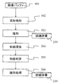
- FIG. 5 shows a processing flow for detecting a regulation release sign in the embodiment of the present invention.
- the search for the regulation release sign (regulation end sign) is performed at the timing of the sign recognition processing 209a in the various object recognition processing 209.
- a group of sign candidates called main signs such as speed signs and overtaking prohibitions is extracted by first performing graphic detection 502 from the image buffer 501 storing the image of the target frame.
- the respective patterns are cut out from the image and identification 503 is performed.
- the recognition dictionary 210 is used, and the type of the sign is identified by combining a weak classifier such as a binary discriminant tree and a strong classifier such as a nearest neighbor method or a discriminant function.
- the arithmetic processing unit 105 functions as a main marker identifying unit that identifies the main marker.
- the unique processing for the restriction release sign includes a diagonal line search 504, a diagonal line determination 505, and an identification processing 506 for the restriction release sign.
- the diagonal line search 504 is a process of detecting a diagonal line portion at the center of the restriction release marker based on an edge image obtained by extracting an edge component from a frame image to be recognized.
- the arithmetic processing unit 105 functions as a search unit that searches for an oblique line candidate from an image. By searching for a hatched line which is a characteristic design of the regulation release sign, the detection accuracy of the regulation release sign can be improved.
- the arithmetic processing unit 105 (search unit) searches for a diagonal line candidate, for example, in response to the identification of the real sign. Thereby, the oblique line of the regulation release sign co-occurring with the present sign can be detected in a timely manner.
- the specific contents of the processing are described in FIG.
- the oblique line determination 505 is a process for determining, from the detected oblique line candidates, oblique lines considered to be signs and oblique lines considered to be electric wires or pillars.
- the arithmetic processing unit 105 functions as a selection unit that selects, from the detected diagonal line candidates, a diagonal line candidate of a restriction release marker indicating release of the restriction corresponding to the real marker. This will be described later with reference to FIG.
- the identification process 506 is a process of identifying the restriction release marker from the image of the selected hatched candidate of the restriction release marker.
- the arithmetic processing unit 105 functions as a regulation release marker identification unit that performs the identification process 506.
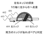
- FIG. 6A is a diagram showing an outline of a process of the oblique line search 504 (oblique line detection) shown in FIG.
- a horizontal scanning line 602 is determined for the image 601 of the target regulation release marker, and image scanning is performed in a direction 603, such as left to right.
- the image to be scanned is an edge image.
- the deregulation sign has a distinctive design in Europe, Japan and elsewhere.
- the left edge 604 and the right edge 605 of this oblique line are determined, and an edge pair is determined by utilizing the fact that the left edge and the right edge are within a certain distance.
- the arithmetic processing unit 105 scans the image in the horizontal direction, searches for a pair of a left edge and a right edge, and detects two or more pairs arranged continuously as oblique line candidates. By searching for a pair of a left edge and a right edge of at least two pixels or more, it is possible to narrow down the oblique line candidates of the restriction release sign. Note that a pair of a left edge and a right edge as oblique line candidates are continuously arranged adjacently without any gap.
- the distance (horizontal length) to be determined in the edge pair is determined by a certain range from the size of the main sign which triggered the search for the regulation release sign, or the distance to the target sign in the case of a stereo camera. It is also possible to convert using.
- the storage unit 106 stores the size of the main sign and the range of the length of the hatched horizontal direction of the restriction release sign in association with each other.
- the arithmetic processing unit 105 (search unit) determines that the distance between the left edge and the right edge is within the range of the horizontal length of the oblique line of the restriction release marker associated with the size of the main marker. Search for a pair. Thereby, the diagonal line candidates can be narrowed down by the horizontal length of the diagonal line of the restriction release marker according to the size of the real sign.
- diagonal candidates are narrowed down by the length of the continuous edge pairs.
- the narrowing down (selection) of diagonal line candidates will be described with reference to FIG.
- the output information of the diagonal line search includes the position, length, intensity, contrast ratio with the peripheral portion, color component, and line thickness of the edge pair.
- the diagonal line determination (upper limit / lower limit determination) in FIG. 7 is a process of determining a diagonal line that seems to be a design in a sign and a diagonal line component such as an electric wire or a pillar that is not related to the sign.
- the basic idea is determined by using the length and thickness of the edge pair, the contrast ratio with the periphery, the color, and the like.
- the length has an upper limit and a lower limit. Edge pairs exceeding the upper limit length are regarded as long diagonal lines such as telephone poles and are excluded, and edge pairs below the lower limit length are regarded as short diagonal lines such as patterns and excluded.
- the storage unit 106 stores the size of the permanent sign and the range of the length of the hatched vertical direction of the restriction release sign in association with each other.
- the arithmetic processing unit 105 selects a diagonal line candidate whose vertical length of the detected diagonal line candidate is within the range of the vertical length of the diagonal line of the restriction release marker associated with the size of the main sign. I do. Thereby, it is possible to prevent erroneous detection of the hatching of the regulation release sign.
- the question is how to set the upper and lower limits. This is set based on the size of the main sign which has triggered the search for the regulation release sign. In general, the size of the sign and the size range allowed for the deregulation sign are defined by the driving region and country. Using this information, the upper and lower limits of the size permitted as the deregulation sign are determined from the size of the sign. Can be estimated. As shown in FIG. 8, information on the traveling area can be obtained in cooperation with an external position information system.
- the storage unit 106 may further store information indicating the relative position of the regulation release marker with respect to the position of the main marker.
- the arithmetic processing unit 105 (processor) searches for a diagonal line candidate from an image area corresponding to the relative position of the restriction release marker with respect to the identified position of the official marker (for example, above the official marker in Japan).
- the area for searching for the hatched candidate for the regulation release sign is limited.
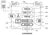
- FIG. 8 is a diagram for explaining a mechanism (configuration) for obtaining an opportunity to search for a regulation release sign in cooperation with GPS and map information.
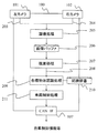
- ⁇ Image processing 805 is performed with the left camera 801 and the right camera 802 as starting points, and a parallax processing 807 detects a three-dimensional object on a side road such as a forest or a forest by looking at an area around the traveling road. Furthermore, the latitude and longitude information is obtained from the GPS, and the data of the border is stored inside the stereo camera, so that the current traveling area is determined by the country determination process. Further, information such as which country the vehicle is running, the current direction to which the vehicle is heading, and the running time zone is obtained from the running log 809.
- the external position information sensor has further high-definition map information or section information on road speed regulation, the appearance position of the sign and the switching position of the speed regulation can be known. Search is possible.
- the exposure control 811 can be performed.
- the co-occurrence status of the regulation release sign was used by changing the ratio of the processing time devoted to searching for edge pairs at the switching position of the appearance position of the sign and the speed section of the road Searching can be performed.
- the storage unit 106 stores information indicating the relative position of the restriction release sign with respect to the position of the main sign for each travel location area.
- the arithmetic processing unit 105 searches for a diagonal line candidate from the area of the image corresponding to the relative position of the regulation release sign for each travel location area with respect to the position of the identified real sign. This limits the area in which to search for a diagonal line candidate for a regulation release sign according to the traveling area. As a result, it is possible to efficiently search for a hatched candidate for a regulation release sign.
- the sign and the deregulation sign do not co-occur, and the location of the sign is different from the place of the deregulation sign.
- the arithmetic processing unit 105 search unit determines the distance from the area of the image corresponding to the position (forward) separated by the length of the section from the main sign. You may search for a diagonal line candidate.
- the detection accuracy of the regulation release sign can be improved.
- the above-described configurations, functions, and the like may be partially or entirely realized by hardware, for example, by designing an integrated circuit.
- the above-described configurations, functions, and the like may be realized by software by a processor interpreting and executing a program that realizes each function.
- Information such as a program, a table, and a file for realizing each function can be stored in a memory, a hard disk, a recording device such as an SSD (Solid State Drive), or a recording medium such as an IC card, an SD card, or a DVD.
- a circular object information acquisition unit that obtains information on a circular object from an image (circle detection unit), an identification unit that identifies a first sign for the circular object obtained by the circular object information acquisition unit, and the circular object from the image
- a search unit that searches for a tilted object around the object, information on the tilted object obtained by the search unit, and information on the first sign obtained by the identification unit, based on the second sign related to the tilted object
- a camera device comprising: a determination unit that performs a determination.
- the front search unit searches for a pair of a left edge and a right edge in a horizontal direction of the image, and the pair of the left edge and the right edge forms a slope that is continuous in a vertical direction.
- the determination unit determines the second marker with respect to the inclined object based on an upper limit and a lower limit corresponding to the first marker with respect to the circular object.
Landscapes
- Engineering & Computer Science (AREA)
- Physics & Mathematics (AREA)
- General Physics & Mathematics (AREA)
- Computer Vision & Pattern Recognition (AREA)
- Theoretical Computer Science (AREA)
- Multimedia (AREA)
- Signal Processing (AREA)
- Geometry (AREA)
- Traffic Control Systems (AREA)
- Image Analysis (AREA)
- Studio Devices (AREA)
Abstract
La présente invention concerne un dispositif de caméra au moyen duquel il est possible d'améliorer la précision de détection d'un panneau de fin de limitation. Une unité de traitement arithmétique (unité de recherche) recherche un candidat de ligne diagonale dans une image (recherche de ligne diagonale 504). L'unité de traitement arithmétique (unité de sélection) sélectionne le candidat de ligne diagonale d'un panneau de fin de limitation indiquant la fin de limitation, le candidat de ligne diagonale correspondant au panneau réel, à partir des candidats de ligne diagonale détectés (détermination de ligne diagonale 505). L'unité de traitement arithmétique (unité d'identification de panneau de fin de limitation) identifie un panneau de fin de limitation à partir des images du candidat sélectionné de ligne diagonale du panneau de fin de limitation (processus d'identification 506).
Priority Applications (2)
| Application Number | Priority Date | Filing Date | Title |
|---|---|---|---|
| CN201980063008.3A CN112789654A (zh) | 2018-10-04 | 2019-09-19 | 摄像机装置 |
| JP2020550280A JP7058753B2 (ja) | 2018-10-04 | 2019-09-19 | カメラ装置 |
Applications Claiming Priority (2)
| Application Number | Priority Date | Filing Date | Title |
|---|---|---|---|
| JP2018189385 | 2018-10-04 | ||
| JP2018-189385 | 2018-10-04 |
Publications (1)
| Publication Number | Publication Date |
|---|---|
| WO2020071132A1 true WO2020071132A1 (fr) | 2020-04-09 |
Family
ID=70055947
Family Applications (1)
| Application Number | Title | Priority Date | Filing Date |
|---|---|---|---|
| PCT/JP2019/036680 Ceased WO2020071132A1 (fr) | 2018-10-04 | 2019-09-19 | Dispositif de caméra |
Country Status (3)
| Country | Link |
|---|---|
| JP (1) | JP7058753B2 (fr) |
| CN (1) | CN112789654A (fr) |
| WO (1) | WO2020071132A1 (fr) |
Cited By (1)
| Publication number | Priority date | Publication date | Assignee | Title |
|---|---|---|---|---|
| WO2025046827A1 (fr) * | 2023-08-31 | 2025-03-06 | 株式会社Fuji | Dispositif de traitement d'images, procédé de traitement d'images et système de commande de robot |
Citations (3)
| Publication number | Priority date | Publication date | Assignee | Title |
|---|---|---|---|---|
| JP2004145501A (ja) * | 2002-10-23 | 2004-05-20 | Nissan Motor Co Ltd | 道路白線認識装置 |
| JP2015191619A (ja) * | 2014-03-28 | 2015-11-02 | 富士重工業株式会社 | 車外環境認識装置 |
| JP2018116553A (ja) * | 2017-01-19 | 2018-07-26 | 株式会社デンソー | 標識認識装置 |
Family Cites Families (4)
| Publication number | Priority date | Publication date | Assignee | Title |
|---|---|---|---|---|
| JP2570378B2 (ja) * | 1988-04-18 | 1997-01-08 | 日本電装株式会社 | 車両用標識認識装置 |
| CN101702197A (zh) * | 2009-10-26 | 2010-05-05 | 宁波大学 | 一种道路交通标志的检测方法 |
| DE102010020330A1 (de) * | 2010-05-14 | 2011-11-17 | Conti Temic Microelectronic Gmbh | Verfahren zur Erkennung von Verkehrszeichen |
| JP4940461B2 (ja) * | 2010-07-27 | 2012-05-30 | 株式会社三次元メディア | 3次元物体認識装置及び3次元物体認識方法 |
-
2019
- 2019-09-19 WO PCT/JP2019/036680 patent/WO2020071132A1/fr not_active Ceased
- 2019-09-19 JP JP2020550280A patent/JP7058753B2/ja active Active
- 2019-09-19 CN CN201980063008.3A patent/CN112789654A/zh not_active Withdrawn
Patent Citations (3)
| Publication number | Priority date | Publication date | Assignee | Title |
|---|---|---|---|---|
| JP2004145501A (ja) * | 2002-10-23 | 2004-05-20 | Nissan Motor Co Ltd | 道路白線認識装置 |
| JP2015191619A (ja) * | 2014-03-28 | 2015-11-02 | 富士重工業株式会社 | 車外環境認識装置 |
| JP2018116553A (ja) * | 2017-01-19 | 2018-07-26 | 株式会社デンソー | 標識認識装置 |
Cited By (1)
| Publication number | Priority date | Publication date | Assignee | Title |
|---|---|---|---|---|
| WO2025046827A1 (fr) * | 2023-08-31 | 2025-03-06 | 株式会社Fuji | Dispositif de traitement d'images, procédé de traitement d'images et système de commande de robot |
Also Published As
| Publication number | Publication date |
|---|---|
| CN112789654A (zh) | 2021-05-11 |
| JP7058753B2 (ja) | 2022-04-22 |
| JPWO2020071132A1 (ja) | 2021-09-24 |
Similar Documents
| Publication | Publication Date | Title |
|---|---|---|
| US8305431B2 (en) | Device intended to support the driving of a motor vehicle comprising a system capable of capturing stereoscopic images | |
| JP5679461B2 (ja) | 有効車線区分線を確定する方法及び装置 | |
| JP6313646B2 (ja) | 外界認識装置 | |
| JP6274557B2 (ja) | 移動面情報検出装置、及びこれを用いた移動体機器制御システム並びに移動面情報検出用プログラム | |
| EP3545464B1 (fr) | Dispositif de traitement d'informations, dispositif d'imagerie, système de commande d'équipement, objet mobile, procédé de traitement d'informations et support d'enregistrement lisible par ordinateur | |
| US8848980B2 (en) | Front vehicle detecting method and front vehicle detecting apparatus | |
| JP6457278B2 (ja) | 物体検出装置及び物体検出方法 | |
| JP2002319091A (ja) | 後続車両認識装置 | |
| JP5065172B2 (ja) | 車両灯火判定装置及びプログラム | |
| JP2014006885A (ja) | 段差認識装置、段差認識方法及び段差認識用プログラム | |
| WO2017122535A1 (fr) | Dispositif de détection de véhicule et dispositif de commande de distribution de lumière | |
| WO2013042675A1 (fr) | Dispositif pour détecter la lumière provenant d'un autre véhicule, programme informatique pour réaliser la détection de celle-ci et dispositif de commande des lumières d'un véhicule | |
| JP2012177997A (ja) | パッシング内容判定装置 | |
| JP7058753B2 (ja) | カメラ装置 | |
| JP2010262665A (ja) | 車載装置及び車両認識方法 | |
| KR101340014B1 (ko) | 위치 정보 제공 장치 및 방법 | |
| JP2017182139A (ja) | 判定装置、判定方法、および判定プログラム | |
| JP5957182B2 (ja) | 路面上パターン認識方法および車両用情報記録装置 | |
| JP7567689B2 (ja) | 信号認識装置 | |
| JP2020126304A (ja) | 車外物体検出装置 | |
| WO2018097269A1 (fr) | Dispositif de traitement d'informations, dispositif d'imagerie, système de commande d'équipement, objet mobile, procédé de traitement d'informations et support d'enregistrement lisible par ordinateur | |
| JP7005762B2 (ja) | カメラ装置の標識認識方法及び標識認識装置 | |
| JP2008158673A (ja) | 道路区画線認識装置 | |
| JP2021111122A (ja) | レーンマーク認識装置 | |
| WO2023021726A1 (fr) | Dispositif de reconnaissance de signe et procédé de reconnaissance de signe |
Legal Events
| Date | Code | Title | Description |
|---|---|---|---|
| 121 | Ep: the epo has been informed by wipo that ep was designated in this application |
Ref document number: 19868428 Country of ref document: EP Kind code of ref document: A1 |
|
| ENP | Entry into the national phase |
Ref document number: 2020550280 Country of ref document: JP Kind code of ref document: A |
|
| NENP | Non-entry into the national phase |
Ref country code: DE |
|
| 122 | Ep: pct application non-entry in european phase |
Ref document number: 19868428 Country of ref document: EP Kind code of ref document: A1 |