WO2020071136A1 - 振動制御装置、振動制御方法、振動制御プログラム、及び記憶媒体 - Google Patents
振動制御装置、振動制御方法、振動制御プログラム、及び記憶媒体Info
- Publication number
- WO2020071136A1 WO2020071136A1 PCT/JP2019/036711 JP2019036711W WO2020071136A1 WO 2020071136 A1 WO2020071136 A1 WO 2020071136A1 JP 2019036711 W JP2019036711 W JP 2019036711W WO 2020071136 A1 WO2020071136 A1 WO 2020071136A1
- Authority
- WO
- WIPO (PCT)
- Prior art keywords
- vibration
- music
- vibration signal
- information
- frequency
- Prior art date
- Legal status (The legal status is an assumption and is not a legal conclusion. Google has not performed a legal analysis and makes no representation as to the accuracy of the status listed.)
- Ceased
Links
Images





Classifications
-
- A—HUMAN NECESSITIES
- A61—MEDICAL OR VETERINARY SCIENCE; HYGIENE
- A61M—DEVICES FOR INTRODUCING MEDIA INTO, OR ONTO, THE BODY; DEVICES FOR TRANSDUCING BODY MEDIA OR FOR TAKING MEDIA FROM THE BODY; DEVICES FOR PRODUCING OR ENDING SLEEP OR STUPOR
- A61M21/00—Other devices or methods to cause a change in the state of consciousness; Devices for producing or ending sleep by mechanical, optical, or acoustical means, e.g. for hypnosis
- A61M21/02—Other devices or methods to cause a change in the state of consciousness; Devices for producing or ending sleep by mechanical, optical, or acoustical means, e.g. for hypnosis for inducing sleep or relaxation, e.g. by direct nerve stimulation, hypnosis, analgesia
-
- A—HUMAN NECESSITIES
- A61—MEDICAL OR VETERINARY SCIENCE; HYGIENE
- A61M—DEVICES FOR INTRODUCING MEDIA INTO, OR ONTO, THE BODY; DEVICES FOR TRANSDUCING BODY MEDIA OR FOR TAKING MEDIA FROM THE BODY; DEVICES FOR PRODUCING OR ENDING SLEEP OR STUPOR
- A61M21/00—Other devices or methods to cause a change in the state of consciousness; Devices for producing or ending sleep by mechanical, optical, or acoustical means, e.g. for hypnosis
-
- A—HUMAN NECESSITIES
- A61—MEDICAL OR VETERINARY SCIENCE; HYGIENE
- A61B—DIAGNOSIS; SURGERY; IDENTIFICATION
- A61B5/00—Measuring for diagnostic purposes; Identification of persons
- A61B5/02—Detecting, measuring or recording for evaluating the cardiovascular system, e.g. pulse, heart rate, blood pressure or blood flow
- A61B5/024—Measuring pulse rate or heart rate
-
- A—HUMAN NECESSITIES
- A61—MEDICAL OR VETERINARY SCIENCE; HYGIENE
- A61B—DIAGNOSIS; SURGERY; IDENTIFICATION
- A61B5/00—Measuring for diagnostic purposes; Identification of persons
- A61B5/08—Measuring devices for evaluating the respiratory organs
- A61B5/0816—Measuring devices for examining respiratory frequency
-
- A—HUMAN NECESSITIES
- A61—MEDICAL OR VETERINARY SCIENCE; HYGIENE
- A61B—DIAGNOSIS; SURGERY; IDENTIFICATION
- A61B5/00—Measuring for diagnostic purposes; Identification of persons
- A61B5/68—Arrangements of detecting, measuring or recording means, e.g. sensors, in relation to patient
- A61B5/6887—Arrangements of detecting, measuring or recording means, e.g. sensors, in relation to patient mounted on external non-worn devices, e.g. non-medical devices
- A61B5/6891—Furniture
-
- A—HUMAN NECESSITIES
- A61—MEDICAL OR VETERINARY SCIENCE; HYGIENE
- A61M—DEVICES FOR INTRODUCING MEDIA INTO, OR ONTO, THE BODY; DEVICES FOR TRANSDUCING BODY MEDIA OR FOR TAKING MEDIA FROM THE BODY; DEVICES FOR PRODUCING OR ENDING SLEEP OR STUPOR
- A61M21/00—Other devices or methods to cause a change in the state of consciousness; Devices for producing or ending sleep by mechanical, optical, or acoustical means, e.g. for hypnosis
- A61M2021/0005—Other devices or methods to cause a change in the state of consciousness; Devices for producing or ending sleep by mechanical, optical, or acoustical means, e.g. for hypnosis by the use of a particular sense, or stimulus
- A61M2021/0022—Other devices or methods to cause a change in the state of consciousness; Devices for producing or ending sleep by mechanical, optical, or acoustical means, e.g. for hypnosis by the use of a particular sense, or stimulus by the tactile sense, e.g. vibrations
-
- A—HUMAN NECESSITIES
- A61—MEDICAL OR VETERINARY SCIENCE; HYGIENE
- A61M—DEVICES FOR INTRODUCING MEDIA INTO, OR ONTO, THE BODY; DEVICES FOR TRANSDUCING BODY MEDIA OR FOR TAKING MEDIA FROM THE BODY; DEVICES FOR PRODUCING OR ENDING SLEEP OR STUPOR
- A61M21/00—Other devices or methods to cause a change in the state of consciousness; Devices for producing or ending sleep by mechanical, optical, or acoustical means, e.g. for hypnosis
- A61M2021/0005—Other devices or methods to cause a change in the state of consciousness; Devices for producing or ending sleep by mechanical, optical, or acoustical means, e.g. for hypnosis by the use of a particular sense, or stimulus
- A61M2021/0027—Other devices or methods to cause a change in the state of consciousness; Devices for producing or ending sleep by mechanical, optical, or acoustical means, e.g. for hypnosis by the use of a particular sense, or stimulus by the hearing sense
-
- A—HUMAN NECESSITIES
- A61—MEDICAL OR VETERINARY SCIENCE; HYGIENE
- A61M—DEVICES FOR INTRODUCING MEDIA INTO, OR ONTO, THE BODY; DEVICES FOR TRANSDUCING BODY MEDIA OR FOR TAKING MEDIA FROM THE BODY; DEVICES FOR PRODUCING OR ENDING SLEEP OR STUPOR
- A61M21/00—Other devices or methods to cause a change in the state of consciousness; Devices for producing or ending sleep by mechanical, optical, or acoustical means, e.g. for hypnosis
- A61M2021/0005—Other devices or methods to cause a change in the state of consciousness; Devices for producing or ending sleep by mechanical, optical, or acoustical means, e.g. for hypnosis by the use of a particular sense, or stimulus
- A61M2021/0083—Other devices or methods to cause a change in the state of consciousness; Devices for producing or ending sleep by mechanical, optical, or acoustical means, e.g. for hypnosis by the use of a particular sense, or stimulus especially for waking up
-
- A—HUMAN NECESSITIES
- A61—MEDICAL OR VETERINARY SCIENCE; HYGIENE
- A61M—DEVICES FOR INTRODUCING MEDIA INTO, OR ONTO, THE BODY; DEVICES FOR TRANSDUCING BODY MEDIA OR FOR TAKING MEDIA FROM THE BODY; DEVICES FOR PRODUCING OR ENDING SLEEP OR STUPOR
- A61M2205/00—General characteristics of the apparatus
- A61M2205/33—Controlling, regulating or measuring
- A61M2205/3375—Acoustical, e.g. ultrasonic, measuring means
-
- A—HUMAN NECESSITIES
- A61—MEDICAL OR VETERINARY SCIENCE; HYGIENE
- A61M—DEVICES FOR INTRODUCING MEDIA INTO, OR ONTO, THE BODY; DEVICES FOR TRANSDUCING BODY MEDIA OR FOR TAKING MEDIA FROM THE BODY; DEVICES FOR PRODUCING OR ENDING SLEEP OR STUPOR
- A61M2205/00—General characteristics of the apparatus
- A61M2205/58—Means for facilitating use, e.g. by people with impaired vision
- A61M2205/582—Means for facilitating use, e.g. by people with impaired vision by tactile feedback
-
- B—PERFORMING OPERATIONS; TRANSPORTING
- B60—VEHICLES IN GENERAL
- B60N—SEATS SPECIALLY ADAPTED FOR VEHICLES; VEHICLE PASSENGER ACCOMMODATION NOT OTHERWISE PROVIDED FOR
- B60N2/00—Seats specially adapted for vehicles; Arrangement or mounting of seats in vehicles
- B60N2/90—Details or parts not otherwise provided for
-
- B—PERFORMING OPERATIONS; TRANSPORTING
- B60—VEHICLES IN GENERAL
- B60N—SEATS SPECIALLY ADAPTED FOR VEHICLES; VEHICLE PASSENGER ACCOMMODATION NOT OTHERWISE PROVIDED FOR
- B60N2/00—Seats specially adapted for vehicles; Arrangement or mounting of seats in vehicles
- B60N2/90—Details or parts not otherwise provided for
- B60N2002/981—Warning systems, e.g. the seat or seat parts vibrates to warn the passenger when facing a danger
-
- H—ELECTRICITY
- H04—ELECTRIC COMMUNICATION TECHNIQUE
- H04R—LOUDSPEAKERS, MICROPHONES, GRAMOPHONE PICK-UPS OR LIKE ACOUSTIC ELECTROMECHANICAL TRANSDUCERS; ELECTRIC HEARING AIDS; PUBLIC ADDRESS SYSTEMS
- H04R2499/00—Aspects covered by H04R or H04S not otherwise provided for in their subgroups
- H04R2499/10—General applications
- H04R2499/13—Acoustic transducers and sound field adaptation in vehicles
-
- H—ELECTRICITY
- H04—ELECTRIC COMMUNICATION TECHNIQUE
- H04R—LOUDSPEAKERS, MICROPHONES, GRAMOPHONE PICK-UPS OR LIKE ACOUSTIC ELECTROMECHANICAL TRANSDUCERS; ELECTRIC HEARING AIDS; PUBLIC ADDRESS SYSTEMS
- H04R5/00—Stereophonic arrangements
- H04R5/02—Spatial or constructional arrangements of loudspeakers
- H04R5/023—Spatial or constructional arrangements of loudspeakers in a chair, pillow
Definitions
- the present invention relates to a vibration control device that controls a vibration device, a vibration control method, a vibration control program, and a storage medium.
- Patent Document 1 Conventionally, there is known a technique in which a vibrating device built in a sheet of a moving body is vibrated in accordance with music played by an audio device to give a user a bodily sensation (for example, see Patent Document 1).
- the technique described in Patent Document 1 is configured to vibrate a vibration device with a signal obtained by amplifying a low-frequency component of music being reproduced. By generating such vibrations and causing the music to have a bodily sensation, entertainment can be enhanced.
- by causing the user to experience vibration as a stimulus it is possible to obtain an effect of awakening a drowsy user or an effect of relaxing an excited user.
- an object of the present invention is to provide a vibration control apparatus, a vibration control method, and a vibration control method capable of generating a vibration that can obtain a desired awakening effect and / or a relaxing effect irrespective of the content thereof, while responding to music being reproduced.
- Providing a control program and a storage medium is an example.
- a vibration control device of the present invention is a vibration control device that controls a vibration device that generates vibration according to music being played and stimulates a user, A vibration signal acquisition unit that acquires a vibration signal representing the vibration in which the intensity of the stimulus falls within a predetermined stimulus intensity range, and an output unit that outputs the vibration signal acquired by the vibration signal acquisition unit to the vibration device, It is characterized by having.
- a vibration control method of the present invention is a vibration control method for controlling a vibration device that generates vibration according to music being reproduced and stimulates a user.
- a vibration control program of the present invention causes a computer to execute the above-described vibration control method of the present invention.
- a storage medium of the present invention stores the above-described vibration control program of the present invention.
- FIG. 2 is a schematic block diagram illustrating a vibration control device according to the first embodiment, which is mounted on a moving body.
- 3 is a flowchart illustrating a process flow of a vibration control method executed by the vibration control device illustrated in FIG. 1.
- FIG. 9 is a schematic block diagram illustrating a vibration control device according to a second embodiment, which is mounted on a moving body.
- FIG. 4 is a schematic diagram showing a data structure of music / vibration correspondence data shown in FIG. 3 in a table format. 4 is a flowchart illustrating a process flow of a vibration control method executed by the vibration control device illustrated in FIG. 3.
- FIG. 11 is a schematic block diagram illustrating a vibration control device according to a third embodiment, which is mounted on a moving body.
- FIG. 7 is a schematic diagram showing a data structure of the map data shown in FIG. 6 in a table format.
- FIG. 8 is a schematic diagram showing a data structure shown in a table format in FIG. 7 in a map format.
- 7 is a flowchart illustrating a process flow of a vibration control method executed by the vibration control device illustrated in FIG. 6.
- FIG. 9 is a schematic diagram showing, in a table form, a data structure of a modification example of the data structure of the map data shown in FIGS. 7 and 8.
- FIG. 11 is a schematic diagram showing a data structure shown in a table format in FIG. 10 in a map format.
- a vibration control device is a vibration control device that controls a vibration device that generates vibration according to music being played and provides a stimulus to a user, and includes a vibration signal acquisition unit, an output unit, , Is provided.
- the vibration signal acquiring unit acquires a vibration signal representing a vibration in which the stimulus intensity falls within a predetermined stimulus intensity range.
- the output unit outputs the vibration signal obtained by the vibration signal obtaining unit to the vibration device.
- a vibration signal representing a vibration in which the stimulus intensity falls within a predetermined stimulus intensity range is obtained while outputting the vibration signal to the vibration device, while responding to the music being reproduced. Therefore, the stimulus intensity range is set to a desired range in which a desired awakening effect and / or a relaxing effect can be obtained, and such an effect can be obtained irrespective of the content of the music being reproduced. Vibration can be generated in the vibration device. As described above, according to the vibration control device of the present embodiment, it is possible to generate a vibration that can obtain a desired awakening effect and / or a relaxing effect irrespective of the content, while responding to the music being reproduced.
- the vibration signal acquisition unit acquires, as a vibration signal, a signal representing a vibration whose vibration frequency falls within a predetermined frequency range.
- a frequency range of 20 Hz to 200 Hz is an example of a frequency range suitable for providing an awakening effect and / or a relaxing effect.
- the vibration frequency of the vibration represented by the vibration signal acquired by the vibration signal acquisition unit is suppressed to such a frequency range, and the vibration that appropriately provides the awakening effect and / or the relaxing effect is generated. be able to.
- the vibration signal obtaining unit obtains, as a vibration signal, a signal representing a vibration corresponding to at least one of a music tempo and a frequency of a sound constituting a chord included in the music.
- the vibration of the vibration signal acquired by the vibration signal acquisition unit is in accordance with the tempo of the music being reproduced or the frequency of the sound constituting the chord, the vibration is generated by the vibration device. It is difficult for the vibration to spoil the taste of the music being played. As described above, according to the present embodiment, it is possible to generate the vibration for obtaining the awakening effect and / or the relaxing effect without impairing the taste of the music being reproduced.
- the vibration signal obtaining unit obtains, as a vibration signal, a signal representing a vibration corresponding to the music tempo, wherein the frequency of occurrence of the vibration falls within a predetermined frequency range as the stimulus intensity range. I do.
- the frequency of occurrence of the vibration determined according to the tempo of the music being played back can be adopted as an index indicating the intensity of the stimulus given by the vibration.
- the frequency of occurrence is adopted as such an index, and the stimulus intensity range is specifically set as the frequency range. Can be generated.
- the vibration signal acquiring unit acquires, as a vibration signal, a signal representing a vibration corresponding to a frequency of a sound constituting a music code.
- the vibration for obtaining the awakening effect and / or the relaxing effect is generated without impairing the taste of the music being reproduced. Can be done.
- the vibration signal obtaining unit obtains, as a vibration signal, a signal representing a vibration whose vibration amount falls within a predetermined vibration amount range as a stimulus intensity range.
- the amount of vibration can be adopted as an index indicating the intensity of the stimulus given by the vibration.
- the vibration amount is employed as such an index, and the stimulus intensity range is specifically set as the vibration amount range, so that the vibration that provides the desired awakening effect and / or relaxation effect can be obtained. It can be generated effectively.
- the vibration control device of the present embodiment includes a first setting unit that sets a stimulus intensity range in response to a user operation. Then, the vibration signal acquisition unit acquires, as a vibration signal, a signal representing a vibration in which the stimulus intensity falls within the stimulus intensity range set by the first setting unit.
- the user can adjust the stimulus intensity range, that is, the stimulus intensity given by the vibration, to the intensity desired by the user via the first setting unit. This makes it possible to effectively generate a vibration that provides a desired awakening effect and / or a relaxing effect.
- the vibration control device includes a biological information acquisition unit and a second setting unit.
- the biometric information acquisition unit acquires biometric information indicating a biometric state of the user.
- the second setting unit sets a stimulus intensity range based on the biological information acquired by the biological information acquiring unit.
- the vibration signal acquiring unit acquires, as a vibration signal, a signal representing a vibration in which the stimulus intensity falls within the stimulus intensity range set by the second setting unit.
- the vibration control device of the present embodiment includes a detection unit and a generation unit.
- the detection unit detects, from the music, at least one of a tempo of the music and a frequency of a sound constituting a chord included in the music as a music element.
- the generation unit generates a vibration signal based on the music element detected by the detection unit. Then, the vibration signal acquisition unit acquires the vibration signal generated by the generation unit.
- vibration for obtaining an awakening effect and / or a relaxing effect is further enhanced in the taste of the music being reproduced. It can be generated without loss.
- a vibration control method is a vibration control method for controlling a vibration device that generates vibration according to music being reproduced and stimulates a user, and includes a vibration signal obtaining step, And a process.
- the vibration signal obtaining step is a step of obtaining a vibration signal representing a vibration in which the stimulus intensity falls within a predetermined stimulus intensity range.
- the output step is a step of outputting the vibration signal obtained in the vibration signal obtaining step to the vibration device.
- a vibration signal representing a vibration in which the stimulus intensity falls within a predetermined stimulus intensity range is obtained while outputting the vibration signal to the vibration device, while responding to the music being reproduced. Therefore, the stimulus intensity range is set to a desired range in which a desired awakening effect and / or a relaxing effect can be obtained, and such an effect can be obtained irrespective of the content of the music being reproduced. Vibration can be generated in the vibration device. As described above, according to the vibration control method of the present embodiment, it is possible to generate a vibration that can provide a desired awakening effect and / or a relaxing effect irrespective of the content, while responding to the music being reproduced.
- the vibration control program according to the embodiment of the present invention is a program that causes a computer to execute the above-described vibration control method.
- vibration control program of the present embodiment by causing the computer to execute the above-described vibration control method, a desired awakening effect and / or a relaxing effect can be obtained regardless of the content while playing the music being played. Vibration can be generated.
- the storage medium according to the embodiment of the present invention stores the above-described vibration control program.
- the desired arousal effect and the desired awakening effect can be achieved regardless of the content while playing the music being played. Vibrations that provide a relaxing effect can be generated.
- FIG. 1 is a schematic block diagram showing the vibration control device according to the first embodiment, which is mounted on a moving body.
- the moving body is a passenger car, and the vibration control device 110, the vibration device 120, and the car stereo 130 are mounted.
- the car stereo 130 reproduces music inside the moving body, and includes a music information output unit 131 and a vehicle speaker 132.
- the music information output unit 131 outputs, to the vehicle speaker 132, music information obtained from a medium such as a CD (compact @ disc) or from a network via wireless communication.
- Vehicle speaker 132 generates music represented by the music information.
- the music information output unit 131 also outputs music information indicating the music being reproduced to the vibration control device 110.
- the music information output to the vibration control device 110 may be digital information such as MIDI (Musical Instrument Digital Interface), I2S (Inter-IC Sound), or analog information.
- the vibration device 120 is a device that is embedded in the back plate 141 of the seat 140 of the moving body and generates vibration according to the music being reproduced to stimulate the user.
- the vibration device 120 receives a vibration signal representing vibration from the vibration control device 110, and generates vibration represented by the vibration signal.
- the power of the vibrating device 120 is basically turned on at the same time as the music playback on the car stereo 130, and is turned off when the music playback on the car stereo 130 is completed.
- an on / off instruction is given by the user via the operation input unit 113 described later during music playback, the power is turned on / off in accordance with the instruction.
- the vibration control device 110 controls the vibration device 120 by outputting the above-described vibration signal, and is built in a computer mounted on a moving body.
- the vibration control device 110 includes a vibration signal acquisition unit 111, an output unit 112, an operation input unit 113, a first setting unit 114, a biological information acquisition unit 115, a second setting unit 116, a detection unit 117, and a generation unit 118. I have.
- the vibration signal acquiring unit 111 acquires a vibration signal representing a vibration in which the intensity of the generated stimulus falls within a predetermined stimulus intensity range.
- the vibration signal is internally generated in the vibration control device 110, and the vibration signal acquisition unit 111 acquires the internally generated vibration signal.
- the output unit 112 outputs the vibration signal acquired by the vibration signal acquisition unit 111 to the vibration device 120.
- the operation input unit 113 receives an operation from the user for turning on / off the vibration device 120 and increasing / decreasing the intensity of the vibration stimulus generated by the vibration device 120.
- the output unit 112 stops outputting the vibration signal to the vibration device 120 and turns off the power of the vibration device 120.
- the output unit 112 turns on the power of the vibration device 120 and outputs the vibration signal. To resume.
- the first setting unit 114 sets the stimulus intensity range according to the increase / decrease operation received by the operation input unit 113.
- the vibration signal obtaining unit 111 obtains a vibration signal representing intermittent vibration according to the tempo of the music being reproduced.
- two of the occurrence frequency which is the number of occurrences of vibration per unit time, and the amount of vibration corresponding to the amplitude of the vibration are adopted as indices indicating the intensity of the stimulus. Therefore, the first setting unit 114 includes a frequency range setting unit 114a that sets a frequency range as a stimulus intensity range, and a vibration amount range setting unit 114b that sets a vibration amount range as a stimulus intensity range. .
- the frequency range setting unit 114a in the first setting unit 114 sets the frequency range by shifting the frequency range in accordance with the increase / decrease operation received by the operation input unit 113.
- the vibration amount range setting unit 114b in the first setting unit 114 sets the vibration amount range by shifting and adjusting the vibration amount range in accordance with the increase / decrease operation received by the operation input unit 113.
- the biometric information acquisition unit 115 acquires biometric information representing a user's biometric state. Specifically, the biological information acquisition unit 115 monitors the user's heartbeat, brain wave, respiratory rate, eye movement, blinking, gaze direction, and the like, using various sensors installed inside the moving object. Then, it detects and acquires the biological state of the sleepy state in which the user is drowsy, the normal awake state, and the excited state.
- the awake state referred to here corresponds to a sedation state with respect to the excited state.
- the second setting unit 116 sets a frequency range and a vibration amount range as a stimulus intensity range based on the biological state acquired by the biological information acquiring unit 115, and includes a frequency range setting unit 116a and a vibration amount range.
- a setting unit 116b sets a frequency range and a vibration amount range as a stimulus intensity range based on the biological state acquired by the biological information acquiring unit 115, and includes a frequency range setting unit 116a and a vibration amount range.
- the frequency range setting unit 116a in the second setting unit 116 sets a frequency range according to the acquired biological information.
- the frequency range is set to an awakening frequency range corresponding to a higher occurrence frequency of applying a stronger stimulus to encourage arousal.
- the frequency range is set to a normal frequency range corresponding to a normal occurrence frequency that gives a moderate stimulus.
- the frequency range is set to a relaxation frequency range corresponding to a lower occurrence frequency of applying a weaker stimulus for relaxation.
- the vibration amount range setting unit 116b in the second setting unit 116 sets the vibration amount range according to the acquired biological information.
- the vibration amount range is set to an awakening vibration amount range corresponding to a large vibration amount that gives a stronger stimulus to encourage awakening.
- the vibration amount range is set to a normal vibration amount range corresponding to a normal vibration amount that gives a moderate stimulus.
- the vibration amount range is set to a relaxation vibration amount range corresponding to a small vibration amount that gives a weak stimulus for relaxation.
- the detection unit 117 Based on the music information sent from the music information output unit 131 of the car stereo 130, the detection unit 117 extracts the tempo of the music, the frequency of the sound constituting the music code, and the music The three music elements of the sound intensity at are detected.
- the detection of the tempo is based on a known BPM (Beats @ Per @ Minute) detection technique.
- the frequency of the sound that constitutes the chord is detected by a known chord analysis technique.
- the strength of the sound is obtained directly from the music information.
- the generation unit 118 generates a vibration signal based on three music elements: the tempo detected by the detection unit 117, the frequency of the sound that forms the chord, and the strength of the sound.
- the generator first sets the frequency of occurrence of the vibration represented by the vibration signal based on the tempo, and sets the frequency of the vibration based on the frequency of the sounds that make up the chord.
- the frequency of occurrence is set to be the same as the tempo, an integer multiple thereof, or a fraction of an integer. Further, the vibration amount is set based on the strength of the sound represented by the music information.
- the frequency is basically set to the same frequency as the frequency of the sound constituting the chord. At this time, the frequency is adjusted so that the set frequency falls within a predetermined frequency range.
- a frequency range of 20 Hz to 200 Hz is set as an example of a frequency range suitable for providing an awakening effect and / or a relaxing effect. If the frequency set based on the code does not fall within this frequency range, the frequency is adjusted to fall within this frequency range by changing the octave or the like. This adjustment may be performed by frequency conversion using a conversion LUT (Lookup table).
- the generation unit 118 adjusts the occurrence frequency once set as described above so as to be within the frequency range set by the second setting unit 116 based on the biological information.
- the frequency range is adjusted by a user operation in the first setting unit 114, the occurrence frequency is increased or decreased so as to be within the adjusted frequency range.
- the generation unit 118 increases or decreases the vibration amount once set as described above so as to fall within the vibration amount range set by the second setting unit 116 based on the biological information.
- the vibration amount range is adjusted by a user operation in the first setting unit 114, the vibration amount is increased or decreased so as to be within the adjusted vibration amount range.
- the generation of the vibration signal by the generation unit 118 is performed based on the tempo of the music being reproduced, the frequency of the sound constituting the chord, and the strength of the sound.
- a vibration signal arranged based on a music element may be generated.
- the music elements for the arrangement include a tone color, a duration of one sound, a fluctuation in sound pressure level, a speed of a sound rising (attack feeling), and the like.
- the vibration signal acquisition unit 111 acquires the vibration signal thus generated by the generation unit 118, and the output unit 112 outputs the acquired vibration signal to the vibration device 120.
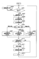
- FIG. 2 is a flowchart showing a flow of processing of a vibration control method executed by the vibration control device shown in FIG.
- the generation unit 118 determines whether or not the power of the vibration device 120 has been turned on / off with respect to the operation input unit 113 after the start of music playback (step S101). In particular, when the operation is not performed or the ON operation is performed (ON determination in step S101), the output unit 112 is turned ON if the power of the vibration device 120 is OFF at this time (step S102). ). In step S102, if the power of the vibration device 120 is in the ON state at this point, the process proceeds to the next step S104 without performing any particular process.
- step S101 when the off operation is performed (off determination in step S101), if the power of the vibration device 120 is on at this time, the output unit 112 is turned off (step S103), and the process returns to step S101.
- step S103 if the power of the vibration device 120 is off at this point, the process returns to step S101 without performing any particular process.
- step S104 the detection unit 117 acquires music information for one measure of the music being reproduced from the music information output unit 131 of the car stereo 130. Subsequently, the detection unit 117 detects the tempo, the frequency of the sound that forms the chord, and the strength of the sound based on the acquired music information (step S105).
- the biological information acquisition unit 115 acquires biological information indicating whether the biological state of the user is a sleepy state, a normal awake state, or an excited state (step S106).
- the second setting unit 116 determines whether the biological state represented by the obtained biological information is a sleepy state, an awake state, or an excited state (step S107).
- the frequency range setting unit 116a of the second setting unit 116 sets the frequency range to the awakening frequency range (step S108). Further, the vibration amount surrounding setting section 116b sets the vibration amount range to the awake vibration amount range (step S109).
- the frequency range setting unit 116a of the second setting unit 116 sets the frequency range to the normal frequency range (step S110). Further, the vibration amount surrounding setting section 116b sets the vibration amount range to the normal vibration amount range (step S111).
- the frequency range setting unit 116a of the second setting unit 116 sets the frequency range to the relaxed frequency range (step S112). Further, the vibration amount surrounding setting section 116b sets the vibration amount range to the relaxed vibration amount range (step S113).
- the generation unit 118 determines whether or not the operation input unit 113 has been subjected to the stimulus intensity adjustment operation after the start of music reproduction. (Step S114).
- step S114 If there is an adjustment operation (Yes in step S114), the frequency range setting unit 114a of the first setting unit 114 increases or decreases the set frequency range according to the operation amount (step S115). Further, the vibration amount surrounding setting unit 114b increases or decreases the vibration amount range according to the operation amount (step S116).
- step S115 and step S116 are omitted, and the process proceeds to the next step S117.
- step S117 based on the tempo obtained in the processing up to this point, the frequency of the sound constituting the chord, the intensity of the sound, the frequency range, and the vibration amount range, the generation unit 118 converts the music information for one measure into Generate a corresponding vibration signal. That is, the frequency of occurrence falls within the frequency range according to the tempo of the measure, the frequency falls within the frequency range of 20 Hz to 200 Hz according to the chord of the measure, and the amount of vibration is the intensity of the sound of the measure. , A vibration signal representing a vibration falling within the vibration amount range is generated.
- the vibration signal acquisition unit 111 acquires the vibration signal for one bar generated in this way (step S118), and the output unit 112 outputs the vibration signal to the vibration device 120 (step S119). Thereafter, the process returns to step S101, and the subsequent processes are repeated.
- the music information of the music being reproduced is acquired in units of one bar, and the corresponding vibration signal is generated in units of one bar.
- the processing break is limited to one bar. Instead, the processing may be performed in arbitrary units. For example, music information for a unit time may be acquired, and a corresponding vibration signal may be generated at unit time intervals.
- a vibration control program for causing a computer to execute the vibration control method represented by the flowchart in FIG. 2 is stored in a storage medium of some computer mounted on the moving body.
- the storage medium for storing the vibration control program is not limited to a storage medium of any computer mounted on the moving body, but is installed in a known portable storage medium or a server connected to the computer via a network. Storage medium may be used.
- the vibration control device 110 According to the vibration control device 110, the vibration control method, the vibration control program, and the storage medium of the first embodiment described above, the following effects can be obtained.
- a vibration signal representing a vibration in which the stimulus intensity falls within a predetermined stimulus intensity range is obtained while outputting the vibration signal to the vibration device 120 while responding to the music being reproduced. Therefore, the stimulus intensity range is set to a desired range in which a desired awakening effect and / or a relaxing effect can be obtained, and such an effect can be obtained irrespective of the content of the music being reproduced. Vibration can be generated in the vibration device 120. As described above, according to the vibration control device 110 of the present embodiment, it is possible to generate a vibration that can obtain a desired awakening effect and / or a relaxing effect irrespective of the content, while responding to the music being reproduced.
- the vibration device 120 and the vibration control device 110 mounted on the moving body are illustrated, but the installation place of the vibration device 120 and the vibration control device 110 is not limited to the moving body.
- the vibration device 120 and the vibration control device 110 may be installed on a seat placed in a movie theater or a general residence, for example, as long as they can provide a user with stimulation by vibration. Can be set to
- the installation position of the vibration device 120 is not limited to the position inside the back plate 141 of the seat 140 as in the present embodiment, but may be any position that can provide stimulation to the user. Can be set to
- the vibration signal acquiring unit 111 acquires a signal representing a vibration whose vibration frequency falls within the frequency range of 20 Hz to 200 Hz as a vibration signal.
- the above-mentioned frequency range of 20 Hz to 200 Hz is an example of a frequency range suitable for providing the arousal effect and / or the relaxing effect. This is because vibrations having a frequency lower than 20 Hz resonate with the internal organs of a human, and vibrations having a frequency higher than 200 Hz cause the human to feel sizzling, and the discomfort is relatively high.
- the vibration frequency of the vibration represented by the vibration signal acquired by the vibration signal acquiring unit 111 is suppressed to such a frequency range, and the vibration that appropriately provides the awakening effect and / or the relaxing effect is generated. Can be done.
- the frequency range for containing the frequency of the vibration is not limited to the range of 20 Hz to 200 Hz, and may be appropriately set as long as it is a frequency range suitable for producing the arousal effect and / or the relaxing effect.
- the vibration signal obtaining unit 111 obtains a signal representing a vibration corresponding to the tempo of music, the frequency of a sound constituting a chord included in the music, and the strength of the sound as a vibration signal.
- the vibration of the vibration signal acquired by the vibration signal acquisition unit 111 depends on the tempo of the music being reproduced, the frequency of the sound that forms the chord, and the strength of the sound. In addition, it is difficult for the vibration generated by the vibration device 120 to impair the music being reproduced. As described above, according to the present embodiment, it is possible to generate the vibration for obtaining the awakening effect and / or the relaxing effect without impairing the taste of the music being reproduced.
- the vibration represented by the vibration signal may be based on only the tempo or only the frequency of the sound constituting the chord, as long as the vibration corresponds to at least one of the tempo and the frequency of the sound constituting the chord.
- an element of vibration determined by an element other than the tempo and an element of vibration determined by an element other than the frequency of the sound constituting the chord are set according to some setting rules.
- the vibration signal acquisition unit 111 uses a signal representing a vibration corresponding to the music tempo, in which the frequency of occurrence of the vibration falls within a predetermined frequency range as the stimulus intensity range, as a vibration signal. get.
- the frequency of occurrence of the vibration determined according to the tempo of the music being played back can be adopted as an index indicating the intensity of the stimulus given by the vibration.
- the frequency of occurrence is adopted as such an index, and the stimulus intensity range is specifically set as the frequency range. Can be generated.
- the vibration signal acquiring unit 111 acquires a signal representing a vibration corresponding to a frequency of a sound constituting a music code as a vibration signal.
- the vibration for obtaining the awakening effect and / or the relaxing effect is generated without impairing the taste of the music being reproduced. Can be done.
- the vibration signal acquiring unit 111 acquires, as a vibration signal, a signal representing a vibration whose vibration amount falls within a predetermined vibration amount range as a stimulus intensity range.
- the amount of vibration can be adopted as an index indicating the intensity of the stimulus given by the vibration.
- the vibration amount is employed as such an index, and the stimulus intensity range is specifically set as the vibration amount range. It can be generated effectively.
- the stimulus intensity ranges two types, i.e., a frequency range and a vibration amount range, are set as the stimulus intensity ranges.
- the stimulus intensity range mentioned here may be only one of the frequency range and the vibration amount range, or use any index indicating the intensity of the vibration stimulus other than the occurrence frequency and the vibration amount. May be within the range.
- the vibration control device 110 includes the first setting unit 114 that sets a stimulus intensity range in response to a user operation. Then, the vibration signal acquisition unit 111 acquires, as a vibration signal, a signal indicating a vibration in which the stimulus intensity falls within the stimulus intensity range set by the first setting unit 114.
- the user can adjust the stimulus intensity range, that is, the intensity of the stimulus given by the vibration, to the intensity desired by the user via the first setting unit 114.
- the stimulus intensity range that is, the intensity of the stimulus given by the vibration
- the vibration control device 110 includes a biological information acquisition unit 115 and a second setting unit 116.
- the biometric information acquisition unit 115 acquires biometric information indicating a biometric state of the user.
- the second setting unit 116 sets a stimulus intensity range based on the biological information acquired by the biological information acquiring unit 115.
- the vibration signal acquiring unit 111 acquires, as a vibration signal, a signal indicating a vibration in which the stimulus intensity falls within the stimulus intensity range set by the second setting unit 116.
- an appropriate stimulus according to the biological condition is given to the user, so that it is possible to generate a vibration that appropriately obtains a desired awakening effect and / or a relaxing effect.
- the vibration control includes both the first setting unit 114 that sets the stimulus intensity range in response to the operation of the user and the second setting unit 116 that sets the stimulus intensity range based on the biological information.
- Apparatus 110 is illustrated.
- the vibration control device is not limited to this, and may be a device including only one of the first setting unit 114 and the second setting unit 116 described above.
- the first setting unit 114 for adjusting the stimulus intensity to the intensity desired by the user is illustrated as an example of the part for setting the stimulus intensity range in response to the operation of the user.
- the region for setting the stimulus intensity range in response to the operation of the user is not limited to this, and the stimulus intensity range is selectively selected from a plurality of predetermined range candidates, similarly to the second setting unit 116 described above. May be set.
- the vibration control device 110 includes the detection unit 117 and the generation unit 118.
- the detection unit 117 detects, as music elements, the tempo of the music, the frequency of a sound constituting a chord included in the music, and the strength of the sound, from the music.
- the generation unit 118 generates a vibration signal based on the music element detected by the detection unit 117. Then, the vibration signal acquisition unit 111 acquires the vibration signal generated by the generation unit 118.
- vibration for obtaining an awakening effect and / or a relaxing effect is further added to the taste of the music being reproduced. It can be generated without loss.
- the second setting unit 116 sets the stimulus intensity range to be stronger when the biological information indicates the drowsy state than when the biological information indicates the awake state, and the biological information indicates the excited state.
- the stimulus intensity range is set lower than when the sedation state is indicated.
- a sleepy user can be effectively awakened, and an excited user can be effectively sedated and relaxed.
- the vibration control device 110 of this embodiment includes a frequency range setting unit 116a that sets a frequency range in which the frequency of occurrence of the vibration represented by the vibration signal falls, based on the biological information. Then, the vibration signal acquiring unit 111 acquires, as a vibration signal, a signal representing a vibration corresponding to the music tempo, the frequency of occurrence of which falls within the frequency range set by the frequency range setting unit 116a.
- the frequency of occurrence of vibration determined according to the tempo of the music being played can be used as an index indicating the intensity of the stimulus given by the vibration.
- the frequency of occurrence is adopted as such an index, and the stimulus intensity range is specifically set as the frequency range. Can be generated.
- the vibration signal acquiring unit 111 acquires a signal representing a vibration corresponding to a frequency of a sound constituting a music code as a vibration signal.
- the vibration for obtaining the awakening effect and / or the relaxing effect is generated without impairing the taste of the music being reproduced. Can be done.
- the vibration control device 110 includes the vibration amount range setting unit 116b that sets a vibration amount range that stores the vibration amount of the vibration represented by the vibration signal based on the biological information. Then, the vibration signal obtaining unit 111 obtains, as a vibration signal, a signal indicating a vibration whose vibration amount falls within the vibration amount range set by the vibration amount range setting unit 116b.
- the amount of vibration can be adopted as an index indicating the intensity of the stimulus given by the vibration.
- the vibration amount is employed as such an index, and the stimulus intensity range is specifically set as the vibration amount range. It can be generated effectively.
- FIG. 3 is a schematic block diagram showing a vibration control device according to a second embodiment, which is mounted on a moving body.
- components that are the same as the components of the first embodiment shown in FIG. 1 are denoted by the same reference numerals as those in FIG. 1, and in the following, a duplicate description of those equivalent components will be given. Is omitted.
- the moving body is a passenger car, and the same vibration device 120 and car stereo 130 as those in the first embodiment are mounted, and the storage unit 210 and the vibration control device 220 are mounted.
- FIG. 3 shows the music information acquisition unit 133, which is not shown in FIG.
- the music information acquisition unit 133 acquires music information from the storage unit 210.
- the music information output unit 131 outputs the obtained music information to the vehicle speaker 132.
- the storage unit 210 stores music / vibration correspondence data 230 used for control in the vibration control device 220 that controls the vibration device 120.
- the music / vibration correspondence data 230 has a data structure described below.
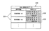
- FIG. 4 is a schematic diagram showing the data structure of the music / vibration correspondence data shown in FIG. 3 in a table format.
- the music / vibration correspondence data 230 includes a plurality of pieces of music information 231 representing different music from each other, and a signal set 232 associated with each of the plurality of pieces of music information 231.
- Each signal set 232 comprises three vibration signals, each representing a vibration in which the stimulus intensity falls within a predetermined stimulus intensity range.
- Each of the three vibration signals represents a vibration corresponding to the music represented by the corresponding music information, and has a different stimulus intensity range.
- Each signal set 232 is composed of an arousal vibration signal, a normal vibration signal, and a relax vibration signal.
- the arousal vibration signal is a vibration signal corresponding to a stimulus intensity range that prompts the user to wake up.
- the normal vibration signal is a vibration signal corresponding to a normal stimulus intensity range that gives a moderate stimulus.
- the relaxation vibration signal is a vibration signal corresponding to a stimulus intensity range in which a weak stimulus for relaxing is provided.
- the music information M1 is associated with a signal set 232 including an arousal vibration signal S11, a normal vibration signal S12, and a relax vibration signal S13.
- the music information M2 is associated with a signal set 232 including an arousal vibration signal S21, a normal vibration signal S22, and a relax vibration signal S23.
- the music / vibration association data 230 enables the vibration device 120 to be controlled by the vibration signal associated with the music information 231 representing the music being reproduced on the car stereo 130 among the plurality of music information 231. It is configured.
- the frequency of the awake vibration signal, the normal vibration signal, and the relaxation vibration signal that constitute each signal set 232 is adjusted so that the frequency of the vibration represented by each vibration signal falls within a predetermined frequency range.
- a frequency range of 20 Hz to 200 Hz is set as an example of a frequency range suitable for providing an awakening effect and / or a relaxing effect.
- the awakening vibration signal, the normal vibration signal, and the relaxing vibration signal are all tempo of the music represented by the music information 231 associated with the signals, the frequency of the sound constituting the chord included in the music, and It represents the vibration according to the strength of the sound.
- a frequency range that is a range of the frequency of occurrence of vibration and a vibration amount range that is a range of the amount of vibration are adopted.
- the arousal vibration signal in order to promote arousal, the frequency of occurrence falls within the arousal frequency range corresponding to a higher frequency of occurrence giving a stronger stimulus, and the awakening vibration amount range corresponding to a larger amount of vibration providing a stronger stimulus.
- the normal vibration signal has an occurrence frequency falling within a normal frequency range corresponding to a normal occurrence frequency giving a moderate stimulus, and a vibration amount falling within a normal vibration amount range corresponding to a normal vibration amount giving a medium stimulus.
- the frequency of the relaxation vibration signal falls within a relaxation frequency range corresponding to a small frequency of occurrence of applying a weak stimulus for relaxing, and a relaxation vibration amount range corresponding to a small amount of vibration of providing a weak stimulus. Represents the vibration in which the amount of vibration falls.
- the storage unit 210 that stores the music / vibration correspondence data 230 having such a data structure is mounted on a moving body, and is a storage medium of a computer on which the vibration control device 220 is constructed, or an externally installed computer.
- the storage unit 210 is not limited to one mounted on a mobile object and fixedly installed, but may be a known portable storage medium, a storage medium installed in a server connected to the computer via a network, or a storage medium. It may be a device.
- the vibration control device 220 shown in FIG. 3 acquires a vibration signal from the storage unit 210 and controls the vibration device 120 installed on the back plate 141 of the seat 140 using the vibration signal. is there.
- the vibration control device 220 includes a vibration signal acquisition unit 221 and an adjustment unit 222 in addition to the output unit 112, the operation input unit 113, and the biological information acquisition unit 115 similar to those in the first embodiment.
- the vibration signal acquisition unit 221 transmits, from the storage unit 210, the vibration signal of the signal set 232 corresponding to the music information 231 acquired by the music information acquisition unit 133 and representing the music being reproduced by the car stereo 130. get.
- the signal set 232 of the signal set 232 is determined according to whether the biological state of the user represented by the biological information acquired by the biological information acquiring unit 115 is a sleepy state, an awake state, or an excited state.
- One vibration signal is acquired from the inside. That is, when the living body state of the user is a sleepy state, an awakening vibration signal is obtained, when the user is in the awake state, a normal vibration signal is obtained, and when the user is in an excited state, a relaxing vibration signal is obtained.
- the adjustment unit 222 When receiving an adjustment operation from the user via the operation input unit 113, the adjustment unit 222 converts the vibration signal acquired by the vibration signal acquisition unit 221 into the frequency of occurrence of the vibration stimulus and the vibration amount. Adjust for points.
- the adjustment unit 222 includes a frequency adjustment unit 222a and a vibration amount adjustment unit 222b.
- the frequency adjustment unit 222a increases or decreases the frequency of occurrence of the vibration signal obtained by the vibration signal obtaining unit 221 by appropriately thinning out or adding the vibration generation timing according to the operation amount of the operation input unit 113. Adjust as follows.
- the vibration amount adjustment unit 222b adjusts the acquired vibration signal so that the vibration amount is appropriately increased or decreased according to the operation amount of the operation input unit 113.
- the adjustment unit 222 sends the vibration signal adjusted in this way to the output unit 112.
- the adjustment unit 222 sends the vibration signal acquired by the vibration signal acquisition unit 221 to the output unit 112 as it is.
- the “output unit” 112 outputs the vibration signal sent from the adjustment unit 222 to the vibration device 120 to cause the vibration device 120 to generate vibration.
- FIG. 5 is a flowchart showing the flow of processing of the vibration control method executed by the vibration control device shown in FIG.
- the adjustment unit 222 determines whether or not the power of the vibration device 120 has been turned on / off with respect to the operation input unit 113 after the start of music playback (step S201). In particular, when the operation is not performed or the ON operation is performed (ON determination in step S201), the output unit 112 is turned ON if the power of the vibration device 120 is OFF at this time (step S202). ). In step S202, if the power of the vibration device 120 is in the ON state at this point, the process proceeds to the next step S204 without performing any particular process.
- step S201 when the off operation is performed (off determination in step S201), if the power of the vibration device 120 is on at this time, the output unit 112 is turned off (step S203), and the process returns to step S201.
- step S203 if the power of the vibration device 120 is off at this point, the process returns to step S201 without performing any process.
- step S204 the vibration signal acquisition unit 221 acquires music information for one measure of the music being reproduced from the music information acquisition unit 133 of the car stereo 130.
- the biological information acquisition unit 115 acquires biological information indicating whether the biological state of the user is a sleepy state, a normal awake state, or an excited state (step S205).
- the vibration signal acquisition unit 221 determines whether the biological state represented by the obtained biological information is a sleepy state, an awake state, or an excited state (step S206).
- the vibration signal acquisition unit 221 reads and acquires one wakeful vibration signal corresponding to the music information being reproduced from the storage unit 210 (step S207). ).
- the vibration signal acquiring unit 221 reads and acquires one measure of the normal vibration signal corresponding to the music information being reproduced from the storage unit 210 (step S208). ).
- the vibration signal acquiring unit 221 reads and acquires one measure of the relaxing vibration signal corresponding to the music information being reproduced from the storage unit 210 (step S209). ).
- the adjustment unit 222 determines whether or not the operation input unit 113 has been subjected to the operation of adjusting the stimulus intensity after the start of the music reproduction (step S210).
- the frequency tuning unit 222a of the adjustment unit 222 adjusts the frequency of occurrence of vibration of the acquired vibration signal according to the operation amount (Step S211). In addition, the frequency tonality unit 222a increases or decreases the vibration amount of the vibration with respect to the acquired vibration signal according to the operation amount (Step S212).
- Step S213 The output unit 112 outputs the vibration signal adjusted or not adjusted by the adjustment unit 222 to the vibration device 120 (Step S213). Thereafter, the process returns to step S201, and the subsequent processes are repeated.
- a vibration control program for causing a computer to execute the vibration control method represented by the flowchart in FIG. 5 is stored in a storage medium of some computer mounted on the moving body.
- the storage medium for storing the vibration control program is not limited to a storage medium of any computer mounted on the moving body, but is installed in a known portable storage medium or a server connected to the computer via a network. Storage medium may be used.
- the storage medium or the storage device as the storage unit 210, and the vibration control device 220 that performs control using the music / vibration correspondence data 230 in the second embodiment described above According to the data structure of the music / vibration correspondence data 230, the storage medium or the storage device as the storage unit 210, and the vibration control device 220 that performs control using the music / vibration correspondence data 230 in the second embodiment described above, The following effects can be obtained.
- the present embodiment it is possible to obtain a vibration signal representing a vibration in which the stimulus intensity falls within a predetermined stimulus intensity range while controlling the vibration device 120 according to the music being reproduced. Therefore, the stimulus intensity range is set to a desired range in which a desired awakening effect and / or a relaxing effect can be obtained, and such an effect can be obtained irrespective of the content of the music being reproduced. Vibration can be generated in the vibration device 120. As described above, according to the present embodiment, it is possible to generate a vibration that can obtain a desired awakening effect and / or a relaxing effect irrespective of the content, while responding to the music being reproduced.
- the vibration device 120 and the vibration control device 220 mounted on the moving body are also exemplified, but the installation place of the vibration device 120 and the vibration control device 220 is not limited to the moving body.
- the vibration device 120 and the vibration control device 220 may be installed on a seat placed in a movie theater or a general residence, for example, as long as they can provide stimulation to the user by vibration. Can be set to
- the installation position of the vibration device 120 is not limited to the position inside the back plate 141 of the seat 140 as in the present embodiment, but may be any position that can provide stimulation to the user. Can be set to
- a signal set 232 including three vibration signals having different stimulus intensity ranges is associated with each of the plurality of music information 231.
- the present embodiment it is possible to perform an operation of selecting a vibration signal in a stimulus intensity range suitable for awakening, relaxation, etc., from the signal set 232 associated with the music being reproduced. Thereby, it is possible to generate a vibration that provides a desired awakening effect and / or a relaxing effect.
- the vibration signal is a signal representing a vibration whose vibration frequency falls within a frequency range of 20 Hz to 200 Hz.
- a frequency range of 20 Hz to 200 Hz is an example of a frequency range suitable for providing an awakening effect and / or a relaxing effect.
- the vibration frequency of the vibration represented by the vibration signal acquired by the vibration signal acquisition unit 221 is suppressed to such a frequency range, and the vibration that appropriately provides the awakening effect and / or the relaxing effect is generated. Can be done.
- the frequency range in which the frequency of the vibration is contained is not limited to the range of 20 Hz to 200 Hz, but may be appropriately set as long as the frequency range is suitable for providing the arousal effect and / or the relaxing effect. obtain.
- the vibration signal is a signal representing vibration according to the tempo of music, the frequency of the sound constituting the chord included in the music, and the strength of the sound.
- the vibration of the vibration signal acquired by the vibration signal acquisition unit 221 is in accordance with the tempo of the music being reproduced or the frequency of the sound that makes up the chord. It is difficult for the vibrations to impair the music being played. As described above, according to the present embodiment, it is possible to generate the vibration for obtaining the awakening effect and / or the relaxing effect without impairing the taste of the music being reproduced.
- the vibration represented by the vibration signal is a vibration corresponding to at least one of the tempo and the frequency of the sound constituting the chord
- the vibration represents only the tempo or only the frequency of the sound constituting the chord. It may be based on.
- an element of vibration determined by an element other than the tempo and an element of vibration determined by an element other than the frequency of the sound constituting the chord are set according to some setting rules.
- the vibration signal is a vibration corresponding to the music tempo
- the frequency of occurrence of the vibration is a signal representing a vibration falling within a predetermined frequency range as the stimulus intensity range.
- the frequency of occurrence of the vibration determined according to the tempo of the music being played back can be adopted as an index indicating the intensity of the stimulus given by the vibration.
- the occurrence frequency is adopted as such an index, and the stimulus intensity range is specifically set as the frequency range. It can be generated effectively.
- the vibration signal is a signal representing a vibration corresponding to the frequency of the sound constituting the music chord.
- the vibration for obtaining the awakening effect and / or the relaxing effect is generated without impairing the taste of the music being reproduced. Can be done.
- the vibration signal is a signal representing a vibration whose vibration amount falls within a predetermined vibration amount range as a stimulus intensity range.
- the amount of vibration can be adopted as an index indicating the intensity of the stimulus given by the vibration.
- the vibration amount is employed as such an index, and the stimulus intensity range is specifically set as the vibration amount range. It can be generated effectively.
- FIG. 6 is a schematic block diagram showing a vibration control device according to a third embodiment, which is mounted on a moving body.
- the same components as those in the first embodiment shown in FIG. 1 are denoted by the same reference numerals as those in FIG. 1, and the description of the same components will be repeated below. Is omitted.
- the moving object is a passenger car, and the same vibration device 120 and car stereo 130 as those in the first embodiment are mounted, and a vibration control device 310 and a storage unit 320 are mounted.
- the vibration control device 310 of the present embodiment includes a vibration signal acquisition unit 111, an output unit 112, an operation input unit 113, a first setting unit 114, a detection unit 117, and a generation unit 118 similar to those of the first embodiment. .
- the vibration control device 310 includes a position information obtaining unit 311 and a second setting unit 312 as components that replace the biological information obtaining unit 115 and the second setting unit 116 in the first embodiment.
- the position information acquisition unit 311 acquires the position of the mobile unit 1 using a positioning system such as GNSS (Global Navigation Satellite System). Further, in the present embodiment, the position information acquiring unit 311 specifies an attribute of a road on which the moving object is located, for example, a general road section or an expressway section, based on the position, and indicates a position indicating the attribute of the road. Generate and obtain information.
- GNSS Global Navigation Satellite System
- the second setting unit 312 sets a frequency range and a vibration amount range in which the occurrence frequency and the vibration amount as the intensity of the vibration stimulus are contained. In this embodiment, the second setting unit 312 compares the setting of these ranges with the position represented by the position information acquired by the position information acquiring unit 311 against the map data 330 stored in the storage unit 320. Do with.
- the second setting unit 312 includes a frequency range setting unit 312a for setting a frequency range and a vibration range setting unit 312b for setting a vibration range.
- FIG. 7 is a schematic diagram showing the data structure of the map data shown in FIG. 6 in a table format.
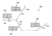
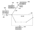
- FIG. 8 is a schematic diagram showing the data structure shown in the table format in FIG. 7 in the map format.
- the map data 330 includes a plurality of link information 331 each representing a road section, and an information set 332 associated with each of the plurality of link information 331. ing.
- Each information set 332 is composed of four pieces of information on the intensity of the stimulus. Each of these four pieces of information is information indicating a stimulus intensity range that contains the intensity of the vibration stimulus.
- the stimulus intensity range a frequency range that is a range of the frequency of occurrence of vibration and a vibration amount range that is a range of the amount of vibration are adopted. Further, in the present embodiment, the frequency range and the vibration amount range are set for each of two time periods, that is, daytime and nighttime. For the daytime when it is difficult for the user of the mobile body to feel drowsy, a frequency range corresponding to a normal occurrence frequency giving a moderate stimulus and a vibration amount range corresponding to a normal vibration amount are set.
- a frequency range corresponding to a large frequency of occurrence providing a strong stimulus and a vibration amount range corresponding to a large vibration amount providing a strong stimulus are provided. Is set.
- link information L11 whose attribute is a general road section and link information L12 whose attribute is a highway section are illustrated.
- link information L13 of the start section of the road corresponding to the automatic driving corresponding to the attribute and link information L14 of the end section of the road corresponding to the automatic driving corresponding to the automatic driving are illustrated.
- the link information L11 of the general road section is associated with an information set 332 including information A111 and A112 of frequency ranges for day and night and information B111 and B112 of vibration amount ranges for day and night respectively. ing.
- An information set 332 made up of information A121 and A122 of frequency ranges for daytime and night and information B121 and B122 of vibration amount ranges for daytime and night respectively is associated with the link information L12 of the expressway section. ing.
- the link information L13 of the start section of the road corresponding to the automatic driving includes an information set 332 including information A131 and A132 of frequency ranges for day and night, and information B131 and B132 of vibration amount ranges for day and night. Are associated with each other.
- the link information L14 of the end section of the road corresponding to the automatic driving includes an information set 332 including information A141 and A142 of frequency ranges for day and night and information B141 and B142 of vibration amount ranges for day and night. Are associated with each other.
- all of the information A121,..., B122 corresponding to the link information L12 of the expressway section is based on the information A111,. It also provides information on strong stimuli.
- the information A131,..., And B132 corresponding to the link information L13 of the start section are all information A141,. .., Information on a stimulus weaker than B142.
- the map data 330 is configured so that the stimulus intensity can be set based on the stimulus intensity information of the information set 332 associated with the link information 331 indicating the road section where the moving object is located. Also, since the stimulus intensity information of each information set 332 is set for each of the daytime and nighttime time zones, the stimulus intensity can be set for each time zone.
- the storage unit 320 that stores the map data 330 having such a data structure is mounted on a moving body and is a storage medium of a computer on which the vibration control device 310 is constructed, or a storage externally provided to the computer. It is stored in the device.
- the storage unit 320 is not limited to one mounted on a moving body and fixedly installed, but may be a known portable storage medium, a storage medium installed in a server connected to this computer via a network, or a storage medium. It may be a device.
- a server connected to the vibration control device 310 via the network acquires position information, time information, and a biological state of the user from the plurality of mobiles,
- the easiness of sleepiness may be specified for each road section by statistical processing, and stimulus intensity information corresponding to each road section may be set for each time zone.
- Statistical processing performed by the server may be executed based on information acquired from an unspecified number of moving objects, or may be individually executed for each moving object based on information acquired from each moving object. .
- the map data 330 generated in this manner may be distributed to each mobile unit and stored in the storage unit 320 of the vibration control device 310.
- the vibration control device 310 shown in FIG. 6 acquires the stimulus intensity information from the storage unit 320 and controls the vibration device 120 installed on the back plate 141 of the seat 140 using the information. is there.
- the position information obtaining unit 311 obtains, as position information indicating the position of the moving object, information indicating the attribute of the road on which the moving object is located. Then, the frequency range setting unit 312a of the second setting unit 312 corresponds to the link information 331 indicating the road section having the attribute indicated by the acquired position information and the information of the frequency range corresponding to the time zone at that time. Is obtained from the storage unit 320 and a frequency range is set. Similarly, the vibration amount range setting unit 312b stores the information of the vibration amount range corresponding to the link information 331 indicating the road section of the attribute indicated by the acquired position information and corresponding to the time zone at that time. And set the vibration amount range.
- the generation unit 118 vibrates based on the tempo of the music being reproduced detected by the detection unit 117, the frequency of the sound constituting the chord, the strength of the sound, the frequency range and the vibration amount range set by the second setting unit 312. Is generated.
- the vibration represented by the vibration signal generated in this manner corresponds to the music being reproduced, and the frequency of occurrence and the amount of vibration fall within the frequency range and the vibration amount range set by the second setting unit 312, respectively.
- the vibration signal generated by the generation unit 118 is obtained by the vibration signal obtaining unit 111, and the output unit 112 outputs the vibration signal to the vibration device 120 to cause the vibration device 120 to generate vibration.
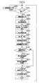
- FIG. 9 is a flowchart showing the flow of processing of the vibration control method executed by the vibration control device shown in FIG.
- the process represented by this flowchart starts when music is started to be reproduced on the car stereo 130 and music information is sent to the vibration control device 310.
- the generation unit 118 determines whether or not the power of the vibration device 120 has been turned on / off with respect to the operation input unit 113 after the start of music reproduction (step S301). In particular, when the operation is not performed or the ON operation is performed (ON determination in step S301), the output unit 112 is turned ON if the power of the vibration device 120 is OFF at this time (step S302). ). In step S302, if the power of the vibration device 120 is on at this time, the process proceeds to the next step S304 without performing any particular process.
- step S301 when the off operation is performed (off determination in step S301), if the power of the vibration device 120 is on at this time, the output unit 112 is turned off (step S303), and the process returns to step S301.
- step S303 if the power of the vibration device 120 is off at this point, the process returns to step S301 without performing any particular process.
- step S304 the detection unit 117 acquires music information for one measure of the music being reproduced from the music information output unit 131 of the car stereo 130. Subsequently, the detecting unit 117 detects the tempo, the frequency of the sound constituting the chord, and the strength of the sound based on the acquired music information (step S305).
- the position information acquiring unit 311 acquires position information indicating the attribute of the road on which the moving object is located (step S306). Further, the second setting unit 312 uses a timer (not shown) to determine whether the time zone at this time is day or night (step S307).
- the frequency range setting unit 312a stores the information of the frequency range corresponding to the link information 331 indicating the road section having the attribute indicated by the position information and corresponding to any of the determined day and night time zones.
- the frequency range is set by acquiring the frequency range.
- the vibration amount range setting unit 312b stores the information of the vibration amount range corresponding to the link information 331 indicating the road section having the attribute indicated by the position information and corresponding to the determined time zone. And set the vibration amount range.
- the generation unit 118 determines whether or not the operation input unit 113 has been subjected to the stimulus intensity adjustment operation after the start of music reproduction. (Step S310).
- Step S310 If there is an adjustment operation (Yes in Step S310), the frequency range setting unit 114a of the first setting unit 114 increases or decreases the set frequency range according to the operation amount (Step S311). Also, the vibration amount surrounding setting unit 114b increases or decreases the set vibration amount range according to the operation amount (step S312).
- steps S311 and S312 are omitted, and the process proceeds to the next step S313.
- step S313 based on the tempo, the frequency of the sound constituting the chord, the strength of the sound, the frequency range, and the vibration amount range obtained in the processing up to this point, the generation unit 118 converts the music information for one measure into Generate a corresponding vibration signal. That is, the frequency of occurrence falls within the frequency range according to the tempo of the measure, the frequency falls within the frequency range of 20 Hz to 200 Hz according to the chord of the measure, and the amount of vibration is the intensity of the sound of the measure. , A vibration signal representing a vibration falling within the vibration amount range is generated.
- the vibration signal acquisition unit 111 acquires the vibration signal for one bar generated in this way (step S314), and the output unit 112 outputs the vibration signal to the vibration device 120 (step S315). Thereafter, the process returns to step S301, and the subsequent processes are repeated.
- a vibration control program for causing a computer to execute the vibration control method represented by the flowchart in FIG. 9 is stored in a storage medium of some computer mounted on the moving body.
- the storage medium for storing the vibration control program is not limited to a storage medium of any computer mounted on the moving body, but is installed in a known portable storage medium or a server connected to the computer via a network. Storage medium may be used.
- the vibration control device 310 According to the vibration control device 310, the vibration control method, the vibration control program, and the storage medium of the third embodiment described above, the following effects can be obtained.
- the road on which the moving object moves may be relaxed by releasing the tension to some extent, such as a highway, a road where the user driving the moving object easily sleeps, or a self-driving road.
- a vibration signal representing a vibration corresponding to the position information representing the position of the moving body while acquiring the music being reproduced is acquired and output to the vibration device 120.
- This makes it possible to generate a vibration that can provide a desired awakening effect and / or a relaxing effect irrespective of the content, while responding to the music being reproduced.
- the installation position of the vibration device 120 on the moving body is not limited to the position inside the back plate 141 of the seat 140, but may be set arbitrarily as long as it can provide a stimulus to the user.
- the position information obtaining unit 311 obtains, as position information, attributes of a road on which the moving object is located, such as a general road section and an expressway section.
- the attribute of a road such as a highway or an autonomous driving road, that affects the biological condition of the user is acquired as position information. Then, by generating vibration according to such position information, it is possible to effectively obtain an awakening effect and / or a relaxing effect.
- the position information acquired by the position information acquisition unit 311 is not limited to the information indicating the attribute of the road as described above, and may be, for example, information indicating the position of the moving object itself obtained by GNSS. .
- the vibration control device 310 includes the second setting unit 312 that sets the stimulus intensity range that includes the stimulus intensity based on the position information acquired by the position information acquisition unit 311. Then, the vibration signal acquisition unit 111 acquires, as a vibration signal, a signal indicating a vibration in which the stimulus intensity falls within the stimulus intensity range set by the second setting unit 312.
- an appropriate stimulus according to the position of the moving object is given to the user, so that the desired awakening effect and / or relaxing effect are appropriate. Can be generated.
- the vibration signal acquiring unit 111 acquires a signal representing a vibration whose vibration frequency falls within a frequency range of 20 Hz to 200 Hz as a vibration signal.
- a frequency range of 20 Hz to 200 Hz is an example of a frequency range suitable for providing an awakening effect and / or a relaxing effect.
- the vibration frequency of the vibration represented by the vibration signal acquired by the vibration signal acquisition unit is suppressed to such a frequency range, and the vibration that appropriately provides the awakening effect and / or the relaxing effect is generated. be able to.
- the frequency range for containing the frequency of the vibration is not limited to the range of 20 Hz to 200 Hz, and may be appropriately set as long as it is a frequency range suitable for producing the arousal effect and / or the relaxing effect.
- the vibration signal acquisition unit 111 acquires a signal representing a vibration corresponding to the tempo of the music, the frequency of the sound constituting the chord included in the music, and the strength of the sound as the vibration signal. I do.
- the vibration of the vibration signal acquired by the vibration signal acquisition unit 111 is in accordance with the tempo of the music being played or the frequency of the sound that makes up the chord, so that the vibration signal It is difficult for the vibrations to impair the music being played.
- the vibration represented by the vibration signal may be based on only the tempo or only the frequency of the sound constituting the chord, as long as the vibration corresponds to at least one of the tempo and the frequency of the sound constituting the chord.
- the vibration element determined by an element other than the tempo and the vibration element determined by the frequency of the sound constituting the chord are set according to some setting rules.
- the present embodiment includes the frequency range setting unit 312 a that sets the frequency range in which the frequency of occurrence of the vibration represented by the vibration signal is contained based on the position information acquired by the position information acquiring unit 311. Then, the vibration signal acquiring unit 111 acquires, as a vibration signal, a signal representing a vibration corresponding to the music tempo, the frequency of occurrence of which falls within the frequency range set by the frequency range setting unit 312a.
- the frequency of occurrence of the vibration determined according to the tempo of the music being played back can be adopted as an index indicating the intensity of the stimulus given by the vibration.
- the frequency of occurrence is adopted as such an index, and the stimulus intensity range is specifically set as the frequency range. Can be generated.
- the vibration signal acquiring unit 111 acquires a signal representing a vibration corresponding to a frequency of a sound constituting a music code as a vibration signal.
- the vibration for obtaining the awakening effect and / or the relaxing effect is generated without impairing the taste of the music being reproduced. Can be done.
- the vibration control device 310 of the present embodiment includes a vibration amount range setting unit 312b that sets a vibration amount range that includes the vibration amount of the vibration represented by the vibration signal based on the position information acquired by the position information acquisition unit 311. Have. Then, the vibration signal acquisition unit 111 acquires a signal representing a vibration whose vibration amount falls within the vibration amount range set by the vibration amount range setting unit 312b as a vibration signal.
- the amount of vibration can be adopted as an index indicating the intensity of the stimulus given by the vibration.
- the vibration amount is employed as such an index, and the stimulus intensity range is specifically set as the vibration amount range. It can be generated effectively.
- the stimulus intensity ranges two types, i.e., a frequency range and a vibration amount range, are set as the stimulus intensity ranges.
- the stimulus intensity range mentioned here may be only one of the frequency range and the vibration amount range, or use any index indicating the intensity of the vibration stimulus other than the occurrence frequency and the vibration amount. May be within the range.
- the vibration control includes both the first setting unit 114 that sets the stimulus intensity range in response to the operation of the user and the second setting unit 312 that sets the stimulus intensity range based on the position information.
- Apparatus 310 is illustrated.
- the vibration control device is not limited to this, and may include only one of the above-described second setting units 312 and the like.
- the vibration control device 310 includes a detection unit 117 and a generation unit 118.
- the detection unit 117 detects, as music elements, a music tempo, a frequency of a sound included in a chord included in the music, and a strength of the sound.
- the generation unit 118 generates a vibration signal based on the music element detected by the detection unit 117. Then, the vibration signal acquisition unit 111 acquires the vibration signal generated by the generation unit 118.
- vibration for obtaining an awakening effect and / or a relaxing effect is further added to the taste of the music being reproduced. It can be generated without loss.
- the stimulus intensity information associated with the link information 331 indicating the road section where the moving object is located is obtained, and the stimulus intensity is set based on the information. Vibration can be generated in the vibration device 120. For this reason, it is possible to perform an operation such as setting the intensity of the stimulus given by the vibration to an intensity suitable for the awakening effect and / or the relaxing effect according to the position of the moving object. This makes it possible to generate a vibration that can provide a desired awakening effect and / or a relaxing effect irrespective of the content, while responding to the music being reproduced.
- the stimulus intensity information associated with the link information L12 indicating the highway section is information on stronger stimulus than the stimulus intensity information associated with the link information L11 indicating the general road section. Has become.
- an appropriate awakening effect can be obtained by giving a strong stimulus to the user in a highway section where the user tends to drowsy as compared to a general road section.
- the stimulus intensity information associated with the link information L13 indicating the start section of the automatic driving corresponding road is based on the stimulus intensity information associated with the link information L14 indicating the end section of the automatic driving corresponding road. Also provides information on weak stimuli.
- an appropriate relaxation effect can be obtained by relaxing the stimulus given to the user in the start section of the self-driving road where relaxation is allowed, as compared with the end section.
- a plurality of pieces of stimulus intensity information are associated with each of the plurality of link information 331 as information relating to the stimulus intensity for each of day and night time zones.
- the data structure of the map data 330 according to the present embodiment is configured so that the stimulus intensity can be set for each time zone by a plurality of stimulus intensity information items associated with the link information 331 indicating the road section where the moving object is located. ing.
- the biological state of the user is in a state according to the time zone such that the user is more likely to fall asleep at night than during the day.
- the intensity of the stimulus can be set for each time period, a vibration that provides an appropriate awakening effect and / or a relaxing effect according to the user's biological state for each time period is generated. be able to.
- the information on the frequency range and the information on the vibration amount range as the information on the intensity of the stimulus are respectively set twice each day and night.
- the setting of the information for each time zone here is not limited to the setting of the two divisions of day and night, and may be set for each of the more divided plural time zones.
- the stimulus intensity information is information indicating a stimulus intensity range that includes the stimulus intensity.
- the use of the information indicating the stimulus intensity range is preferable because the stimulus intensity that changes momentarily according to the music being reproduced can be comprehensively set.
- the stimulus intensity ranges two types, i.e., a frequency range and a vibration amount range, are set as the stimulus intensity ranges.
- the stimulus intensity range mentioned here may be only one of the frequency range and the vibration amount range, or use any index indicating the intensity of the vibration stimulus other than the occurrence frequency and the vibration amount. May be within the range.
- link information 331 link information L11 of a general road section, link information L12 of a highway section, link information L13 of a start section of an automatic driving corresponding road, and an end section of an automatic driving corresponding road.
- Link information L14 is illustrated.
- the link information 331 is not limited to such information, and may be, for example, information indicating a range from the start point to the end point of the road section specified by the GNSS.
- FIG. 10 is a schematic diagram showing, in the form of a table, a data structure of a modification of the data structure of the map data shown in FIGS. 7 and 8.
- FIG. 11 is a schematic diagram showing the data structure shown in the table format in FIG. 10 in the map format.
- the map data 430 having the data structure shown in FIGS. 10 and 11 includes a plurality of map element information 431 each representing an element on a map, and an information set associated with each of the plurality of map element information 431. 432.
- Each information set 432 is made up of four pieces of information on the intensity of the stimulus.
- the four pieces of information are information indicating the frequency range and the vibration amount range for each of two time periods, day and night, similarly to the four pieces of information included in the information set 332 illustrated in FIGS. 7 and 8. I have.
- FIGS. 10 and 11 illustrate, as an example of the map element information 431, information indicating a first road link L21 corresponding to a general road and information indicating a second road link L22 corresponding to an expressway section. Further, information indicating a first node N23 corresponding to a branch point in a highway section and information indicating a first area Ar24 including an autonomous driving support road are illustrated.
- the information representing the second road link L22 of the expressway section includes a frequency range corresponding to a stimulus stronger than the frequency range and the vibration amount range of the information set 432 corresponding to the information representing the first road link L21 of the general road.
- the information set 432 of the vibration amount range is associated.
- the information representing the first node N23 of the branch point includes a frequency range corresponding to a stimulus stronger than the frequency range and the vibration amount range of the information set 432 corresponding to the information representing the second road link L22 of the expressway section. And an information set 432 of the vibration range.
- the information representing the first area Ar24 of the road for automatic driving includes, in the information set 432 corresponding to the information representing the first road link L21 of the general road, the frequency corresponding to the stimulus weaker than the frequency range or the vibration amount range of the information set 432.
- the information set 432 of the range and the vibration amount range is associated.
- the information of the first road link L21 of the general road section includes information A211 and A212 of frequency ranges for day and night, and information B211, and information B21 of vibration amount ranges for day and night.
- B212 is associated with the information set 432.
- the information of the second road link L22 of the expressway section includes an information set 432 including information A221 and A222 of frequency ranges for day and night and information B221 and B222 of vibration amount ranges for day and night respectively. Are associated with each other.
- the information of the first node N23 at the branch point corresponds to an information set 432 including information A231 and A232 for frequency ranges for day and night and information B231 and B232 for vibration amount ranges for day and night respectively. It is attached.
- the information representing the first area Ar24 of the road for automatic driving includes an information set including information A241 and A242 for frequency ranges for day and night and information B241 and B242 for vibration amount ranges for day and night respectively. 432 are associated with each other.
- the map data 430 having the data structure of the modified example described above is also configured so that the stimulus intensity can be set by the stimulus intensity information of the information set 432 associated with the map element information 431 corresponding to the position of the moving object. .
- the stimulus intensity information of each information set 432 is set for each of the daytime and nighttime time zones, the stimulus intensity can be set for each time zone.
- the map data 430 having such a data structure is stored in a storage medium of a computer in which the vibration control device 310 is built by being mounted on a moving body, or similar to the map data 330 shown in FIG. On the other hand, it is stored in an externally installed storage device.
- the storage unit is not limited to the one mounted on the moving body and fixedly installed, but may be a known portable storage medium, a storage medium or a storage device installed in a server connected to the computer via a network. It may be.
- a server connected to the vibration control device 310 via a network acquires position information, time information, and a biological state of the user from the plurality of mobiles,
- the ease of sleepiness may be specified for each map element by statistical processing, and stimulus intensity information corresponding to each map element may be set for each time zone.
- Statistical processing performed by the server may be executed based on information acquired from an unspecified number of moving objects, or may be individually executed for each moving object based on information acquired from each moving object. .
- the map data 430 generated in this manner may be distributed to each mobile unit and stored in the storage unit 320 of the vibration control device 310.
- the data structure of the map data 430 of this modification information on the frequency range and the vibration amount range associated with the map element information 431 indicating the element to which the position of the moving object belongs is obtained, and the information is generated based on the information. Vibration in which the frequency and the vibration amount are set can be generated in the vibration device 120. For this reason, it is possible to perform an operation such as setting the intensity of the stimulus given by the vibration to an intensity suitable for the awakening effect and / or the relaxing effect according to the position of the moving object. This makes it possible to generate a vibration that can provide a desired awakening effect and / or a relaxing effect irrespective of the content, while responding to the music being reproduced.
- the information on the frequency range and the information on the vibration amount range as the information on the intensity of the stimulus are respectively set twice each day and night.
- the setting of the information for each time zone here is not limited to the setting of two divisions of day and night, and may be set for each of more subdivided plural time zones.
- the stimulus intensity range here may be only one of the frequency range and the vibration amount range, or some index indicating the intensity of the vibration stimulus other than the frequency of occurrence and the vibration amount is used. May be within the range.
- the present invention is not limited to the above-described embodiments and modified examples, but includes other configurations that can achieve the object of the present invention, and the following modified examples are also included in the present invention. .
- the vibration control devices 110, 220, and 310 on which the moving body as the passenger car is mounted are exemplified.
- the moving body on which the vibration control device is mounted is not limited to a passenger car, but may be a motorcycle, a large vehicle such as a truck or a bus, or the like, and does not matter the specific type of the moving body.
- the vibration signal acquisition unit 111 that acquires the vibration signal internally generated by the generation unit 118 of the vibration control devices 110 and 310 mounted on the moving body is exemplified. ing.
- the vibration signal acquisition unit 221 that reads and acquires a vibration signal from the storage unit 210 mounted on the moving body is illustrated.
- the vibration signal acquisition unit is not limited to these, and may acquire, for example, a vibration signal generated on a server outside the moving object via a wireless network. Alternatively, the vibration signal may be read out from a storage unit constructed on the server via a wireless network and acquired.
Landscapes
- Health & Medical Sciences (AREA)
- Anesthesiology (AREA)
- Life Sciences & Earth Sciences (AREA)
- Animal Behavior & Ethology (AREA)
- Acoustics & Sound (AREA)
- Psychology (AREA)
- Engineering & Computer Science (AREA)
- Biomedical Technology (AREA)
- Heart & Thoracic Surgery (AREA)
- Hematology (AREA)
- Veterinary Medicine (AREA)
- Physics & Mathematics (AREA)
- General Health & Medical Sciences (AREA)
- Public Health (AREA)
- Pain & Pain Management (AREA)
- Details Of Audible-Bandwidth Transducers (AREA)
- Circuit For Audible Band Transducer (AREA)
- Traffic Control Systems (AREA)
- Chair Legs, Seat Parts, And Backrests (AREA)
- Percussion Or Vibration Massage (AREA)
Abstract
Description
111,221 振動信号取得部
112 出力部
113 操作入力部
114 第1設定部
114a,116a,312a 頻度範囲設定部
114b,116b,312b 振動量範囲設定部
115 生体情報取得部
116,312 第2設定部
117 検出部
118 生成部
120 振動装置
130 カーステレオ
131 音楽情報出力部
132 車両スピーカ
133 音楽情報取得部
140 シート
141 背部板
210,320 記憶部
222 調整部
222a 頻度調整部
222b 振動量調整部
230 音楽/振動対応データ
231,M1,M2 音楽情報
232 信号セット
311 位置情報取得部
330 地図データ
331,L11,L12,L13,L14 リンク情報
332,432 情報セット
431 地図要素情報
A111,A121,A131,A141 昼用の頻度範囲の情報
A112,A122,A132,A142 夜用の頻度範囲の情報
B111,B121,B131,B141 昼用の振動量範囲の情報
B112,B122,B132,B142 夜用の振動量範囲の情報
L21 第1道路リンク
L22 第2道路リンク
N23 第1ノード
Ar24 第1エリア
S11,S21 覚醒振動信号
S12,S22 通常振動信号
S13,S23 リラックス振動信号
Claims (12)
- 再生中の音楽に応じた振動を発生させてユーザに刺激を与える振動装置を制御する振動制御装置であって、
前記刺激の強度が所定の刺激強度範囲に収まる前記振動を表す振動信号を取得する振動信号取得部と、
前記振動信号取得部で取得された前記振動信号を前記振動装置に出力する出力部と、
を備えたことを特徴とする振動制御装置。 - 前記振動信号取得部が、振動周波数が所定周波数範囲に収まる振動を表す信号を、前記振動信号として取得することを特徴とする請求項1に記載の振動制御装置。
- 前記振動信号取得部が、前記音楽のテンポ、及び、前記音楽に含まれるコードを構成する音の周波数、の少なくとも一方に応じた振動を表す信号を、前記振動信号として取得することを特徴とする請求項1又は2に記載の振動制御装置。
- 前記振動信号取得部が、前記音楽のテンポに応じる振動であって、当該振動の発生頻度が前記刺激強度範囲としての所定の頻度範囲に収まる振動を表す信号を、前記振動信号として取得することを特徴とする請求項1~3のうち何れか一項に記載の振動制御装置。
- 前記振動信号取得部が、前記音楽のコードを構成する音の周波数に応じる振動を表す信号を、前記振動信号として取得することを特徴とする請求項1~4のうち何れか一項に記載の振動制御装置。
- 前記振動信号取得部が、前記振動の振動量が、前記刺激強度範囲としての所定の振動量範囲に収まる振動を表す信号を、前記振動信号として取得することを特徴とする請求項1~5のうち何れか一項に記載の振動制御装置。
- 前記ユーザの操作を受けて、前記刺激強度範囲を設定する第1設定部を備え、
前記振動信号取得部は、前記刺激の強度が、前記第1設定部で設定された前記刺激強度範囲に収まる振動を表す信号を、前記振動信号として取得することを特徴とする請求項1~6のうち何れか一項に記載の振動制御装置。 - 前記ユーザの生体状態を表す生体情報を取得する生体情報取得部と、
前記生体情報取得部で取得された前記生体情報に基づいて、前記刺激強度範囲を設定する第2設定部と、を備え、
前記振動信号取得部は、前記刺激の強度が、前記第2設定部で設定された前記刺激強度範囲に収まる振動を表す信号を、前記振動信号として取得することを特徴とする請求項1~6のうち何れか一項に記載の振動制御装置。 - 前記音楽から、前記音楽のテンポ、及び、前記音楽に含まれるコードを構成する音の周波数、の少なくとも一方を音楽要素として検出する検出部と、
前記検出部で検出された前記音楽要素に基づいて前記振動信号を生成する生成部と、を備え、
前記振動信号取得部が、前記生成部で生成された前記振動信号を取得することを特徴とする請求項1~8のうち何れか一項に記載の振動制御装置。 - 再生中の音楽に応じた振動を発生させてユーザに刺激を与える振動装置を制御する振動制御方法であって、
前記刺激の強度が所定の刺激強度範囲に収まる前記振動を表す振動信号を取得する振動信号取得工程と、
前記振動信号取得工程で取得された前記振動信号を前記振動装置に出力する出力工程と、
を備えたことを特徴とする振動制御方法。 - 請求項10に記載された振動制御方法をコンピュータに実行させることを特徴とする振動制御プログラム。
- 請求項11に記載された振動制御プログラムを記憶したことを特徴とする記憶媒体。
Priority Applications (5)
| Application Number | Priority Date | Filing Date | Title |
|---|---|---|---|
| JP2020550283A JPWO2020071136A1 (ja) | 2018-10-03 | 2019-09-19 | 振動制御装置、振動制御方法、振動制御プログラム、及び記憶媒体 |
| EP19869316.0A EP3863300A4 (en) | 2018-10-03 | 2019-09-19 | Vibration control device, vibration control method, vibration control program, and recording medium |
| US17/282,688 US12311115B2 (en) | 2018-10-03 | 2019-09-19 | Vibration control device, vibration control method, vibration control program, and recording medium |
| JP2023037342A JP2023060333A (ja) | 2018-10-03 | 2023-03-10 | 振動制御装置、振動制御方法、振動制御プログラム、及び記憶媒体 |
| JP2024200215A JP2025015710A (ja) | 2018-10-03 | 2024-11-18 | 振動制御装置、振動制御方法、振動制御プログラム、及び記憶媒体 |
Applications Claiming Priority (2)
| Application Number | Priority Date | Filing Date | Title |
|---|---|---|---|
| JP2018188004 | 2018-10-03 | ||
| JP2018-188004 | 2018-10-03 |
Publications (1)
| Publication Number | Publication Date |
|---|---|
| WO2020071136A1 true WO2020071136A1 (ja) | 2020-04-09 |
Family
ID=70055889
Family Applications (1)
| Application Number | Title | Priority Date | Filing Date |
|---|---|---|---|
| PCT/JP2019/036711 Ceased WO2020071136A1 (ja) | 2018-10-03 | 2019-09-19 | 振動制御装置、振動制御方法、振動制御プログラム、及び記憶媒体 |
Country Status (4)
| Country | Link |
|---|---|
| US (1) | US12311115B2 (ja) |
| EP (1) | EP3863300A4 (ja) |
| JP (3) | JPWO2020071136A1 (ja) |
| WO (1) | WO2020071136A1 (ja) |
Cited By (2)
| Publication number | Priority date | Publication date | Assignee | Title |
|---|---|---|---|---|
| CN113173180A (zh) * | 2021-04-20 | 2021-07-27 | 宝能(广州)汽车研究院有限公司 | 应用于驾驶位的振动方法、装置、设备及存储介质 |
| US20230166292A1 (en) * | 2020-04-30 | 2023-06-01 | Pioneer Corporation | Vibration signal generation device |
Families Citing this family (3)
| Publication number | Priority date | Publication date | Assignee | Title |
|---|---|---|---|---|
| US20230181868A1 (en) * | 2021-12-09 | 2023-06-15 | Ford Global Technologies, Llc | Systems and methods to provide a relaxation regimen to an occupant of a vehicle |
| CN114983789B (zh) * | 2022-07-07 | 2023-04-07 | 苏州市立医院 | 一种三维旋进式智能振动理疗仪控制系统 |
| WO2026094189A1 (ja) * | 2024-10-30 | 2026-05-07 | 日本電気株式会社 | 運転支援装置、運転支援方法及び記録媒体 |
Citations (6)
| Publication number | Priority date | Publication date | Assignee | Title |
|---|---|---|---|---|
| JP2004275668A (ja) | 2003-03-14 | 2004-10-07 | Tamagawa Kasei:Kk | 低周波音増幅発振装置およびその使用方法 |
| JP2008000222A (ja) * | 2006-06-20 | 2008-01-10 | Sanei:Kk | 安眠支援システム、安眠支援プログラムおよびその記録媒体 |
| JP2013251750A (ja) * | 2012-05-31 | 2013-12-12 | Sony Computer Entertainment Inc | ヘッドホン |
| JP2014126593A (ja) * | 2012-12-25 | 2014-07-07 | Pioneer Electronic Corp | 支援システム |
| JP2015045879A (ja) * | 2006-04-13 | 2015-03-12 | イマージョン コーポレーションImmersion Corporation | デジタル音声信号からハプティック・イベントを自動生成するシステム及び方法 |
| WO2016027366A1 (ja) * | 2014-08-22 | 2016-02-25 | パイオニア株式会社 | 振動信号生成装置及び振動信号生成方法 |
Family Cites Families (5)
| Publication number | Priority date | Publication date | Assignee | Title |
|---|---|---|---|---|
| JP3341238B2 (ja) * | 1999-09-14 | 2002-11-05 | 株式会社アクーヴ・ラボ | 振動を人体に感じさせる方法及びその装置 |
| CN1248666C (zh) * | 2000-12-08 | 2006-04-05 | 发美利株式会社 | 按摩装置 |
| JP2010266748A (ja) * | 2009-05-15 | 2010-11-25 | Panasonic Electric Works Co Ltd | 音響振動再生装置並びに音響振動再生方法 |
| CN108090595A (zh) * | 2016-11-22 | 2018-05-29 | 松下知识产权经营株式会社 | 压力改善系统及压力改善方法 |
| CN108310586B (zh) * | 2017-12-27 | 2021-04-20 | 厦门乐范健康科技有限公司 | 一种基于音乐节奏的按摩模式控制方法与按摩器 |
-
2019
- 2019-09-19 US US17/282,688 patent/US12311115B2/en active Active
- 2019-09-19 WO PCT/JP2019/036711 patent/WO2020071136A1/ja not_active Ceased
- 2019-09-19 JP JP2020550283A patent/JPWO2020071136A1/ja not_active Ceased
- 2019-09-19 EP EP19869316.0A patent/EP3863300A4/en active Pending
-
2023
- 2023-03-10 JP JP2023037342A patent/JP2023060333A/ja active Pending
-
2024
- 2024-11-18 JP JP2024200215A patent/JP2025015710A/ja active Pending
Patent Citations (6)
| Publication number | Priority date | Publication date | Assignee | Title |
|---|---|---|---|---|
| JP2004275668A (ja) | 2003-03-14 | 2004-10-07 | Tamagawa Kasei:Kk | 低周波音増幅発振装置およびその使用方法 |
| JP2015045879A (ja) * | 2006-04-13 | 2015-03-12 | イマージョン コーポレーションImmersion Corporation | デジタル音声信号からハプティック・イベントを自動生成するシステム及び方法 |
| JP2008000222A (ja) * | 2006-06-20 | 2008-01-10 | Sanei:Kk | 安眠支援システム、安眠支援プログラムおよびその記録媒体 |
| JP2013251750A (ja) * | 2012-05-31 | 2013-12-12 | Sony Computer Entertainment Inc | ヘッドホン |
| JP2014126593A (ja) * | 2012-12-25 | 2014-07-07 | Pioneer Electronic Corp | 支援システム |
| WO2016027366A1 (ja) * | 2014-08-22 | 2016-02-25 | パイオニア株式会社 | 振動信号生成装置及び振動信号生成方法 |
Cited By (3)
| Publication number | Priority date | Publication date | Assignee | Title |
|---|---|---|---|---|
| US20230166292A1 (en) * | 2020-04-30 | 2023-06-01 | Pioneer Corporation | Vibration signal generation device |
| US12070771B2 (en) * | 2020-04-30 | 2024-08-27 | Pioneer Corporation | Vibration signal generation device |
| CN113173180A (zh) * | 2021-04-20 | 2021-07-27 | 宝能(广州)汽车研究院有限公司 | 应用于驾驶位的振动方法、装置、设备及存储介质 |
Also Published As
| Publication number | Publication date |
|---|---|
| JPWO2020071136A1 (ja) | 2021-09-30 |
| US20210379328A1 (en) | 2021-12-09 |
| JP2023060333A (ja) | 2023-04-27 |
| EP3863300A1 (en) | 2021-08-11 |
| US12311115B2 (en) | 2025-05-27 |
| JP2025015710A (ja) | 2025-01-30 |
| EP3863300A4 (en) | 2022-06-29 |
Similar Documents
| Publication | Publication Date | Title |
|---|---|---|
| JP2023060333A (ja) | 振動制御装置、振動制御方法、振動制御プログラム、及び記憶媒体 | |
| JP2020057954A (ja) | 振動制御装置、振動制御方法、振動制御プログラム、及び記憶媒体 | |
| US20170182284A1 (en) | Device and Method for Generating Sound Signal | |
| JP2001086580A (ja) | 振動音楽の表現方法及びその装置 | |
| US20170245070A1 (en) | Vibration signal generation apparatus and vibration signal generation method | |
| US10857323B2 (en) | Audio signal generation device, audio signal generation method, and computer-readable storage medium | |
| JP2020056932A (ja) | データ構造、記憶媒体、記憶装置、及び振動制御装置 | |
| JPWO2019211990A1 (ja) | 振動制御装置 | |
| JP2024153944A (ja) | 振動信号生成装置 | |
| KR101441820B1 (ko) | 주파수 추종 반응을 이용한 감성조절 장치 | |
| JP2020057955A (ja) | 振動制御装置、振動制御方法、振動制御プログラム、及び記憶媒体 | |
| JP2020056933A (ja) | データ構造、記憶媒体、及び記憶装置 | |
| JP2013171546A (ja) | 再生装置、再生方法およびプログラム | |
| JP2019196073A (ja) | 乗物乗員の活性化度合適正化システム | |
| JP2021175146A (ja) | 振動信号出力装置 | |
| US20240009421A1 (en) | Emotional care apparatus and method thereof | |
| JP3103288B2 (ja) | 覚醒維持装置及び覚醒維持用記録媒体 | |
| JP2019193699A (ja) | 振動制御装置 | |
| KR102370514B1 (ko) | 바이노럴 음향 재생 제어 시스템 및 그 방법 | |
| JP2003223174A (ja) | 音発生装置、音発生空間及び音 | |
| US20170229113A1 (en) | Environmental sound generating apparatus, environmental sound generating system using the apparatus, environmental sound generating program, sound environment forming method and storage medium | |
| JPH11109985A (ja) | オーディオ装置及び覚醒維持方法 | |
| JPH09313610A (ja) | 音発生装置、音発生空間及び音 | |
| JP3129623B2 (ja) | 覚醒維持装置 | |
| JPH10309958A (ja) | 覚醒装置 |
Legal Events
| Date | Code | Title | Description |
|---|---|---|---|
| 121 | Ep: the epo has been informed by wipo that ep was designated in this application |
Ref document number: 19869316 Country of ref document: EP Kind code of ref document: A1 |
|
| ENP | Entry into the national phase |
Ref document number: 2020550283 Country of ref document: JP Kind code of ref document: A |
|
| NENP | Non-entry into the national phase |
Ref country code: DE |
|
| ENP | Entry into the national phase |
Ref document number: 2019869316 Country of ref document: EP Effective date: 20210503 |
|
| WWG | Wipo information: grant in national office |
Ref document number: 17282688 Country of ref document: US |