WO2020071238A1 - Mécanisme de pompe à vide fixé d'un seul tenant à un matériau d'emballage - Google Patents
Mécanisme de pompe à vide fixé d'un seul tenant à un matériau d'emballageInfo
- Publication number
- WO2020071238A1 WO2020071238A1 PCT/JP2019/037890 JP2019037890W WO2020071238A1 WO 2020071238 A1 WO2020071238 A1 WO 2020071238A1 JP 2019037890 W JP2019037890 W JP 2019037890W WO 2020071238 A1 WO2020071238 A1 WO 2020071238A1
- Authority
- WO
- WIPO (PCT)
- Prior art keywords
- cylinder
- outer frame
- check valve
- inner cylinder
- packaging material
- Prior art date
- Legal status (The legal status is an assumption and is not a legal conclusion. Google has not performed a legal analysis and makes no representation as to the accuracy of the status listed.)
- Ceased
Links
Images








Classifications
-
- B—PERFORMING OPERATIONS; TRANSPORTING
- B65—CONVEYING; PACKING; STORING; HANDLING THIN OR FILAMENTARY MATERIAL
- B65D—CONTAINERS FOR STORAGE OR TRANSPORT OF ARTICLES OR MATERIALS, e.g. BAGS, BARRELS, BOTTLES, BOXES, CANS, CARTONS, CRATES, DRUMS, JARS, TANKS, HOPPERS, FORWARDING CONTAINERS; ACCESSORIES, CLOSURES, OR FITTINGS THEREFOR; PACKAGING ELEMENTS; PACKAGES
- B65D81/00—Containers, packaging elements, or packages, for contents presenting particular transport or storage problems, or adapted to be used for non-packaging purposes after removal of contents
- B65D81/18—Containers, packaging elements, or packages, for contents presenting particular transport or storage problems, or adapted to be used for non-packaging purposes after removal of contents providing specific environment for contents, e.g. temperature above or below ambient
- B65D81/20—Containers, packaging elements, or packages, for contents presenting particular transport or storage problems, or adapted to be used for non-packaging purposes after removal of contents providing specific environment for contents, e.g. temperature above or below ambient under vacuum or superatmospheric pressure, or in a special atmosphere, e.g. of inert gas
-
- F—MECHANICAL ENGINEERING; LIGHTING; HEATING; WEAPONS; BLASTING
- F16—ENGINEERING ELEMENTS AND UNITS; GENERAL MEASURES FOR PRODUCING AND MAINTAINING EFFECTIVE FUNCTIONING OF MACHINES OR INSTALLATIONS; THERMAL INSULATION IN GENERAL
- F16J—PISTONS; CYLINDERS; SEALINGS
- F16J15/00—Sealings
- F16J15/16—Sealings between relatively-moving surfaces
- F16J15/18—Sealings between relatively-moving surfaces with stuffing-boxes for elastic or plastic packings
Definitions
- the present invention relates to a vacuum pump mechanism integrally mounted on a packaging material, and more particularly, to a packaging material which is attached to an opening of a deformable packaging material (for example, a soft container) and is used for quickly discharging air from the packaging material.
- the present invention relates to a vacuum pump mechanism which is integrally mounted on a vacuum pump.
- a check valve is disposed in an appropriate place by sealing between an inner cylinder and an outer cylinder, and a bicycle pump-type air pump is used.
- a vacuum pump mechanism is well known in which air pressure is released when the inner cylinder is pushed into the outer cylinder, and air in the packaging material is also extracted when the inner cylinder is pulled out.
- the packings that seal the space between the inner cylinder and the outer cylinder are worn and the airtightness is impaired at an early stage.
- Patent Document 1 Japanese Patent Application Laid-Open No. 2014-68981 (see Patent Document 1) that when the contents are stored in the packaging material, the opening of the packaging material can be easily opened and the opening area is increased.
- Patent Document 1 Japanese Patent Application Laid-Open No. 2014-68981
- a vacuum pump mechanism that can quickly store the contents by increasing the size and can quickly discharge the air in the packaging material.
- an object of the present invention is to provide a packaging material that can simplify the structure for engaging and disengaging an outer cylinder and a lid member, can greatly reduce the cost, and can firmly fix the outer cylinder and the lid member. It is an object of the present invention to provide a vacuum pump mechanism which is integrally mounted on a vehicle.
- the vacuum pump mechanism integrally mounted on the packaging material of the present invention is intended to achieve the above-described object, and includes an outer frame for mounting the packaging material provided with an external thread portion on the upper end, and a flange portion provided on the upper portion. While the cylinder is housed in the outer frame in a state in which the outer frame is engaged with the outer frame, a lid member having a female screw portion engaged with the male screw portion of the outer frame is attached to the outer frame via the flange portion.
- the cylinder is fixed to the outer frame by engaging, a cap is attached to an opening at the upper end of the cylinder protruding on the outer frame, and an insertion hole for the inner cylinder is provided in the cap, and the cylinder end is A filter housing is provided, and an outward flange of a check valve is engaged with an inward flange provided in a communication hole of the filter housing so as to communicate with a filter portion of the filter housing.
- a check valve is housed in the cylinder, and the upper end of the inner cylinder is protruded from the insertion hole of the cap, and an operation handle is attached to the end thereof to make them movable members.
- the air in the packaging material is sucked into the cylinder by operating the operating handle with respect to the fixed member to retract the movable member, and then the air in the cylinder is inverted by pushing the movable member.
- the packing material is discharged from the upper end opening of the inner cylinder via a stop valve, so that air in the packing material is sucked and discharged by repeating the piston movement of the movable member. It is characterized by being integrally mounted.
- the vacuum pump mechanism integrally mounted on the packaging material of the present invention also includes an outer frame for mounting the packaging material provided with an external thread portion at the upper end, and the cylindrical flange portion provided at the upper portion is engaged with the outer frame.
- the cylinder is housed in the outer frame in a state where the cover member is provided with a female screw portion that engages with the male screw portion of the outer frame. Is fixed to the outer frame, and a cap is attached to an opening at the upper end of the flange member protruding on the outer frame, and the cap is provided with an insertion hole for the inner cylinder, and a filter housing is provided at the end of the cylinder.
- An outward flange of a check valve is engaged with an inward flange portion provided in a communication hole of the filter storage portion so as to communicate with a filter portion of the filter storage portion.
- Engage the cylindrical holding part with the orientation flange By, these and the fixed member is protruded a check valve in the cylinder, A partition plate around which an O-ring for sealing between the cylinder inner wall is disposed is provided at a lower end portion, and an inner cylinder is movably mounted in the cylinder together with the partition plate, and a lower portion of the inner cylinder is provided.
- a check valve is housed in the cylinder, and the upper end of the inner cylinder is protruded from the insertion hole of the cap, and an operation handle is attached to the end thereof to make them movable members.
- the air in the packaging material is sucked into the cylinder by operating the operating handle with respect to the fixed member to retract the movable member, and then the air in the cylinder is inverted by pushing the movable member.
- the packing material is discharged from the upper end opening of the inner cylinder via a stop valve, so that air in the packing material is sucked and discharged by repeating the piston movement of the movable member. It is also characterized by being integrally mounted.
- the cylinder fitted into the outer frame is configured such that a packing is fitted on a lower surface of a flange portion thereof and the cylinder is sealed with the upper end of the outer frame by packing. It is also characterized by being performed.
- the check valve has a cylindrical elastic structure having an arched upper end, and is provided outside the cylindrical holding portion held in the inner cylinder. It is also characterized in that the tubular portion is mounted and the arch portion is arranged so as to be located at the end of the tubular holding portion.
- the packing is fitted to the lower surface of the flange portion of the cylinder fitted to the outer frame, and the packing is sealed between the upper end of the outer frame and the packing.
- the opening of the vacuum pump mechanism mounted on the cylinder can be quickly opened and closed, and the airtightness between the outer frame and the cylinder can be ensured.
- the check valve having a cylindrical elastic structure with the upper end having an arch shape has a cylindrical portion mounted on a cylindrical holding portion held in the inner cylinder, Since the portion is arranged to be located at the end of the cylindrical holding portion, it is possible to prevent deformation of the check valve having the cylindrical elastic structure having the upper end in an arch shape, and furthermore, to check the check valve in the inner cylinder. Can be attached easily and quickly.
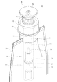
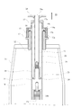
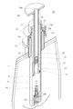
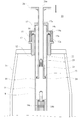
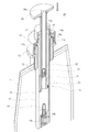
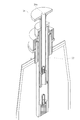
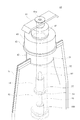
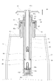
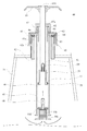
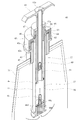
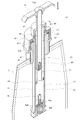
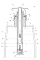
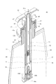
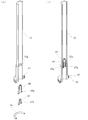
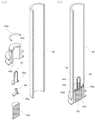
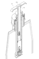
- FIG. 1 is a schematic perspective view of a main part of a first embodiment of a vacuum pump mechanism integrally mounted on a packaging material of the present invention. It is the schematic sectional drawing. It is the schematic perspective sectional drawing. It is a schematic sectional drawing which shows the state at the time of suction of an inner cylinder. It is the schematic perspective sectional drawing. It is a schematic sectional drawing which shows the state before discharge of an inner cylinder. It is the schematic perspective sectional drawing. It is a schematic sectional drawing which shows the state at the time of discharge of an inner cylinder. It is the schematic perspective sectional drawing.
- FIG. 3A is a schematic perspective sectional view showing a state where a check valve is about to be attached to an inner cylinder, and FIG. FIG.
- FIG. 3A shows a state in which a check valve is to be attached to a cylinder
- FIG. 3A is a schematic perspective sectional view before assembling
- FIG. 5A and 5B show a state in which the inner cylinder is about to be mounted on the cylinder
- FIG. 5A is a perspective sectional view before assembling
- FIG. It is a perspective sectional view showing the state where it is going to fit a cylinder in an outer frame.
- It is a schematic perspective sectional view which shows the state which attaches a cylinder to an outer frame, and is going to attach a cover member and a cap.
- It is a schematic perspective sectional view which shows the state which attached the cylinder to the outer frame, and attached the cover member and the cap.
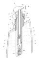
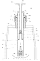
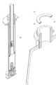
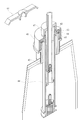
- FIG. 9 is a schematic perspective view of a principal part showing a second embodiment of the vacuum pump mechanism integrally mounted on the packaging material of the present invention. It is the schematic sectional drawing. It is the schematic perspective sectional drawing. It is a schematic sectional drawing which shows the state at the time of suction of an inner cylinder. It is the schematic perspective sectional drawing. It is a schematic sectional drawing which shows the state before discharge of an inner cylinder. It is the schematic perspective sectional drawing. It is a schematic sectional drawing which shows the state at the time of discharge of an inner cylinder. It is the schematic perspective sectional drawing. FIG.
- FIG. 3A is a schematic perspective sectional view showing a state where a check valve is about to be attached to an inner cylinder
- FIG. FIG. 3A shows a state in which a check valve is to be attached to a cylinder
- FIG. 3A is a schematic perspective sectional view before assembling
- FIG. 3A shows a state in which an inner cylinder is to be attached to a cylinder
- FIG. 3A is a schematic perspective sectional view before assembling
- FIG. It is a schematic perspective sectional view showing the state where the cylinder was fitted in the outer frame.
- FIG. 4 is a schematic perspective sectional view showing a state where a cylinder is to be mounted on an outer frame. It is a schematic perspective sectional view which shows the state which attached the cylinder to the outer frame, and attached the cover member and the cap. It is a schematic perspective sectional view in the state where the operation handle was assembled to the inner cylinder.
- a vacuum pump mechanism 10 integrally mounted on the packaging material of the first embodiment is used for mounting a packaging material 31 having a flange portion 13 on a side surface and a male screw portion 12a on an upper end.
- a cylinder 14 having a flange portion 14a at an upper portion thereof is mounted on the outer frame 12 via a flange portion 14a having a packing 14e provided on a lower surface, and is housed in the outer frame 12;
- a cover member 15 having a female screw portion 15a engaged with a male screw portion 12a of the outer frame 12 and having a through hole 16 of the cylinder 14 is engaged with the outer frame 12 via a flange portion 14a of the cylinder 14.
- the cylinder 14 is fixed to the outer frame 12.
- a cap 17 is attached to an opening at the upper end of the cylinder 14 protruding above the outer frame 12, an insertion hole 17 a of the inner cylinder 22 is provided in the cap 17, and a filter storage portion 14 b is provided at an end of the cylinder 14,
- the check valve 18 is protruded into the cylinder 14 so as to communicate with the filter 14c from the communication hole 14d of the filter accommodating portion 14b to form a fixing member 11.
- a partition plate 23 around which an O-ring 24 for sealing between the inner wall of the cylinder 14 is provided is provided at the lower end, and an inner cylinder 22 movably mounted in the cylinder 14 together with the partition plate 23.
- the check valve 25 is housed in the inner cylinder 22, and the upper end of the inner cylinder 22 is protruded from the insertion hole 17 a of the cap 17, and an operation handle 26 is attached to the end thereof to move them. This is a member 21.
- the operating member 26 is pulled up on the fixed member 11 to retract the movable member 21 from the state of FIGS. 2 and 3 to the stage of FIGS.
- the air in 31 is sucked into the cylinder 14 and then pushes the movable member 21 as shown in FIGS.
- the air in the cylinder 14 is discharged from the upper end opening of the inner cylinder 22 via the check valve 25, so that the piston movement of the movable member 21 is repeated.
- the air in the packaging material 31 is sucked and discharged.
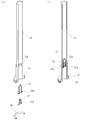
- FIGS. 10 to 16 are for explaining how to assemble each part in the present embodiment. That is, FIG. 10 shows how to attach the check valve 25 to the inner cylinder 22 provided with the inward flange portion 22a at the lower portion, and FIG. 10A shows a state before the assembling. (b) shows the state after assembly. The lower flange 25a of the check valve 25 is engaged with the outward flange 25a at the lower end of the check valve 25. It is installed from the part.
- reference numeral 23 denotes a partition plate around which an O-ring 24 is arranged.
- FIG. 11 shows how to attach the check valve 18 to the cylinder 14, FIG. 11 (a) shows a state before assembling, and FIG. 11 (b) shows a state after assembling. Things.
- a filter housing portion 14b provided with a communication hole 14d at the upper end is formed.
- the check valve 18 protrudes upward from the communication hole 14d to engage the lower end outward flange portion 18a with the communication hole 14d, and further has a cylindrical holding portion 28 provided with a flange portion 28a at the lower end. Is mounted from the lower opening of the check valve 18.
- reference numeral 14c denotes a filter.
- FIG. 12A and 12B show how the inner cylinder 22 is attached to the cylinder 14.
- FIG. 12A shows a state before the assembly
- FIG. 12B shows a state after the assembly. That is, when the inner cylinder 22 is fitted from the upper end opening of the cylinder 14, the O-ring 24 descends while being in close contact with the inner wall of the cylinder 14.
- FIG. 13 shows a state in which the cylinder 14 is about to be fitted into the outer frame 12.
- the cylinder 14 is engaged with the outer frame 12 via the flange portion 14 a of the cylinder 14.
- the upper and lid members 15 are attached and fixed.
- airtightness between the outer frame 12 and the cylinder 14 is maintained by the packing 14e provided on the lower surface of the flange portion 14a.
- 17 is a cap mounted on the upper end of the cylinder 14.
- FIG. 16 shows a state in which an operation handle 26 is further assembled to the inner cylinder 22.
- a disk-shaped operation handle 26 is used.
- Reference numeral 26a denotes an opening of the operation handle 26 which does not close the upper end opening of the inner cylinder 22.
- the vacuum pump mechanism 40 integrally mounted on the packaging material of the second embodiment is used for mounting the packaging material 31 having a flange portion 43 on the side surface and a male screw portion 42a on the upper end.
- the outer frame 42 is provided.
- the cylinder 44 having the cylindrical flange member 62 connected to the upper portion is mounted on the outer frame 42 via a packing 64 in which the flange 63 of the cylindrical flange member 62 is provided with a downwardly projecting ridge 65 at the center in the width direction.
- a female screw portion 45a that is housed in the outer frame 42 and is engaged with a male screw portion 42a provided on a flange portion 43 on the side surface of the outer frame 42, and an insertion hole 46 at the upper end of a cylindrical flange member 62 described below.
- the cylinder 44 is fixed to the outer frame 42 by engaging the lid member 45 having the above with the outer frame 42 via the flange portion 63 of the cylindrical flange member 62.
- Reference numeral 66 denotes a cylinder press-fit guide provided on the lower surface of the cylindrical flange member 62.
- a cap 47 is attached to an opening at the upper end of the cylindrical flange member 62 protruding above the outer frame 42, an insertion hole 47 a for the inner cylinder 52 is provided in the cap 47, and a filter housing member is provided at an end of the cylinder 44.
- the check valve 48 protrudes into the cylinder 44 so as to be in communication with the filter 44c of the filter housing member 44b.
- 44d is a ring-shaped packing attached to the upper part of the filter housing member 44b.
- a partition plate 57 around which an O-ring 58 for sealing the inner wall of the cylinder 44 is provided is provided at the lower end, and an inner cylinder 52 movably mounted in the cylinder 44 together with the partition plate 57.
- the check valve 60 is housed in the inner cylinder 52, and the upper end of the inner cylinder 52 is protruded from the insertion hole 47 a of the cap 47, and the operation handle 61 is attached to the end thereof to move them.
- FIGS. 26 to 32 are for explaining how to assemble each part in the present embodiment. That is, FIG. 26 shows how to attach the check valve 60 to the inner cylinder 52 provided with the inward flange portion 52a at the lower portion, and FIG. 26 (a) shows a state before the assembly, and FIG. (b) shows the state after assembly. Then, the outwardly-facing flange portion 60a at the lower end of the check valve 60 is engaged with the flange portion 52a, and the cylindrical holding portion 67 having a flange portion 67a at the lower end thereof is opened at the lower opening of the check valve 60. It is installed from the part.
- reference numeral 57 denotes a partition plate around which an O-ring 58 is arranged.
- FIG. 27 shows how to attach the check valve 48 to the cylinder 44.
- FIG. 27 (a) shows a state before the assembly and
- FIG. 27 (b) shows a state after the assembly. Things.
- a filter housing member 44b having a communication hole 44a at the upper end is fitted into the lower end of the cylinder 44.
- the check valve 48 protrudes upward from the communication hole 44a to engage the lower outward flange portion 48a with the communication hole 44a, and further has a cylindrical holding portion 68 provided with a lower flange portion 68a at the lower end thereof. Is mounted through the lower opening of the check valve 48.
- reference numeral 44c denotes a filter
- 44d denotes a ring-shaped packing attached to the upper part of the filter housing member 44b.
- FIG. 28A and 28B show how the inner cylinder 52 is attached to the cylinder 44.
- FIG. 28A shows a state before the assembling
- FIG. 28B shows a state after the assembling. That is, when the inner cylinder 52 is fitted through the upper end opening of the cylinder 44, the O-ring 58 descends while being in close contact with the inner wall of the cylinder 44. Then, the upper end of the cylinder 44 is press-fitted into the cylinder press-fit guide 66 of the cylindrical flange member 62 and attached.
- FIG. 29 shows a state in which the cylinder 44 is about to be fitted into the outer frame 42.
- the flange member 62 attached to the upper part of the cylinder 44 is mounted on the outer frame 42.
- the lid member 45 is attached and fixed.
- airtightness between the outer frame 42 and the cylinder 44 is maintained by the packing 64 provided on the lower surface of the flange portion 63.
- 47 is a cap mounted on the upper end of the cylinder 14.
- FIG. 32 shows a state in which an operation handle 61 is further assembled to the inner cylinder 52.
- a rod-shaped operation handle 61 is used.
- Reference numeral 61a denotes an opening of the operation handle 61 which does not close the upper end opening of the inner cylinder 52.
- the vacuum pump mechanism integrally mounted on the packaging material of the present invention can be used to prevent various contents stored in the packaging material from being oxidized or altered due to contact with air. It can be suitably applied as an attachment of a packaging material for various contents.
- Vacuum pump mechanism 11 integrally attached to packaging material 11 Fixing member 12 Outer frame 12a Male screw part 13 Flange part 14 Cylinder 14a Flange part 14b Filter storage part 14c Filter 14d Communication hole 14e Packing 15 Lid member 15a Female screw part 16 Insertion hole 17 Cap 17a Insertion hole 18 Check valve 18a Flange 21 Movable member 22 Inner tube 22a Flange 23 Partition plate 24 O-ring 25 Check valve 25a Flange 26 Operating handle 26a Opening 27 Tubular holding 27a Flange 28 tube Shaped holding part 28a Flange part 31 Packaging material 40 Vacuum pump mechanism 41 integrally attached to packaging material Fixed member 42 Outer frame 42a Male screw part 43 Flange part 44 Cylinder 44a Communication hole 44b Filter storage member 44c Filter 44d Ring packing 45 Cover Member 45a female Retaining portion 46 Insertion hole 47 Cap 47a Insertion hole 48 Check valve 48a Flange portion 51 Movable member 52 Inner tube 52a Flange portion 57 Partition plate 58 O-ring 60 Check valve 60
Landscapes
- Engineering & Computer Science (AREA)
- General Engineering & Computer Science (AREA)
- Mechanical Engineering (AREA)
- Packages (AREA)
- Sealing Devices (AREA)
- Vacuum Packaging (AREA)
Abstract
Le problème décrit par la présente invention est de fournir un mécanisme de pompe à vide apte à agrandir la surface d'une ouverture afin de permettre à un contenu d'être stocké rapidement dans un récipient. La solution de l'invention porte sur un mécanisme de pompe à vide caractérisé en ce qu'il comprend : un élément fixe qui est formé par fixation d'un cylindre sur un cadre externe par l'intermédiaire d'une section bride, par immobilisation du cylindre sur le cadre externe par mise en prise d'un élément couvercle, qui a une partie filetage femelle destinée à venir en prise avec une partie filetage mâle du cadre externe, avec le cadre externe par l'intermédiaire de la section bride, par fixation d'un capuchon à une partie ouverture de l'extrémité supérieure du cylindre dépassant au-dessus du cadre externe, par fourniture d'un trou traversant destiné à un tube interne dans le capuchon, par fourniture d'une section logement de filtre sur une partie extrémité du cylindre, et par installation d'un clapet de non-retour avançant dans le cylindre de sorte qu'il y ait une communication avec une partie filtre de la section logement de filtre; et un élément mobile qui est formé par fourniture du tube interne, qui est ajusté mobile dans le cylindre, par logement d'un clapet de non-retour dans le tube interne, par installation de l'extrémité supérieure du tube interne dépassant du trou traversant du capuchon, et par fixation d'une poignée de manipulation à l'extrémité supérieure.
Applications Claiming Priority (2)
| Application Number | Priority Date | Filing Date | Title |
|---|---|---|---|
| JP2018-187969 | 2018-10-03 | ||
| JP2018187969A JP6534237B1 (ja) | 2018-10-03 | 2018-10-03 | 包材に一体的に装着した真空ポンプ機構 |
Publications (1)
| Publication Number | Publication Date |
|---|---|
| WO2020071238A1 true WO2020071238A1 (fr) | 2020-04-09 |
Family
ID=67023717
Family Applications (1)
| Application Number | Title | Priority Date | Filing Date |
|---|---|---|---|
| PCT/JP2019/037890 Ceased WO2020071238A1 (fr) | 2018-10-03 | 2019-09-26 | Mécanisme de pompe à vide fixé d'un seul tenant à un matériau d'emballage |
Country Status (2)
| Country | Link |
|---|---|
| JP (1) | JP6534237B1 (fr) |
| WO (1) | WO2020071238A1 (fr) |
Families Citing this family (4)
| Publication number | Priority date | Publication date | Assignee | Title |
|---|---|---|---|---|
| JP7329065B2 (ja) * | 2019-03-22 | 2023-08-17 | イリノイ トゥール ワークス インコーポレイティド | 真空埋込システムの流体流量制御 |
| US11714032B2 (en) | 2019-03-22 | 2023-08-01 | Illinois Tool Works Inc. | Vacuum systems for epoxy mounting of material samples |
| JP2024000686A (ja) * | 2022-06-21 | 2024-01-09 | 株式会社パックプラス | プッシュポンプおよび包装容器 |
| CN121849517B (zh) * | 2026-03-19 | 2026-07-17 | 中化地质矿山总局内蒙古地质勘查院 | 一种地质勘探样品储存箱 |
Citations (5)
| Publication number | Priority date | Publication date | Assignee | Title |
|---|---|---|---|---|
| JP2003075228A (ja) * | 2001-09-07 | 2003-03-12 | Tadashi Hagiwara | 定量計量真空分配器 |
| FR2871442A1 (fr) * | 2004-06-11 | 2005-12-16 | Franck Sauvage | Dispositif de bouchage pour une bouteille munie d'un goulot |
| US20060120632A1 (en) * | 2004-12-03 | 2006-06-08 | Ngai Han | Vacuum packaging bags equipped with deflating device and deflating cylinders for use thereof |
| JP2014069881A (ja) * | 2012-09-29 | 2014-04-21 | Ko Shitsufun | 真空ポンプ機構 |
| JP2015160612A (ja) * | 2014-02-25 | 2015-09-07 | 瑟芬 洪 | 逆止弁付き包材 |
-
2018
- 2018-10-03 JP JP2018187969A patent/JP6534237B1/ja active Active
-
2019
- 2019-09-26 WO PCT/JP2019/037890 patent/WO2020071238A1/fr not_active Ceased
Patent Citations (5)
| Publication number | Priority date | Publication date | Assignee | Title |
|---|---|---|---|---|
| JP2003075228A (ja) * | 2001-09-07 | 2003-03-12 | Tadashi Hagiwara | 定量計量真空分配器 |
| FR2871442A1 (fr) * | 2004-06-11 | 2005-12-16 | Franck Sauvage | Dispositif de bouchage pour une bouteille munie d'un goulot |
| US20060120632A1 (en) * | 2004-12-03 | 2006-06-08 | Ngai Han | Vacuum packaging bags equipped with deflating device and deflating cylinders for use thereof |
| JP2014069881A (ja) * | 2012-09-29 | 2014-04-21 | Ko Shitsufun | 真空ポンプ機構 |
| JP2015160612A (ja) * | 2014-02-25 | 2015-09-07 | 瑟芬 洪 | 逆止弁付き包材 |
Also Published As
| Publication number | Publication date |
|---|---|
| JP6534237B1 (ja) | 2019-06-26 |
| JP2020055606A (ja) | 2020-04-09 |
Similar Documents
| Publication | Publication Date | Title |
|---|---|---|
| JP6534237B1 (ja) | 包材に一体的に装着した真空ポンプ機構 | |
| EP1020371A2 (fr) | Recipient sous-vide et étanche | |
| KR101033754B1 (ko) | 액체용기의 배출펌프 | |
| JP5542185B2 (ja) | 真空ポンプ機構 | |
| KR20120006523A (ko) | 펌프 장치 및 그의 제조방법 | |
| JP5992242B2 (ja) | 注出キャップ及びそれを有する容器 | |
| JP2009056372A (ja) | トリガー式噴出器 | |
| US11034503B1 (en) | Container for mixing heterogeneous contents | |
| US5232016A (en) | Vacuum storage container | |
| JP2010012365A (ja) | 液体噴出器 | |
| WO2018212036A1 (fr) | Récipient d'éjection de fluide | |
| JP5268451B2 (ja) | 液体噴出器 | |
| JP7313248B2 (ja) | スポイト容器 | |
| JP4925165B2 (ja) | 蓋付き高気密容器 | |
| CN212661329U (zh) | 真空化妆品容器 | |
| EP1041656A3 (fr) | Accumulateur étanche comportant un système de ventilation | |
| KR200475969Y1 (ko) | 벤딩형 스템구조가 구비된 펌프 | |
| JP2021091473A (ja) | スポイト容器 | |
| US20080105706A1 (en) | Depress-to-actuate pneumatically-operated double-walled container | |
| JP6421079B2 (ja) | スポイト容器 | |
| JP2014213940A (ja) | 吐出容器 | |
| JP3224712U (ja) | 保存容器用密閉構造及び保存容器 | |
| JP2007314233A (ja) | 蓋付き高気密容器 | |
| JP2006182425A (ja) | キャップ | |
| KR200423625Y1 (ko) | 화장품용기 |
Legal Events
| Date | Code | Title | Description |
|---|---|---|---|
| 121 | Ep: the epo has been informed by wipo that ep was designated in this application |
Ref document number: 19869216 Country of ref document: EP Kind code of ref document: A1 |
|
| NENP | Non-entry into the national phase |
Ref country code: DE |
|
| 122 | Ep: pct application non-entry in european phase |
Ref document number: 19869216 Country of ref document: EP Kind code of ref document: A1 |