WO2020071374A1 - Dispositif de surveillance d'état et procédé de surveillance d'état - Google Patents
Dispositif de surveillance d'état et procédé de surveillance d'étatInfo
- Publication number
- WO2020071374A1 WO2020071374A1 PCT/JP2019/038774 JP2019038774W WO2020071374A1 WO 2020071374 A1 WO2020071374 A1 WO 2020071374A1 JP 2019038774 W JP2019038774 W JP 2019038774W WO 2020071374 A1 WO2020071374 A1 WO 2020071374A1
- Authority
- WO
- WIPO (PCT)
- Prior art keywords
- state
- spectrum data
- subject
- value
- predetermined value
- Prior art date
- Legal status (The legal status is an assumption and is not a legal conclusion. Google has not performed a legal analysis and makes no representation as to the accuracy of the status listed.)
- Ceased
Links
Images






Classifications
-
- A—HUMAN NECESSITIES
- A61—MEDICAL OR VETERINARY SCIENCE; HYGIENE
- A61B—DIAGNOSIS; SURGERY; IDENTIFICATION
- A61B5/00—Measuring for diagnostic purposes; Identification of persons
-
- A—HUMAN NECESSITIES
- A61—MEDICAL OR VETERINARY SCIENCE; HYGIENE
- A61B—DIAGNOSIS; SURGERY; IDENTIFICATION
- A61B5/00—Measuring for diagnostic purposes; Identification of persons
- A61B5/103—Measuring devices for testing the shape, pattern, colour, size or movement of the body or parts thereof, for diagnostic purposes
- A61B5/11—Measuring movement of the entire body or parts thereof, e.g. head or hand tremor or mobility of a limb
-
- A—HUMAN NECESSITIES
- A61—MEDICAL OR VETERINARY SCIENCE; HYGIENE
- A61B—DIAGNOSIS; SURGERY; IDENTIFICATION
- A61B5/00—Measuring for diagnostic purposes; Identification of persons
- A61B5/103—Measuring devices for testing the shape, pattern, colour, size or movement of the body or parts thereof, for diagnostic purposes
- A61B5/11—Measuring movement of the entire body or parts thereof, e.g. head or hand tremor or mobility of a limb
- A61B5/113—Measuring movement of the entire body or parts thereof, e.g. head or hand tremor or mobility of a limb occurring during breathing
-
- A—HUMAN NECESSITIES
- A61—MEDICAL OR VETERINARY SCIENCE; HYGIENE
- A61B—DIAGNOSIS; SURGERY; IDENTIFICATION
- A61B5/00—Measuring for diagnostic purposes; Identification of persons
- A61B5/16—Devices for psychotechnics; Testing reaction times ; Devices for evaluating the psychological state
-
- G—PHYSICS
- G08—SIGNALLING
- G08B—SIGNALLING SYSTEMS, e.g. PERSONAL CALLING SYSTEMS; ORDER TELEGRAPHS; ALARM SYSTEMS
- G08B21/00—Alarms responsive to a single specified undesired or abnormal condition and not otherwise provided for
- G08B21/18—Status alarms
- G08B21/22—Status alarms responsive to presence or absence of persons
-
- G—PHYSICS
- G08—SIGNALLING
- G08B—SIGNALLING SYSTEMS, e.g. PERSONAL CALLING SYSTEMS; ORDER TELEGRAPHS; ALARM SYSTEMS
- G08B25/00—Alarm systems in which the location of the alarm condition is signalled to a central station, e.g. fire or police telegraphic systems
- G08B25/01—Alarm systems in which the location of the alarm condition is signalled to a central station, e.g. fire or police telegraphic systems characterised by the transmission medium
- G08B25/04—Alarm systems in which the location of the alarm condition is signalled to a central station, e.g. fire or police telegraphic systems characterised by the transmission medium using a single signalling line, e.g. in a closed loop
Definitions
- the present disclosure relates to a state monitoring device that monitors the safety of a resident.
- Patent Document 1 proposes a monitoring system that monitors the state of an elderly person or the like by using IT (Information @ Technology). When a trouble or the like occurs in the subject, a caregiver, a nurse, and the like can promptly provide assistance and the like.
- an information processing apparatus that displays a state of a subject on a screen in real time and displays an event different from a normal state, that is, a state of the subject in which the event occurs.
- Patent Document 2 a monitoring device that collects biological information of a subject and monitors the safety of the subject is irradiated with microwaves to the subject, and the Doppler shift is performed.
- a method is disclosed in which the body motion and respiration of the subject are detected from the reflected waves, and the safety of the subject is monitored based on the number of body motions and the respiration rate within a predetermined time.
- JP 2017-174012 A Japanese Patent No. 5682504
- the present disclosure has been made in view of the above background, and an object in one aspect is to provide a state monitoring device and a state monitoring method capable of determining a state of a subject with high accuracy. .
- the condition monitoring device irradiates the subject with microwaves, and detects a reflected wave detected by the subject, and analyzes the reflected wave detected by the detecting unit.
- An analysis unit that acquires the spectrum data of the respiratory signal, and a determination unit that determines the sleep state of the subject based on the spectrum data of the respiratory signal.
- the determining unit determines that the sleep state is awake when the waveform line width of the respiratory signal spectrum data is larger than a predetermined value, and determines the sleep state when the waveform line width of the respiratory signal spectral data is equal to or less than the predetermined value. It is determined that the time is in a resting state.
- the spectral data of the respiratory signal has a peak value every predetermined period.
- the determination unit normalizes the maximum value of the peak value for each predetermined period to a predetermined value, determines that the awake state during sleep is determined when the waveform line width of the spectrum data of the respiration signal is larger than the predetermined value, and determines the spectrum of the respiration signal.
- the waveform line width of the data is equal to or smaller than a predetermined value, it is determined that the sleeping state is at rest.
- the determining unit generates power spectrum data of the respiratory signal, determines whether the power spectrum data is equal to or greater than a predetermined value, and determines whether the subject is present when the power spectrum data is equal to or greater than the predetermined value. It is determined as a room state, and when the power spectrum data is less than a predetermined value, it is determined that the subject is absent.
- the spectrum data of the respiratory signal is divided into a frequency region indicating a peak value and other frequency regions, and the determining unit calculates the power integrated value of the spectrum data of the frequency region indicating the peak value and the other values.
- the ratio or the difference with the power integrated value of the spectrum data in the frequency domain is equal to or more than a predetermined value, it is determined that the user is in the awake state during sleep, and when the ratio or the difference is less than the predetermined value, the rest state during sleep is determined. Is determined.
- the condition monitoring method includes irradiating a subject with microwaves to detect a reflected wave reflected from the subject, and analyzing the detected reflected wave to obtain a spectrum of a respiratory signal.
- the method includes acquiring data and determining a sleep state of the subject based on the spectrum data of the respiratory signal.
- the step of determining the sleep state of the subject includes determining the awake state during sleep when the waveform line width of the respiratory signal spectral data is larger than a predetermined value, and determining the respiratory signal spectral data waveform line width. Is smaller than or equal to a predetermined value, it is determined that the sleeping state is at rest.
- the spectrum data of the respiratory signal has a peak value every predetermined period.
- the maximum value of the peak value for each predetermined period is normalized to a predetermined value, and when the waveform line width of the spectrum data of the respiration signal is larger than the predetermined value, it is determined that the user is in the awake state during sleep, and the waveform line of the spectrum data of the respiration signal is obtained.
- the width is equal to or less than a predetermined value, it is determined that the sleeping state is at rest.
- the spectrum data of the respiratory signal is divided into a frequency domain showing a peak value and other frequency domains.
- the ratio or difference between the power integrated value of the spectrum data in the frequency domain indicating the peak value and the power integrated value of the spectrum data in the other frequency domains is equal to or greater than a predetermined value. In this case, it is determined that the user is in the awake state during sleep, and when the ratio or the difference is less than the predetermined value, it is determined that the user is in the rest state during sleep.
- FIG. 1 is a diagram illustrating an example of a configuration of a watching system.
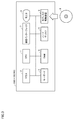
- FIG. 1 is a block diagram illustrating an outline of a configuration of a watching system.
- FIG. 3 is a block diagram illustrating a hardware configuration of a computer system 300 functioning as a cloud server 150. It is a figure showing an example of the outline of the device composition of watching system 100 using sensor box 119. It is a figure explaining sensor data in a resting state at the time of sleep of a subject acquired by sensor box 119 based on an embodiment. It is a figure explaining sensor data in an awake state at the time of sleep of a subject acquired by sensor box 119 based on an embodiment.
- FIG. 3 is a diagram illustrating power spectrum data based on the embodiment. It is a figure explaining change of power integrated value other than near a peak value according to a modification of an embodiment. It is a figure explaining the judgment of the rest state and the awake state at the time of sleep.
- a respiratory signal is measured as biological information of a target person such as a resident of the facility, and the daily state of the target person can be accurately grasped.
- the measurement is performed in a state where the subject is not conscious of the measurement.
- FIG. 1 is a diagram illustrating an example of the configuration of the watching system 100.
- the watching target is, for example, a resident in each living room provided in the living room area 180 of the facility.
- living rooms 110 and 120 are provided in a living room area 180.
- the living room 110 is assigned to the resident 111.
- the living room 120 is assigned to the resident 121.
- the number of living rooms included in the watching system 100 is two, but the number is not limited to this.
- Network 190 may include both an intranet and the Internet.
- the portable terminal 143 carried by the caregiver 141 and the portable terminal 144 carried by the caregiver 142 can be connected to the network 190 via the access point 140. Further, the sensor box 119, the management server 200, and the access point 140 can communicate with the cloud server 150 via the network 190.
- Each of the living rooms 110 and 120 includes a closet 112, a bed 113, and a toilet 114 as facilities.
- the door of the living room 110 is provided with a door sensor 118 that detects opening and closing of the door.
- a toilet sensor 116 that detects the opening and closing of the toilet 114 is installed on the door of the toilet 114.
- the bed 113 is provided with an odor sensor 117 for detecting the odor of each of the residents 111 and 121.
- each of the residents 111 and 121 can operate the care call slave unit 115, respectively.
- the sensor box 119 has a built-in sensor for detecting the behavior of an object in the living rooms 110 and 120.
- a sensor is a Doppler sensor for detecting the movement of an object.
- a camera is another example.
- the sensor box 119 may include both a Doppler sensor and a camera as sensors.
- FIG. 2 is a block diagram illustrating an outline of a configuration of the watching system 100.
- the sensor box 119 includes a control device 101, a read only memory (ROM) 102, a random access memory (RAM) 103, a communication interface 104, a camera 105, a Doppler sensor 106, a wireless communication device 107, and a storage device. 108.
- the control device 101 controls the sensor box 119.
- the control device 101 is composed of, for example, at least one integrated circuit.
- the integrated circuit is, for example, at least one CPU (Central Processing Unit), MPU (Micro Processing Unit) or another processor, at least one ASIC (Application Specific Integrated Circuit), at least one FPGA (Field Programmable Gate Array), or these. And the like.
- An antenna (not shown) and the like are connected to the communication interface 104.
- the sensor box 119 exchanges data with an external communication device via the antenna.
- External communication devices include, for example, the management server 200, the mobile terminals 143, 144 and other terminals, the access point 140, the cloud server 150, and other communication terminals.
- the camera 105 is a near-infrared camera in one implementation.
- the near-infrared camera includes an IR (Infrared) projector that emits near-infrared light.
- IR Infrared
- camera 105 is a surveillance camera that receives only visible light.
- a 3D sensor or a thermographic camera may be used as camera 105.
- the sensor box 119 and the camera 105 may be configured integrally or may be configured separately.
- the Doppler sensor 106 is, for example, a microwave Doppler sensor, and emits and receives radio waves to detect the behavior (movement) of an object in the living rooms 110 and 120. Thereby, the biological information of the resident 111, 121 of the living room 110, 120 can be detected.
- the Doppler sensor 106 emits microwaves in the 24 GHz band toward the beds 113 of the rooms 110 and 120 and receives reflected waves reflected by the residents 111 and 121. The reflected waves are Doppler shifted by the actions of the residents 111 and 121.
- the Doppler sensor 106 can detect the respiratory state and the heart rate of the residents 111 and 121 from the reflected waves.
- the wireless communication device 107 receives signals from the care call slave device 240, the door sensor 118, the toilet sensor 116, and the odor sensor 117, and transmits the signals to the control device 101.
- the care call slave unit 240 includes a care call button 241. When the button is operated, the care call slave device 240 transmits a signal indicating that the operation has been performed to the wireless communication device 107.
- the door sensor 118, the toilet sensor 116, and the odor sensor 117 transmit the respective detection results to the wireless communication device 107.
- the storage device 108 is, for example, a fixed storage device such as a flash memory or a hard disk, or a recording medium such as an external storage device.
- the storage device 108 stores a program executed by the control device 101 and various data used for executing the program.
- the various data may include the behavior information of the residents 111 and 121.
- At least one of the above-described programs and data is a storage device other than the storage device 108 (for example, a storage area (for example, a cache memory or the like) of the control device 101, a ROM 102,
- the RAM 103 may be stored in an external device (for example, the management server 200 or the mobile terminals 143 and 144).
- the mobile terminals 143 and 144 include a control device 221, a ROM 222, a RAM 223, a communication interface 224, a display 226, a storage device 228, and an input device 229.
- the mobile terminals 143 and 144 are realized as, for example, a smartphone, a tablet terminal, a wristwatch-type terminal, or another wearable device.
- the control device 221 controls the mobile terminals 143 and 144.
- the control device 221 is configured by, for example, at least one integrated circuit.
- the integrated circuit includes, for example, at least one CPU, at least one ASIC, at least one FPGA, or a combination thereof.
- the mobile terminals 143 and 144 exchange data with an external communication device via the antenna and the access point 140.
- the external communication device includes, for example, the sensor box 119, the management server 200, and the like.
- the display 226 is realized by, for example, a liquid crystal display, an organic EL (Electroluminescence) display, or the like.
- the input device 229 is realized by, for example, a touch sensor provided on the display 226. The touch sensor receives a touch operation on the mobile terminals 143 and 144, and outputs a signal corresponding to the touch operation to the control device 221.
- the storage device 228 is realized by, for example, a flash memory, a hard disk or another fixed storage device, or a removable data recording medium.
- the management server 200 includes an analysis unit 202 and a determination unit 204.
- the analysis unit 202 and the determination unit 204 are realized by the CPU executing a program stored in the memory.
- the analysis unit 202 reads the sensor data stored in the hard disk 5 of the cloud server 150 and acquires the spectrum data of the respiration signal.
- the determination unit 204 determines the state or the like of the subject based on the spectrum data of the respiratory signal.
- FIG. 3 is a block diagram illustrating a hardware configuration of computer system 300 functioning as cloud server 150.
- the computer system 300 includes, as main components, a CPU 1 for executing a program, a mouse 2 and a keyboard 3 for receiving an instruction input by a user of the computer system 300, and data generated by executing the program by the CPU 1 or a mouse 2.
- a RAM 4 for volatilely storing data input via the keyboard 3
- a hard disk 5 for nonvolatilely storing data
- an optical disk drive 6 a communication interface (I / F) 7, and a monitor 8 Including.
- Each component is mutually connected by a data bus.
- the optical disk drive 6 is loaded with a CD-ROM 9 and other optical disks.
- the processing in the computer system 300 is realized by each hardware and software executed by the CPU 1.
- Such software may be stored in the hard disk 5 in advance.
- the software is stored on a CD-ROM 9 or another recording medium and is distributed as a computer program.
- the software may be provided as a downloadable application program by an information provider connected to the so-called Internet.
- Such software is temporarily stored in the hard disk 5 after being read from the recording medium by the optical disk drive 6 or another reading device, or downloaded via the communication interface 7.
- the software is read from the hard disk 5 by the CPU 1 and stored in the RAM 4 in the form of an executable program.
- CPU 1 executes the program.
- Each component constituting the computer system 300 shown in FIG. 3 is a general one. Therefore, it can be said that one of the essential parts of the technical idea according to the present disclosure is software stored in the RAM 4, the hard disk 5, the CD-ROM 9, or another recording medium, or software downloadable via a network.
- the storage medium may include a non-transitory, computer-readable data storage medium. Since the operation of each piece of hardware of computer system 300 is well known, detailed description will not be repeated.
- the recording medium is not limited to a CD-ROM, FD (Flexible Disk), or hard disk, but may be a magnetic tape, a cassette tape, an optical disk (MO (Magnetic Optical Disc) / MD (Mini Disc) / DVD (Digital Versatile Disc)). , IC (Integrated Circuit) card (including memory card), optical card, mask ROM, EPROM (Electronically Programmable Read-Only Memory), EEPROM (Electronically Erasable Programmable Read-Only Memory), and fixing of semiconductor memory such as flash ROM It may be a medium that carries the program.
- IC Integrated Circuit
- the program mentioned here includes not only a program directly executable by the CPU but also a program in a source program format, a compressed program, an encrypted program, and the like.
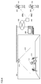
- FIG. 4 is a diagram illustrating an example of a schematic device configuration of the watching system 100 using the sensor box 119.
- the watching system 100 is used for watching the residents 111 and 121 who are the monitoring targets (monitoring targets) and other residents. As shown in FIG. 4, a sensor box 119 is attached to the ceiling of the living room 110. Sensor boxes 119 are similarly attached to other rooms.
- the range 410 represents the detection range of the sensor box 119.
- the Doppler sensor detects a person's behavior occurring in the area 410.
- the sensor box 119 has a camera as a sensor, the camera captures an image in the range 410.
- the sensor box 119 is installed in, for example, a nursing facility, a medical facility, a house, or the like. In the example of FIG. 4, the sensor box 119 is attached to the ceiling, and the resident 111 and the bed 113 are photographed from the ceiling. The place where the sensor box 119 is attached is not limited to the ceiling, and may be attached to the side wall of the living room 110.
- the watching system 100 detects a danger occurring to the resident 111 based on a series of images (that is, videos) obtained from the camera 105.
- the detectable danger includes a fall of the resident 111 and a state where the resident 111 is at a danger location (for example, a bed fence).
- the monitoring system 100 When the monitoring system 100 detects that the resident 111 is in danger, the monitoring system 100 notifies the caregivers 141, 143, and the like of that. As an example of the notification method, the watching system 100 notifies the danger of the resident 111 to the portable terminals 143 and 144 of the caregivers 141 and 142. Upon receiving the notification, the mobile terminals 143 and 144 notify the caregivers 141 and 142 of the danger of the resident 111 by a message, voice, vibration, or the like. Thus, the caregivers 141 and 142 can immediately recognize that the resident 111 is in danger, and can rush to the resident 111 quickly.
- FIG. 4 shows an example in which the watching system 100 includes one sensor box 119, but the watching system 100 may include a plurality of sensor boxes 119.
- FIG. 4 illustrates an example in which the watching system 100 includes a plurality of mobile terminals 143 and 144. However, the watching system 100 can be realized by a single mobile terminal.
- the communication interface 104 of the sensor box 119 in this example transmits the sensor data acquired by the Doppler sensor 106 to the cloud server 150.
- the cloud server 150 stores the data on the hard disk 5 as an example.
- the management server 200 reads out the sensor data stored in the hard disk 5 of the cloud server 150 and executes a predetermined process. In this example, the state of the subject is determined.
- the subject is awake or at rest during sleep, and whether the subject is in the room or absent.
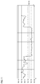
- FIG. 5 is a diagram illustrating sensor data in a resting state during sleep of the subject acquired by the sensor box 119 based on the embodiment.
- the reflected wave of the microwave by the Doppler sensor is detected.
- the subject is in a resting state while sleeping on the bed, there are few movements other than the breathing movement. Therefore, a signal having a small amplitude and a constant period of the reflected wave is detected in accordance with the movement of the breathing motion.
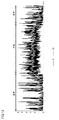
- FIG. 6 is a diagram illustrating sensor data in the awake state during sleep of the subject acquired by the sensor box 119 based on the embodiment.
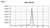
- FIG. 7 is a diagram illustrating the spectrum data of the sensor data when the user is in a resting state during sleep based on the embodiment.
- the analysis unit 202 of the management server 200 reads out the sensor data of FIG. 5 stored in the hard disk 5 of the cloud server 150 and acquires the spectrum data of the respiratory signal.
- the horizontal axis represents the respiratory rate (times / minute), and the vertical axis represents the signal intensity. If the user is in a resting state during sleep, a substantially constant cycle is detected in accordance with the breathing motion. In this example, a case where the peak value of the sensor data is detected at the position of 19 times / minute is shown.
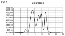
- FIG. 8 is a diagram illustrating the spectrum data of the sensor data when the user is in the awake state during sleep based on the embodiment.
- the analysis unit 202 of the management server 200 reads out and analyzes the sensor data of FIG. 6 stored in the hard disk 5 of the cloud server 150, and acquires the spectrum data of the respiratory signal.
- the horizontal axis indicates the respiratory rate (times / minute), and the vertical axis indicates the signal intensity.
- a plurality of peak waveforms are detected in accordance with other operations in addition to the respiratory operation.
- the waveform of the respiration rate (times / minute) corresponding to the highest peak value is 13 times / minute.
- the signal strength differs between the resting state during sleep and the awake state. Between the resting state during sleep and the awake state, the signal strength is larger in the rest state during sleep than in the awake state. This is because the maximum value differs depending on the distance between the subject and the sensor box 119 and the direction of movement. Therefore, the signal strength in the awake state is smaller than that in the rest state during sleep, so that it may be difficult to determine the awake state.
- a process of normalizing the maximum value of the peak signal intensity to 1 every predetermined period is executed.
- the maximum value of the peak value is normalized to 1 during the period in which the signal strength is different, and it becomes easy to compare the waveform shapes in the resting state and the awake state.
- FIG. 9 is a diagram illustrating a method for determining a resting state during sleep based on the embodiment. This is mainly processing in the determination unit 204.
- the vertical axis indicates a state in which the maximum value of the peak value of the signal strength is normalized to 1. Then, the waveform line width near the peak value of the spectrum data is detected, and it is determined whether the waveform line width is equal to or smaller than a predetermined value. When the waveform line width is narrower than the predetermined value as in this example, it can be determined that the sleeping state is at rest.
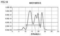
- FIG. 10 is a diagram illustrating a method for determining the awake state during sleep based on the embodiment.
- the vertical axis indicates a state where the maximum value of the peak value of the signal strength is normalized to 1.
- the waveform line width near the peak value of the spectrum data is detected, and it is determined whether the waveform line width is equal to or smaller than a predetermined value. If the waveform line width is wider than a predetermined value as in this example, it can be determined that the user is in the awake state during sleep.
- the present invention is not limited to this, and the detection may be performed at another position. Further, a predetermined value serving as a threshold may be changed at the position of the strength of the signal to be detected.
- the method makes a comparison and determination in a state where the peak value of the signal strength is normalized to 1, thereby providing a highly accurate subject. Can be determined.
- FIG. 11 is a diagram illustrating power spectrum data based on the embodiment. 11, the determination unit 204 of the management server 200 generates power spectrum data based on the spectrum data of the sensor data.
- the power in a predetermined range including the peak value of the sensor data is the sum of the power in a predetermined range including the peak value of the sensor data.
- a peak value of 19 times / minute is detected as an example of the spectrum data of the sensor data
- the power in the range of four times (15 to 23 times / minute) before and after as the predetermined range is obtained. Is calculated. In this case, for example, 5.8E + 11 is calculated.
- the determination unit 204 determines that the power spectrum data greater than the threshold is the presence of the subject (occupied in the room) and determines that the power spectrum data is lower than the threshold.
- the power spectrum data can be determined as the absence (absence) of the subject.
- the subject exists in the time zone where the power spectrum data is equal to or more than 1E + 10 as a threshold, and otherwise the subject is absent, so the data in the time zone (absence) is ignored. Is possible.
- the determination is made based on a comparison between the power in a predetermined range including the peak value of the spectrum data of the sensor data and the power in a region other than the predetermined range.
- the power integrated value in the vicinity of the peak value in the resting state during sleep (a range of four times before and after 15 to 23 times / minute) is 1.862.
- the total power integrated value (0 to 35 times / minute) is calculated, it is 1.956.
- the power integrated value near the peak value is subtracted from the total power integrated value.
- the power integrated value calculated near the peak value of the awake state during sleep (range of 4 times before and after 9 to 17 times / minute) is 4.382.
- the total power integrated value (0 to 35 times / minute) is calculated, it is 8.922.
- the power integrated value near the peak value is subtracted from the total power integrated value.
- FIG. 12 is a diagram illustrating a change in the integrated power value other than near the peak value according to the modification of the embodiment.
- the determination unit 204 generates data of the fluctuation of the power integrated value according to the above method.
- the determination unit 204 sets the threshold value to 1 in this example, and determines whether the user is in the awake state or in the resting state during sleep based on whether or not the average value is the threshold value (“1”). Is determined.
- the sleep state is determined. Therefore, the determination is made during the period when the subject is in the room, and is not determined when the subject is absent.
- FIG. 12 shows, as an example, a case where the user is present in the room and a case where the user is absent, and determines the sleep state when the user is present. This is mainly processing in the determination unit 204.
- FIG. 13 is a diagram illustrating determination of a resting state and an awake state during sleep. Referring to FIG. 13, it is determined whether or not the power integrated value in FIG. 12 is equal to or smaller than a threshold ("1"). If it is less than or equal to the threshold value ("1"), it is determined that it is in a resting state, and if it exceeds the threshold value ("1"), it is determined that it is in an awake state.
- a threshold a threshold
- ⁇ It is possible to grasp the state of the subject during sleep based on the determination result. That is, if the period of the resting state during sleep is long, it is possible to determine that the sleeping state is good. For example, it is possible to determine whether or not a good sleep state is based on whether or not a rest state during sleep for a predetermined period or more is secured.
- a sleep state is bad based on whether or not a wakeful state during sleep for a predetermined period or more is pending.
- the ratio between the power integrated value near the peak value and the power integrated value other than near the peak value may be calculated. In the case of a resting state during sleep, the ratio becomes 0 because the power integrated value other than near the peak value becomes small. On the other hand, in the awake state during sleep, the ratio approaches 1 because the power integrated value other than near the peak value increases.
- a resting state or awake state during sleep may be determined by comparison with a predetermined threshold value.
- the signal level of the biological information of the subject is determined based on a comparison between the power of the predetermined range including the peak value of the spectrum data and the power of the region other than the predetermined range. It is possible to grasp the state of the subject with high accuracy even in a low case.
- the management server 200 includes the analysis unit 202 and the determination unit 204 has been described.
- the present invention is not particularly limited to this, and a single state monitoring device may be provided by providing the sensor box 119 with the function. Of course it is possible.
- This technology is applicable to information obtained in hospitals, nursing homes, nursing homes and other facilities.
- 100 system 101,221 control device, 106 Doppler sensor, 107 wireless communication device, 108 storage device, 109 door, 110,120 living room, 111, 121, 910, 920, 930, 950 resident, 112 closet, 113 bed, 114 toilet, 115 care call handset, 116 toilet sensor, 117 sensor, 118 door sensor, 119 sensor box, 130 management center, 140 access point, 141, 142 caregiver, 143, 144 mobile terminal, 150 cloud server, 190 network, 200 management server, 226 display, 229 input device, 241 care call button, 290 vital sensor, 300 computer system.
Landscapes
- Health & Medical Sciences (AREA)
- Life Sciences & Earth Sciences (AREA)
- Physics & Mathematics (AREA)
- Engineering & Computer Science (AREA)
- Animal Behavior & Ethology (AREA)
- Public Health (AREA)
- Veterinary Medicine (AREA)
- General Health & Medical Sciences (AREA)
- Surgery (AREA)
- Molecular Biology (AREA)
- Medical Informatics (AREA)
- Heart & Thoracic Surgery (AREA)
- Biomedical Technology (AREA)
- Pathology (AREA)
- Biophysics (AREA)
- Business, Economics & Management (AREA)
- Oral & Maxillofacial Surgery (AREA)
- Dentistry (AREA)
- Emergency Management (AREA)
- Physiology (AREA)
- General Physics & Mathematics (AREA)
- Psychiatry (AREA)
- Developmental Disabilities (AREA)
- Educational Technology (AREA)
- Child & Adolescent Psychology (AREA)
- Hospice & Palliative Care (AREA)
- Psychology (AREA)
- Social Psychology (AREA)
- Measurement Of The Respiration, Hearing Ability, Form, And Blood Characteristics Of Living Organisms (AREA)
- Measurement And Recording Of Electrical Phenomena And Electrical Characteristics Of The Living Body (AREA)
Abstract
L'invention concerne un dispositif de surveillance d'état qui permet de déterminer avec une grande précision l'état d'un sujet. La présente invention concerne un dispositif de surveillance d'état qui comprend: une partie de détection qui rayonne des micro-ondes au niveau d'un sujet et détecte des ondes réfléchies qui ont été réfléchies par le sujet; une partie d'analyse qui analyse les ondes réfléchies détectées par la partie de détection pour acquérir des données spectrales pour un signal de respiration; et une partie de détermination qui détermine l'état du sujet pendant le sommeil sur la base des données spectrales pour le signal de respiration.
Priority Applications (1)
| Application Number | Priority Date | Filing Date | Title |
|---|---|---|---|
| JP2020550458A JP7468350B2 (ja) | 2018-10-02 | 2019-10-01 | 状態監視装置および状態監視装置の制御方法 |
Applications Claiming Priority (2)
| Application Number | Priority Date | Filing Date | Title |
|---|---|---|---|
| JP2018-187708 | 2018-10-02 | ||
| JP2018187708 | 2018-10-02 |
Publications (1)
| Publication Number | Publication Date |
|---|---|
| WO2020071374A1 true WO2020071374A1 (fr) | 2020-04-09 |
Family
ID=70054545
Family Applications (1)
| Application Number | Title | Priority Date | Filing Date |
|---|---|---|---|
| PCT/JP2019/038774 Ceased WO2020071374A1 (fr) | 2018-10-02 | 2019-10-01 | Dispositif de surveillance d'état et procédé de surveillance d'état |
Country Status (2)
| Country | Link |
|---|---|
| JP (1) | JP7468350B2 (fr) |
| WO (1) | WO2020071374A1 (fr) |
Cited By (3)
| Publication number | Priority date | Publication date | Assignee | Title |
|---|---|---|---|---|
| CN112837514A (zh) * | 2020-12-30 | 2021-05-25 | 山东沃尔德生物技术有限公司 | 老年人居家看护系统及看护方法 |
| WO2021230223A1 (fr) * | 2020-05-11 | 2021-11-18 | 国立大学法人東京大学 | Système de détermination de somnambulisme, dispositif de détermination de somnambulisme, et programme |
| JP2023133266A (ja) * | 2022-03-10 | 2023-09-22 | ビットセンシング インコーポレイテッド | レーダを利用して睡眠時間を分析する装置、方法及びコンピュータプログラム |
Citations (5)
| Publication number | Priority date | Publication date | Assignee | Title |
|---|---|---|---|---|
| JPH07204166A (ja) * | 1994-01-26 | 1995-08-08 | Matsushita Electric Ind Co Ltd | 監視装置 |
| JP2009538720A (ja) * | 2006-06-01 | 2009-11-12 | ビアンカメッド リミテッド | 生理的徴候を監視するための装置、システム、および方法 |
| WO2011019091A1 (fr) * | 2009-08-13 | 2011-02-17 | 帝人ファーマ株式会社 | Dispositif de calcul d'informations de forme d'onde respiratoire et dispositif médical utilisant des informations de forme d'onde respiratoire |
| JP2012170528A (ja) * | 2011-02-18 | 2012-09-10 | Citizen Holdings Co Ltd | 睡眠時無呼吸判定装置 |
| JP2017537710A (ja) * | 2014-12-11 | 2017-12-21 | コーニンクレッカ フィリップス エヌ ヴェKoninklijke Philips N.V. | 睡眠段階分類のスペクトル境界を決定するシステム及び方法 |
-
2019
- 2019-10-01 JP JP2020550458A patent/JP7468350B2/ja active Active
- 2019-10-01 WO PCT/JP2019/038774 patent/WO2020071374A1/fr not_active Ceased
Patent Citations (5)
| Publication number | Priority date | Publication date | Assignee | Title |
|---|---|---|---|---|
| JPH07204166A (ja) * | 1994-01-26 | 1995-08-08 | Matsushita Electric Ind Co Ltd | 監視装置 |
| JP2009538720A (ja) * | 2006-06-01 | 2009-11-12 | ビアンカメッド リミテッド | 生理的徴候を監視するための装置、システム、および方法 |
| WO2011019091A1 (fr) * | 2009-08-13 | 2011-02-17 | 帝人ファーマ株式会社 | Dispositif de calcul d'informations de forme d'onde respiratoire et dispositif médical utilisant des informations de forme d'onde respiratoire |
| JP2012170528A (ja) * | 2011-02-18 | 2012-09-10 | Citizen Holdings Co Ltd | 睡眠時無呼吸判定装置 |
| JP2017537710A (ja) * | 2014-12-11 | 2017-12-21 | コーニンクレッカ フィリップス エヌ ヴェKoninklijke Philips N.V. | 睡眠段階分類のスペクトル境界を決定するシステム及び方法 |
Cited By (4)
| Publication number | Priority date | Publication date | Assignee | Title |
|---|---|---|---|---|
| WO2021230223A1 (fr) * | 2020-05-11 | 2021-11-18 | 国立大学法人東京大学 | Système de détermination de somnambulisme, dispositif de détermination de somnambulisme, et programme |
| CN112837514A (zh) * | 2020-12-30 | 2021-05-25 | 山东沃尔德生物技术有限公司 | 老年人居家看护系统及看护方法 |
| JP2023133266A (ja) * | 2022-03-10 | 2023-09-22 | ビットセンシング インコーポレイテッド | レーダを利用して睡眠時間を分析する装置、方法及びコンピュータプログラム |
| JP7530118B2 (ja) | 2022-03-10 | 2024-08-07 | ビットセンシング インコーポレイテッド | レーダを利用して睡眠時間を分析する装置、方法及びコンピュータプログラム |
Also Published As
| Publication number | Publication date |
|---|---|
| JP7468350B2 (ja) | 2024-04-16 |
| JPWO2020071374A1 (ja) | 2021-09-09 |
Similar Documents
| Publication | Publication Date | Title |
|---|---|---|
| US20240203227A1 (en) | System and Method for Monitoring Life Signs of a Person | |
| US20160313442A1 (en) | Monitoring system, apparatus and method thereof | |
| JP7435459B2 (ja) | 状態監視装置および状態監視方法 | |
| US11317813B2 (en) | Multi-sensor, modular, subject observation and monitoring system | |
| JP7666508B2 (ja) | 被介護者の情報を提供するためにコンピューターで実行される方法、プログラム、および、情報提供装置 | |
| Huang et al. | Improve quality of care with remote activity and fall detection using ultrasonic sensors | |
| JP7468350B2 (ja) | 状態監視装置および状態監視装置の制御方法 | |
| JPWO2017221745A1 (ja) | 呼吸数表示装置及び呼吸数表示方法 | |
| JP7342863B2 (ja) | コンピュータで実行されるプログラム、情報処理システム、および、コンピュータで実行される方法 | |
| WO2017081995A1 (fr) | Dispositif et procédé de surveillance de personne, et système de surveillance de personne | |
| JP7310327B2 (ja) | 行動検知装置、それを備えるシステム、行動検知方法、および、プログラム | |
| JP7276336B2 (ja) | コンピュータで実行されるプログラム、情報処理システム、および、コンピュータで実行される方法 | |
| JPWO2020003951A1 (ja) | コンピューターで実行されるプログラム、情報処理装置、および、コンピューターで実行される方法 | |
| JP2023105966A (ja) | 入居者の状態の変化を検知するためにコンピューターによって実行される方法、プログラム、および、入居者の状態変化検出装置 | |
| WO2019240196A1 (fr) | Dispositif de traitement d'informations | |
| CN211432928U (zh) | 监护系统 | |
| JP6766585B2 (ja) | 被監視者監視装置及び方法 | |
| JP7215481B2 (ja) | コンピューターで実行されるプログラム、情報処理装置、および、コンピューターで実行される方法 | |
| WO2021027244A1 (fr) | Système de surveillance et procédé de surveillance | |
| JP2020057222A (ja) | 状態監視装置および状態監視方法 | |
| JP7327397B2 (ja) | コンピューターで実行されるプログラム、情報処理システム、および、コンピューターで実行される方法 | |
| JP7487577B2 (ja) | 介護スタッフを割り当てるためにコンピューターで実行される方法、プログラム、情報処理装置、および見守りシステム | |
| JP7225649B2 (ja) | 状態監視装置 | |
| WO2020137061A1 (fr) | Procédé d'affichage d'image, programme et dispositif d'affichage d'informations | |
| Takeda | Proposal of an awakening behavior detection system for medical use and adaptation for fluctuation of the brightness quantity with infrared camera device Kinect |
Legal Events
| Date | Code | Title | Description |
|---|---|---|---|
| 121 | Ep: the epo has been informed by wipo that ep was designated in this application |
Ref document number: 19868923 Country of ref document: EP Kind code of ref document: A1 |
|
| ENP | Entry into the national phase |
Ref document number: 2020550458 Country of ref document: JP Kind code of ref document: A |
|
| NENP | Non-entry into the national phase |
Ref country code: DE |
|
| 122 | Ep: pct application non-entry in european phase |
Ref document number: 19868923 Country of ref document: EP Kind code of ref document: A1 |