WO2020071460A1 - Noyau enroulé - Google Patents
Noyau enrouléInfo
- Publication number
- WO2020071460A1 WO2020071460A1 PCT/JP2019/039015 JP2019039015W WO2020071460A1 WO 2020071460 A1 WO2020071460 A1 WO 2020071460A1 JP 2019039015 W JP2019039015 W JP 2019039015W WO 2020071460 A1 WO2020071460 A1 WO 2020071460A1
- Authority
- WO
- WIPO (PCT)
- Prior art keywords
- corner
- grain
- oriented electrical
- steel sheet
- electrical steel
- Prior art date
- Legal status (The legal status is an assumption and is not a legal conclusion. Google has not performed a legal analysis and makes no representation as to the accuracy of the status listed.)
- Ceased
Links
Images














Classifications
-
- H—ELECTRICITY
- H01—ELECTRIC ELEMENTS
- H01F—MAGNETS; INDUCTANCES; TRANSFORMERS; SELECTION OF MATERIALS FOR THEIR MAGNETIC PROPERTIES
- H01F27/00—Details of transformers or inductances, in general
- H01F27/24—Magnetic cores
- H01F27/245—Magnetic cores made from sheets, e.g. grain-oriented
-
- H—ELECTRICITY
- H01—ELECTRIC ELEMENTS
- H01F—MAGNETS; INDUCTANCES; TRANSFORMERS; SELECTION OF MATERIALS FOR THEIR MAGNETIC PROPERTIES
- H01F27/00—Details of transformers or inductances, in general
- H01F27/24—Magnetic cores
- H01F27/245—Magnetic cores made from sheets, e.g. grain-oriented
- H01F27/2455—Magnetic cores made from sheets, e.g. grain-oriented using bent laminations
-
- H—ELECTRICITY
- H01—ELECTRIC ELEMENTS
- H01F—MAGNETS; INDUCTANCES; TRANSFORMERS; SELECTION OF MATERIALS FOR THEIR MAGNETIC PROPERTIES
- H01F1/00—Magnets or magnetic bodies characterised by the magnetic materials therefor; Selection of materials for their magnetic properties
- H01F1/01—Magnets or magnetic bodies characterised by the magnetic materials therefor; Selection of materials for their magnetic properties of inorganic materials
- H01F1/03—Magnets or magnetic bodies characterised by the magnetic materials therefor; Selection of materials for their magnetic properties of inorganic materials characterised by their coercivity
- H01F1/12—Magnets or magnetic bodies characterised by the magnetic materials therefor; Selection of materials for their magnetic properties of inorganic materials characterised by their coercivity of soft-magnetic materials
- H01F1/14—Magnets or magnetic bodies characterised by the magnetic materials therefor; Selection of materials for their magnetic properties of inorganic materials characterised by their coercivity of soft-magnetic materials metals or alloys
- H01F1/16—Magnets or magnetic bodies characterised by the magnetic materials therefor; Selection of materials for their magnetic properties of inorganic materials characterised by their coercivity of soft-magnetic materials metals or alloys in the form of sheets
-
- H—ELECTRICITY
- H01—ELECTRIC ELEMENTS
- H01F—MAGNETS; INDUCTANCES; TRANSFORMERS; SELECTION OF MATERIALS FOR THEIR MAGNETIC PROPERTIES
- H01F27/00—Details of transformers or inductances, in general
- H01F27/08—Cooling; Ventilating
-
- H—ELECTRICITY
- H01—ELECTRIC ELEMENTS
- H01F—MAGNETS; INDUCTANCES; TRANSFORMERS; SELECTION OF MATERIALS FOR THEIR MAGNETIC PROPERTIES
- H01F27/00—Details of transformers or inductances, in general
- H01F27/33—Arrangements for noise damping
-
- H—ELECTRICITY
- H01—ELECTRIC ELEMENTS
- H01F—MAGNETS; INDUCTANCES; TRANSFORMERS; SELECTION OF MATERIALS FOR THEIR MAGNETIC PROPERTIES
- H01F3/00—Cores, Yokes, or armatures
- H01F3/02—Cores, Yokes, or armatures made from sheets
-
- H—ELECTRICITY
- H01—ELECTRIC ELEMENTS
- H01F—MAGNETS; INDUCTANCES; TRANSFORMERS; SELECTION OF MATERIALS FOR THEIR MAGNETIC PROPERTIES
- H01F41/00—Apparatus or processes specially adapted for manufacturing or assembling magnets, inductances or transformers; Apparatus or processes specially adapted for manufacturing materials characterised by their magnetic properties
- H01F41/02—Apparatus or processes specially adapted for manufacturing or assembling magnets, inductances or transformers; Apparatus or processes specially adapted for manufacturing materials characterised by their magnetic properties for manufacturing cores, coils, or magnets
- H01F41/0206—Manufacturing of magnetic cores by mechanical means
- H01F41/0233—Manufacturing of magnetic circuits made from sheets
-
- H—ELECTRICITY
- H01—ELECTRIC ELEMENTS
- H01F—MAGNETS; INDUCTANCES; TRANSFORMERS; SELECTION OF MATERIALS FOR THEIR MAGNETIC PROPERTIES
- H01F41/00—Apparatus or processes specially adapted for manufacturing or assembling magnets, inductances or transformers; Apparatus or processes specially adapted for manufacturing materials characterised by their magnetic properties
- H01F41/02—Apparatus or processes specially adapted for manufacturing or assembling magnets, inductances or transformers; Apparatus or processes specially adapted for manufacturing materials characterised by their magnetic properties for manufacturing cores, coils, or magnets
- H01F41/0206—Manufacturing of magnetic cores by mechanical means
- H01F41/0233—Manufacturing of magnetic circuits made from sheets
- H01F41/024—Manufacturing of magnetic circuits made from deformed sheets
Definitions
- the present invention relates to a wound iron core, and is particularly suitable for use as an iron core formed by laminating a plurality of bent soft magnetic plates in the thickness direction.
- each soft magnetic plate such as an electromagnetic steel plate
- the corners of the iron core are bent in advance, and the soft magnetic plate is cut to a predetermined length and laminated in the plate thickness direction.
- Patent Literature 1 as this type of iron core, a plurality of soft magnetic plates having different lengths that are bent in a ring shape are superposed in the plate thickness direction, and the opposed end faces of each soft magnetic plate are placed in the plate thickness direction. Over a predetermined dimension, and a wound core in which the joints between the end faces are stepped is described.
- Patent Document 2 describes the following wound core. First, a silicon steel sheet ribbon is wound a predetermined number of times so as to have a circular shape of a predetermined dimension and a cross-sectional area having a predetermined thickness by a one-turn cut method in which one section is cut for each turn. Is fixed by a fixing band to form a wound iron core body. Then, the wound core element body is deformed into a substantially elliptical shape by pressing two corresponding portions of the wound core element body with a press machine or the like. Patent Literature 2 discloses that a jig is used to clamp a wound core and perform strain relief annealing.
- Patent Document 3 discloses that a transformer capable of inserting an electromagnetic steel sheet even when a gap at a coil opening becomes narrow, eliminating deformation of the electromagnetic steel sheet, reducing a lap portion, and reducing iron loss deterioration. Has been described.
- Patent Document 4 describes that gaps formed at the corners of the iron core block are used as passages for flowing a cooling medium such as air or oil.
- the joint portion of the wound iron core is provided at one location (the location where the end faces of the soft magnetic plates face each other in each layer is one location). If there is only one joint between the wound cores, the load of lacing (operation of installing windings (coils) on the wound cores) is large. Therefore, it is conceivable to reduce the lacing load by using a structure in which two joints are provided, one at each, on two opposing legs of the wound core with an interval therebetween.
- the soft magnetic plate when the soft magnetic plate is joined, the soft magnetic plate enters between the soft magnetic plate and the soft magnetic plate of the mating partner, so that the wound core may be deformed and may not have a predetermined shape. There is. In addition, there is a concern that core loss may increase due to deformation of the wound core.
- Patent Literature 3 when the gap at the coil opening becomes narrow, the insertion work in the narrow gap is performed by inserting a U-shaped electromagnetic steel sheet into the coil opening, so that only the one-turn cut electromagnetic steel sheet is used. Easy going.
- a U-shaped electromagnetic steel sheet covers the outside of the one-turn cut type electromagnetic steel sheet, there is a problem that the temperature inside the transformer rises due to heat generated at the corners of the electromagnetic steel sheet.
- heat is generated due to iron loss deterioration due to the influence of distortion introduced into the bent portion, and thus it is necessary to reliably suppress the generation of heat.
- Patent Document 4 describes that gaps formed at the corners of the iron core block are used as passages for flowing a cooling medium such as air or oil. However, simply forming a gap may not provide a desired cooling effect when a transformer is formed using a wound iron core. Further, in order to satisfy the performance as a transformer, a noise suppressing effect is required together with a cooling effect. Patent Literature 4 makes no assumption about the configuration of a transformer that simultaneously satisfies the cooling effect and the noise suppression effect.
- the present invention has been made in view of the above-described problems, and joins the end faces of a plurality of soft magnetic plates that are overlapped in the plate thickness direction and bent at a portion to be a corner portion of an iron core.
- an object is to suppress a position of the end face from being shifted from a desired position.
- the first corner portion and the second corner portion, the third corner portion and the fourth corner portion are arranged with a space in the first direction, respectively.
- the first corner portion and the third corner portion, the second corner portion, and the fourth corner portion each have an interval in a second direction perpendicular to the first direction.
- a state in which the end in the longitudinal direction is abutted in the second direction is maintained, and the third portion is provided on a window which is a region inside the first portion and the second portion. And an area at one end of the third portion. At least a part and at least a part of a region at the other end of the third part are in contact with an inner peripheral surface of the window in the second direction. I do.
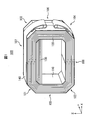
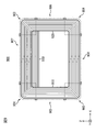
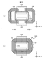
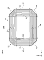
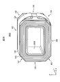
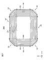
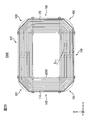
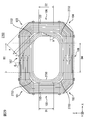
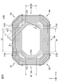
- FIG. 2 shows the first embodiment, and is a view of the wound iron core as viewed obliquely. It is the figure which showed 1st Embodiment and saw the winding core from the front.
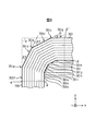
- FIG. 2 shows the first embodiment, and is an enlarged view showing the vicinity of a first corner portion. It is a figure which shows 1st Embodiment and shows an example of the bending part of a grain-oriented electrical steel sheet typically. It is a mimetic diagram showing a 1st embodiment and showing an example of a bending method.
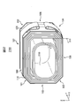
- FIG. 2 is a schematic diagram illustrating the first embodiment and illustrating an example of an assembling method. It is the figure which showed the 1st modification of 1st Embodiment and saw the winding core from the front.
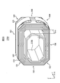
- FIG. 9 is a diagram illustrating a first modification of the first embodiment, and is an enlarged view of the vicinity of a first corner. It is the figure which showed the 2nd modification of 1st Embodiment, and saw the winding core from the front. It is a figure which shows the 2nd modification of 1st Embodiment, and expands and shows the 1st corner part vicinity. It is the figure which showed 2nd Embodiment and saw the winding core from diagonally. It is the figure which showed 3rd Embodiment and saw the winding core from diagonally. It is the figure which showed 3rd Embodiment and saw the winding core from the front. It is a mimetic diagram showing a 3rd embodiment and showing an example of an assembling method.
- FIG. 19 is a schematic view illustrating an example of an assembling method following FIG. 18. It is the figure which showed 5th Embodiment and saw the winding core from diagonally. It is the figure which showed 5th Embodiment and saw the winding core from the front. It is a mimetic diagram showing a 5th embodiment and showing an example of an assembling method.
- FIG. 23 is a schematic view illustrating an example of an assembling method following FIG. 22. It is the figure which showed the 1st modification of 5th Embodiment, and saw the winding core from the front. It is the figure which showed the 2nd modification of 5th Embodiment, and saw the winding core from the front. It is the figure which showed the 6th embodiment and looked at the winding iron core from diagonal. It is the figure which showed 6th Embodiment and saw the winding core from the front. It is the figure which showed the modification of 6th Embodiment, and looked at the wound iron core from the front. It is the figure which looked at the core 2700 of the 7th embodiment from the front.
- FIG. 9 is a schematic view showing another embodiment of the configuration shown in FIG.
- the length in the sheet width direction of the grain-oriented electrical steel sheet forming the third portion is set to be greater than the length in the sheet width direction of the grain-oriented electrical steel sheet forming the first portion and the second portion. It is a perspective view which shows the example which made long.
- the length in the sheet width direction of the grain-oriented electrical steel sheet forming the third part is set to the length in the sheet width direction of the grain-oriented electrical steel sheet forming the first part and the second part.
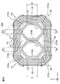
- FIG. 30 is a diagram of the wound core of the seventh embodiment as viewed from the front, and is a schematic diagram illustrating an example in which a third portion illustrated in FIG. 29 is divided into two.
- FIG. 35 is a schematic diagram showing an example in which the configuration shown in FIG. 34 is more generalized and the third portion is divided into n pieces.
- FIG. 35 is a schematic diagram showing an example in which, in the configuration example shown in FIG.
- FIG. 36 is a schematic diagram showing an example in which, in the configuration example shown in FIG. 35, similarly to the configuration example of FIG. 30, the outer shape of the third portion adjacent to the gap is linear.
- the XYZ coordinates indicate the relationship between the directions in each of the drawings, and the origin of the coordinates is not limited to the position shown in each of the drawings.
- a symbol with a cross in a circle indicates a direction from the near side to the far side of the paper surface.
- the terms “shape”, “along”, “vertical”, “perpendicular”, “same”, “identical” and the like for specifying shapes and geometric conditions and their degrees, for example.
- the values of the direction, the length, the angle, and the like are not limited to the strict meaning, and are interpreted to include a range in which a function equivalent to the described function can be expected. For example, if it is within the tolerance of the design, it can be treated as a range in which a function equivalent to the described function can be expected.
- FIG. 1 is an oblique view of the wound core 100.
- illustration of a winding (coil) installed on the wound core 100 is omitted for convenience of notation.
- the wound iron core 100 has a first portion 110, a second portion 120, and a third portion 130.
- a band 140 is attached to the outer peripheral surface of the wound core 100.
- a mounting bracket or the like for fixing the position of the wound core 100 is also attached to the band 140, but for convenience of notation, illustration of the mounting bracket and the like is omitted in FIG.
- the band 140 can be realized by a known technique, and is not limited to the one shown in FIG.
- FIG. 2 is a view of the wound iron core 100 as viewed from the front.
- the wound iron core 100 has four corner portions of a first corner portion 101, a second corner portion 102, a third corner portion 103, and a fourth corner portion 104.
- the first corner portion 101 and the second corner portion 102 are arranged with an interval in the Z-axis direction (first direction)
- the third corner portion 103 and the fourth corner portion 104 are also arranged in the Z-axis direction. They are arranged with an interval in the direction (first direction).
- first corner portion 101 and the third corner portion 103 are arranged with an interval in the X-axis direction (second direction), and the second corner portion 102 and the fourth corner portion 104 also They are arranged with an interval in the X-axis direction (second direction).
- the first portion 110 is a plurality of soft magnetic plates each having a shape bent at a position corresponding to the first corner portion 101 and the second corner portion 102 such that the plate surfaces overlap each other. It has a plurality of stacked soft magnetic plates.
- the second portion 120 is a plurality of soft magnetic plates each having a shape bent at a position corresponding to the third corner portion 103 and the fourth corner portion 104 so that the plate surfaces overlap each other. It has a plurality of stacked soft magnetic plates.
- the soft magnetic plate is, for example, a grain-oriented electrical steel plate.
- the direction (direction perpendicular to the sheet width direction and the sheet thickness direction) from the first corner portion 101 to the second corner portion 102 of the grain-oriented electrical steel sheet coincides with (is cut out as) the rolling direction.
- the soft magnetic material plate is a grain-oriented electromagnetic steel plate
- the thickness of the grain-oriented electrical steel sheet is not particularly limited and may be appropriately selected depending on the application and the like, but is usually in the range of 0.15 mm to 0.35 mm, and preferably 0.18 mm to 0 mm. .23 mm.
- the grain-oriented electrical steel sheets constituting the first portion 110 and the second portion 120 may be made of the same plate (having the same thickness, component, structure, etc.).
- a surface (end face) of one end (first end) in the longitudinal direction of the grain-oriented electrical steel sheet forming the first portion 110 and one end (longitudinal direction) of the grain-oriented electrical steel sheet forming the second part 120 ( The surface (end surface) of the first end is abutted on each other in the X-axis direction (second direction).
- the surface (end face) of the other end (second end) in the longitudinal direction of the grain-oriented electrical steel sheet constituting the first portion 110 and the longitudinal direction of the grain-oriented electrical steel sheet constituting the second portion 120 Are in a state where they face each other (the second end) in the X-axis direction (the second direction).
- the sheet surface of the grain-oriented electrical steel sheet constituting the first portion 110 and the sheet face of the grain-oriented electrical steel sheet constituting the second portion 120 overlap each other.
- the surface (end face) of the longitudinal direction of the grain-oriented electrical steel sheet constituting the first portion 110 and the face (end face) of the longitudinal direction end of the grain-oriented electrical steel sheet constituting the second portion 120 are matched in the X-axis direction (second direction). Further, as shown in FIGS.
- the surface (end face) of the longitudinal direction end of the grain-oriented electrical steel sheet forming the first portion 110 and the grain-oriented electrical steel sheet forming the second portion 120 The position in the circumferential direction of the wound iron core 100 at the position (joining portion) where the surface (end surface) of the end portion in the longitudinal direction abuts is a position periodically shifted in the X-axis direction (second direction). It has become. By doing so, the surface (end face) of the longitudinal direction of the grain-oriented electrical steel sheet constituting the first portion 110 and the longitudinal end of the grain-oriented electrical steel sheet constituting the second portion 120 are formed.
- a position (joining portion) where the surface (end face) abuts in the X-axis direction (second direction) is the same in the circumferential direction of the wound core 100 and the end faces are connected in the X-axis direction (second direction). ),
- the magnetic resistance in the wound iron core 100 can be reduced, and iron loss can be reduced.
- a region between the first corner portion 101 and the second corner portion 102 of the first portion 110 is a first rectangular parallelepiped portion 105 whose longitudinal direction is parallel to the Z axis.
- the region of the second portion 120 between the third corner portion 103 and the fourth corner portion 104 is also a second rectangular parallelepiped portion 106 whose longitudinal direction is parallel to the Z axis.
- a region between the first corner portion 101 and the third corner portion 103 of the first portion 110 and the second portion 120 is a third rectangular parallelepiped portion 107 whose longitudinal direction is parallel to the X axis.
- the region between the second corner portion 102 and the fourth corner portion 104 of the first portion 110 and the second portion 120 is also a fourth rectangular parallelepiped portion 108 whose longitudinal direction is parallel to the X axis. .
- Third portion 130 includes a plurality of grain-oriented electrical steel sheets stacked such that the plate faces overlap.
- the longitudinal direction of the grain-oriented electrical steel sheet (the direction perpendicular to the sheet width direction and the sheet thickness direction) is the same as the rolling direction.
- the plurality of grain-oriented electrical steel sheets constituting the third portion 130 of the present embodiment are flat plates (that is, X-axis directions) whose longitudinal directions are arranged in the X-axis direction. (That is, a flat plate extending in the direction) (that is, the surface of the grain-oriented electrical steel sheet is not bent).
- the third portion 130 is disposed in a window that is a region inside the first portion 110 and the second portion 120.
- one surface of the third portion 130 in the Z-axis direction (the surface of the directional electromagnetic steel plate located on the most positive side of the Z-axis among the directional electromagnetic steel plates forming the third portion 130) is , Among the inner peripheral surfaces of the first portion 110 and the second portion 120, are disposed at positions where they contact the inner peripheral surface between the first corner portion 101 and the third corner portion 103.
- the other surface of the portion 130 in the Z-axis direction (the surface of the grain-oriented electrical steel sheet located at the most negative side of the Z-axis among the grain-oriented electrical steel sheets forming the third part 130) is the third surface. It is not arranged at a position in contact with the inner peripheral surface between the corner 103 and the fourth corner 104.
- the length of the third portion 130 in the X-axis direction is the same as the length of the window portion in the X-axis direction at the position where the third portion 130 is disposed. That is, at least a part of one end (first end) in the longitudinal direction of the third part 130 is in contact with the inner peripheral surface of the first part 110, and the other end in the longitudinal direction of the third part 130. At least a part of the portion (second end) is in contact with the inner peripheral surface of the second portion 120.
- the thickness of the third portion 130 (the length in the thickness direction of the grain-oriented electrical steel sheet) is such that, when the band 140 is attached, the longitudinal end of the grain-oriented electrical steel sheet forming the first portion 110 and the second end portion of the The thickness of the first portion 110 (the second portion 120) (the thickness of the grain-oriented electrical steel sheet) in order to prevent the position of the grain-oriented electrical steel sheet forming the portion 120 from being shifted from the end in the longitudinal direction. It is preferably 0.001 times or more the length in the direction (original length of the leg of the wound core in the thickness direction).
- the number of grain-oriented electrical steel sheets does not always match the actual number of sheets for the sake of notation.
- the band 140 is attached (wrapped) to the outer peripheral surface of the wound core 100 including the first portion 110, the second portion 120, and the third portion 130 arranged as described above.
- the band 140 made of stainless steel is also provided with a metal fitting for the wound iron core 100, but for convenience of illustration, the metal fitting and the like are not shown in FIG.
- the core length of the wound core body is preferably 1.5 m or more, and more preferably 1.7 m or more.
- the core length of the wound core body refers to the laminating direction of the directional electromagnetic steel sheets of the wound core body when the wound core is viewed from the width direction (Y-axis direction) of the soft magnetic material plate (directional magnetic steel sheet). At the center point in the circumferential direction of the wound core. Further, since the wound core has reduced iron loss, it can be suitably used for any conventionally known applications such as a transformer, a reactor, and a magnetic core of a noise filter.
- the wound core body includes the corner portion (first corner portion 101 to fourth corner portion 104) and the rectangular parallelepiped portion (first rectangular parallelepiped portion 105 to fourth rectangular parallelepiped). Section 108) are present alternately and continuously.
- the first corner portion 101 ⁇ the first rectangular parallelepiped portion 105 ⁇ the second corner portion 102 ⁇ the fourth rectangular parallelepiped portion 108 ⁇ the fourth First corner portion 101 to fourth corner, such as corner portion 104 ⁇ second cuboid portion 106 ⁇ third corner portion 103 ⁇ third cuboid portion 107 ⁇ first corner portion 101 ⁇ .
- the portion 104 and the first to fourth rectangular parallelepiped portions 105 to 108 are arranged.
- first rectangular parallelepiped portion 105 to fourth rectangular parallelepiped portion 108 sandwiching each corner portion (first corner portion 101 to fourth corner portion 104) are interposed.
- the angle formed is 90 °.
- the angle between the first rectangular parallelepiped portion 105 and the fourth rectangular parallelepiped portion 108, the angle between the second rectangular parallelepiped portion 106 and the fourth rectangular parallelepiped portion 108, and the second rectangular parallelepiped The angle formed by the portion 106 and the third rectangular parallelepiped portion 107 and the angle formed by the first rectangular parallelepiped portion 105 and the third rectangular parallelepiped portion 107 are each 90 °.
- each of the corner portions (the first corner portion 101 to the fourth corner portion 104) has a curved shape. It has two bent portions, and the total of the bending angles of the bent portions existing in one corner portion is 90 °.
- FIG. 3 is an enlarged view showing the vicinity of the first corner portion 101.
- the shapes of the second corner portion 102, the third corner portion 103, and the fourth corner portion 104 are also the same as the shape of the first corner portion 101.
- the third corner 103 and the fourth corner 104 will not be described in detail.
- the bent portions 101a and 101b have a curved shape.
- a region between the bent portions 101a and 101b is a flat portion 101c.
- One corner portion is constituted by one or more bent portions. For this reason, the bent portion is continuous with the rectangular parallelepiped portion via the flat portion, and the flat portion and the bent portion follow the bent portion alternately and continuously according to the number of bent portions in one corner portion.
- a rectangular parallelepiped portion adjacent to the rectangular parallelepiped portion with the corner portion interposed therebetween is continuous with the last bent portion in the above via a flat portion.
- the bent portion 101a is continuous with the first rectangular parallelepiped portion 105 via the flat portion 101d, and the flat portion 101c and the bent portion 101b continue in this order following the bent portion 101a.
- the third rectangular parallelepiped portion 107 is continuous via the flat portion 101e. Note that the flat portions 101d and 101e may not be provided.
- a region from the line segment ⁇ - ⁇ ′ to the line segment ⁇ - ⁇ ′ is the first corner portion 101.
- the point ⁇ is an end point on the inner peripheral surface of the first corner portion 101 on the first rectangular parallelepiped portion 105 side.
- the point ⁇ ′ is a straight line passing through the point ⁇ in a direction perpendicular to the surface of the grain-oriented electrical steel sheet, and the wound core 1 00 (first portion 110) at the intersection with the outer peripheral surface.
- the point ⁇ is an end point on the inner peripheral surface of the first corner portion 101 on the side of the third rectangular parallelepiped portion 107, and the point ⁇ ′ is in a direction passing through the point ⁇ and perpendicular to the plate surface of the grain-oriented electrical steel sheet. This is the intersection between the straight line and the outer peripheral surface of the wound core 100 (first portion 110).
- the total of the bending angles ⁇ 1 and ⁇ 2 of the bent portions 101a and 101b in the first corner portion 101 (one corner portion) is 90 °.
- the bend angle of one bend ⁇ is less than 90 °.
- the bend angle ⁇ of one bend is 90 °.
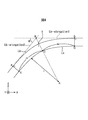
- FIG. 4 is a diagram schematically illustrating an example of a bent portion (curved portion) of a grain-oriented electrical steel sheet.
- the bending angle of the bent portion means an angle difference generated between the flat portion on the rear side and the flat portion on the front side in the bending direction in the bent portion of the grain-oriented electrical steel sheet.
- the bent portion of the grain-oriented electrical steel sheet is adjacent to both sides (points F and G) of the curved portion included in the line Lb representing the outer surface of the grain-oriented electrical steel sheet.
- the bending angle ⁇ of each bent portion is less than 90 °, and the sum of the bent angles of all the bent portions existing in one corner portion is 90 °.
- the bent portions are the points D and E on the line La representing the inner surface of the grain-oriented electrical steel sheet when the core is viewed from the width direction (Y-axis direction) of the grain-oriented electrical steel sheet.
- points F and G on a line Lb representing an outer surface of the grain-oriented electrical steel sheet are defined as follows
- points D and E on a line La representing the inner face of the grain-oriented electrical steel sheet are defined as follows.
- a line separated by points F and G on a line Lb representing the outer surface of the grain-oriented electrical steel sheet, a straight line connecting points D and E, and points F and G 2 shows an area surrounded by a straight line connecting.
- the points D, E, F and G are defined as follows. Straight lines adjacent to both sides of the center point A of the radius of curvature in the curved portion included in the line La representing the inner surface of the grain-oriented electrical steel sheet, and the curved portion included in the line Lb representing the outer surface of the grain-oriented electrical steel sheet.
- the origin C is defined as the point at which the straight line AB connecting the intersection B of the two virtual lines Lb-elongation1 and Lb-elongation2 obtained by extending the portion intersects with the line representing the inner surface of the grain-oriented electrical steel sheet.
- a point D is a point separated from the origin C by a distance m represented by the following equation (1) in one direction along a line La representing the inner surface of the grain-oriented electrical steel sheet.
- a point E is a point separated from the origin C by the distance m in another direction along a line La representing an inner surface of the grain-oriented electromagnetic steel sheet.
- the straight line portion facing the point D and the straight line portion facing the point D are drawn perpendicularly and pass through the point D.
- the point of intersection with the imaginary line is point G.
- the straight line portion facing the point E and the straight line portion facing the point E are drawn perpendicularly and pass through the point E.
- the point of intersection with the imaginary line is point F.
- r indicates the radius of curvature when the curve near the point C is regarded as a circular arc, and the directional electromagnetic steel sheet viewed from the width direction (Y-axis direction) of the directional electromagnetic steel sheet.
- the radius of curvature r of the bent portion can be in a range of more than 1 mm and less than 3 mm.
- the radius of curvature at each bent portion of each grain-oriented electromagnetic steel sheet laminated in the thickness direction may have a certain degree of error.
- the radius of curvature of each bent portion is specified as an average value of the radius of curvature of each laminated grain-oriented electrical steel sheet.
- the error is 0.1 mm or less.
- the method of measuring the radius of curvature of the bent portion is not particularly limited.
- the radius of curvature can be measured by observing with a commercially available microscope (Nikon ECLIPSE LV150) at a magnification of 200 times.
- the lengths of the grain-oriented electrical steel sheets forming the first portion 110 and the second portion 120 in the longitudinal direction and the plate width direction are determined according to the specifications of the wound core 100.
- the outer peripheral surface of the directional electromagnetic steel sheet disposed on the inner side and the inner peripheral surface of the directional electromagnetic steel sheet disposed on the outer side The lengths in the longitudinal direction and the plate width direction of each grain-oriented electrical steel sheet are determined so as to be equal. Then, the grain-oriented electrical steel sheet is cut in accordance with the determined length in the longitudinal direction and the length in the sheet width direction of the grain-oriented electrical steel sheet such that the longitudinal direction is the rolling direction.
- the surface (end face) of the longitudinal end portion of the directional electromagnetic steel sheet forming the first portion 110 and the directional electromagnetic steel forming the second portion 120 is in the X-axis direction (second direction). (Direction), the formation region of the corner portion, the position of the bent portion, and the bending angle in each grain-oriented electrical steel sheet are determined so as to be periodically shifted. In the examples shown in FIGS.
- bending processing is performed on two positions in the formation region of each corner of the grain-oriented electrical steel sheet, and a bent portion having a curvature radius r of more than 1 mm and less than 3 mm is formed.
- the rectangular parallelepiped portions (the first rectangular parallelepiped portion 105, the second rectangular parallelepiped portion 106, the third rectangular parallelepiped portion 107, and the fourth rectangular parallelepiped portion 108) and the corner portions (the first corner portion 101, the 2 corner portion 102, the third corner portion 103, and the fourth corner portion 104) are alternately continuous, and the angle ⁇ between two adjacent rectangular parallelepiped portions sandwiching each corner portion is 90 °.
- a grain-oriented electrical steel sheet is formed.
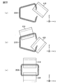
- FIG. 5 is a schematic diagram illustrating an example of a bending method in the method of manufacturing the wound iron core 100.
- the processing machine usually includes a die 502 and a punch 504 for press working and a grain-oriented electrical steel sheet 501. It has a guide 503 for fixing.
- the grain-oriented electrical steel sheet 501 is transported in the transport direction 505 and fixed at a preset position (FIG. 5B).
- the directional electromagnetic steel sheet is bent so as to have a bent portion with a bending angle ⁇ by pressing the punch 504 with a predetermined force set in advance in the direction of the arrow line (downward) shown in FIG. Processed.
- the method of setting the radius of curvature r of the bent portion to be more than 1 mm and less than 3 mm, but usually, the distance between the die 502 and the punch 504 and the shape of the die 502 and the punch 504 are changed. Thereby, the radius of curvature r of the bent portion can be adjusted to a specific range.
- the grain-oriented electrical steel sheet is processed by setting the radius of curvature r at the bent portion of each grain-oriented electrical steel sheet laminated in the thickness direction to be coincident with each other. An error may occur depending on the roughness or shape of the surface layer. Even if an error occurs, it is preferable that the error be 0.1 mm or less.
- the method of measuring the radius of curvature of the bent portion is not particularly limited.
- the radius of curvature can be measured by observing at a magnification of 200 using a commercially available microscope (Nikon ECLIPSE LV150).
- the distortion of the bent portion is removed by annealing.
- the sheet surfaces of the grain-oriented electrical steel sheets subjected to bending and strain relief annealing as described above overlap each other so that the first portion 110 and the second portion 120 are configured.
- Stacked conductive magnetic steel sheets Stacked conductive magnetic steel sheets.
- the grain-oriented electrical steel sheets forming the first portion 110 and the second portion 120 may be fixed so that the positions do not shift.
- the first portion 110 and the second portion 120 may be configured at the time of assembly described later.
- the length of the grain-oriented electrical steel sheet in the sheet width direction is the same as the length of the grain-oriented electrical steel sheet forming the first part 110 and the second part 120 in the sheet width direction, and the length in the longitudinal direction. Is the length in the X-axis direction of the window portion (the area inside the first portion 110 and the second portion 120), and the length in the X-axis direction at the position where the grain-oriented electrical steel sheet is arranged. Cut to be the same. At this time, the grain-oriented electrical steel sheet is cut so that the longitudinal direction is the rolling direction.
- the third portion 130 is configured so that the longitudinal end of each grain-oriented electrical steel sheet reliably contacts the inner peripheral surface of the first portion 110 and the inner peripheral surface of the second portion 120.
- the design minimum value of the length in the longitudinal direction of the grain-oriented electrical steel sheet is the length of the window portion (the area inside the first portion 110 and the second portion 120) in the X-axis direction, and The length in the X-axis direction at the position where the conductive magnetic steel sheet is arranged can be the same as the designed maximum value.
- the shape of the end in the longitudinal direction when viewed from the plate width direction (Y-axis direction) of the third portion 130 is the shape of the inner peripheral surface of the first corner portion 101 and the third corner portion 103.
- the cut grain-oriented electrical steel sheets are stacked with their plate surfaces overlapped so as to fit, and fixed so that the grain-oriented electrical steel sheets do not move.
- the fixation of the grain-oriented electrical steel sheet is realized by using, for example, an adhesive or the like.
- the adhesive is preferably magnetic.
- the end that comes into contact with the inner peripheral surface of the third corner portion 103 also has the inner peripheral surface of the first corner portion 101.
- the shape can be determined in the same manner as the contacting end.
- the shape of the end in the longitudinal direction of the grain-oriented electrical steel sheet when viewed from the sheet width direction (Y-axis direction) can be confirmed by, for example, observing with a commercially available microscope (Nikon ECLIPSE LV150) at a magnification of 200 times. Can be.
- the third portion 130 is prepared. After stacking and fixing directional magnetic steel sheets having the same shape and the same size, the shape of the end in the longitudinal direction matches the shape of the inner peripheral surfaces of the first corner portion 101 and the third corner portion 103. Thus, the grain-oriented electrical steel sheet may be processed. Further, the third portion 130 may be configured at the time of assembly described later.
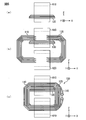
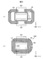
- FIG. 6 is a schematic view illustrating an example of an assembling method in the method of manufacturing the wound core 100.
- the third portion 130 is passed through the hollow portion of the coil 610.
- one end (first end) of the first portion 110 and one end (first end) of the second portion 120 are connected to a third end.
- Part 130 is located on the inner peripheral surface side of the first part 110 and the second part 120 (below the first part 110 and the second part 120 in FIG. 6B). Put in the hollow part of the coil 610.
- the other end (second end) of the first part 110 and the other end (second end) of the second part 120 are put into the hollow part of the coil 620.
- one plate surface of the third portion 130 (the upper surface of the third portion 130 in FIG. 6B) is connected to the first portion 110 and the second portion 120.
- the surface (end surface) of one end (first end) of the first portion 110 and the surface (end surface) of one end (first end) of the second portion 120 are in contact with the inner peripheral surface of the first portion 110. End in the X-axis direction (second direction), and the other end (second end) of the first portion 110 and the other end of the second portion 120.
- the surface (end surface) of the (second end) is abutted in the X-axis direction (second direction).
- the third portion 130 may or may not contact the inner peripheral surfaces of first portion 110 and second portion 120.
- a band 140 is attached to the outer peripheral surfaces of the first portion 110 and the second portion 120.
- the first part 110 and the second part 120 are tightened.
- the end surface (end face) of the outermost grain-oriented magnetic steel sheet is located in the X-axis direction (second direction).
- the compressive force concentrates on the butted part (joined part). Then, starting from this portion, the longitudinal end of the grain-oriented electrical steel sheet constituting the first portion 110 and the longitudinal end of the grain-oriented electrical steel sheet constituting the second portion 120 are aligned with the X-axis.
- the directional electromagnetic steel sheet constituting the first portion 110 enters a gap between the directional electromagnetic steel sheets constituting the second portion 120.
- the grain-oriented electrical steel sheet constituting the second portion 120 may enter a gap between the grain-oriented electrical steel sheets constituting the first portion 110.
- at the time of attaching the band 140 at least a part of the one end (first end) and at least a part of the other end (second end) of the third portion 130 in the longitudinal direction are respectively the The first portion 110 contacts the inner peripheral surface of the second portion 120. By doing so, it is possible to suppress the above-described penetration of the grain-oriented electrical steel sheet.
- the inner portion between the first corner portion 101 and the third corner portion 103 is formed in the area of the window, which is the area inside the first portion 110 and the second portion 120.
- the length of the window in the longitudinal direction (X-axis direction) is the same as the length in the X-axis direction of the window portion at the position where the third portion 130 is arranged so as to contact the region of the peripheral surface.
- the third part 130 is arranged. Therefore, when the band 140 is attached, the grain-oriented electrical steel sheet constituting the first part 110 enters between the grain-oriented electrical steel sheets constituting the second part 120 and the direction in which the second part 120 is formed. It is possible to prevent the directional magnetic steel sheet from entering between the directional magnetic steel sheets constituting the first portion 110.
- the longitudinal end of the grain-oriented electrical steel sheet forming the first part 110 and the longitudinal end of the grain-oriented electrical steel sheet constituting the second part 120 are in the X-axis direction (the second direction). ) Can be prevented from being shifted from a desired position (joined portion). Thereby, it is possible to prevent the wound core 100 from being deformed and becoming a desired shape, and from increasing iron loss.
- each corner portion when the wound iron core 100 is viewed from the sheet width direction (Y-axis direction) of the grain-oriented electrical steel sheet, each corner portion (first corner portion 101 to fourth corner portion 104) has a curved shape.
- the case where two bent portions having the above-mentioned shapes are provided has been described as an example.
- the number of bent portions included in each corner portion may be any number as long as it is one or more. In this case, it is preferable that the total of the bending angles of the bending portions existing at one corner is 90 °.
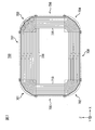
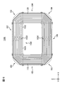
- FIG. 7 is a diagram of the wound iron core 700 viewed from the front.
- FIG. 7 is a diagram corresponding to FIG. 7, the wound core 700 has a first portion 710, a second portion 720, and a third portion 730.
- a band is attached to the outer peripheral surface of the wound core 700.
- FIG. 7 similarly to FIG. 2, illustration of a winding (coil) and a band installed on the wound core 700 is omitted for convenience of notation.
- the difference between the wound core 700 shown in FIG. 7 and the wound core 100 shown in FIGS. 1 to 3 is the shape of the corner portion and the shape of the longitudinal end of the third portion 730 .
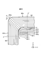
- FIG. 8 is an enlarged view showing the vicinity of the first corner portion 701.
- FIG. 8 is a diagram corresponding to FIG. Note that the shapes of the second corner portion 702, the third corner portion 703, and the fourth corner portion 704 are also the same as the shape of the first corner portion 701. , The third corner 703 and the fourth corner 704 will not be described in detail.
- the bent portions 701a, 701b, 701c have a curved shape.
- a region between the bent portions 701a and 701b and a region between the bent portions 701b and 701c are flat portions 701d and 701e, respectively.
- one corner portion is constituted by one or more bent portions.
- the bent portion is continuous with the rectangular parallelepiped portion via the flat portion, and the flat portion and the bent portion follow the bent portion alternately and continuously according to the number of bent portions in one corner portion.
- a rectangular parallelepiped portion adjacent to the rectangular parallelepiped portion with the corner portion interposed therebetween is continuous with the last bent portion in the above via a flat portion.
- the bent portion 701a is continuous with the first rectangular parallelepiped portion 705 via the flat portion 701f, and the flat portion 701d, the bent portion 701b, and the flat portion 701e continue in this order following the bent portion 701a.
- the third rectangular parallelepiped portion 707 is continuous with the bent portion 701c via the flat portion 701g. Note that the flat portions 701f and 701g may not be provided.
- a region from the line segment ⁇ - ⁇ ′ to the line segment ⁇ - ⁇ ′ is defined as a first corner portion 701.
- a point ⁇ is an end point on the inner peripheral surface of the first corner portion 701 on the first rectangular parallelepiped portion 705 side.
- the point ⁇ ′ is the intersection of the straight line passing through the point ⁇ and perpendicular to the plate surface of the grain-oriented electrical steel sheet and the outer peripheral surface of the wound core 700 (first portion 710).
- the point ⁇ is an end point on the inner peripheral surface of the first corner portion 101 on the side of the third rectangular parallelepiped portion 707, and the point ⁇ ′ is in a direction passing through the point ⁇ and perpendicular to the sheet surface of the grain-oriented electromagnetic steel sheet. This is an intersection between the straight line and the outer peripheral surface of the wound core 700 (first portion 710).
- the sum of the bending angles ⁇ 1, ⁇ 2, ⁇ 3 of the bent portions 701a, 701b, 701c in the first corner portion 701 (one corner portion) is 90 °.
- the third portion 730 is arranged in a window which is a region inside the first portion 710 and the second portion 720.
- the plate surface of the third portion 730 is formed on the inner peripheral surface between the first corner portion 701 and the third corner portion 703 among the inner peripheral surfaces of the first portion 710 and the second portion 720. It is arranged at the position where it touches.
- the length of the third portion 730 in the X-axis direction is the same as the length of the window portion in the X-axis direction at the position where the third portion 730 is arranged.
- At least a part of the surface (end surface) of one end (first end) in the longitudinal direction of the third portion 730 is in contact with the inner peripheral surface of the first portion 710, and At least a part of the surface (end surface) of the other end (second end) in the longitudinal direction is in contact with the inner peripheral surface of the second portion 720.
- the first By determining the positions of the points 701h to 701o such that the points 701h to 701o that come into contact with the inner peripheral surface of the corner 701 are located on a function representing the shape of the inner peripheral surface of the first corner 701,
- the shape of the end of the third portion 730 in the longitudinal direction when viewed from the plate width direction (Y-axis direction) can be adapted to the shape of the inner peripheral surface of the first corner portion 701.
- the end that comes into contact with the inner peripheral surface of the third corner portion 703 is also in contact with the inner peripheral surface of the first corner portion 701.
- the shape can be determined in the same manner as the contacting end.
- FIG. 9 is a front view of the wound core 900.
- FIG. 9 is a diagram corresponding to FIGS. 2 and 7.
- wound core 900 has first portion 910, second portion 920, and third portion 930.
- a band is attached to the outer peripheral surface of the wound core 900.
- FIG. 9 as in FIGS. 2 and 7, illustration of a winding (coil) and a band installed on the wound core 900 is omitted for convenience of notation.
- the difference between the wound iron core 900 shown in FIG. 9 and the wound iron core 100 shown in FIGS. 1 to 3 is the shape of the corner portion and the shape of the end of the third portion 930 in the longitudinal direction.
- FIG. 10 is an enlarged view showing the vicinity of the first corner portion 901.
- FIG. 10 is a diagram corresponding to FIGS. 3 and 8. Note that the shapes of the second corner portion 902, the third corner portion 903, and the fourth corner portion 904 are also the same as the shape of the first corner portion 901; , The third corner portion 903, and the fourth corner portion 904 are not described in detail.
- the bent portion 901a has a curved shape. As described above, one corner portion is constituted by one or more bent portions. For this reason, the bent portion is continuous with the rectangular parallelepiped portion via the flat portion, and the flat portion and the bent portion follow the bent portion alternately and continuously according to the number of bent portions in one corner portion.
- a rectangular parallelepiped portion adjacent to the rectangular parallelepiped portion with the corner portion interposed therebetween is continuous with the last bent portion in the above via a flat portion.
- a bent portion 901a is continuous with the first rectangular parallelepiped portion 905 via a flat portion 901b
- a third rectangular parallelepiped portion 907 is continuous with the bent portion 901a via a flat portion 901c. Note that the flat portions 901b and 901c may not be provided.
- a region from the line segment ⁇ - ⁇ ′ to the line segment ⁇ - ⁇ ′ is defined as a first corner portion 901.
- a point ⁇ is an end point on the inner peripheral surface of the first corner portion 901 on the first rectangular parallelepiped portion 905 side.
- the point ⁇ ′ is the intersection of the straight line passing through the point ⁇ and perpendicular to the sheet surface of the grain-oriented electrical steel sheet and the outer peripheral surface of the wound core 900 (first portion 910).
- a point ⁇ is an end point on the inner peripheral surface of the first corner portion 901 on the third rectangular parallelepiped portion 907 side
- a point ⁇ ′ is a point passing through the point ⁇ in a direction perpendicular to the plate surface of the grain-oriented electromagnetic steel sheet.
- Straight line and wound iron core 900 first (910) with the outer peripheral surface.
- the bending angle ⁇ of the bent part 901a in the first corner part 901 (one corner part) is 90 °.
- ⁇ 1 + ⁇ 2 +... + ⁇ n is 90 °.
- the third portion 930 is arranged in a window which is a region inside the first portion 910 and the second portion 920.
- the plate surface of the third portion 930 is formed on the inner peripheral surface between the first corner portion 901 and the third corner portion 903 among the inner peripheral surfaces of the first portion 910 and the second portion 920. It is arranged at the position where it touches.
- the length of the third portion 930 in the X-axis direction is the same as the length of the window portion in the X-axis direction at the position where the third portion 930 is arranged.
- the ninth portion 930 At least a part of the surface (end surface) of one end (first end) in the longitudinal direction is in contact with the inner peripheral surface of the first portion 910, and the ninth portion 930 At least a part of the surface (end surface) of the other end (second end) in the longitudinal direction is in contact with the inner peripheral surface of the second portion 920.
- the longitudinal ends of the directional electromagnetic steel sheets forming the third portion 930 By determining the positions of the respective points 701h to 701o such that the points 901d to 901k that come into contact with the inner peripheral surface of the corner portion 901 are located on a function representing the shape of the inner peripheral surface of the first corner portion 901.
- the shape of the end of the third portion 930 in the longitudinal direction when viewed from the plate width direction (Y-axis direction) can be adapted to the shape of the inner peripheral surface of the first corner portion 901.
- the end that comes into contact with the inner peripheral surface of the third corner portion 903 is also in contact with the inner peripheral surface of the first corner portion 901.
- the shape can be determined in the same manner as the contacting end.
- the third portions 130, 730, 930 are made of grain-oriented electrical steel sheets (soft magnetic plates) as in the present embodiment, the core loss of the wound iron cores 100, 700, 900 can be reduced. It is preferred. However, this is not necessary.
- the third portion may be a bulk portion having the same shape as the third portions 130, 730, and 930. Further, the third portion may be made of a nonmetallic material other than the soft magnetic material.
- the X-axis direction (second direction) of the longitudinal end of the grain-oriented electrical steel sheet constituting the first portion 110 and the longitudinal end of the grain-oriented electrical steel sheet constituting the second portion 120 is not limited to the band 140.
- a member that presses the first portion 110 from the negative direction of the X axis toward the positive direction of the X axis and a member that presses the second portion 120 from the positive direction of the X axis
- the first portion 110 and the second portion 120 may be sandwiched in the X-axis direction by using a member that presses the second portion 120 toward the negative direction.
- the plate surface of the third portion 130 is arranged at a position in contact with the inner peripheral surface between the first corner portion 101 and the third corner portion 103.
- a third portion where the plate surface contacts the inner peripheral surface between the second corner portion 102 and the fourth corner portion 104 is further arranged.
- the present embodiment is obtained by increasing the number of the third portions by one as compared with the first embodiment. Therefore, in the description of the present embodiment, the same portions as those in the first embodiment are denoted by the same reference numerals as those in FIGS. 1 to 10, and the detailed description is omitted.
- FIG. 11 is a diagram of the wound iron core 1100 viewed from the front.
- FIG. 11 is a diagram corresponding to FIG.
- a wound core 1100 has a first portion 110, a second portion 120, and third portions 130 and 1130.
- a band is attached to the outer peripheral surface of the wound core 100.
- FIG. 11 similarly to FIG. 2, illustration of a winding (coil) and a band installed on the wound core 100 is omitted for convenience of notation.
- the third part 1130 can be realized by the same thing as the third part 130.
- One surface of the third portion 130 in the Z-axis direction (the surface of the grain-oriented electrical steel sheet that is the most positively oriented in the Z-axis direction among the grain-oriented electrical steel sheets forming the third part 130) is the Of the inner peripheral surfaces of the first portion 110 and the second portion 120, the inner peripheral surface is disposed at a position in contact with the inner peripheral surface between the first corner portion 101 and the third corner portion 103.
- the other surface in the Z-axis direction of 130 is the third corner portion.
- one surface of the third portion 1130 in the Z-axis direction (the surface of the grain-oriented electrical steel sheet located at the most negative side of the Z-axis among the grain-oriented electrical steel sheets forming the third part 1130) ) Is disposed at a position in contact with the inner peripheral surface between the second corner portion 102 and the fourth corner portion 104 on the inner peripheral surface of the first portion 110 and the second portion 120.
- the other surface of the third portion 1130 in the Z-axis direction (the surface of the directional electromagnetic steel plate that is the most positive in the Z-axis direction among the directional electromagnetic steel plates forming the third portion 1130) is the third surface. It is not arranged at a position in contact with the inner peripheral surface between the first corner portion 101 and the second corner portion 102. Further, the third portions 130, 1130 are arranged with an interval in the Z-axis direction (first direction).
- the length of the third portion 1130 in the X-axis direction is equal to the length of the third portion 1130 of the window portion, which is an area inside the first portion 110 and the second portion 120.
- the length is the same as the length in the X-axis direction at the position where the portion 1130 is arranged. That is, at least a part of the surface (end surface) of one end (first end) in the longitudinal direction of the third portion 1130 is in contact with the inner peripheral surface of the first portion 110, and At least a part of the surface (end surface) of the other end (second end) in the longitudinal direction is in contact with the inner peripheral surface of the second portion 120.
- the inner portion between the first corner portion 101 and the third corner portion 103 is formed in the area of the window, which is the area inside the first portion 110 and the second portion 120.
- the length in the longitudinal direction (X-axis direction) of the window is set so that the plate surface contacts the region of the peripheral surface and the region of the inner peripheral surface between the second corner portion 102 and the fourth corner portion 104.
- the third portions 130, 1130 having the same length in the X-axis direction at positions where the third portions 130, 1130 of the portion are arranged are arranged, respectively.
- the third portions 130 and 1130 are located at positions corresponding to the two locations (joined portions) where the first portion 110 and the second portion 120 abut in the X-axis direction (second direction). Can be arranged. Therefore, when the band 140 is attached, the grain-oriented electrical steel sheet constituting the first part 110 enters between the grain-oriented electrical steel sheets constituting the second part 120, and the direction constituting the second part 120. It is possible to more reliably prevent the directional magnetic steel sheet from entering between the directional magnetic steel sheets constituting the first portion 110. Thereby, it is possible to more reliably prevent the wound iron core 100 from being deformed and becoming a desired shape, and from increasing iron loss. Also in the present embodiment, various modifications described in the first embodiment can be adopted. For example, the number of bent portions in one corner portion is not limited to two, and may be three or more or one. Further, third portion 1130 may not be formed of a grain-oriented electrical steel sheet (soft magnetic plate). Further, the band 140 need not be used.
- the plate surface of the third portion 130 is between the first corner portion 101 and the third corner portion 103 of the inner peripheral surfaces of the first portion 110 and the second portion 120.
- the case where the inner peripheral surface is contacted has been described as an example.
- the plate surface of the third portion does not come into contact with the inner peripheral surfaces of the first portion 110 and the second portion 120, and the end surface (end surface) in the longitudinal direction does not contact the plate surface.
- this embodiment mainly differs from the first embodiment in the configuration of the third portion. Therefore, in the description of the present embodiment, the same portions as those in the first embodiment are denoted by the same reference numerals as those in FIGS. 1 to 10, and the detailed description is omitted.
- FIG. 12 is an oblique view of the wound core 1200.
- FIG. 12 is a diagram corresponding to FIG. In FIG. 12, as in FIG. 1, illustration of a winding (coil) installed on the wound core 1200 is omitted for convenience of notation.
- wound core 1200 has first portion 110, second portion 120, and third portion 1230.
- a band 140 is attached to the outer peripheral surface of the wound core 1200.
- the band 140 is also provided with a mounting bracket for the wound iron core 1200, but in FIG. 12, as in FIG. 1, the mounting bracket and the like are not shown for convenience of notation.
- FIG. 13 is a diagram of the wound core 1200 as viewed from the front. In FIG. 13, as in FIG. 2, illustration of a winding (coil) and a band installed on the wound core 1200 is omitted for convenience of notation.
- Third portion 1230 has a plurality of grain-oriented electrical steel sheets stacked such that the plate faces overlap.
- the longitudinal direction of the grain-oriented electrical steel sheet (the direction perpendicular to the sheet width direction and the sheet thickness direction) is the same as the rolling direction.
- the plurality of grain-oriented electrical steel sheets constituting the third portion 1230 of the present embodiment are flat plates (that is, X-axis directions) whose longitudinal directions are arranged in the X-axis direction. (That is, a flat plate extending in the direction) (that is, the surface of the grain-oriented electrical steel sheet is not bent).
- the third portion 1230 is arranged in a window that is a region inside the first portion 110 and the second portion 120.
- the surface of the third portion 1230 in the Z-axis direction (the directionality located at the most positive Z-axis direction and the most negative Z-axis direction side of the grain-oriented electrical steel sheets forming the third portion 1230).
- the electromagnetic steel sheet does not contact the inner peripheral surfaces of the first portion 110 and the second portion 120.
- the length of the third portion 1230 in the X-axis direction is the same as the length of the window from the inner peripheral surface of the first rectangular parallelepiped portion 105 to the inner peripheral surface of the second rectangular parallelepiped portion 106. It is. Accordingly, the shape of the surface of the grain-oriented electrical steel sheet forming the third portion 1230 is all the same rectangular shape.
- At least a part (preferably all) of a surface (end surface) of one end (first end) in the longitudinal direction of the third portion 130 is formed on the inner periphery of the first portion 110 (first cuboid portion 105). At least a part (preferably all) of the surface (end face) of the other end (second end) in the longitudinal direction of the third portion 1230 is in contact with the second portion 120 (second rectangular parallelepiped). Contact the inner peripheral surface of the portion 106).
- the third portion 1230 is arranged at a position that avoids a space where the coils 610 and 620 are set at the time of assembling to be described later.
- the position of the center of the third portion 1230 in the thickness direction of the grain-oriented electrical steel sheet is set at an intermediate position between the inner peripheral surface of the third rectangular parallelepiped portion 107 and the inner peripheral surface of the fourth rectangular parallelepiped portion 108 ( That is, the third portion 1230 is arranged so as to be at the position (center position of the window portion in the Z-axis direction).
- the length of the grain-oriented electrical steel sheet in the sheet width direction is the same as the length of the grain-oriented electrical steel sheet forming the first portion 110 and the second portion 120 in the sheet width direction.
- the length in the longitudinal direction is the length in the X-axis direction of the window portion (the area inside the first portion 110 and the second portion 120), and the position where the directional electromagnetic steel sheet is arranged And cut into a rectangle so as to have the same length as in the X-axis direction.
- the shape and size of the grain-oriented electrical steel sheets forming the third portion 130 are the same.
- the directional electromagnetic steel sheets cut into a rectangular shape are stacked with their plate surfaces stacked one on another to form a rectangular parallelepiped, and each directional electromagnetic steel sheet is fixed so as not to move.
- the fixation of the grain-oriented electrical steel sheet is realized by using, for example, an adhesive or the like.
- the adhesive is preferably magnetic.
- the third portion 130 is prepared. Note that the third portion 1230 may be configured at the time of assembly described later.
- FIG. 14 is a schematic view illustrating an example of an assembling method in the method of manufacturing the wound core 1200.
- first portion 110 and one end (first end) of the second portion 120 are connected to the coil 610.
- the other end (second end) of the first portion 110 and the other end (second end) of the second portion 120 are put into the hollow portion of the coil 620 while being put into the hollow portion.
- the third portion 1230 is arranged between the coils 610 and 620.
- one end (first end) of the first portion 110 and one end (first end) of the second portion 120 are butted in the X-axis direction (second direction),
- the surface (end surface) of the other end (second end) of the first portion 110 and the surface (end surface) of the other end (second end) of the second portion 120 are aligned in the X-axis direction ( In the second direction).
- the surface (end face) of the end portion in the longitudinal direction of the third portion 1230 and the inner peripheral surface regions of the first portion 110 and the second portion 120 in the longitudinal direction of the third portion 1230 It is preferable to apply an adhesive to at least one of the end surface (the end surface) and a region in contact with the end surface. This is because the third portion 1230 can be securely fixed by the first portion 110 and the second portion 120.
- the adhesive is preferably magnetic.
- one end (first end) of the first portion 110 and one end (first end) of the second portion 120 are connected in the X-axis direction ( In the second direction) and the surface (end surface) of the other end (second end) of the first portion 110 and the other end (second end) of the second portion 120.
- the surface (end face) is abutted in the X-axis direction (second direction).
- the third portion 1230 is arranged so that the third portion 1230 is located at a predetermined position with a distance from the coils 610 and 620.
- the surface (end surface) of the third portion 1230 in the longitudinal direction is in contact with the inner peripheral surfaces of the first portion 110 and the second portion 120 when the band 140 described later is attached, this state is assumed. Then, the surface (end surface) of the longitudinal end of the third portion 1230 may or may not contact the inner peripheral surfaces of the first portion 110 and the second portion 120.
- a band 140 is attached to the outer peripheral surfaces of the first portion 110 and the second portion 120.
- the longitudinal end of the third portion 1230 contacts the inner peripheral surfaces of the first portion 110 and the second portion 120.
- the first portion 110 moves toward the second portion 120 (positive direction side of the X axis)
- the second portion 120 moves toward the first portion 110 (positive direction along the X axis). In the direction of the arrow).
- the third portion 1230 has its plate surface not in contact with the inner peripheral surfaces of the first portion 110 and the second portion 120, and has an end portion in the longitudinal direction. At least a part of the surface (end surface) is formed on the inner peripheral surface between the first corner portion 101 and the second corner portion 102 of the first portion 110 and the third corner portion of the second portion 120. It is arranged at a position in contact with the inner peripheral surface between 103 and fourth corner portion 104. Therefore, when the band 140 is attached, the grain-oriented electrical steel sheet constituting the first part 110 enters between the grain-oriented electrical steel sheets constituting the second part 120 and the direction in which the second part 120 is formed.
- the longitudinal end of the grain-oriented electrical steel sheet forming the first part 110 and the longitudinal end of the grain-oriented electrical steel sheet constituting the second part 120 are in the X-axis direction (the second direction). ) Can be prevented from being shifted from a desired position (joined portion). Thereby, it is possible to suppress that the wound core 1200 is deformed and does not have a desired shape, and that an iron loss increases.
- various modifications described in the first and second embodiments can be adopted.
- the number of bent portions in one corner portion is not limited to two, and may be three or more or one.
- third portion 1230 may not be formed of a grain-oriented electrical steel sheet (soft magnetic plate). Further, the band 140 need not be used.
- the third portions 130, 1130, and 1230 are formed by stacking flat grain-oriented electrical steel sheets (oriented electrical steel sheets whose sheet surfaces are not bent) so that the sheet surfaces overlap each other.
- the outer peripheral surface of the third portion matches the inner peripheral surfaces of the first portion 110 and the second portion 120.
- this embodiment mainly differs from the first to third embodiments in the configuration of the third portion. Therefore, in the description of the present embodiment, the same portions as those in the first to third embodiments are denoted by the same reference numerals as those in FIGS. 1 to 14, and the detailed description is omitted.
- FIG. 15 is a diagram of the wound core 1500 as viewed obliquely.
- FIG. 15 is a diagram corresponding to FIG.
- wound core 1500 has first portion 110, second portion 120, and third portion 1530.
- the band 140 is attached to the outer peripheral surface of the wound core 1500.
- the band 140 is also provided with a mounting bracket for the wound iron core 1500.
- FIG. 15 is a diagram of the wound core 1500 as viewed from the front. In FIG. 16, as in FIG. 2, illustration of a winding (coil) and a band installed on the wound core 1500 is omitted for convenience of notation.
- the first portion 110 and the second portion 120 are the same as those described in the first embodiment.
- the third portion 1530 has a first small portion 1531 and a second small portion 1532.
- the first small portion 1531 is a plurality of grain-oriented electrical steel sheets each having a shape bent at a position corresponding to the first corner portion 101 and the second corner portion 102, such that the plate surfaces overlap each other. And has a plurality of grain-oriented electrical steel sheets stacked in a stack.
- the second small portion 1532 is a plurality of directional electromagnetic steel sheets each having a shape bent at a position corresponding to the third corner portion 103 and the fourth corner portion 104 so that the plate surfaces overlap each other. And has a plurality of grain-oriented electrical steel sheets stacked in a stack.
- the longitudinal direction of the grain-oriented electrical steel sheet (the direction perpendicular to the sheet width direction and the sheet thickness direction) is the same as the rolling direction.
- the outer peripheral surface of the first small portion 1531 is configured to match the inner peripheral surface of the first portion 110. Further, the length in the width direction of the grain-oriented electrical steel sheet forming the first small portion 1531 is the same as the length in the width direction of the grain-oriented electrical steel sheet forming the first portion 110 and the second portion 120. It is. Similarly, the outer peripheral surface of the second small portion 1532 is configured to mate with the inner peripheral surface of the second portion 120. Further, the length in the sheet width direction of the grain-oriented electrical steel sheet constituting the second small portion 1532 is the same as the length in the sheet width direction of the grain-oriented electrical steel sheet constituting the first portion 110 and the second portion 120. It is.
- the other end (second end) in the longitudinal direction of the grain-oriented electrical steel sheet constituting the first small portion 1531 and the other end in the longitudinal direction of the grain-oriented electrical steel sheet constituting the second small portion 1532 are in a state where they abut each other in the X-axis direction (second direction).
- the position of the butted position 1534 in the circumferential direction of the wound core 1500 is the same in the X-axis direction (second direction).
- the longitudinal plate surface of the grain-oriented electrical steel sheet constituting the first small portion 1531 does not overlap with the longitudinal plate surface of the grain-oriented electrical steel sheet constituting the second small portion 1532, and
- the face (end face) of the longitudinal direction end of the grain-oriented electrical steel sheet constituting the first small portion 1531 and the face (end face) of the longitudinal direction end of the grain-oriented electrical steel sheet constituting the second small portion 1532 Are matched in the X-axis direction (second direction).
- the grain-oriented electrical steel sheets forming the third portion 1530 are located at positions corresponding to the first corner portion 101, the second corner portion 102, the third corner portion 103, and the fourth corner portion 104.
- the outer peripheral surface of the third portion 1530 is arranged in contact with the inner peripheral surfaces of the first portion 110 and the second portion.
- the surface (end surface) of the end portion of the grain-oriented electrical steel sheet forming third portion 1530 is located between first corner portion 101 and third corner portion 103.
- the position 1533 and the position 1534 between the second corner portion 102 and the fourth corner portion 104 are matched.
- the position 1533 is an intermediate position between the first corner portion 101 and the third corner portion 103, but the position 1533 is not necessarily the first corner portion 101 and the third corner portion. There is no need to be at an intermediate position between the parts 103.
- position 1534 need not be an intermediate position between second corner portion 102 and fourth corner portion 104.
- the first part 110, the second part 120, and the coils 610, 620 are the same as those described in the first embodiment.
- the third portion 1530 when the first small portion 1531 and the second small portion 1532 are combined, their outer peripheral surfaces are in contact with the inner peripheral surfaces of the first portion 110 and the second portion 120.
- the length in the longitudinal direction, the length in the sheet width direction, and the formation of the corner portion of the grain-oriented electrical steel sheet located at the outermost periphery The region, the position of the bent portion, and the bending angle, and the length in the longitudinal direction and the length in the plate width direction of the directional electromagnetic steel sheet located at the outermost periphery among the directional electromagnetic steel sheets forming the second small portion 1532 Then, the formation region of the corner portion, the position of the bent portion, and the bending angle are determined.
- two adjacent layers of the grain-oriented electrical steel sheet are formed on the inner side.
- the length in the longitudinal direction and the length in the width direction of each grain-oriented electrical steel sheet such that the outer peripheral surface of the grain-oriented electrical steel sheet to be arranged is equal to the inner peripheral surface of the grain-oriented electrical steel sheet placed outside.
- the corner forming area, the position of the bent portion, and the bending angle are determined.
- the grain-oriented electrical steel sheet is cut in accordance with the longitudinal direction length and the sheet width direction length of the grain-oriented electrical steel sheet determined as described above such that the longitudinal direction is the rolling direction. Then, the grain-oriented electrical steel sheet after cutting is subjected to bending according to the position and the bending angle of the bent portion determined as described above.
- the method of bending is the same as the method of bending the grain-oriented electrical steel sheets forming the first portion 110 and the second portion 120, and a detailed description thereof will be omitted.
- each grain-oriented electrical steel sheet laminated in the thickness direction is also provided.
- the radius of curvature r at the bent portion of the steel sheet coincides with the radius of curvature.
- an error may occur in the radius of curvature of the processed directional electromagnetic steel sheet depending on the roughness and shape of the steel sheet surface layer. Even if an error occurs, it is preferable that the error be 0.1 mm or less. Then, for each of the grain-oriented electrical steel sheets obtained by bending as described above, the distortion of the bent portion is removed by annealing.
- first and second small portions 1531 and 1532 are configured such that the plate surfaces of the grain-oriented electrical steel sheets subjected to bending and strain relief annealing as described above overlap each other. Stacked conductive magnetic steel sheets.
- the third portion 1530 (the first small portion 1531 and the second small portion 1532) is prepared.
- the grain-oriented electrical steel sheets constituting the first small portion 1510 and the second small portion 1532 may be fixed so as not to be displaced. Further, the first small portion 1510 and the second small portion 1532 may be configured at the time of assembly described later.
- FIG. 17 is a schematic view illustrating an example of an assembling method in the method of manufacturing the wound iron core 1500.
- the outer peripheral surface of the first small portion 1531 is fitted to the inner peripheral surface of the first portion 110
- the second small portion 1531 is fitted to the inner peripheral surface of the second portion 120.
- first end portion of the first portion 110 and the first small portion 1531 and one end portion (first end portion of the second portion 120 and the second small portion 1532 of the first portion 110 and the first small portion 1532) are brought into a state where the outer peripheral surfaces of the portion 1532 are fitted. (First end) into the hollow portion of the coil 610. At the same time, the other end (second end) of the first portion 110 and the first small portion 1531 and the other end (second end) of the second portion 120 and the second small portion 1532 ) Is inserted into the hollow portion of the coil 620.
- first end of the first portion 110 and the first small portion 1531 and one end (first end) of the second portion 120 and the second small portion 1532 are connected.
- the ends of the first portion 110 and the first small portion 1531 (the second end) and the second portion 120 and the second small portion are abutted in the X-axis direction (the second direction).
- the other end (second end) of the 1532 is abutted in the X-axis direction (second direction).
- a band 140 is attached to the outer peripheral surfaces of the first portion 110 and the second portion 120. When attaching the band 140, the first part 110 and the second part 120 are tightened.
- the third portion 1530 is formed by combining the first small portion 1531 and the second small portion 1532 so that the outer peripheral surface is formed by the first portion 110 and the second portion.
- An annular shape is formed so as to match with the inner peripheral surface of 120.
- the length of the third portion 1530 in the X-axis direction is such that the third portion 1530 is in contact with the region of the inner peripheral surface of the window, which is the region inside the first portion 110 and the second portion 120.
- the length of the window is the same as the length in the X-axis direction.
- the grain-oriented electrical steel sheet constituting the first part 110 enters between the grain-oriented electrical steel sheets constituting the second part 120 and the direction in which the second part 120 is formed. It is possible to prevent the directional magnetic steel sheet from entering between the directional magnetic steel sheets constituting the first portion 110. Therefore, the longitudinal end of the grain-oriented electrical steel sheet forming the first part 110 and the longitudinal end of the grain-oriented electrical steel sheet constituting the second part 120 are in the X-axis direction (the second direction). ) Can be prevented from being shifted from a desired position (joined portion). Thereby, it is possible to suppress that the wound core 1200 is deformed and does not have a desired shape, and that an iron loss increases.
- the side where the first portion 110 and the second portion 120 abut and the side where the first small portion 1531 and the second small portion 1532 abut can be the same. Therefore, the assembling work of the wound core 1500 is facilitated.
- the end face (end face) of the grain-oriented electrical steel sheet forming the third portion 1530 is located between the first corner portion 101 and the third corner portion 103 and between the second corner portion 102 and the fourth corner portion. It is only necessary that at least one of the corner portions 104 be abutted.
- the end face (end face) of the grain-oriented electrical steel sheet forming the third portion 1530 can be made to abut only between the first corner portion 101 and the third corner portion 103.
- FIG. 18 and FIG. 19 are schematic views showing an example of an assembling method in a method of manufacturing such a wound iron core 1800.
- a third portion 1830 is formed by connecting a first small portion 1531 and a second small portion 1532 at a position 1534 (that is, the third portion 1830 does not separate at a position 1534). ).
- the third portion 1830 is not divided into two smaller parts.
- a gap is formed at the longitudinal end of the grain-oriented electrical steel sheet forming the third portion 1830 by utilizing the elasticity of the grain-oriented electrical steel sheet.
- the third portion 1830 is passed through the hollow portion of the coil 620, and as shown in FIG. 18B, the coil 620 is moved to a region opposite to the region where the gap is located.
- the third portion 1830 is inserted into the hollow portion of the coil 610 with the above-mentioned gap formed. Then, as shown in FIG. 18C, one end (first end) and the other end (second end) of the third portion 1830 are connected in the X-axis direction (second end). In the state where the third portions 1830 are located in the hollow portion of the coil 610, the third portion 1830 is positioned at the longitudinal end.
- the outer peripheral surface of the third portion 1830 is fitted to the inner peripheral surface of the first portion 110, and the third portion 1830 is attached to the inner peripheral surface of the second portion 120. 1830. Then, one end (first end) of the first portion 110 and one end (first end) of the second portion 120 are put into the hollow portion of the coil 610. At the same time, the other end (second end) of the first part 110 and the other end (second end) of the second part 120 are put into the hollow part of the coil 620.
- one end (first end) of the first portion 110 and one end (first end) of the second portion 120 are combined, and The surface (end surface) of the other end (second end) of the first portion 110 is matched with the surface (end surface) of the other end (second end) of the second portion 120.
- a band 140 is attached to the outer peripheral surfaces of the first portion 110 and the second portion 120. When attaching the band 140, the first part 110 and the second part 120 are tightened.
- the end surfaces (end surfaces) of the grain-oriented electrical steel sheets forming the third portion 1830 abut on the same layer (the same stacking stage) in the X-axis direction (second direction). Position). Therefore, iron loss can be reduced as compared with the third portion 1530.
- one end (first end) of the first portion 110 and one end (first end) of the second portion 120 are connected.
- the other end (second end) of the first part 110 and the other end (second end) of the second part 120 are put in the hollow part of the coil 610.
- the third part 130 functions as a guide for positioning the first part 110 and the second part 120 in the Z-axis direction when the first part 110 and the second part 120 are combined.
- the wound core 1500 is viewed from the front, since the wound core 1500 is an octagonal square, the processing accuracy of the first portion 110, the second portion 120, and the third portion 1530 is increased. Therefore, the function of the third portion 130 as a guide is enhanced.
- the first portion 110 and the second portion 120 are combined, if the relative positions of the first portion 110 and the second portion 120 are shifted in the Z-axis direction, the first portion 110 is configured.
- the surface (end face) of the longitudinal direction end of the grain-oriented electrical steel sheet and the face (end face) of the longitudinal direction end of the grain-oriented electrical steel sheet forming the second portion 120 cannot be correctly aligned.
- the third portion 1830 forms the first portion 110 and the second portion 120 in the Z-axis direction. Functions as a guide for positioning. Therefore, when the first part 110 and the second part 120 are combined, the relative position of the first part 110 and the second part 120 is suppressed from being shifted in the Z-axis direction, and the first part 110 is suppressed.
- the surface (end face) of the longitudinal direction end of the grain-oriented electrical steel sheet constituting the portion 110 and the face (end face) of the longitudinal direction end of the grain-oriented electrical steel sheet constituting the second portion 120 are defined by the Z-axis. It can be adjusted to the correct position in the direction.
- the end faces of the grain-oriented electrical steel sheets forming the first portion 110 and the second portion 120 can be reliably brought into contact with each other.
- the 1531 and 1532 of the third portion 1830 are simultaneously combined. be able to.
- the number of steps of the assembling operation is smaller for the wound core 1500 than for the wound core 1800. Therefore, it is possible to determine which of the cores 1500 and 1800 to employ, depending on which of the reduction of iron loss and the burden of the assembling work is prioritized.
- the end surface (end surface) of the grain-oriented electrical steel sheet forming the third portion 1530 is in the X-axis direction (second direction) only between the second corner portion 102 and the fourth corner portion 104. May be matched. Further, also in the present embodiment, various modifications described in the first to third embodiments can be adopted. For example, the number of bent portions in one corner portion is not limited to two, and may be three or more or one. Further, the third portions 1530 and 1830 do not need to be formed of a grain-oriented electrical steel sheet (soft magnetic plate). Further, the band 140 need not be used.
- the surface (end surface) of the end portion of the grain-oriented electrical steel sheet forming the third portion is located between the first corner portion 101 and the third corner portion 103 and the second corner portion.
- the case where at least one between the second corner portion 102 and the fourth corner portion 104 is butted in the X-axis direction (second direction) has been described as an example.
- the end face (end face) of the grain-oriented electrical steel sheet forming the third portion is located between the first corner portion 101 and the second corner portion 102 and the third portion.
- this embodiment mainly differs from the first to fourth embodiments in the configuration of the third portion. Therefore, in the description of the present embodiment, the same portions as those in the first to fourth embodiments are denoted by the same reference numerals as those in FIGS. 1 to 19, and the detailed description is omitted.
- FIG. 20 is a diagram of the wound core 2000 viewed obliquely.
- FIG. 20 is a diagram corresponding to FIG. In FIG. 20, as in FIG. 1, illustration of a winding (coil) installed on the wound core 2000 is omitted for convenience of notation.
- wound core 2000 has first portion 110, second portion 120, and third portion 2030.
- a band 140 is attached to the outer peripheral surface of the wound core 2000.
- a mounting bracket for the wound iron core 2000 and the like are also attached to the band 140.
- FIG. 20 as in FIG.
- FIG. 21 is a view of the wound core 2000 as viewed from the front.
- illustration of a winding (coil) and a band installed on the wound core 2000 is omitted for convenience of notation.
- the first portion 110 and the second portion 120 are the same as those described in the first embodiment.
- the third portion 2030 has a plurality of shapes each bent at a position corresponding to the first corner portion 101, the second corner portion 102, the third corner portion 103, and the fourth corner portion 104. It is a grain-oriented electrical steel sheet, and has a plurality of grain-oriented electrical steel sheets stacked so that the sheet surfaces overlap each other.
- the longitudinal direction of the grain-oriented electrical steel sheet (the direction perpendicular to the sheet width direction and the sheet thickness direction) is the same as the rolling direction.
- the outer peripheral surface of the third portion 2030 is configured to be aligned with the inner peripheral surfaces of the first portion 110 and the second portion 120. Further, the length in the width direction of the grain-oriented electrical steel sheet forming the third portion 2030 is the same as the length in the width direction of the grain-oriented electrical steel sheet forming the first portion 110 and the second portion 120. is there.
- the surface (end surface) of one end (first end) and the surface (end surface) of the other end (second end) in the longitudinal direction of the grain-oriented electrical steel sheet forming the third portion 2030 are the second end. In the region between the third corner portion 103 and the fourth corner portion 104, they are butted in the Z-axis direction (first direction).
- the surface (end surface) of one end (first end) in the longitudinal direction of the grain-oriented electrical steel sheet forming the third portion 2030 and the other end (second end) The position in the circumferential direction of the wound iron core 100 at the position (joint portion) where the surface (end surface) of the core 100 abuts in the Z-axis direction (first direction) is in the Z-axis direction (first direction). It is out of position.
- the surface (end face) of the longitudinal direction of the grain-oriented electrical steel sheet constituting the first portion 110 and the face (end face) of the longitudinal direction of the grain-oriented electrical steel sheet constituting the second portion 120 are shifted in the X-axis direction (second direction) of the position (joint portion) in the X-axis direction (second direction) of the location (joint portion) in the X-axis direction (second direction).
- the surface (end surface) of one end (first end) and the surface (end surface) of the other end (second end) in the longitudinal direction of the grain-oriented electromagnetic steel sheet to be formed are in the Z-axis direction (first end). In the Z-axis direction (first direction), the position in the circumferential direction of the wound core 2000 of the portion (joined portion) that is joined in the Z direction is the same.
- the surface (end face) of the longitudinal direction of the grain-oriented electrical steel sheet constituting the first portion 110 and the longitudinal direction of the grain-oriented electrical steel sheet constituting the second portion 120 are formed.
- a position (joint portion) where the end surface (end surface) abuts in the X-axis direction (second direction) is a direction in which the circumferential position of the wound iron core 100 is shifted in the X-axis direction (second direction).
- the direction in which the circumferential position of the wound core 100 shifts in the X-axis direction (second direction) and the Z-axis direction (first direction) is, for example, as shown in FIG. When the wound core 2000 is viewed from the (Y-axis direction), this is an extension direction of an imaginary line connecting the centers in the thickness direction of the grain-oriented electromagnetic steel sheets constituting the joint for one cycle.
- the surface (end surface) of one end (first end) and the surface (end surface) of the other end (second end) in the longitudinal direction of the grain-oriented electromagnetic steel sheet to be formed are in the Z-axis direction (first end). In the Z-axis direction (first direction), the cycle of shifting the circumferential position of the wound core 100 at the position (joint portion) where the parts are joined in the (direction) is the same.
- the surface (end face) of the longitudinal direction of the grain-oriented electrical steel sheet forming the first portion 110 and the longitudinal direction of the grain-oriented electrical steel sheet forming the second portion 120 In the X-axis direction (second direction), the position in the circumferential direction of the wound core 100 at a position (joint portion) where the end surface (end surface) of the core 100 abuts in the X-axis direction (second direction) is 3 It is shifted periodically at the sheet cycle. Therefore, the surface (end surface) of one end (first end) and the surface (end surface) of the other end (second end) in the longitudinal direction of the grain-oriented electrical steel sheet forming the third portion 2030 are formed. Are also shifted periodically in the Z-axis direction (first direction) at three cycles in the circumferential direction of the wound iron core 100 at a position (joint portion) where they abut in the Z-axis direction (first direction).
- the first part 110, the second part 120, and the coils 610, 620 are the same as those described in the first embodiment.
- the outermost peripheral surface of the first portion 110 and the inner peripheral surface of the second portion 120 are the same as those of the grain-oriented electromagnetic steel sheets constituting the third portion 2030.
- the length in the longitudinal direction, the length in the plate width direction, the formation region of the corner portion, the position of the bent portion, and the bending angle of the directional electromagnetic steel sheet located on the outer periphery are determined.
- the surface (end surface) of one end (first end) in the longitudinal direction of the grain-oriented electrical steel sheet forming the third portion 2030 and the other end ( The position in the circumferential direction of the wound iron core 100 at the position (joint portion) where the surface (end surface) of the second end) abuts in the Z-axis direction (first direction) is in the Z-axis direction (first direction). ), The length in the longitudinal direction, the length in the width direction, the formation region of the corner portion, the position of the bent portion, and the bending angle of each grain-oriented electrical steel sheet are determined so as to periodically shift in (1).
- a surface (end surface) of one end (first end) and a surface (end surface) of the other end (second end) of the grain-oriented electrical steel sheet forming the third portion 2030 in the longitudinal direction are provided.
- the length in the longitudinal direction of each directional magnetic steel sheet such that the outer circumferential length of the directional magnetic steel sheet arranged on the inner side is equal to the inner circumferential length of the directional electromagnetic steel sheet arranged on the outer side.
- the length in the width direction of the plate, the formation region of the corner portion, the position of the bent portion, and the bending angle are determined.
- the grain-oriented electrical steel sheet is cut in accordance with the longitudinal direction length and the sheet width direction length of the grain-oriented electrical steel sheet determined as described above such that the longitudinal direction is the rolling direction. Then, the grain-oriented electrical steel sheet after cutting is subjected to bending according to the position and the bending angle of the bent portion determined as described above.
- the method of bending is the same as the method of bending the grain-oriented electrical steel sheets forming the first portion 110 and the second portion 120, and a detailed description thereof will be omitted.
- the third portion 2030 is also set so that the curvature radius r at the bent portion of each grain-oriented electromagnetic steel sheet laminated in the thickness direction matches.
- the radius of curvature of the processed grain-oriented electrical steel sheet may have an error depending on the roughness and shape of the steel sheet surface layer. Even if an error occurs, it is preferable that the error be 0.1 mm or less. Then, for each of the grain-oriented electrical steel sheets obtained by bending as described above, the distortion of the bent portion is removed by annealing.
- Each directional magnetic steel sheet is stacked so that the plate surfaces of the directional magnetic steel sheets that have been subjected to the bending process and the strain relief annealing as described above overlap each other so that the third portion 2030 is configured.
- the third part 2030 is prepared.
- the grain-oriented electrical steel sheets forming the third portion 2030 may be fixed so as not to be displaced.
- the third portion 2030 may be configured at the time of assembly to be described later.
- FIG. 22 and FIG. 23 are diagrams illustrating an example of an assembling method in a method of manufacturing such a wound iron core 3000.
- a gap is formed at the longitudinal end of the grain-oriented electrical steel sheet forming the third portion 2030 by utilizing the elasticity of the grain-oriented electrical steel sheet, and the third part 2030 is formed.
- the third part 2030 is formed.
- the third portion 2030 is passed through the hollow portion of the coil 620 with the above-described gap formed. Then, as shown in FIG. 22C, the third portion 2030 is positioned until the coil 620 is located on the portion of the two long sides of the third portion 2030 where the coil 610 is not disposed. Is moved, and one end (first end) of the third portion 1830 and the other end (second end) are abutted in the Z-axis direction (first direction).
- the inner peripheral surface of the first portion 110 is fitted with the outer peripheral surface of the third portion 2030, and the inner peripheral surface of the second portion 120 is fitted with the third portion. 2030. Then, one end (first end) of the first portion 110 and one end (first end) of the second portion 120 are put into the hollow portion of the coil 610. At the same time, the other end (second end) of the first part 110 and the other end (second end) of the second part 120 are put into the hollow part of the coil 620.
- one end (first end) of the first portion 110 and one end (first end) of the second portion 120 are connected in the X-axis direction ( In the second direction) and the surface (end surface) of the other end (second end) of the first portion 110 and the other end (second end) of the second portion 120. Abut on the surface (end surface) in the X-axis direction (second direction).
- a band 140 is attached to the outer peripheral surfaces of the first portion 110 and the second portion 120. When attaching the band 140, the first part 110 and the second part 120 are tightened.
- the end face (end face) of the grain-oriented electrical steel sheet forming the third portion 2030 is positioned between the third corner portion 103 and the fourth corner portion 104 in the Z-axis direction. (First direction). Further, the third portion 2030 is formed in an annular shape such that the outer peripheral surface thereof matches the inner peripheral surfaces of the first portion 110 and the second portion 120. For this reason, the length of the third portion 2030 in the X-axis direction is such that the third portion 2030 is in contact with the region of the inner peripheral surface of the window, which is the region inside the first portion 110 and the second portion 120. The length of the window is the same as the length in the X-axis direction.
- the grain-oriented electrical steel sheet constituting the first part 110 enters between the grain-oriented electrical steel sheets constituting the second part 120 and the direction in which the second part 120 is formed. It is possible to prevent the directional magnetic steel sheet from entering between the directional magnetic steel sheets constituting the first portion 110. Therefore, the longitudinal end of the grain-oriented electrical steel sheet forming the first part 110 and the longitudinal end of the grain-oriented electrical steel sheet constituting the second part 120 are in the X-axis direction (the second direction). ) Can be prevented from being shifted from a desired position (joined portion). Thereby, it is possible to suppress that the wound core 2000 is deformed and does not have a desired shape, and that an iron loss increases.
- one end (first end) of the first portion 110 and one end (first end) of the second portion 120 are connected.
- the other end (second end) of the first part 110 and the other end (second end) of the second part 120 are put in the hollow part of the coil 610.
- the outer peripheral surface of the third portion 2030 in the Z-axis direction comes into contact with the inner peripheral surfaces of the first portion 110 and the second portion 120 in the Z-axis direction. Therefore, the third part 2030 functions as a guide for positioning the first part 110 and the second part 120 in the Z-axis direction when the first part 110 and the second part 120 are combined.
- the first portion 110 and the second portion 120 are combined, if the relative positions of the first portion 110 and the second portion 120 are shifted in the Z-axis direction, the first portion 110 is configured.
- the surface (end face) of the longitudinal direction end of the grain-oriented electrical steel sheet and the face (end face) of the longitudinal direction end of the grain-oriented electrical steel sheet forming the second portion 120 cannot be correctly aligned.
- the third part 2030 is a guide for positioning the first part 110 and the second part 120 in the Z-axis direction when the first part 110 and the second part 120 are aligned. Function as Therefore, when the first part 110 and the second part 120 are combined, the relative position of the first part 110 and the second part 120 is suppressed from being shifted in the Z-axis direction, and the first part 110 is suppressed.
- the surface (end face) of the longitudinal direction end of the grain-oriented electrical steel sheet constituting the portion 110 and the face (end face) of the longitudinal direction end of the grain-oriented electrical steel sheet constituting the second portion 120 are defined by the Z-axis. It can be adjusted to the correct position in the direction. Therefore, the end faces of the grain-oriented electrical steel sheets forming the first portion 110 and the second portion 120 can be reliably brought into contact with each other.
- the surface (end surface) of one end (first end) and the other end (second end) of the grain-oriented electrical steel sheet forming the third portion 2030 in the longitudinal direction are arranged.
- the position (joint portion) where the surface (end face) abuts in the Z-axis direction (first direction) is shifted in the circumferential direction of the wound core 2000 in the Z-axis direction (first direction). Accordingly, iron loss can be reduced as compared with a case where the position of the portion in the circumferential direction of the wound core 2000 is not shifted in the Z-axis direction (first direction).
- the end surface (end surface) of the grain-oriented electrical steel sheet forming the third portion 2030 is positioned between the third corner portion 103 and the fourth corner portion 104 in the Z-axis direction (first surface). Direction).
- the end face (end face) of the grain-oriented electrical steel sheet forming the third portion 2430 is between the first corner portion 101 and the second corner portion 102.
- the end surface (end surface) of the grain-oriented electrical steel sheet forming the third portion 2530 is between the first corner portion 101 and the second corner portion 102.
- the third portion 2530 has a first small portion 2531 and a second small portion 2532.
- the first small portion 2531 is located between the first corner portion 101 and the third corner portion 2530 more than the portion where the end surface (end surface) of the grain-oriented electrical steel sheet forming the third portion 2530 abuts.
- a region on the third corner portion 103 side (positive direction side of the Z axis) is configured.
- the second small portion 2532 is larger than the portion of the third portion 2530 where the end surface (end surface) of the grain-oriented electrical steel sheet forming the third portion 2530 is abutted, and A region on the fourth corner 104 side (the negative direction side of the Z axis) is configured.
- the portions where the end surfaces (end surfaces) of the grain-oriented electrical steel sheets forming the third portions 2030 and 2430 abut in the Z-axis direction (first direction) are the same layer.
- the case where there is only one position in (1) is such that the end surface (end surface) of the grain-oriented electrical steel sheet forming the third portions 2030 and 2530 is in the Z-axis direction (first direction).
- Iron loss can be reduced as compared with a case where two butted portions are in the same layer.
- the winding core 2500 is easier to assemble than the cores 2000 and 2400. Therefore, it is possible to determine which of the cores 2000, 2400, and 2500 to employ, based on which of the iron loss reduction and the burden of the assembly work is prioritized.
- the circumferential position of the end face (end face) of the grain-oriented electrical steel sheet forming third portion 2030 is shifted in the Z-axis direction (first direction), iron loss can be reduced. preferable.
- the circumferential position of the end face (end face) of the grain-oriented electrical steel sheet forming third portion 2030 may be the same in the Z-axis direction (first direction).
- various modifications described in the first to fourth embodiments can be adopted.
- the number of bent portions in one corner portion is not limited to two, and may be three or more or one.
- third portions 2030, 2430, and 2530 do not have to be formed of grain-oriented electrical steel sheets (soft magnetic plates). Further, the band 140 need not be used.
- the length of the grain-oriented electrical steel sheet forming the third portion in the sheet width direction is the length of the grain-oriented electrical steel sheet forming the first portion 110 and the second portion 120 in the sheet width direction. And the same as On the other hand, the length of the grain-oriented electrical steel sheet constituting the third portion in the sheet width direction is longer than the length of the grain-oriented electrical steel sheet constituting the first portion 110 and the second portion 120 in the sheet width direction. Good. According to such a configuration, since the length of the third portion in the plate width direction is longer, for example, in the process shown in FIGS. When the first portion 110 and the second portion 120, which are made of steel plates bent from, are overlapped, the third portion serving as a guide is easily seen. Therefore, the positions of the first part and the second part can be easily determined, The work at the time of assembling the winding core 2000 becomes efficient.
- FIG. 31 is a diagram illustrating a directional electromagnetic steel sheet forming the first part 110 and the second part 120 according to the fifth embodiment. It is a perspective view which shows the example made longer than the length of the board width direction of FIG.
- FIG. 31 corresponds to FIG. In FIG. 31, the length in the width direction of the grain-oriented electrical steel sheet forming the third portion 2030 is longer than that in FIG. 20. Specifically, the third portion 2030 protrudes forward by a distance D10 in the plate width direction from the first portion 110 and the second portion 120. Similarly, the third portion 2030 protrudes further behind the first portion 110 and the second portion 120 by a distance D10 in the plate width direction than the back side of the wound core shown in FIG.
- the surface (end surface) of the end portion of the grain-oriented electrical steel sheet forming the third portion is between the first corner portion 101 and the third corner portion 103 and between the second corner portion 102 and the second corner portion 102.
- a case in which only one of the fourth corner portions 104 is butted in the X-axis direction (second direction) will be described.
- this embodiment mainly differs from the first to fifth embodiments in the configuration of the third portion. Therefore, in the description of the present embodiment, the same portions as those in the first to fifth embodiments are denoted by the same reference numerals as in FIGS. 1 to 25, and the detailed description is omitted.
- FIG. 26 is a diagram of the wound iron core 2600 viewed obliquely.
- FIG. 26 is a diagram corresponding to FIG. In FIG. 26, as in FIG. 1, illustration of a winding (coil) installed on the wound core 2600 is omitted for convenience of notation.
- the wound core 2600 has a first portion 110, a second portion 120, and a third portion 2630.
- Band 140 is attached to the outer peripheral surface of wound iron core 2600.
- the band 140 is also provided with a metal fitting for the wound iron core 2600.
- FIG. 20 as in FIG.
- FIG. 27 is a diagram of the wound iron core 2600 viewed from the front.
- illustration of a winding (coil) and a band installed on the wound core 2600 is omitted for convenience of notation.
- the first portion 110 and the second portion 120 are the same as those described in the first embodiment.
- the third portion 2630 includes the third portion 2030 described in the fifth embodiment and a surface (one end (first end)) in the longitudinal direction of the grain-oriented electrical steel sheet forming the third portion 2630 (the first end). The only difference is the position of the part (joining part) where the end face) and the surface (end face) of the other end part (second end part) abut against each other.
- the surface (end surface) of one end (first end) in the longitudinal direction of the grain-oriented electrical steel sheet forming the third portion 2030 and the other end is abutted in the Z-axis direction (first direction) in a region between the third corner portion 103 and the fourth corner portion 104.
- the surface (end surface) of one end (first end) in the longitudinal direction of the grain-oriented electrical steel sheet forming the third portion 2630 and the other end ( The surface (end surface) of the second end) is abutted in the X-axis direction (second direction) in a region between the first corner portion 101 and the third corner portion 103.
- the surface (end surface) of one end (first end) and the surface (end surface) of the other end (second end) in the longitudinal direction of the grain-oriented magnetic steel sheet to be formed are in the X-axis direction (second end).
- the position in the circumferential direction of the wound iron core 2600 (the second direction) at the position where the butted portions (joint portions) are joined in the same direction) is the same.
- a longitudinal end portion of the grain-oriented electrical steel sheet forming the first portion 110 in a region between the first corner portion 101 and the third corner portion 103, a longitudinal end portion of the grain-oriented electrical steel sheet forming the first portion 110. (End face) and the face (end face) of the longitudinal end of the grain-oriented electrical steel sheet forming the second portion 120 in the X-axis direction (second direction).
- the shape of one end (first end) and the other end (second end) of the third portion 1830 described in the fourth embodiment Prepare the third portion 2630 so that the shape of the third portion 2030 described in the fifth embodiment is the shape of one end (first end) and the other end (second end). I do. Then, as described with reference to FIGS. 18 and 19, the first portion 110, the second portion 120, and the third portion 2630 are combined to form the outer periphery of the first portion 110 and the second portion 120. Attach band 140 to the surface.
- the method of manufacturing the core 2600 of the present embodiment is realized by referring to the method of manufacturing the core 1800 described in the fourth embodiment and the core 2000 described in the fifth embodiment. Therefore, a detailed description thereof is omitted here.
- the end surface (end surface) of the grain-oriented electrical steel sheet forming the third portion 2630 is in the X-axis direction between the first corner portion 101 and the third corner portion 103. (The second direction).
- the surface (end surface) of one end (first end) and the surface (end surface) of the other end (second end) of the grain-oriented electrical steel sheet forming the third portion 2630 in the longitudinal direction are provided. Is shifted in the X-axis direction (second direction) in the circumferential direction of the wound core 2600 at a position (joining portion) where the two meet in the X-axis direction (second direction).
- third portion 2630 is formed in a ring shape such that the outer peripheral surface thereof matches the inner peripheral surfaces of first portion 110 and second portion 120.
- the length of the third portion 2630 in the X-axis direction is such that the third portion 2630 is in contact with the region of the inner peripheral surface of the window, which is the region inside the first portion 110 and the second portion 120.
- the length of the window is the same as the length in the X-axis direction. Therefore, when the band 140 is attached, the grain-oriented electrical steel sheet constituting the first part 110 enters between the grain-oriented electrical steel sheets constituting the second part 120 and the direction in which the second part 120 is formed. It is possible to prevent the directional magnetic steel sheet from entering between the directional magnetic steel sheets constituting the first portion 110.
- the longitudinal end of the grain-oriented electrical steel sheet forming the first part 110 and the longitudinal end of the grain-oriented electrical steel sheet constituting the second part 120 are in the X-axis direction (the second direction). ) Can be prevented from being shifted from a desired position (joined portion). Thereby, it is possible to prevent the wound iron core 2600 from being deformed and becoming a desired shape, and from increasing iron loss. In addition, iron loss can be reduced as compared with the wound iron core 1800 (third portion 1830) described in the fourth embodiment.
- the third portion 2630 moves in the Z-axis direction. It functions as a guide for positioning the first part 110 and the second part 120. Therefore, when the first part 110 and the second part 120 are combined, the relative position of the first part 110 and the second part 120 is suppressed from being shifted in the Z-axis direction, and the first part 110 is suppressed. Correctly align the longitudinal end surface (end surface) of the grain-oriented electrical steel sheet forming the portion 110 with the longitudinal edge surface (end face) of the grain-oriented electrical steel sheet constituting the second portion 120 Can be. Therefore, the end faces of the first portion 110 and the second portion 120 can be reliably brought into contact with each other.
- the end face (end face) of the grain-oriented electrical steel sheet forming the third portion 2630 is positioned between the first corner portion 101 and the third corner portion 103 in the X-axis direction (second direction). Direction).
- the end surface (end surface) of the grain-oriented electrical steel sheet forming the third portion 2830 is between the second corner portion 102 and the fourth corner portion 104. May be matched in the X-axis direction (second direction).
- various modifications described in the first to fifth embodiments can be adopted.
- the number of bent portions in one corner portion is not limited to two, and may be three or more or one.
- third portions 2630 and 2830 need not be formed of grain-oriented electrical steel sheets (soft magnetic plates). Further, the band 140 need not be used.
- each of the first corner portion 101, the second corner portion 102, the third corner portion 103, and the fourth corner portion 104 performs It relates to a configuration in which a gap is provided between the third portion 2730 and the first portion 110 or the second portion 120.
- FIG. 29 is a front view of a wound core 2700 according to the seventh embodiment.
- illustration of a winding (coil) and a band installed on the wound iron core 2700 is omitted for convenience of notation.
- the first portion 110 and the second portion 120 are the same as those described in the first embodiment.
- the third portion 2730 includes a plurality of bent portions each having a shape corresponding to the first corner portion 101, the second corner portion 102, the third corner portion 103, and the fourth corner portion 104. It is a grain-oriented electrical steel sheet, and has a plurality of grain-oriented electrical steel sheets stacked so that the sheet surfaces overlap each other.
- the longitudinal direction of the grain-oriented electrical steel sheet (the direction perpendicular to the sheet width direction and the sheet thickness direction) is the same as the rolling direction.
- the outer peripheral surface of the third portion 2730 is configured to fit with the inner peripheral surfaces of the first portion 110 and the second portion 120.
- the third portion 2730 is not in contact with the first portion and the second portion 120 over the entire outer peripheral surface, but is in contact with the third portion 2730.
- a gap 2732 is provided between the first portion 110 and the second portion 120.
- a gap 2732 is provided between the first portion 110 and the second portion 120.
- a gap 2732 is provided between the third portion 2730 and the first portion 110 or the second portion 120.
- the third portion 2730 is formed in an annular shape such that a part of the outer peripheral surface matches the inner peripheral surfaces of the first portion 110 and the second portion 120.
- the region D1 shown in FIG. 29 contacts the first portion 110
- the region D2 contacts the second portion 120.
- the region D3 shown in FIG. 29 contacts the first portion 110 and the second portion 120
- the region D4 corresponds to the first portion. Abuts 110 and second portion 120.
- the length of the third portion 2730 in the X-axis direction is set so that the third portion 2730 contacts the region of the inner peripheral surface of the window, which is the region inside the first portion 110 and the second portion 120. , The length of the window in the X-axis direction. Therefore, when the band 140 is attached, the grain-oriented electrical steel sheet constituting the first part 110 enters between the grain-oriented electrical steel sheets constituting the second part 120 and the direction in which the second part 120 is formed. It is possible to prevent the directional magnetic steel sheet from entering between the directional magnetic steel sheets constituting the first portion 110.
- the longitudinal end of the grain-oriented electrical steel sheet forming the first part 110 and the longitudinal end of the grain-oriented electrical steel sheet constituting the second part 120 are in the X-axis direction (the second direction). ) Can be prevented from being shifted from a desired position (joined portion). Thereby, it is possible to prevent the wound iron core 2700 from being deformed and becoming a desired shape, and from increasing iron loss.
- the third portion 2730 is the first portion in the Z-axis direction. It functions as a guide for positioning the portion 110 and the second portion 120. Therefore, when the first part 110 and the second part 120 are combined, the relative position of the first part 110 and the second part 120 is suppressed from being shifted in the Z-axis direction, and the first part 110 is suppressed. Correctly align the longitudinal end surface (end surface) of the grain-oriented electrical steel sheet forming the portion 110 with the longitudinal edge surface (end face) of the grain-oriented electrical steel sheet constituting the second portion 120 Can be. Therefore, the end faces of the first portion 110 and the second portion 120 can be reliably brought into contact with each other.
- the bent portion is provided at the first corner portion 101, the second corner portion 102, the third corner portion 103, and the fourth corner portion 104. Therefore, the temperature of these corner portions and the peripheral portions thereof is likely to increase.
- the third portion 2730 and the first portion 110 or A gap 2732 is provided between the second portion 120 and the second portion 120. Therefore, the heat generated at the bent portions of the corners is radiated to the gap 2732.
- the heat generated by the iron loss at the bent portion is radiated from the gap 2732, thereby suppressing the temperature rise of the wound core 2700.
- the thickness of the second portion 120 (or the first portion 110) is a
- the width of the gap 2732 is b
- the thickness of the third portion 2730 Assuming that c, the relationship of a> c is established.
- the iron loss at the bent portion of the wound core 2700 is larger inside the wound core 2700. For this reason, heat is generated due to iron loss at the bent portion toward the inside of the wound core 2700. Therefore, by making the thickness c of the third portion 2730 smaller than the thickness a of the first portion 110 (or the second portion 120), the inner portion of the wound core 2700 is caused by iron loss of the bent portion. Heat can be suppressed.
- the width b of the gap 2732 is equal to or less than the sum of the thickness a of the first portion 110 (or the second portion 120) and the thickness c of the third portion 2730.
- the width b of the gap 2732 is preferably equal to or less than the sum of the thickness a of the first portion 110 (or the second portion 120) and the thickness c of the third portion 2730.
- b ⁇ (a + c) / 285 the heat generated by the core loss at the bent portion cannot be radiated from the gap 2732. Therefore, it is preferable that b ⁇ (a + c) / 285.
- the thickness of the grain-oriented electromagnetic steel sheets forming the first portion 110 (or the second portion 120) and the third portion 2730 is 0.3 mm, and when the winding thickness (a + c) is 100 mm, 0 A gap 2732 with a width b of .35 mm or more is guaranteed.
- the thickness of the grain-oriented electrical steel sheet forming the first portion 110 (or the second portion 120) and the third portion 2730 is t, b> t, that is, the width b of the gap 2732 Is desirably larger than the thickness t of the grain-oriented electrical steel sheet.
- the gap 2732 not only the effect of dissipating the heat generated in the wound core 2700 but also the suppression of a rise in the oil temperature of the transformer is achieved. That is, by providing the gap 2732, a gap through which the cooling medium is passed is formed near the winding (coil), so that not only heat radiation generated by the wound core 2700 but also heat generated by the coil of the transformer is generated. As a result, a great effect can be obtained also in the heat radiation of the substrate.
- the thickness of the second portion 120 is a and the thickness of the third portion 2730 is c
- the relationship a> c is established. That is, the thickness of the second portion 120 (or the first portion 110) is greater than the thickness of the third portion 2730.
- the thickness of the third portion 2730 may be thicker than the thickness of the second portion 120 (or the first portion 110). That is, a ⁇ c may be satisfied.
- the shape of the outer peripheral surface of the third portion and the shape of the inner peripheral surface of the first portion 110 or the second portion 120 are required to match.
- the shape of the outer peripheral surface of the third portion and the first portion 110 Alternatively, if the shape of the inner circumferential surface of the second portion 120 does not match, the outer circumferential surface of the third portion contacts the inner circumferential surface of the first portion 110 or the second portion 120 over the entire circumference.
- the shape of the outer peripheral surface of the third portion and the first portion 110 May not. Therefore, in particular, in the first corner portion 101, the second corner portion 102, the third corner portion 103, and the fourth corner portion 104, the shape of the outer peripheral surface of the third portion and the first portion 110 Alternatively, a certain degree of accuracy is required for the shape of the inner peripheral surface of the second portion 120.
- each of the first corner portion 101, the second corner portion 102, the third corner portion 103, and the fourth corner portion 104 has the third portion 2730 Since a gap is provided between the first portion 110 and the second portion 120, the shape of the outer peripheral surface of the third portion and the shape of the first portion 110 or the second portion 120 Accuracy is not required for the shape of the inner peripheral surface.
- the seventh embodiment if the accuracy of the length of the third portion 2730 is obtained in the X-axis direction and the Z-axis direction, the first corner portion 101 and the second corner portion In each of 102, third corner 103, and fourth corner 104, the accuracy of the shape of the outer peripheral surface of third portion 2730 is not required. Even in that case, when the band 140 is attached, the grain-oriented electrical steel sheet constituting the first portion 110 enters between the grain-oriented electrical steel sheets constituting the second portion 120, and the second portion It is suppressed that the grain-oriented electrical steel sheets constituting the first portion 120 enter between the grain-oriented electrical steel sheets constituting the first portion 110. Further, when the first part 110 and the second part 120 are combined, the relative position of the first part 110 and the second part 120 is suppressed from being shifted in the Z-axis direction.
- the dimensional accuracy of the outer peripheral surface of the third portion 2730 is not required.
- the manufacturing cost for manufacturing the third portion 2730 can be reduced.
- FIG. 30 shows the first corner portion 101, the second corner portion 102, the third corner portion 103, and the fourth corner portion 104 in each of the third portion 2730 and the first portion 110 or the second portion 110.
- FIG. 13 is a schematic view showing another aspect of the configuration in which a gap is provided between the first and second portions.
- FIG. 30 is a diagram of the wound iron core 2700 viewed from the front. Also in FIG. 30, as in FIG. 2, illustration of a winding (coil) and a band installed on the wound iron core 2700 is omitted for convenience of notation.
- a first portion 110 and a second portion 120 are the same as those described in the first embodiment.
- third portions 2730 are bent at positions corresponding to first corner portion 101, second corner portion 102, third corner portion 103, and fourth corner portion 104, respectively.
- the longitudinal direction of the grain-oriented electrical steel sheet (the direction perpendicular to the sheet width direction and the sheet thickness direction) is the same as the rolling direction.
- the outer peripheral surface of the third portion 2730 is configured to fit with the inner peripheral surfaces of the first portion 110 and the second portion 120. As in the configuration shown in FIG. 29, the third portion 2730 is not in contact with the first portion and the second portion 120 over the entire outer peripheral surface, but is in contact with the third portion 2730. A gap 2732 is provided between the first portion 110 and the second portion 120.
- a gap 2732 is provided between the first portion 110 and the second portion 120.
- the corners of the third portion 2730 corresponding to the first corner portion 101, the second corner portion 102, the third corner portion 103, and the fourth corner portion 104, respectively. Is provided with a bent portion such that a gap 2732 is formed apart from the first portion 110 or the second portion 120.
- third portion 2730 has an octagonal shape. That is, the outer shape of the third portion 2730 adjacent to the gap 2732 is linear.
- third portion 2730 is formed in an annular shape such that a part of the outer peripheral surface thereof matches the inner peripheral surfaces of first portion 110 and second portion 120.
- the region D1 shown in FIG. 30 contacts the first portion 110, and the region D2 contacts the second portion 120.
- a region D3 shown in FIG. 30 contacts the first portion 110 and the second portion 120, and a region D4 corresponds to the first portion. Abuts 110 and second portion 120.
- the length of the third portion 2730 in the longitudinal direction is set such that the third portion 2730 comes into contact with the region of the inner peripheral surface of the window, which is the region inside the first portion 110 and the second portion 120. It is the same as the length of the window in the X-axis direction. Therefore, when the band 140 is attached, the grain-oriented electrical steel sheet constituting the first part 110 enters between the grain-oriented electrical steel sheets constituting the second part 120 and the direction in which the second part 120 is formed. It is possible to prevent the directional magnetic steel sheet from entering between the directional magnetic steel sheets constituting the first portion 110.
- the longitudinal end of the grain-oriented electrical steel sheet forming the first part 110 and the longitudinal end of the grain-oriented electrical steel sheet constituting the second part 120 are in the X-axis direction (the second direction). ) Can be prevented from being shifted from a desired position (joined portion). Thereby, it is possible to prevent the wound iron core 2700 from being deformed and becoming a desired shape, and from increasing iron loss.
- the third portion 2730 is used to position the first portion 110 and the second portion 120 in the Z-axis direction when the first portion 110 and the second portion 120 are combined. Act as a guide to do Therefore, when the first part 110 and the second part 120 are combined, the relative position of the first part 110 and the second part 120 is suppressed from being shifted in the Z-axis direction, and the first part 110 is suppressed.
- the surface (end face) of the longitudinal direction end of the grain-oriented electrical steel sheet constituting the portion 110 and the face (end face) of the longitudinal direction end of the grain-oriented electrical steel sheet constituting the second portion 120 are defined by the Z-axis. It can be adjusted to the correct position in the direction. Therefore, the end faces of the grain-oriented electrical steel sheets forming the first portion 110 and the second portion 120 can be reliably brought into contact with each other.
- the position (joint portion) where the surface (end surface) of the second end portion abuts is the position of the second rectangular parallelepiped portion 106 as in the configuration example of FIG.
- the surface (end surface) of one end (first end) and the surface (end surface) of the other end (second end) of the grain-oriented electrical steel sheet forming the third portion 2030 in the longitudinal direction are provided.
- 27 may be the position of the third rectangular parallelepiped portion 107 as in the configuration example of FIG.
- the location (joining portion) to be formed may be the position of the first rectangular parallelepiped portion 105 or the fourth rectangular parallelepiped portion 108 as in the configuration example of FIG. 24 or FIG.
- a surface (end surface) of one end (first end) and a surface (end surface) of the other end (second end) of the grain-oriented electrical steel sheet forming the third portion 2030 in the longitudinal direction are provided.
- 25 may be joined (joined portions), as in the configuration example of FIG. 25, but is preferably one.
- the gap 2732 functions as a passage through which oil and air pass. This suppresses heat generation (iron loss) at the first corner portion 101, the second corner portion 102, the third corner portion 103, and the fourth corner portion 104. In particular, since the cooling efficiency inside the core, which is the concentrated portion of the magnetic flux, increases, the core loss is reduced.
- the third portion 2730 plays the role of a guide when manufacturing the core, so that the production efficiency is improved. Also, for each soft magnetic plate such as an electromagnetic steel plate, a corner portion of an iron core is bent in advance, and the soft magnetic plate is cut into a predetermined length. The misalignment of the joint, which is a problem with the iron core of the type configured by overlapping in the direction, is also eliminated. Further, by providing the third portion 2730 in an annular shape, the core strength is improved, and the shape after the transformer is formed is easily maintained.
- the length in the width direction of the directional electromagnetic steel sheet forming third portion 2730 is the same as that of directional electromagnetic steel forming first portion 110 and second portion 120. It may be longer than the length of the steel plate in the width direction.
- FIG. 32 shows the length of the directional electromagnetic steel sheet forming the third portion 2730 in the width direction in the configuration example shown in FIG. 29, and the directional electromagnetic steel forming the first portion 110 and the second portion 120. It is a perspective view which shows the example made longer than the length of the steel plate width direction.
- FIG. 33 shows the length of the grain-oriented electrical steel sheet forming the third portion 2730 in the width direction in the example of the configuration shown in FIG. 30 in the direction in which the first portion 110 and the second portion 120 are formed.
- FIG. 5 is a perspective view showing an example in which the length of the conductive magnetic steel sheet is longer than the length in the plate width direction.
- the third portion 2730 protrudes forward by a distance D10 in the plate width direction from the first portion 110 and the second portion 120. Similarly, the third portion 2730 protrudes further behind the first portion 110 and the second portion 120 by a distance D10 in the plate width direction on the back side of the wound core shown in FIG.
- FIG. 34 is a schematic diagram showing an example in which the third portion 2730 shown in FIG. 29 is divided into two. As shown in FIG. 34, the third portion 2730 shown in FIG. 29 is divided into a third portion 2730a and a third portion 2730b.
- a gap 2732a is provided between the third portion 2730a and the first portion 110.
- a gap 2732a is provided between the third portion 2730b and the second portion 120.
- a gap 2732b is provided between the third part 2730a and the third part 2730b and the first part 110 and the second part 120.
- the third portions 2730a and 2730b are formed in an annular shape such that a part of the outer peripheral surface thereof matches the inner peripheral surfaces of the first portion 110 and the second portion 120.
- the region D1 shown in FIG. 34 contacts the first portion 110
- the region D2 contacts the second portion 120.
- the regions D31 and D41 illustrated in FIG. 34 abut on the first portion 110 in the Z-axis direction (first direction).
- the region D32 and the region D42 illustrated in FIG. 34 abut on the second portion 120.
- the lengths of the third portions 2730a and 2730b in the longitudinal direction are set so as to be in contact with the region of the inner peripheral surface of the window, which is the region inside the first portion 110 and the second portion 120. , The length of the window in the X-axis direction. Therefore, when the band 140 is attached, the grain-oriented electrical steel sheet constituting the first part 110 enters between the grain-oriented electrical steel sheets constituting the second part 120 and the direction in which the second part 120 is formed. It is possible to prevent the directional magnetic steel sheet from entering between the directional magnetic steel sheets constituting the first portion 110.
- the longitudinal end of the grain-oriented electrical steel sheet forming the first part 110 and the longitudinal end of the grain-oriented electrical steel sheet constituting the second part 120 are in the X-axis direction (the second direction). ) Can be prevented from being shifted from a desired position (joined portion). Thereby, it is possible to prevent the wound iron core 2700 from being deformed and becoming a desired shape, and from increasing iron loss.
- the third portions 2730a and 2730b become the first portion 110 and the second portion 120.
- the surface (end face) of the longitudinal direction end of the grain-oriented electrical steel sheet constituting the portion 110 and the face (end face) of the longitudinal direction end of the grain-oriented electrical steel sheet constituting the second portion 120 are defined by the Z-axis. It can be adjusted to the correct position in the direction. Therefore, the end faces of the grain-oriented electrical steel sheets forming the first portion 110 and the second portion 120 can be reliably brought into contact with each other.
- third portions 2730a and 2730b are formed in each of first corner portion 101, second corner portion 102, third corner portion 103, and fourth corner portion 104.
- a gap 2732a is provided between the first portion 110 and the second portion 120. For this reason, the heat generated at the bent portion of each corner is radiated to the gap 2732a.
- a gap 2732b is provided between the third portions 2730a and 2730b and the first portion 110 and the second portion 120. Therefore, heat is also radiated from the gap 2732b. Therefore, the heat generated by the core loss at the bent portion is radiated from the gaps 2732a and 2732b, whereby the temperature rise of the wound core 2700 is suppressed, and the temperature rise of the transformer composed of the wound core 2700 is effectively suppressed. Is done.
- gaps 2732a, 2732a, 2730a, 2730b are provided between the third portion 2730a, 2730b and the first portion 110 or the second portion 120. 2732b are provided. Therefore, heat radiation by the gaps 2732a and 2732b can be further promoted.
- FIG. 35 is a schematic diagram showing an example in which the configuration shown in FIG. 34 is more generalized and the third portion 2730 shown in FIG. 29 is divided into n pieces. As shown in FIG. 35, the third portion 2730 shown in FIG. 29 is divided into a third portion 2730a, a third portion 2730b,..., 2730n.
- a gap 2732a is provided between the third portion 2730a and the first portion 110.
- a gap 2732a is provided between the third portion 2730n and the second portion 120.
- a gap 2732b is provided between the third portion 2730b,..., 2730n and the first portion 110 or the second portion 120.
- the third portions 2730b,..., 2730n are formed in an annular shape so that a part of the outer peripheral surface thereof matches the inner peripheral surfaces of the first portion 110 and the second portion 120.
- the third portion 2730b,..., 2730n has an area D1 shown in FIG. 35 in contact with the first part 110, and an area D2 shown in FIG. Abut
- the regions D31 and D41 illustrated in FIG. 35 abut on the first portion 110.
- the region D32 and the region D42 illustrated in FIG. 35 abut on the first portion 110 or the second portion 120.
- the regions D3n and D4n illustrated in FIG. 35 abut on the second portion 120.
- the length of the third portion 2730a,..., 2730n in the longitudinal direction (X-axis direction) is set to the area of the inner peripheral surface of the window, which is the area inside the first part 110 and the second part 120. It is the same as the length of the window in the X-axis direction so as to make contact. Therefore, when the band 140 is attached, the grain-oriented electrical steel sheet constituting the first part 110 enters between the grain-oriented electrical steel sheets constituting the second part 120 and the direction in which the second part 120 is formed. It is possible to prevent the directional magnetic steel sheet from entering between the directional magnetic steel sheets constituting the first portion 110.
- the longitudinal end of the grain-oriented electrical steel sheet forming the first part 110 and the longitudinal end of the grain-oriented electrical steel sheet constituting the second part 120 are in the X-axis direction (the second direction). ) Can be prevented from being shifted from a desired position (joined portion). Thereby, it is possible to prevent the wound iron core 2700 from being deformed and becoming a desired shape, and from increasing iron loss.
- the third portions 2730a,..., 2730n are fixed in advance, so that the third portions 2730a,.
- the two parts 120 function as a guide for positioning the first part 110 and the second part 120 in the Z-axis direction. Therefore, when the first part 110 and the second part 120 are combined, the relative position of the first part 110 and the second part 120 is suppressed from being shifted in the Z-axis direction, and the first part 110 is suppressed.
- the surface (end face) of the longitudinal direction end of the grain-oriented electrical steel sheet constituting the portion 110 and the face (end face) of the longitudinal direction end of the grain-oriented electrical steel sheet constituting the second portion 120 are defined by the Z-axis. It can be adjusted to the correct position in the direction. Therefore, the end faces of the grain-oriented electrical steel sheets forming the first portion 110 and the second portion 120 can be reliably brought into contact with each other.
- first corner portion 101 in each of first corner portion 101, second corner portion 102, third corner portion 103, and fourth corner portion 104, third portions 2730a, 2730n and , A gap 2732a is provided between the first portion 110 and the second portion 120. For this reason, the heat generated at the bent portion of each corner is radiated to the gap 2732a.
- a gap 2732b is provided between the third portion 2730a, 2730b, ..., 2730n and the first portion 110 or the second portion 120. Therefore, heat is also radiated from the gap 2732b. Therefore, the heat generated by the core loss of the bent portion is radiated from the gaps 2732a and 2732b, whereby the temperature rise of the wound core 2700 is suppressed, and the temperature rise of the transformer composed of the iron core 2700 is effectively suppressed.
- the number of more portions between the third portion 2730a,..., 2730n and the first portion 110 or the second portion 120 is larger. Gaps 2732a and 2732b are provided. Therefore, heat radiation by the gaps 2732a and 2732b can be further promoted.
- FIG. 36 is a schematic diagram showing an example in which the external shape of the third portions 2730a and 2730b adjacent to the gaps 2732a and 2732b is linear in the configuration example shown in FIG. 34, similarly to the configuration example in FIG.
- FIG. 37 shows that, in the configuration example shown in FIG. 35, similarly to the configuration example in FIG. 30, the outer shapes of the third portions 2730, 2730b, ..., 2730n adjacent to the gaps 2732a, 2732b are linear.
- It is a schematic diagram which shows an example. That is, when the wound core 2700 is viewed from the front, the third portions 2730a and 2730b (the third portions 2730, 2730b,..., 2730n) are octagonal. Also in such a configuration, heat radiation by the gaps 2732a and 2732b can be further promoted.
- the present inventors prepared a plurality of examples in which the material thickness, lamination thickness (a + b), and gap thickness (c) of the grain-oriented electrical steel sheet were changed, and evaluated the noise and cooling efficiency improvement effects for each of them. Was. The results are shown in Tables 1 to 6 below.
- the iron cores were all single-phase iron cores.
- Example 1 In the first embodiment, as shown in FIGS. 29 and 30, the number of the third portions 2730 is one. Tables 1 and 2 below show the results of Example 1.
- Example 2 In the second embodiment, the number of the third portions is two or three.
- Example 2 corresponds to the configurations of FIGS. 34 to 37. Tables 3 to 5 below show the results of Example 2.
- the method of evaluating noise is as follows.
- the wound iron cores described in Tables 1 to 5 were prepared, excited, and subjected to noise measurement.
- the primary and secondary coils were installed on the wound core, and the measurement using the exciting current method was performed under the conditions of a frequency of 50 Hz and a magnetic flux density of 1.7 T.
- This noise measurement was performed in an anechoic room where the background noise was 16 dBA, with a noise meter installed at a position 0.3 m from the surface of the iron core. After recording the vibration sound, A-scale correction was performed as hearing correction, and the noise was expressed in dBA units.
- a transformer was configured by installing windings on the wound iron core 2700, and measurement was performed with the transformer inserted in a tank containing insulating oil, and evaluation was performed.
- Insulation oil temperature rise during operation for 1 hour at a load factor of 50% for a transformer using a wound iron core 2700 with ⁇ T0 and a gap b s (s> 0) of the gap 2732 (heat generation in the windings and (Including the temperature rise of the iron core) was defined as ⁇ Tb, and for the insulating oil, the temperature of the oil on the tank surface was measured using a contact thermometer, and the cooling efficiency was determined by the following equation (3).
- the cooling efficiency was calculated as described above. When the cooling efficiency was less than -3%, there was an improvement effect (indicated by a circle in Tables 1 to 5). ⁇ in 1 to 5). A case where the cooling efficiency was 0 or a positive value was regarded as no effect (x in Tables 1 to 5).
Landscapes
- Engineering & Computer Science (AREA)
- Power Engineering (AREA)
- Manufacturing & Machinery (AREA)
- Chemical & Material Sciences (AREA)
- Dispersion Chemistry (AREA)
- Soft Magnetic Materials (AREA)
- Manufacturing Cores, Coils, And Magnets (AREA)
- Coils Or Transformers For Communication (AREA)
- Iron Core Of Rotating Electric Machines (AREA)
Abstract
Priority Applications (15)
| Application Number | Priority Date | Filing Date | Title |
|---|---|---|---|
| EP19868471.4A EP3863031B1 (fr) | 2018-10-02 | 2019-10-02 | Noyau enroulé |
| CN201980045682.9A CN112385003B (zh) | 2018-10-02 | 2019-10-02 | 卷铁芯 |
| KR1020217008603A KR102544956B1 (ko) | 2018-10-02 | 2019-10-02 | 권철심 |
| BR112021005948-2A BR112021005948B1 (pt) | 2018-10-02 | 2019-10-02 | Núcleo magnético |
| RU2021112339A RU2761552C1 (ru) | 2018-10-02 | 2019-10-02 | Магнитный сердечник |
| RS20241244A RS66157B1 (sr) | 2018-10-02 | 2019-10-02 | Namotano jezgro |
| ES19868471T ES2989521T3 (es) | 2018-10-02 | 2019-10-02 | Núcleo magnético |
| FIEP19868471.4T FI3863031T3 (fi) | 2018-10-02 | 2019-10-02 | Nauhasydän |
| HRP20241307TT HRP20241307T1 (hr) | 2018-10-02 | 2019-10-02 | Jezgra za namotaj |
| JP2020550521A JP7036223B2 (ja) | 2018-10-02 | 2019-10-02 | 巻鉄心 |
| US17/282,291 US11869697B2 (en) | 2018-10-02 | 2019-10-02 | Magnetic core |
| SI201930832T SI3863031T1 (sl) | 2018-10-02 | 2019-10-02 | Navito jedro |
| AU2019353400A AU2019353400B2 (en) | 2018-10-02 | 2019-10-02 | Wound core |
| ZA2021/02419A ZA202102419B (en) | 2018-10-02 | 2021-04-13 | Magnetic core |
| US18/521,221 US12266460B2 (en) | 2018-10-02 | 2023-11-28 | Magnetic core |
Applications Claiming Priority (2)
| Application Number | Priority Date | Filing Date | Title |
|---|---|---|---|
| JP2018187341 | 2018-10-02 | ||
| JP2018-187341 | 2018-10-02 |
Related Child Applications (2)
| Application Number | Title | Priority Date | Filing Date |
|---|---|---|---|
| US17/282,291 A-371-Of-International US11869697B2 (en) | 2018-10-02 | 2019-10-02 | Magnetic core |
| US18/521,221 Continuation US12266460B2 (en) | 2018-10-02 | 2023-11-28 | Magnetic core |
Publications (1)
| Publication Number | Publication Date |
|---|---|
| WO2020071460A1 true WO2020071460A1 (fr) | 2020-04-09 |
Family
ID=70055262
Family Applications (1)
| Application Number | Title | Priority Date | Filing Date |
|---|---|---|---|
| PCT/JP2019/039015 Ceased WO2020071460A1 (fr) | 2018-10-02 | 2019-10-02 | Noyau enroulé |
Country Status (16)
| Country | Link |
|---|---|
| US (2) | US11869697B2 (fr) |
| EP (1) | EP3863031B1 (fr) |
| JP (1) | JP7036223B2 (fr) |
| KR (1) | KR102544956B1 (fr) |
| CN (1) | CN112385003B (fr) |
| AU (1) | AU2019353400B2 (fr) |
| ES (1) | ES2989521T3 (fr) |
| FI (1) | FI3863031T3 (fr) |
| HR (1) | HRP20241307T1 (fr) |
| HU (1) | HUE068208T2 (fr) |
| PT (1) | PT3863031T (fr) |
| RS (1) | RS66157B1 (fr) |
| RU (1) | RU2761552C1 (fr) |
| SI (1) | SI3863031T1 (fr) |
| WO (1) | WO2020071460A1 (fr) |
| ZA (1) | ZA202102419B (fr) |
Cited By (6)
| Publication number | Priority date | Publication date | Assignee | Title |
|---|---|---|---|---|
| JP2022070241A (ja) * | 2020-10-26 | 2022-05-12 | 日本製鉄株式会社 | 巻鉄心 |
| KR20230067680A (ko) * | 2020-10-26 | 2023-05-16 | 닛폰세이테츠 가부시키가이샤 | 권철심, 권철심의 제조 방법 및 권철심 제조 장치 |
| KR20230067681A (ko) * | 2020-10-26 | 2023-05-16 | 닛폰세이테츠 가부시키가이샤 | 권철심 |
| KR20230071169A (ko) * | 2020-10-26 | 2023-05-23 | 닛폰세이테츠 가부시키가이샤 | 권철심 |
| KR20230079196A (ko) * | 2020-10-26 | 2023-06-05 | 닛폰세이테츠 가부시키가이샤 | 권철심 |
| WO2023249054A1 (fr) * | 2022-06-22 | 2023-12-28 | 日本製鉄株式会社 | Noyau enroulé |
Families Citing this family (2)
| Publication number | Priority date | Publication date | Assignee | Title |
|---|---|---|---|---|
| JP7056717B1 (ja) * | 2020-11-13 | 2022-04-19 | Jfeスチール株式会社 | 巻鉄心 |
| CA3228932A1 (fr) * | 2021-10-04 | 2023-04-13 | Takahito MIZUMURA | Noyau de fer enroule |
Citations (12)
| Publication number | Priority date | Publication date | Assignee | Title |
|---|---|---|---|---|
| DE1157717B (de) * | 1954-08-19 | 1963-11-21 | Mc Graw Edison Co | Zu einem Rahmen geschlossener Magnetkern und Verfahren zu seiner Herstellung |
| GB965741A (en) * | 1962-03-02 | 1964-08-06 | Core Mfg Company | Transformer core |
| CH416817A (de) * | 1964-06-17 | 1966-07-15 | Breitmeier Max | Magnetkern, insbesondere für Transformatoren oder Drosseln |
| JPS5127022U (fr) * | 1974-08-20 | 1976-02-27 | ||
| JPS61134018U (fr) * | 1985-02-07 | 1986-08-21 | ||
| JPH0150100B2 (fr) | 1983-01-14 | 1989-10-27 | Fuji Electric Co Ltd | |
| JP2001516143A (ja) * | 1997-08-21 | 2001-09-25 | アライド・シグナル・インコーポレーテツド | セグメント化された変圧器コア |
| JP3081863U (ja) | 2001-05-17 | 2001-11-22 | 日本磁性材工業株式会社 | 巻鉄心の構造 |
| JP2005286169A (ja) | 2004-03-30 | 2005-10-13 | Toshiba Corp | 変圧器の巻鉄心の製造方法及びその製造装置 |
| JP2016009792A (ja) * | 2014-06-25 | 2016-01-18 | 東芝産業機器システム株式会社 | 巻鉄心 |
| JP2018060886A (ja) * | 2016-10-04 | 2018-04-12 | 東芝産業機器システム株式会社 | 外鉄形変圧器 |
| JP6466728B2 (ja) | 2015-02-09 | 2019-02-06 | 株式会社日立産機システム | 変圧器およびその製造方法 |
Family Cites Families (21)
| Publication number | Priority date | Publication date | Assignee | Title |
|---|---|---|---|---|
| US2963776A (en) * | 1952-08-14 | 1960-12-13 | Mc Graw Edison Co | Method of construction for magnetic core |
| US2863776A (en) | 1954-08-04 | 1958-12-09 | Velma E Lisher | Frozen beverage and method for making the same |
| US3307132A (en) * | 1966-05-13 | 1967-02-28 | Westinghouse Electric Corp | Magnetic core having discrete bends at each corner |
| US3309641A (en) * | 1966-06-28 | 1967-03-14 | Westinghouse Electric Corp | Magnetic core structures for electrical inductive apparatus |
| JPS5020245B1 (fr) | 1969-12-29 | 1975-07-14 | ||
| JPS51127022U (fr) * | 1975-04-09 | 1976-10-14 | ||
| JP2000353626A (ja) * | 1999-06-10 | 2000-12-19 | Nissin Electric Co Ltd | リアクトル鉄心 |
| JP4728463B2 (ja) | 2000-03-30 | 2011-07-20 | 東芝エフエーシステムエンジニアリング株式会社 | 巻鉄心変圧器 |
| US6473961B1 (en) * | 2000-11-13 | 2002-11-05 | Abb Inc. | Method of manufacturing magnetic cores for power transformers |
| JP5843124B2 (ja) * | 2009-11-17 | 2016-01-13 | 日立金属株式会社 | コアの製造方法 |
| JP5700757B2 (ja) * | 2010-05-19 | 2015-04-15 | タカオカ化成工業株式会社 | 巻鉄心 |
| RU103971U1 (ru) * | 2011-01-26 | 2011-04-27 | Общество с ограниченной ответственностью "Научно-производственный центр "Энерком-Сервис" | Однофазное электроиндукционное устройство |
| JP5859297B2 (ja) * | 2011-12-07 | 2016-02-10 | 株式会社日立製作所 | 回転電機 |
| JP6019826B2 (ja) * | 2012-07-03 | 2016-11-02 | 株式会社村田製作所 | 巻線型電子部品のコア、巻線型電子部品及び巻線型電子部品のコアの製造方法 |
| JP5870003B2 (ja) * | 2012-10-11 | 2016-02-24 | 株式会社日立製作所 | 回転電機の絶縁構造及びその製造方法 |
| JP2014087075A (ja) * | 2012-10-19 | 2014-05-12 | Hideo Suyama | 埋込磁石同期電動機の回転子 |
| JP6224468B2 (ja) * | 2014-01-27 | 2017-11-01 | 東芝産業機器システム株式会社 | 巻鉄心および巻鉄心の製造方法 |
| CN107408453B (zh) * | 2015-04-08 | 2020-05-01 | 日产自动车株式会社 | 非接触电力传输用线圈单元 |
| JP2016213383A (ja) * | 2015-05-12 | 2016-12-15 | パナソニックIpマネジメント株式会社 | 磁気部品及びこれを用いた電源回路 |
| PL3570305T3 (pl) * | 2017-01-10 | 2025-03-31 | Nippon Steel Corporation | Nawijany rdzeń i sposób wytwarzania |
| CA3228932A1 (fr) * | 2021-10-04 | 2023-04-13 | Takahito MIZUMURA | Noyau de fer enroule |
-
2019
- 2019-10-02 ES ES19868471T patent/ES2989521T3/es active Active
- 2019-10-02 AU AU2019353400A patent/AU2019353400B2/en active Active
- 2019-10-02 HU HUE19868471A patent/HUE068208T2/hu unknown
- 2019-10-02 KR KR1020217008603A patent/KR102544956B1/ko active Active
- 2019-10-02 FI FIEP19868471.4T patent/FI3863031T3/fi active
- 2019-10-02 EP EP19868471.4A patent/EP3863031B1/fr active Active
- 2019-10-02 CN CN201980045682.9A patent/CN112385003B/zh active Active
- 2019-10-02 US US17/282,291 patent/US11869697B2/en active Active
- 2019-10-02 JP JP2020550521A patent/JP7036223B2/ja active Active
- 2019-10-02 PT PT198684714T patent/PT3863031T/pt unknown
- 2019-10-02 RS RS20241244A patent/RS66157B1/sr unknown
- 2019-10-02 SI SI201930832T patent/SI3863031T1/sl unknown
- 2019-10-02 WO PCT/JP2019/039015 patent/WO2020071460A1/fr not_active Ceased
- 2019-10-02 RU RU2021112339A patent/RU2761552C1/ru active
- 2019-10-02 HR HRP20241307TT patent/HRP20241307T1/hr unknown
-
2021
- 2021-04-13 ZA ZA2021/02419A patent/ZA202102419B/en unknown
-
2023
- 2023-11-28 US US18/521,221 patent/US12266460B2/en active Active
Patent Citations (12)
| Publication number | Priority date | Publication date | Assignee | Title |
|---|---|---|---|---|
| DE1157717B (de) * | 1954-08-19 | 1963-11-21 | Mc Graw Edison Co | Zu einem Rahmen geschlossener Magnetkern und Verfahren zu seiner Herstellung |
| GB965741A (en) * | 1962-03-02 | 1964-08-06 | Core Mfg Company | Transformer core |
| CH416817A (de) * | 1964-06-17 | 1966-07-15 | Breitmeier Max | Magnetkern, insbesondere für Transformatoren oder Drosseln |
| JPS5127022U (fr) * | 1974-08-20 | 1976-02-27 | ||
| JPH0150100B2 (fr) | 1983-01-14 | 1989-10-27 | Fuji Electric Co Ltd | |
| JPS61134018U (fr) * | 1985-02-07 | 1986-08-21 | ||
| JP2001516143A (ja) * | 1997-08-21 | 2001-09-25 | アライド・シグナル・インコーポレーテツド | セグメント化された変圧器コア |
| JP3081863U (ja) | 2001-05-17 | 2001-11-22 | 日本磁性材工業株式会社 | 巻鉄心の構造 |
| JP2005286169A (ja) | 2004-03-30 | 2005-10-13 | Toshiba Corp | 変圧器の巻鉄心の製造方法及びその製造装置 |
| JP2016009792A (ja) * | 2014-06-25 | 2016-01-18 | 東芝産業機器システム株式会社 | 巻鉄心 |
| JP6466728B2 (ja) | 2015-02-09 | 2019-02-06 | 株式会社日立産機システム | 変圧器およびその製造方法 |
| JP2018060886A (ja) * | 2016-10-04 | 2018-04-12 | 東芝産業機器システム株式会社 | 外鉄形変圧器 |
Cited By (12)
| Publication number | Priority date | Publication date | Assignee | Title |
|---|---|---|---|---|
| JP2022070241A (ja) * | 2020-10-26 | 2022-05-12 | 日本製鉄株式会社 | 巻鉄心 |
| KR20230067680A (ko) * | 2020-10-26 | 2023-05-16 | 닛폰세이테츠 가부시키가이샤 | 권철심, 권철심의 제조 방법 및 권철심 제조 장치 |
| KR20230067681A (ko) * | 2020-10-26 | 2023-05-16 | 닛폰세이테츠 가부시키가이샤 | 권철심 |
| KR20230071169A (ko) * | 2020-10-26 | 2023-05-23 | 닛폰세이테츠 가부시키가이샤 | 권철심 |
| KR20230079196A (ko) * | 2020-10-26 | 2023-06-05 | 닛폰세이테츠 가부시키가이샤 | 권철심 |
| KR102737321B1 (ko) | 2020-10-26 | 2024-12-04 | 닛폰세이테츠 가부시키가이샤 | 권철심, 권철심의 제조 방법 및 권철심 제조 장치 |
| KR102817503B1 (ko) | 2020-10-26 | 2025-06-10 | 닛폰세이테츠 가부시키가이샤 | 권철심 |
| JP7695546B2 (ja) | 2020-10-26 | 2025-06-19 | 日本製鉄株式会社 | 巻鉄心 |
| KR102824292B1 (ko) | 2020-10-26 | 2025-06-25 | 닛폰세이테츠 가부시키가이샤 | 권철심 |
| KR102831987B1 (ko) | 2020-10-26 | 2025-07-10 | 닛폰세이테츠 가부시키가이샤 | 권철심 |
| WO2023249054A1 (fr) * | 2022-06-22 | 2023-12-28 | 日本製鉄株式会社 | Noyau enroulé |
| JPWO2023249054A1 (fr) * | 2022-06-22 | 2023-12-28 |
Also Published As
| Publication number | Publication date |
|---|---|
| JP7036223B2 (ja) | 2022-03-15 |
| KR102544956B1 (ko) | 2023-06-20 |
| CN112385003B (zh) | 2024-04-16 |
| JPWO2020071460A1 (ja) | 2021-09-02 |
| EP3863031A4 (fr) | 2022-07-06 |
| ES2989521T3 (es) | 2024-11-26 |
| EP3863031A1 (fr) | 2021-08-11 |
| US20210319943A1 (en) | 2021-10-14 |
| KR20210046743A (ko) | 2021-04-28 |
| PT3863031T (pt) | 2024-09-27 |
| EP3863031B1 (fr) | 2024-09-11 |
| AU2019353400B2 (en) | 2022-11-24 |
| FI3863031T3 (fi) | 2024-10-02 |
| SI3863031T1 (sl) | 2024-12-31 |
| HUE068208T2 (hu) | 2024-12-28 |
| BR112021005948A2 (pt) | 2021-06-29 |
| RU2761552C1 (ru) | 2021-12-09 |
| RS66157B1 (sr) | 2024-12-31 |
| HRP20241307T1 (hr) | 2024-12-20 |
| AU2019353400A1 (en) | 2021-05-13 |
| CN112385003A (zh) | 2021-02-19 |
| US11869697B2 (en) | 2024-01-09 |
| US20240170196A1 (en) | 2024-05-23 |
| ZA202102419B (en) | 2022-06-29 |
| US12266460B2 (en) | 2025-04-01 |
Similar Documents
| Publication | Publication Date | Title |
|---|---|---|
| JP7036223B2 (ja) | 巻鉄心 | |
| WO2020071512A1 (fr) | Noyau enroulé et transformateur | |
| TWI523378B (zh) | Manufacture of coils and coils | |
| CN113039621A (zh) | 静态感应设备用铁芯以及静态感应设备 | |
| JP4843749B2 (ja) | 変圧器 | |
| EP2207187A2 (fr) | Transformateur | |
| JP3439658B2 (ja) | 鉄 心 | |
| JP7150418B2 (ja) | 巻鉄心および巻鉄心の製造方法 | |
| JP2017005785A (ja) | ステータ、モータおよびステータの製造方法 | |
| JP2009290147A (ja) | 内燃機関用点火コイル | |
| US12033782B2 (en) | Stacked core for stationary induction apparatus | |
| JP6433584B2 (ja) | 点火コイル | |
| JP5387225B2 (ja) | 電機子用ヨーク及び電機子 | |
| JP2018186113A (ja) | 静止誘導電器 | |
| JP2023049412A (ja) | リアクトル用電磁鋼板 | |
| JP2000116075A (ja) | 鉄 心 | |
| JP2020035881A (ja) | ギャップ付鉄心形リアクトル |
Legal Events
| Date | Code | Title | Description |
|---|---|---|---|
| 121 | Ep: the epo has been informed by wipo that ep was designated in this application |
Ref document number: 19868471 Country of ref document: EP Kind code of ref document: A1 |
|
| ENP | Entry into the national phase |
Ref document number: 20217008603 Country of ref document: KR Kind code of ref document: A |
|
| ENP | Entry into the national phase |
Ref document number: 2020550521 Country of ref document: JP Kind code of ref document: A |
|
| REG | Reference to national code |
Ref country code: BR Ref legal event code: B01A Ref document number: 112021005948 Country of ref document: BR |
|
| NENP | Non-entry into the national phase |
Ref country code: DE |
|
| ENP | Entry into the national phase |
Ref document number: 2019868471 Country of ref document: EP Effective date: 20210503 |
|
| WWE | Wipo information: entry into national phase |
Ref document number: 2021112339 Country of ref document: RU |
|
| ENP | Entry into the national phase |
Ref document number: 2019353400 Country of ref document: AU Date of ref document: 20191002 Kind code of ref document: A |
|
| ENP | Entry into the national phase |
Ref document number: 112021005948 Country of ref document: BR Kind code of ref document: A2 Effective date: 20210326 |
|
| WWE | Wipo information: entry into national phase |
Ref document number: P-2024/1244 Country of ref document: RS |
|
| WWG | Wipo information: grant in national office |
Ref document number: P-2024/1244 Country of ref document: RS |