WO2020075480A1 - 計測装置、計測方法、プログラム - Google Patents
計測装置、計測方法、プログラム Download PDFInfo
- Publication number
- WO2020075480A1 WO2020075480A1 PCT/JP2019/037020 JP2019037020W WO2020075480A1 WO 2020075480 A1 WO2020075480 A1 WO 2020075480A1 JP 2019037020 W JP2019037020 W JP 2019037020W WO 2020075480 A1 WO2020075480 A1 WO 2020075480A1
- Authority
- WO
- WIPO (PCT)
- Prior art keywords
- measurement
- unit
- image
- target
- measurement target
- Prior art date
- Legal status (The legal status is an assumption and is not a legal conclusion. Google has not performed a legal analysis and makes no representation as to the accuracy of the status listed.)
- Ceased
Links
Images










Classifications
-
- G—PHYSICS
- G01—MEASURING; TESTING
- G01N—INVESTIGATING OR ANALYSING MATERIALS BY DETERMINING THEIR CHEMICAL OR PHYSICAL PROPERTIES
- G01N21/00—Investigating or analysing materials by the use of optical means, i.e. using sub-millimetre waves, infrared, visible or ultraviolet light
- G01N21/17—Systems in which incident light is modified in accordance with the properties of the material investigated
- G01N21/25—Colour; Spectral properties, i.e. comparison of effect of material on the light at two or more different wavelengths or wavelength bands
- G01N21/251—Colorimeters; Construction thereof
-
- A—HUMAN NECESSITIES
- A01—AGRICULTURE; FORESTRY; ANIMAL HUSBANDRY; HUNTING; TRAPPING; FISHING
- A01D—HARVESTING; MOWING
- A01D46/00—Picking of fruits, vegetables, hops, or the like; Devices for shaking trees or shrubs
- A01D46/30—Robotic devices for individually picking crops
-
- G—PHYSICS
- G01—MEASURING; TESTING
- G01D—MEASURING NOT SPECIALLY ADAPTED FOR A SPECIFIC VARIABLE; ARRANGEMENTS FOR MEASURING TWO OR MORE VARIABLES NOT COVERED IN A SINGLE OTHER SUBCLASS; TARIFF METERING APPARATUS; MEASURING OR TESTING NOT OTHERWISE PROVIDED FOR
- G01D21/00—Measuring or testing not otherwise provided for
-
- G—PHYSICS
- G01—MEASURING; TESTING
- G01J—MEASUREMENT OF INTENSITY, VELOCITY, SPECTRAL CONTENT, POLARISATION, PHASE OR PULSE CHARACTERISTICS OF INFRARED, VISIBLE OR ULTRAVIOLET LIGHT; COLORIMETRY; RADIATION PYROMETRY
- G01J3/00—Spectrometry; Spectrophotometry; Monochromators; Measuring colours
- G01J3/28—Investigating the spectrum
- G01J3/30—Measuring the intensity of spectral lines directly on the spectrum itself
- G01J3/36—Investigating two or more bands of a spectrum by separate detectors
-
- G—PHYSICS
- G01—MEASURING; TESTING
- G01N—INVESTIGATING OR ANALYSING MATERIALS BY DETERMINING THEIR CHEMICAL OR PHYSICAL PROPERTIES
- G01N21/00—Investigating or analysing materials by the use of optical means, i.e. using sub-millimetre waves, infrared, visible or ultraviolet light
- G01N21/17—Systems in which incident light is modified in accordance with the properties of the material investigated
- G01N21/25—Colour; Spectral properties, i.e. comparison of effect of material on the light at two or more different wavelengths or wavelength bands
- G01N21/31—Investigating relative effect of material at wavelengths characteristic of specific elements or molecules, e.g. atomic absorption spectrometry
- G01N21/314—Investigating relative effect of material at wavelengths characteristic of specific elements or molecules, e.g. atomic absorption spectrometry with comparison of measurements at specific and non-specific wavelengths
-
- G—PHYSICS
- G01—MEASURING; TESTING
- G01N—INVESTIGATING OR ANALYSING MATERIALS BY DETERMINING THEIR CHEMICAL OR PHYSICAL PROPERTIES
- G01N21/00—Investigating or analysing materials by the use of optical means, i.e. using sub-millimetre waves, infrared, visible or ultraviolet light
- G01N21/17—Systems in which incident light is modified in accordance with the properties of the material investigated
- G01N21/25—Colour; Spectral properties, i.e. comparison of effect of material on the light at two or more different wavelengths or wavelength bands
- G01N21/31—Investigating relative effect of material at wavelengths characteristic of specific elements or molecules, e.g. atomic absorption spectrometry
- G01N21/35—Investigating relative effect of material at wavelengths characteristic of specific elements or molecules, e.g. atomic absorption spectrometry using infrared light
- G01N21/3554—Investigating relative effect of material at wavelengths characteristic of specific elements or molecules, e.g. atomic absorption spectrometry using infrared light for determining moisture content
-
- G—PHYSICS
- G01—MEASURING; TESTING
- G01N—INVESTIGATING OR ANALYSING MATERIALS BY DETERMINING THEIR CHEMICAL OR PHYSICAL PROPERTIES
- G01N33/00—Investigating or analysing materials by specific methods not covered by groups G01N1/00 - G01N31/00
- G01N33/02—Food
- G01N33/025—Fruits or vegetables
-
- G—PHYSICS
- G06—COMPUTING OR CALCULATING; COUNTING
- G06T—IMAGE DATA PROCESSING OR GENERATION, IN GENERAL
- G06T7/00—Image analysis
-
- A—HUMAN NECESSITIES
- A01—AGRICULTURE; FORESTRY; ANIMAL HUSBANDRY; HUNTING; TRAPPING; FISHING
- A01G—HORTICULTURE; CULTIVATION OF VEGETABLES, FLOWERS, RICE, FRUIT, VINES, HOPS OR SEAWEED; FORESTRY; WATERING
- A01G3/00—Cutting implements specially adapted for horticultural purposes; Delimbing standing trees
- A01G3/02—Secateurs; Flower or fruit shears
Definitions
- the present technology relates to a measuring device, a measuring method, and a program, and particularly to a technology that can be used for measuring the characteristic amount of a measurement target in various work processes.
- an object of the present technology is to be able to appropriately specify a measurement target without requiring an extra action load or operation load on a user (worker) in a work process involving measurement by a measurement device.
- a measuring device includes a measurement target specifying unit that performs a process of specifying a measurement target based on detection of gripping of an object by a gripping body, and measurement of a feature amount of the measurement target specified by the measurement target specifying unit. And a measurement unit that obtains a measurement result by processing.
- the gripping body is, for example, a hand or a finger of a worker, a hand or a finger of a worker wearing gloves or a predetermined device, a device capable of gripping an object by a human operation, a device capable of automatically gripping an object. , A robot arm or the like that can hold an object.
- Objects refer to various objects such as agricultural products such as grapes, bananas and tomatoes, natural objects such as trees and animals, and industrial products, and the measurement target object is, of these objects, all or all of the objects specified by gripping. Become a part.
- the feature amount refers to a number, size, color, component content, component ratio, sugar content, water content, estimated price, etc. that can be quantified or compared and evaluated.
- the measurement device includes a presentation control unit that performs processing for presentation based on the measurement result. That is, the presentation control unit performs control for causing the feature amount measured by the measurement unit and information based on the feature amount to be presented by display, voice, vibration, or the like. For example, a process of presenting measurement information and determination information based on the measurement information is performed.
- the measurement process is performed using a captured image.
- a captured image obtained by capturing an object with an integrated or separate imaging device is input.
- the feature amount that can be determined from the image is measured.
- the measurement process is performed based on detection that an object is gripped by the grip body. That is, when the grasping of the object by the grasping body is detected, the measurement of the feature amount of the measurement object is started.
- the measurement process is performed based on detection that an object is grasped by the grasping body and the object is moved.
- the measurement of the feature amount of the measurement target is started when some movement is applied to the object while being gripped.
- the movement is supposed to be shaken, pinched and moved up and down, left and right, back and forth, and rotated.
- the measurement process is performed based on the grip of the object by the grip body and the detection of a predetermined action other than the grip.
- a predetermined action is performed, and the measurement of the feature amount of the measurement target is started.
- the predetermined action is assumed to be a vocalization of the worker, a sound action such as generating a predetermined sound, or a gesture action by the worker's hand or tool (scissors, etc.).
- the measurement process is performed using images of a plurality of frames captured during a period in which the measurement target is moving. For example, a captured image obtained by capturing an object with an integrated or separate imaging device is input, but measurement is performed using a plurality of frames of an image obtained as a moving image, for example.
- the measurement target specifying unit uses the object held by the gripper and moved as the measurement target.
- the measurement target For example, an object or a part of the object to which some movement is applied in the gripped state is set as the measurement object.
- the movement is supposed to be pinched and moved up and down, left and right, back and forth, shaken, and rotated.
- the measuring device includes a target setting unit that sets a target value of the feature amount, and the target setting unit obtains a difference value between the feature amount measured in the measurement process and the target value. It is possible.
- the target value of the feature amount is set and stored by user setting or automatic setting so that it can be compared with the measured value.
- the measurement device may include a presentation control unit that performs processing for presenting the difference value.
- the presentation control unit presents the difference between the current feature amount and the target value by a method such as display or voice.
- the movement is rotational movement.
- the measurement is started by detecting that the object is rotated while being gripped.
- the grip body is either a human hand, a device operated by a human, or a robot arm that automatically operates.
- the measurement target specifying unit detects a grip by a human hand as a gripping body, an instrument, or a robot arm, and specifies a measurement target.
- the human hand includes a bare hand and a gloved hand.
- An instrument refers to any instrument that can be grasped by a person's intention in any form, such as an instrument operated by a person by hand, an instrument operated by a person other than the hand, an instrument mounted on the hand, an instrument operated remotely, etc.
- the robot arm refers to one that can be grasped by automatic control.
- the object to be measured may be an agricultural product. That is, the measurement target specifying unit specifies, as the measurement target, the individual of the gripped agricultural product among the agricultural products.
- the term “crop” as used herein means a crop in a broad sense and includes fruits, vegetables, grains, trees, flowers, mushrooms, fertilizers, feeds, horticultural crops, industrial crops, and the like.
- the measurement target specifying unit performs a process of setting a bunch of grapes whose branches are gripped by the gripping body as a measurement target, and in the measurement process, a measurement target is set. It is conceivable to measure the number of grains as a characteristic amount of a bunch of grapes. A bunch of grapes with branches removed is used as the measurement target, and the number of grains in the bunch is measured.
- the measurement device includes an image capturing unit that captures an image used for the measurement processing.
- an image capturing unit that captures an image used for the measurement processing.
- an integrated or separate imaging unit is provided.
- the measuring device includes an imaging unit that captures an image used in the measurement process, and a presentation unit that presents the measurement result, and the imaging unit and the presentation unit are worn on the body. It may be arranged in the mold unit.
- the body-worn unit is a unit that can be worn on a person's body or clothes, and has, for example, a head mount type, eyeglass type, earphone type, wristband type, clothing type, clip type, pocket storage type, pendant type, or the like. is assumed.
- the imaging unit and the presentation unit are arranged in such a body-worn unit.
- the presentation unit can present the measurement result to the user, and refers to, for example, a display unit, a voice output unit, a vibration unit, or the like that can present some information to the user's five senses.
- the presentation unit is a display unit that displays information on a display surface arranged in front of the user's eyes.
- a head-mounted type or a spectacle type is used, and information such as measurement results is displayed on a display unit arranged in front of the user's eyes.
- a sensor unit that detects gripping of an object by the gripping body is provided.
- a sensor unit that detects gripping of an object by a gripping body such as a human hand, an instrument, or a robot arm
- an imaging device that detects an image, pressure, temperature information, distance measurement information, a pressure sensor, a thermotracer, a distance measurement Sensors etc. are assumed.
- a measurement method includes a process of specifying a measurement target object based on detection of gripping of an object by a gripping body, and a process of obtaining a measurement result by measuring a feature amount of the specified measurement target object. Is what you do. That is, the information processing apparatus realizes an appropriate specifying process of the measurement target.
- a program according to an embodiment of the present technology is a program that causes an information processing device to execute the above-described processing of specifying a measurement target and processing of obtaining a measurement result. This realizes an information processing device that can specify the measurement target.
- the measurement method starts a process of specifying a grape tuft to be measured based on detection of gripping of a grape tuft by a gripping body, and measuring the number of grains of the specified grape tuft.
- the information processing device performs processing.
- the information processing device performs a process of identifying the bunch of grapes grasped by the grasping body and a process of measuring the number of grains of the identified bunch of grapes in accordance with the rotation of the identified bunch of grapes.
- FIG. 1 shows a configuration example of the measuring device 1 according to the embodiment.
- the measuring device 1 in this example includes an imaging unit 2, an image signal processing unit 3, an image analysis unit 4, a control unit 5, an operation unit 6, a sensor unit 7, a display control unit 8, a display unit 9, and a storage unit 10.
- the image capturing unit 2 is capable of capturing an image of an object to be measured, for example, grapes being cultivated in a vineyard.
- the image pickup unit 2 may be, for example, a normal visible light camera for obtaining at least an object image or a camera having a distance measuring function for measuring a distance to a subject.
- a camera having a distance measuring function an image for detecting a distance measuring method such as an STL (Structured Light) method or a ToF (Time of Flight) method together with an image sensor for capturing an image. It is conceivable that the camera is equipped with a sensor or configured as a stereo camera.
- the imaging unit 2 is a camera equipped with an image sensor such as a near-infrared camera, a multi-spectral camera, or a specific wavelength imaging camera that captures an image for measurement with a specific wavelength. Can also be considered. Further, the image capturing section 2 may be configured to capture a temperature distribution image as a thermo tracer.
- the image sensor mounted on the image pickup unit 2 is an image pickup device such as a CCD (Charge Coupled Device) sensor or a CMOS (Complementary Metal Oxide Semiconductor) sensor, and the image sensor from the subject incident through the image pickup optical system in the image pickup unit 2 is used. It receives light, converts it into an electrical signal, and outputs it.
- This image sensor one driven by a global shutter system or a rolling shutter system can be considered.
- the image sensor performs, for example, CDS (Correlated Double Sampling) processing, AGC (Automatic Gain Control) processing, etc. on an electric signal obtained by photoelectrically converting the received light, and further A / D (Analog / Digital) conversion processing. I do. Then, the image signal as digital data is output to the image signal processing unit 3 in the subsequent stage.
- the image signal processing unit 3 is configured as an image processor such as a DSP (Digital Signal Processor).
- the image signal processing unit 3 performs various processes on the image signal as digital data input from the imaging unit 2. For example, the image signal processing unit 3 clamps the black level of R (red), G (green), and B (blue) to a predetermined level when an image signal is assumed as a normal visible light image. Correction processing between G and B color channels, demosaic processing for making image data for each pixel have all R, G and B color components, and generation of a luminance (Y) signal and a color (C) signal ( Separation) is performed.
- DSP Digital Signal Processor
- the image signal processing unit 3 may perform necessary resolution conversion processing, for example, resolution conversion for recording, communication output, or monitor image, on the image signal subjected to various signal processing.
- the image signal processing unit 3 may also perform, for example, recording or communication compression processing or encoding processing on the resolution-converted image data.
- the image analysis unit 4 extracts the frame of the image signal that has been subjected to the predetermined processing in the image signal processing unit 3 and performs image analysis processing for measurement. For example, the type and operation state of an object as a subject is determined by a method such as pattern matching, the area or attribute of an object for measuring a feature amount is determined, or measurement based on the determination is performed.
- the image analysis unit 4 analyzes each frame (or intermittent frame) during capturing of a moving image as a processing target, and performs a process of determining the situation on the subject side or obtaining information for the determination. For example, information for determining a situation regarding a grasped body or an object or determining a state such as a grasp is calculated. Further, the feature amount may be measured from the frame being imaged.
- the image analysis unit 4 reads out the image data captured by the image capturing unit 2 and stored in the storage unit 10 as a processing target, and performs analysis on an object as a subject, for example, measurement of a feature amount or calculation of information for measurement. It can be carried out.
- the information determined by the image analysis unit 4 is supplied to the control unit 5 and used for a series of processing for measurement.
- the image analysis unit 4 is configured as an AI (artificial intelligence) engine, performs image recognition processing based on machine learning, deep learning, and the like to enable, for example, determination of an object, recognition of a state of a gripping body, and recognition of a feature amount. You may make it possible to recognize the part regarding measurement.
- AI artificial intelligence
- the control unit 5 is configured by a microcomputer (arithmetic processing device) including a CPU (Central Processing Unit), a ROM (Read Only Memory), a RAM (Random Access Memory), a flash memory, and the like.
- the CPU executes the program stored in the ROM, the flash memory, or the like, so that the entire measuring device 1 is comprehensively controlled.
- the RAM is used as a work area when the CPU processes various data, and is used for temporarily storing data, programs, and the like.
- the ROM and flash memory are used for storing an OS (Operating System) for the CPU to control each unit, content files such as image files, application programs for various operations, and firmware. Used.
- the control unit 5 controls the image pickup operation of the image pickup unit 2 such as shutter speed, exposure adjustment, frame rate, etc., parameter control of various signal processing in the image signal processing unit 3, and control of analysis processing by the image analysis unit 4. I do.
- the control unit 5 also performs setting processing, imaging operation control, measurement processing, display operation control, and the like according to user operations.
- the control unit 5 may include the function of the image analysis unit 4.
- the operation unit 6 is assumed to be a key, a switch, an operator such as a dial, or a touch panel provided on the housing of the apparatus. It is assumed that the operation unit 6 is operated by the user, for example, power-on / off operation, various setting operations, target value input operation, and program startup.
- the operation unit 6 sends a signal according to the input operation to the control unit 5.
- an operation for specifying a measurement target for example, specifying a bunch of grapes as a measurement target
- an operation as a measurement start trigger measurement start operation for the number of grains
- the sensor unit 7 comprehensively shows various sensors provided as needed.
- pressure sensor voice sensor, position sensor, illuminance sensor, contact sensor, temperature sensor, distance measurement sensor, acceleration sensor, angular velocity sensor, atmospheric pressure sensor, altitude sensor, weight sensor, physical condition sensor that detects pulse and body temperature, etc.
- sensors Various kinds of sensors are conceivable, and the sensors necessary for the measurement process to be adopted may be mounted.
- sensing for measuring a feature amount sensing for specifying a measurement target, sensing for determining measurement start (for example, detection of gripping an object by a gripper), and the like are performed.
- the sensor unit 7 may not be provided, and the measurement target may be specified and the characteristic amount may be measured only by the image captured by the image capturing unit 2. Further, depending on the feature amount, the image pickup unit 2 may not be provided, and the measurement target may be specified or the feature amount may be measured based on the detection information of the sensor unit 7. Further, the user's operation can be recognized from various sensors of the sensor unit 7 or an image captured by the image capturing unit 2. For example, an operation by voice, an operation by a body motion (gesture), or the like can be detected, and in that case, an example in which a physical operator such as a key or an operation unit 6 such as a touch panel is not provided is also assumed.
- the display unit 9 is a display unit that performs various displays to the user (imager, etc.), and may be a display device such as an LCD (Liquid Crystal Display) or an organic EL (Electro-Luminescence) display equipped in the measurement device 1. Formed to have.
- the display control unit 8 performs processing for executing the display operation on the display unit 9. For example, it has a character generator, a display driver, and the like, and causes the display unit 9 to execute various displays under the control of the control unit 5. Further, the display control unit 8 causes the display unit 9 to display the image captured by the image capturing unit 2 as a monitoring image (so-called through image), or to reproduce and display a still image or a moving image recorded on a recording medium. May be.
- the display control unit 8 may cause the display unit 9 to display various operation menus, icons, messages, etc., that is, a GUI (Graphical User Interface) on the screen based on an instruction from the control unit 5.
- the display unit 9 may function as the display unit 9 by using a separate display device other than the configuration provided in the measuring device 1.
- the storage unit 10 includes, for example, a non-volatile memory, and stores image files such as still image data and moving image data captured by the image capturing unit 2, attribute information of the image files, thumbnail images, and the like.
- the storage unit 10 is also used as an area for storing information about measurement results, various incidental information according to measurement, and various detection information obtained by the sensor unit 7 during measurement.
- the storage unit 10 is also used as an area for storing setting information such as work target values. Various actual modes of the storage unit 10 can be considered.
- the storage unit 10 may be a flash memory built in the measuring device 1, or a memory card (for example, a portable flash memory) that can be attached to and detached from the measuring device 1 and a card recording / reproducing for performing recording / reproducing access to the memory card. It may be in the form of parts.
- the storage unit 10 may be realized as an HDD (Hard Disk Drive) as a form built in the measuring device 1.
- the control unit 5 is equipped with the functional configuration shown in FIG. 2 by a software program. That is, the control unit 5 has the functions of the measurement target specifying unit 5a, the measuring unit 5b, the presentation control unit 5c, and the target setting unit 5d. Although shown as being included in the control unit 5 in FIG. 2, some or all of the measurement target identification unit 5a, the measurement unit 5b, the presentation control unit 5c, and the target setting unit 5d are, for example, the image analysis unit 4. It may be provided. Actually, the performance, processing capacity, necessary functions, etc. in the microcomputer, processor, etc. mounted on the measuring device 1 depend on the design circumstances of the individual devices, such as the image signal processing unit 3 in FIG.
- the arithmetic processing device having the functions of the image analysis unit 4, the control unit 5, the display control unit 8, and the like.
- these are formed by one microcomputer, and there is also a configuration where they are mounted in a state of being appropriately distributed by two microcomputers. Therefore, the functional configuration shown in FIG. 2 is not limited to being provided in the control unit 5, but may be provided at least in the measuring device 1.
- the measurement target specifying unit 5a performs a process of specifying the measurement target based on the detection of the grip of the object by the grip body.
- the process of specifying the measurement target is, for example, a process in which the control unit 5 instructs the image analysis unit 4 to specify a condition as the measurement target (grasping by the gripping body) to specify the pixel range as the measurement target.
- the process of actually specifying the pixel range as the measurement target is performed.
- the gripping body is, for example, a hand or a finger of a worker, a hand or a finger of a worker wearing gloves or a predetermined device, a device capable of gripping an object by a human operation, a device capable of automatically gripping an object. , A robot arm or the like that can hold an object.
- Objects refer to various objects such as agricultural products such as grapes, bananas and tomatoes, natural objects such as trees and animals, and industrial products, and the measurement target object is, of these objects, all or all of the objects specified by gripping.
- the measurement target specifying unit 5a can recognize the actual gripping of the object by the gripping body based on the image analysis result by the image analysis unit 4 and the detection result by the sensor unit 7. For example, when a specific event such as “a hand picks a branch of a bunch of grapes” is obtained as an image analysis result by the image analysis unit 4, the measurement target identification unit 5a recognizes as “grasping an object by a gripping body”. To do.
- the state in which the hand is near the branch of the bunch of grapes is determined by the analysis result of the image analysis unit 4, and the pressure sensor of the sensor unit 7 (the pressure sensor attached to the operator's finger) detects a predetermined pressure or more.
- the measurement target specifying unit 5a recognizes that a specific event such as "a hand picks a branch of a bunch of grapes" occurs, and determines that "a gripping body holds an object".
- the measurement target specifying unit 5a recognizes "grasping of an object by a gripping body" based on the determination processing of the image analyzing unit 4 or the detection information of any sensor as the sensor unit 7. Then, the object to be measured is specified accordingly.
- the measurement unit 5b performs a process of acquiring the measurement result of the feature amount of the measurement target specified by the measurement target specifying unit 5a. For example, necessary processing is performed to acquire the measurement result of the number of grains in the bunch of grapes that are the measurement target.
- the counting process as the actual measurement may be performed by image analysis by the image analysis unit 4, and the measurement unit 5b may acquire the measurement result. The number may be counted by the measuring unit 5b. Further, depending on the characteristic amount to be measured, the measuring unit 5b may acquire the quantity as the detection information of the sensor unit 7, or may perform the counting based on the detection information and calculate the measurement result. That is, the measurement unit 5b (control unit 5) may perform at least the measurement result as the measurement process regardless of whether or not the measurement is performed by itself.
- the measurement unit of the present disclosure may mean the measurement unit 5b of the embodiment in the sense that at least the measurement result is acquired, and the measurement unit 5b and the image analysis unit including the measurement processing itself. It can be considered as a concept including the unit 4, a concept including the measuring unit 5b and the sensor unit 7, and a concept including the measuring unit 5b, the image analysis unit 4, and the sensor unit 7.
- the feature amount that the measurement unit 5b tries to acquire as the measurement result is not limited to the number such as the number of grape grains, but the size (size), color, component content, component ratio, sugar content of the measurement target, It is conceivable that the contents such as water content and estimated price can be digitized and compared.
- the presentation control unit 5c performs a process for presentation based on the measurement result obtained by the measurement unit 5b as a result of the measurement process. Specifically, for example, it is a process of controlling the display control unit 8 so that the display unit 9 displays information on the number of grains in a bunch of grapes. Or, instead of the numerical value itself of the measurement result, information judged from the measurement result, for example, judgment information such as “appropriate”, “failure”, “appropriate number”, “insufficient”, “excessive”, or guide content for subsequent work It may be presented.
- the numerical value as the measurement result to the user and the presentation based on the measurement result may be performed by voice or vibration.
- a voice output unit, a vibration unit, or the like may be provided.
- the target setting unit 5d performs a process of setting the target value of the feature amount measured according to the user's input or selection, for example. For example, when a user as a grape farmer wants to set the number of grains in one bunch of grapes to 35, the target setting unit 5d inputs "35" as the target value and sets the target value to "35", for example. Processing for storing in the storage unit 10 is performed. At the time of the measurement process, a comparison process between the current measurement value and the stored target value is performed so that the user can be appropriately presented.
- the target setting unit 5d has a function provided when the processing of the fifth embodiment is performed. When the function of the target setting unit 5d is provided, the presentation control unit 5c also performs presentation based on the result of the comparison process between the current measured value and the stored target value.
- control unit 5 may be configured by one microcomputer, processor, or the like. It suffices if the second functional configuration is adopted.
- the measuring device 1 has the configuration as shown in FIGS. 1 and 2 above, but in the following, a specific application for measuring the number of grape grains using the measuring device 1 having such a configuration will be described. Aspects will be described.
- the important points in grain segregation are to remove malformed grains, to keep the density of grains constant, and to optimize the number of grains. It means making the number appropriate.
- the proper value of the number of particles depends on the type. For example, the variety A has 30 to 35 grains, the variety B has 40 to 45 grains, and the variety C has 50 grains. Also, it depends on what kind of commercial value the grape is produced, and basically when the number of grains is reduced, it becomes a large grain, delicious and expensive grape.
- the grain-picking operation needs to be performed in a very short time, and therefore the operator cannot count the number of grains in each tuft every time.
- the grain-grabbing work that has been performed at farmers 1. In the early morning of the work, count the number of grains in only one bunch and pluck them to an appropriate value. 2. Observe the tufts carefully and make an image of the completed grain in your head. 3. Repeat the grain-picking work to achieve that image. It was the way. However, it was difficult to adjust the number of grains appropriately because of physical condition, time (it is difficult to see in the evening when the sun is dark), and the like.
- a measuring device for measuring the number of grains in a bunch of grapes has been demanded.
- an application that counts and displays the number of particles based on an image taken by a camera of a smartphone can be considered.
- the application functioning on the smartphone analyzes the image, measures the number of particles, and displays the number. This allows the operator to know the number of grains.
- the number of grains on the back side is unknown from the image, so for example, the number of grains on the front side appearing in the image is multiplied by a coefficient to calculate the overall estimated number of grains.
- the number of grains on the front side appearing in the image is multiplied by a coefficient to calculate the overall estimated number of grains.
- the accuracy of measurement is improved by first clearly identifying the measurement target. Further, although the measurement is performed at an appropriate timing to obtain the measurement result, the operator is not burdened with the operation for this purpose.
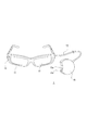
- the measuring device 1 suitable for such a way of thinking, for example, a form having a glass unit 11 as shown in FIG. 3 can be considered.
- the measuring device 1 is configured such that the glass unit 11 and the control unit 15 are connected by the cord 14.
- the glass unit 11 is of a spectacle type and can be worn by an operator like sunglasses during the grain-picking operation as shown in FIG.
- the control unit 15 has a small-sized housing, and the operator is stored in a pocket of clothes or the like.
- a camera 12 is mounted on the glass unit 11 so that the front of the worker can be photographed.
- the front of the glasses-type glass unit 11 is an on-glass display section 13.
- the on-glass display unit 13 is usually a transparent or semi-transparent liquid crystal panel or the like, and the user can see the front simply as a glass, but can perform a necessary display on the glass.
- FIG. 5 shows a state of display on the on-glass display portion 13 in a state where the user wears the glass unit 11 as shown in FIG. While the user can see the grapes 22, 23, 24 through the transparent plate serving as the on-glass display unit 13, a grain number display 25, such as the “grain number 45” shown in the figure, is performed, and is measured by this. You can check the number of grains.
- the on-glass display unit 13 may display the captured image of the camera 12 as a through image as it is, instead of being in a transparent or translucent state.
- the control unit 15 is provided with an operation button 15a, which enables, for example, power-on / off operation.
- the camera 12, the on-glass display unit 13, and the operation button 15a described above are one aspect of the imaging unit 2, the display unit 9, and the operation unit 6 in FIG. 1, respectively.
- the glass unit 11 and the control unit 15 thus configured function as the measuring device 1 by mounting the respective units having the configuration shown in FIG. 1, for example.
- the camera 12 as the imaging unit 2 the on-glass display unit 13 as an example of the display unit 9 are mounted on the glass unit 11, and the operation button 15a as an example of the operation unit 6 is mounted on the control unit 15.
- each part shown in FIG. 1 may be mounted on either the glass unit 11 or the control unit 15.
- a configuration in which all the configurations shown in FIG. 1 are provided in the glass unit 11 and the control unit 15 is not provided is also conceivable.
- the form of the measuring device 1 is not limited to the form of the glass unit 11 and the control unit 15 of FIG. 3, and other forms will be described later, but the form of FIG. 3 will be described below as an example. Go.
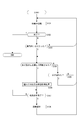
- FIG. 6 shows an example of processing executed by the control unit 5 by the functions of the measurement target identification unit 5a, the measurement unit 5b, and the presentation control unit 5c of FIG.
- the control unit 5 of the measuring device 1 executes the process of FIG. 6 while the power is turned on.
- step S101 the control unit 5 performs a waiting process.
- the standby process is a process of performing imaging by the imaging unit 2 and monitoring the analysis result of the captured image by the image analysis unit 4, the detection result by the sensor unit 7, and the operation by the operation unit 6. More specifically, the control unit 5 monitors whether or not an operation that means the end of measurement by the operation unit 6 has been performed.
- the operation which means the end of the measurement is, for example, an operation for stopping the measurement and performing various settings, an operation for shifting to another mode, a power-off operation, or the like. When such an operation is detected, the control unit 5 finishes the processing of FIG. 6 from step S102 and shifts to other necessary processing.
- control unit 5 also detects whether or not the operator's hand has entered the angle of view by the imaging unit 2. To put a hand in the angle of view means that the operator's hand is shown in the captured image captured by the image capturing unit 2.
- ⁇ Determine the presence of a hand within the angle of view by distinguishing the skin color by image analysis
- ⁇ Determining the human hand by temperature using the image captured by the thermotracer
- ⁇ To discriminate using the human hand discrimination method realized by machine learning and deep learning using the images captured by the TOF sensor and stereo camera
- ⁇ There is a method of distinguishing gloves with a specific color and pattern by the method of distinguishing gloves worn by the worker.
- a method for discriminating the gloves worn by the worker for example, a process in which the worker wears a glove with a checkered pattern as shown in FIG. 7 and the pattern is discriminated by image recognition is a process.
- the color of the gloves may be a color that is not in the farm (for example, purple) or the like, and it may be determined that the hand is within the angle of view by the color determination in the image.
- the control unit 5 monitors the timing of measurement execution. That is, the control unit 5 monitors in step S104 that the hand grips the branch of the bunch of grapes and further rotates the bunch in the gripped state.
- the following example can be considered as a means for determining that the hand has grabbed a branch.
- a pressure sensor is installed on the fingertips or gloves of the operator to determine that the branch has been grasped by the change in pressure.
- Thermotracer captures temperature changes due to blood flow changes in the fingers. In other words, it is detected by utilizing the fact that the blood flow is changed by grasping the branch.
- the control unit 5 detects that the hand of the operator whose hand is included in the captured image has once gripped the branch of the bunch of grapes, but has separated without rotating, or further the angle of view. If it is detected that it has also gone out of, the process returns from step S105 to S101.
- the control unit 5 When it is detected that the branch of the tuft is picked and rotated by the hand that has entered the angle of view, the control unit 5 automatically starts counting the number of grains starting from this. That is, the control unit 5 proceeds from step S104 to step S106, and executes the grain number measurement process for the tufts of the picked branches.
- To measure the number of grains capture images from multiple directions of the tuft by rotating the tuft and measure the number of grains that are three-dimensionally present, including the number of grains that are on the back side of the tuft. .
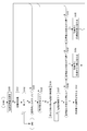
- step S106 The grain number measuring process in step S106 is shown in detail in FIG.
- step S120 of FIG. 8 the control unit 5 specifies the required number of captured images (N frames).
- N frames the required number of captured images
- the required number of frames during the period in which the worker is picking and rotating the branches of the tufts is the frame used for measurement.
- an operator can rotate the bunch of grapes by 120 to 150 degrees. This is because the branches do not usually break even if such an angle is turned.
- the frame image when rotated from about 120 degrees to about 150 degrees the grains originally on the back side also appear. Therefore, a plurality of frames in a period in which the worker rotates about 120 degrees to 150 degrees are extracted, and the number of particles is measured from there.
- the control unit 5 designates a required number (N) of frame image data among the frames of the captured image obtained at such a frame rate as a processing target.
- the N frames may be continuous frames or intermittently extracted frames, depending on the frame rate and the rotation speed. These may vary depending on the actual rotation period.
- step S122 the measurement object is specified for the nth frame specified.
- the process of specifying the measurement target object is performed for the first frame of the N frames designated as the processing target.
- the image analysis unit 4 is instructed to identify a bunch of grapes whose branches are picked by the operator's hand as a measurement target. That is, the bunch of grapes whose branches are picked by the operator's hand, which is recognized by the image analysis unit 4, is specified as the measurement target.
- a region (pixel region) as a tuft located below the operator's hand in the image is determined by image analysis, luminance edge detection, color determination, or the like.
- the pixel range of the grape tuft that is the measurement target is specified in the image of the frame that is the processing target.
- step S123 the control unit 5 (or the image analysis unit 4) measures the number of grape grains in the frame, and the control unit 5 obtains the measurement result. That is, the image of the grain is determined within the pixel range specified as the measurement target, and the number is measured.
- control unit 5 After measuring the number of particles in one frame, the control unit 5 confirms in step S124 whether or not the variable n has reached the designated frame number N, and if not, increments the variable n in step S125. It returns to step S122. Therefore, for the N frames selected as the processing target, the pixel range as the measurement target in the image is sequentially specified, and the number of particles in the pixel range is measured.
- the following example can be considered as a method for measuring the grains in the tufts at the tips of the grasped branches.
- ⁇ Measure the position of the hand with TOF and measure the number of grains in the same depth as that.
- ⁇ Measure the depth with a stereo camera or defocusing method, and then recognize each grain and measure the number of grains. Particles are detected and counted using a plurality of IR (infrared) lights having a wavelength absorbed by water and a wavelength not absorbed by water. In addition to IR, visible light or other wavelengths may be used. Grape grains contain more water than branches, and due to the difference in water content, a peak appears at a specific wavelength of infrared light corresponding to the grain. Therefore, it is possible to detect the portion of the grain having a large amount of water, which enables counting of the number of grains.
- IR infrared
- step S126 the control unit 5 sums the number of particles counted from each frame to calculate the number of particles in the entire bunch. That is, the measurement result of the number of grains in the specific grape bunch as the measurement target specified by the operator picking is obtained.
- step S107 the control unit 5 instructs the display control unit 8 to execute the grain number display 25 on the display unit 9 (for example, the on-glass display unit 13) as shown in FIG.
- the control unit 5 may generate and display not only the number of particles but also a predetermined determination result obtained from measurement.
- the measurement result may be presented not only by display but also by voice or vibration. After performing the processing for such presentation, the control unit 5 returns to the standby processing of step S101.
- the operator grasps the branch with the hand to specify the measurement target, and the measurement is executed by rotating the tuft.
- the object to be measured by the grasped branch even if a plurality of grapes 22, 23, 24 exist within the angle of view as shown in FIG. 5, for example, the grape 22 below the picked branch 22A. Only the tuft 22B is specified as the measurement object. This enables accurate measurement of each grape regardless of the reflection of the grape within the angle of view. Further, since it is not necessary to perform an extra operation such as pressing a shutter button for capturing an image, it does not hinder the granulation work. In addition, it is possible to accurately measure the number of particles by preventing the re-measurement of the particle initially measured from the image information of a plurality of frames and the information of the rotation angle of the tuft.
- FIG. 9 shows an example of processing executed by the control unit 5 by the functions of the measurement target identification unit 5a, the measurement unit 5b, and the presentation control unit 5c of FIG. It should be noted that, hereinafter, the same steps as those already described will be denoted by the same step numbers, and duplicate description will be avoided.
- the control unit 5 performs a standby process in step S101, monitors the end of the process in step S102, and monitors in step S103 whether or not the operator's hand is within the angle of view. In this example, if it is detected that the hand is within the angle of view, the control unit 5 proceeds to step S150 and determines whether the hand has picked a branch.
- step S101 when the hand appearing within the angle of view has not reached to pick the branch, the process returns to step S101, but when it is detected that the hand picks (grasps) the branch, the control unit 5 uses it as a measurement start trigger. Then, the process proceeds to step S106 to start the grain number measuring process. This process is performed, for example, as shown in FIG. In this case, the operator can accurately count the number of grains from the images of the plurality of frames by rotating the bunch of grapes.
- the control unit 5 proceeds from step S107 to step S108, and performs presentation control of the grain number as a measurement result.
- the process of FIG. 9 is an example in which it is determined that the hand has picked a branch and the measurement is started. It should be noted that in this example, the hand starts picking a branch to start the measurement, but it is possible that the worker does not rotate the tuft. Therefore, if the rotation of the tuft is not detected for a predetermined time or longer, the measurement may be ended in error. Alternatively, the measurement may be performed regardless of whether or not the tuft is rotated. For example, when it is detected that the grape has been rotated, the number of grains is measured in the process of FIG. 8 using images of a plurality of frames in which the cluster of grapes is viewed from different directions. On the other hand, when the image is not rotated, the images in each frame are almost the same.
- the number of grape grains is measured from the image of one frame (the image seen from one direction), and the coefficient is multiplied as in the fourth embodiment described later to estimate the number of grains on the back side (not shown in the image). The values are obtained, and the number of grains in the entire tuft is calculated from them.
- the measurement target object there may be an object or a feature amount that allows accurate measurement regardless of whether or not the measurement target object is rotated. In such a case, it is possible to start the measurement triggered by gripping the object, and appropriately specify the measurement target object based on the image from one direction or the sensing information to measure the feature amount.
- processing example of the third embodiment will be described with reference to FIG.
- the processing of FIG. 10 is also an example of processing executed by the control unit 5 by the functions of the measurement target identification unit 5a, the measurement unit 5b, and the presentation control unit 5c of FIG. 2. The difference from FIG. That is, the processing of steps S151 and S152 is performed in the state where it is detected.
- control unit 5 determines in step S150 that the hand has picked a branch, it does not immediately determine that the measurement has started, but in step S151 monitors whether a measurement start trigger is detected, and in step S152 Monitor whether or not they have left.
- the control unit 5 detects the trigger for starting the measurement based on the determination result from the image by the image analysis unit 4 and the detection information by the sensor unit 7.
- control unit 5 Even if the operator's hand once grips the branch of the bunch of grapes, the control unit 5 detects that the trigger has been released without being detected, or that the operator has also left the angle of view. If detected, the process returns from step S152 to S101.
- step S151 the control unit 5 proceeds from step S151 to step S106 and starts the grain number measuring process. This process is performed, for example, as shown in FIG. In this case, the operator can accurately count the number of grains from the images of the plurality of frames by rotating the bunch of grapes.
- step S107 the control unit 5 proceeds from step S107 to step S108, and performs presentation control of the grain number as a measurement result.
- a predetermined action as a trigger is assumed to be a vocal action of the worker, a sound action such as generating a predetermined sound, or a gesture action by the worker's hands or tools (scissors, etc.).
- ⁇ Speak with the branches picked by hand ⁇ Speak the prescribed words with the branches picked by hand.
- ⁇ Produce a predetermined sound with the branches picked by hand (sound of a tree, sound of scissors for grain selection, etc.).
- -Perform a predetermined gesture that can be recognized by the captured image with the branch picked by the hand (put the other hand in the angle of view, insert scissors in the angle of view, etc.).
- Performing a predetermined gesture that can be detected by the sensor unit 7 with the branch picked by the hand (striking the ground with a foot, shaking the other hand (detected by vibration or pressure), etc.).
- Grapes of grapes are three-dimensionally arranged around the branches, and the accurate number cannot be grasped only from the image taken from one direction. Therefore, in the first embodiment, a plurality of grapes are rotated when the cluster of grapes is rotated. It is assumed that measurement is performed from the frame image. However, measurement may be performed by imaging from one direction. In that case, it is conceivable to estimate and measure the number of grains in the tuft by calculating the product of the number of grains measured from an image in one direction and a predetermined coefficient value. Such an example is shown in FIG. 11 as a fourth embodiment.
- the control unit 5 performs the standby process in step S101 of FIG. 11, monitors the end of the process in step S102, and monitors whether the operator's hand is within the angle of view in step S103. Further, when it is detected that the hand has entered the angle of view, the control unit 5 proceeds to step S150 and determines whether the hand has picked a branch.
- step S101 when the hand appearing within the angle of view has not reached to pick the branch, the process returns to step S101, but when it is detected that the hand picks (grasps) the branch, the control unit 5 uses it as a trigger to start measurement. Then, the particle number measuring process from step S170 is executed.
- step S170 the control unit 5 designates an image of a certain imaged frame, and in step S171, performs a process of specifying a measurement object in the image.
- the image analysis unit 4 is instructed to identify a bunch of grapes whose branches are picked by the operator's hand as a measurement target.
- the image analysis unit 4 determines a region (pixel region), which is located under the operator's hand, as a tuft in the image of the one frame by image analysis, luminance edge detection, color determination, or the like, and the measurement target object is measured.
- the pixel range of the bunch of grapes is specified.
- step S172 the control unit 5 (or the image analysis unit 4) measures the number of grape grains within the pixel range of the measurement target, and the control unit 5 obtains the measurement result. That is, the image of the grain is determined within the pixel range specified as the measurement target, and the number is measured.
- step S173 the control unit 5 multiplies the acquired measurement result by a preset coefficient.
- the number of grains measured from the image is the number of grains on the front side that appear as the subject of the image capturing unit 2 when the image is captured.
- the coefficient is, for example, a coefficient for estimating the number of grains on the back side that are not shown in the captured image. Therefore, the number of grains on the back side is estimated by multiplying the measured number of grains by a coefficient.
- step S174 the control unit calculates the total number of grains in the tuft from the measured number of grains on the front side and the number of grains on the back side estimated by the coefficient multiplication. As a result, the measurement result of the bunch of grapes that is the measurement target is obtained. Then, in step S175, the control unit 5 performs a grain number presentation process. For example, the control unit 5 instructs the display control unit 8 to execute the grain number display 25 on the display unit 9 (for example, the on-glass display unit 13) as shown in FIG.
- the fifth embodiment has a function of setting a target value of the number of grains, and a function of notifying a worker of difference information with the target value and arrival of the target value.
- FIG. 12 shows a processing example of the fifth embodiment. 12 is an example of processing executed by the control unit 5 by the functions of the measurement target specifying unit 5a, the measuring unit 5b, the presentation control unit 5c, and the target setting unit 5d in FIG.
- step S100 the control unit 5 sets a target value for the number of grains.
- a target value is determined based on an input operation of a target number of particles by an operator, and the target value is stored in the storage unit 10.
- a target value such as “35 grains” is set.
- the control unit 5 performs a standby process in step S101, monitors the end of the process in step S102, and monitors in step S103 whether or not the operator's hand is within the angle of view. When detecting that the hand has entered the angle of view, the control unit 5 proceeds to step S150 and determines whether the hand has picked a branch.
- step S101 when the hand appearing within the angle of view has not reached to pick the branch, the process returns to step S101, but when it is detected that the hand picks (grasps) the branch, the control unit 5 uses it as a measurement start trigger. Then, the process proceeds to step S106 to start the grain number measuring process.
- This process is performed, for example, as shown in FIG. Also in this case, the operator can accurately measure the number of grains from the images of the plurality of frames by rotating the bunch of grapes, but the measurement algorithm may be switched depending on whether the operator rotates the grape cluster. For example, the measurement algorithm that uses a plurality of frames and the algorithm that uses one frame and the coefficient for estimating the backside grain number are switched depending on whether or not to rotate.
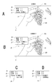
- the particle number display 25 the numerical value is not displayed because it is still being measured.
- the target display 26 the set target value (for example, “35”) is displayed. “Measuring” is displayed as the status display 27. By displaying in this way, the operator can clearly recognize the target value.
- step S180 the control unit 5 compares the number of particles obtained by the particle number measurement process with the stored target value, and determines whether the difference is 6 or more.
- step S181 the control unit 5 proceeds to step S181 and performs a process of presenting the number of particles and the like to the operator.
- the control unit 5 generates information such as the number of particles, the target value, the status, the situation, etc., transmits it to the display control unit 8, and causes the display unit 9 to display it.
- FIG. 13B shows a display example of the display unit 9.
- a measured value for example, “45” is displayed as the grain number display 25.
- the set target value for example, “35” is displayed.
- “Measurement completed” is displayed as the status display 27.
- the current status is displayed as the status display 28. In this case, since the number of grains is still large, "large” is displayed. By displaying in this way, the operator can clearly recognize the current number of grains, the target value, and the situation.
- control unit 5 returns to step S106 and performs the grain number measurement process again. That is, after the operator starts the grain selection work, the grain number measurement process is repeatedly executed.
- step S180 Every time the grain number measurement is completed, the processing from step S180 is performed. If it is determined in step S180 that the difference from the target value is not 6 or more (that is, 5 or less), the control unit 5 proceeds to step S182, and if the difference is 5, proceeds to step S184. In this case, the control unit 5 instructs the display control unit 8 to display, as a display for the worker, a display indicating that the target is five after. For example, the display of the content as shown in FIG. 13C is executed (in FIG. 13C and FIG. 13D, only the presentation content portion based on the measurement is shown).
- the measured value “40” is displayed as the grain number display 25
- the target value “35” is displayed as the target display 26
- “measurement completed” is displayed as the status display 27.
- a display such as "5 more” is executed as the status display 28.
- the process of the control unit 5 returns to step S106 to repeat the grain number measuring process.
- the display is made at the timing of the remaining five until the target, but of course the timing is various, and the display is made such as "3 more" at the timing of the remaining three. Good.
- step S182 when the differences are 4, 3, 2, and 1, respectively, it does not correspond to the determinations in steps S182 and S183, and thus the process returns to step S106 without any particular notification.
- the difference is determined to be 5 or less in step S180 as described above, the remaining number is displayed regardless of the number of differences, so that the remaining number is changed, for example, in a countdown display. You may go.
- the process of the control unit 5 proceeds from step S183 to S185, and the control unit 5 notifies the target arrival.
- the display control unit 8 is controlled as described above. For example, as shown in FIG. 13D on the display unit 9, the measurement value “35” is displayed as the grain number display 25, the target value “35” is displayed as the target display 26, the “measurement is completed” as the status display 27, and the “target number reached” as the status display 28. The display like this is executed. As a result, the granulation work for this tuft is completed, so that the process of the control unit 5 returns to the waiting process of step S101.
- the worker can accurately perform grain selection up to the target grain number.
- an appropriate graining operation can be performed without being required by a skilled person or depending on the physical condition.
- FIG. 14 shows an example in which the grain to be grained is designated as the grained portion display 30 for the guide.
- the grain to be grained is designated as the grained portion display 30 for the guide.
- an algorithm is provided that selects grains that are densely packed preferentially, and the grains to be thinned are selected according to the number of remaining grains and the density of the grains, and the selected grains are displayed by the grain-pulling position display 30.
- the particles to be cut off in this way, even an inexperienced operator can make the particles have a uniform density after the plucking.
- FIG. 15A is an example in which a measurement system is configured by the glass unit 11A and the information processing device 50.
- the information processing device 50 a mobile terminal such as a smartphone or a tablet is assumed.
- FIG. 15B is also an example in which a measurement system is configured by the glass unit 11A and the information processing device 50, but it is assumed that the information processing device 50 is a notebook type or desktop type personal computer.
- the following operation mode (M1) ( M10) is possible.
- various sensors as the sensor unit 7 may be mounted on both the glass unit 11A side and the information processing device 50 side.
- the mounting location may differ depending on the type of sensor.
- the detection information of various sensors may be acquired (detection or reception of detection information) on the side of the device that performs the specific processing of the measurement target or the measurement processing.
- (M1) An image is captured by the glass unit 11A and the image is transmitted to the information processing device 50.
- the information processing device 50 identifies the measurement target and performs measurement processing, and further presents the measurement result and the like.
- (M2) An image is captured by the glass unit 11A and the image is transmitted to the information processing device 50.
- the information processing device 50 specifies the measurement target and performs measurement processing, and transmits information such as the measurement result to the glass unit 11A.
- the measurement results and the like are presented on the glass unit 11A side.
- the glass unit 11A captures an image to specify the measurement target and perform measurement processing. Then, the information such as the measurement result is transmitted to the information processing device 50.
- the information processing device 50 presents measurement results and the like.
- (M4) An image is captured by the glass unit 11A to identify the measurement target, and the captured image and information indicating the identified measurement target are transmitted to the information processing device 50.
- the information processing device 50 performs measurement processing, and further presents measurement results and the like.
- (M5) An image is captured by the glass unit 11A to identify the measurement target, and the captured image and information indicating the identified measurement target are transmitted to the information processing device 50.
- the information processing device 50 performs a measurement process and transmits the measurement result to the glass unit 11A. The measurement results and the like are presented on the glass unit 11A side.
- the information processing device 50 captures an image and transmits the image to the glass unit 11A.
- the glass unit 11A identifies the measurement target and performs measurement processing, and further presents measurement results and the like.
- the information processing device 50 captures an image and transmits the image to the glass unit 11A.
- the glass unit 11A identifies the measurement target and performs measurement processing, and transmits information such as the measurement result to the information processing device 50.
- the information processing device 50 presents the measurement results and the like.
- An image is captured by the information processing device 50, the measurement target is specified and measurement processing is performed, and information such as the measurement result is transmitted to the glass unit 11A.
- the measurement results and the like are presented on the glass unit 11A side.
- the information processing device 50 captures an image, identifies the measurement target, and transmits the captured image and information indicating the identified measurement target to the glass unit 11A.
- the glass unit 11A performs measurement processing, and further presents measurement results and the like.
- the information processing device 50 captures an image, identifies the measurement target, and transmits the captured image and information indicating the identified measurement target to the glass unit 11A.
- the glass unit 11A performs measurement processing, and transmits the measurement result and the like to the information processing device 50.
- the information processing device 50 presents the measurement results and the like.
- the glass unit 11A and the information processing device 50 form a measurement system, and the glass unit 11A functions as a measurement terminal.
- the measurement terminal A configuration example as 1A can be considered as shown in FIG.
- the measurement terminal 1A includes an imaging unit 2, an image signal processing unit 3, a control unit 5, an operation unit 6, a sensor unit 7, a storage unit 10, and a communication unit 16. That is, the image analysis unit 4, the display control unit 8, and the display unit 9 in the configuration of FIG. 1 are not provided, but the communication unit 16 is provided.
- the image pickup unit 2, the image signal processing unit 3, the control unit 5, the operation unit 6, the sensor unit 7, and the storage unit 10 are the same as those described in FIG. However, in the case of the above (M1) mode, the control unit 5 may not have the functional configuration shown in FIG.
- the communication unit 16 performs wired or wireless data communication or network communication with an external device.
- the communication unit 16 is provided to communicate with the information processing device 50.
- a short-range wireless communication unit such as Bluetooth (registered trademark) can be considered.
- the communication unit 16 performs communication via various networks such as the Internet, home network, LAN (Local Area Network), etc., and transmits / receives various data to / from servers, terminals, etc. on the network. You may
- the glass unit 11A may have the configuration of FIG.
- the control unit 5 has the function of the presentation control unit 5c in the configuration of FIG. 16, and the display control unit 8 and the display unit 9 of FIG. 1 may be added.
- the control unit 5 has the functions of the measurement target specifying unit 5a and the measurement unit 5b in the configuration of FIG. 16, and the image analysis unit 4 may be provided.
- the control unit 5 has the function of the measurement target specifying unit 5a in the configuration of FIG. 16, and the image analysis unit 4 may be provided.
- control unit 5 In the operation mode of (M5), in the glass unit 11A, the control unit 5 has the functions of the measurement target specifying unit 5a and the presentation control unit 5c in the configuration of FIG. 16, and the image analysis unit 4, the display control unit 8, and the display unit. 9 may be provided.
- the control unit 5 In the operation mode (M6), in the glass unit 11A, the control unit 5 has the functions of the measurement target identification unit 5a and the measurement unit 5b in the configuration of FIG. 16, and the image analysis unit 4, the display control unit 8, and the display unit 9 are included. Should be added. The image pickup unit 2 and the image signal processing unit 3 are unnecessary. In the case of the operation mode (M7), in the glass unit 11A, the control unit 5 has the functions of the measurement target specifying unit 5a and the measuring unit 5b in the configuration of FIG. 16, and the image analysis unit 4 may be added. The image pickup unit 2 and the image signal processing unit 3 are unnecessary. In the case of the operation mode (M8), the glass unit 11A only needs to include the display controller 8 and the display 9 in the configuration of FIG.
- the control unit 5 has the function of the measurement unit 5b in the configuration of FIG. 16, and the image analysis unit 4, the display control unit 8, and the display unit 9 may be provided.
- the glass unit 11A may be configured such that the control unit 5 has the function of the measurement unit 5b and the image analysis unit 4 in the configuration of FIG.
- the hardware configuration of the information processing device 50 can be realized by a configuration as a computer device as shown in FIG. 17, for example.
- the CPU 171 executes various processes according to a program stored in the ROM 172 or a program loaded from the storage unit 178 to the RAM 173.
- the RAM 173 also appropriately stores data necessary for the CPU 171 to execute various processes.
- the CPU 171, the ROM 172, and the RAM 173 are connected to each other via a bus 174.
- An input / output interface 175 is also connected to the bus 174.
- the input / output interface 175 includes an input unit 176 including a keyboard, a mouse, a touch panel, a display including an LCD or an organic EL panel, an output unit 177 including a speaker, a storage unit 178 including a hard disk, a modem, and the like.
- a communication unit 179 composed of the above is connected.
- the communication unit 179 performs communication processing via a network such as the Internet, and performs communication with peripheral devices by wired / wireless communication, bus communication, or the like.
- the communication unit 179 is provided to communicate with the glass unit 11A, and in that case, it is an example such as a short-range wireless communication unit such as Bluetooth. Can be considered.
- a drive 180 is also connected to the input / output interface 175 as necessary, a removable medium 181 such as a magnetic disk, an optical disk, a magneto-optical disk, or a semiconductor memory is appropriately mounted, and a computer program read from them is It is installed in the storage unit 178 as needed.
- a removable medium 181 such as a magnetic disk, an optical disk, a magneto-optical disk, or a semiconductor memory is appropriately mounted, and a computer program read from them is It is installed in the storage unit 178 as needed.
- a sensor unit 184 may also be connected to the input / output interface 175. As the sensor unit 184, various sensors can be considered as in the sensor unit 7 of FIG.
- the information processing device 50 includes the image capturing unit 182 and the image signal processing unit 183 in order to capture an image, and the image signal processing unit 183 is connected to the input / output interface 175. .
- the imaging unit 182 and the image signal processing unit 183 are the same parts as the imaging unit 2 and the image signal processing unit 3 in FIG.
- the image pickup unit 182 and the image signal processing unit 183 are not necessary in the cases of the above (M6) to (M10). In other words, it does not have to be installed, or even if it is installed, it does not have to be used. However, it is possible that the image pickup unit 182 is used as a sensor.
- the configuration according to each operation mode is as follows.
- the information processing apparatus 50 may have the configuration of FIG. 17, and in particular, the CPU 171 is provided with the functions of the measurement target identification unit 5a, the measurement unit 5b, and the presentation control unit 5c.
- the CPU 171 may have the functions of the measurement target specifying unit 5a and the measuring unit 5b in the configuration of FIG.
- the CPU 171 may have the function of the presentation control unit 5c in the configuration of FIG.
- the CPU 171 may have the functions of the measurement unit 5b and the presentation control unit 5c in the configuration of FIG.
- the CPU 171 in the information processing device 50, the CPU 171 may have the function of the measurement unit 5b in the configuration of FIG.
- the information processing device 50 may have the configuration of FIG.
- the CPU 171 in the information processing device 50, the CPU 171 may have the function of the presentation control unit 5c in the configuration of FIG.
- the CPU 171 in the information processing device 50, the CPU 171 may have the functions of the measurement target specifying unit 5a and the measuring unit 5b in the configuration of FIG.
- the CPU 171 in the information processing device 50, the CPU 171 may have the function of the measurement target specifying unit 5a in the configuration of FIG.
- the CPU 171 in the information processing apparatus 50, the CPU 171 may have the functions of the measurement target specifying unit 5a and the presentation control unit 5c in the configuration of FIG.
- the CPU 171 may be provided with the functions of the measurement target identification unit 5a, the measurement unit 5b, and the presentation control unit 5c. Although not mentioned, it may have a function as the target setting unit 5d.
- the programs forming the software are installed from a network or a recording medium.
- This recording medium is composed of a removable medium 181 which is distributed in order to distribute the program to a user, and which includes a magnetic disk, an optical disk, a magneto-optical disk, a semiconductor memory, or the like on which the program is recorded.
- it is also configured by a ROM 172 in which a program is recorded and a hard disk included in the storage unit 178, which is distributed to the user in a state of being incorporated in the apparatus body in advance.
- the above is a configuration example in the case of a measurement system including the glass unit 11A and the information processing device 50 as shown in FIGS. 15A and 15B.
- This is a measurement terminal 1A as a wearable (body-wearable) unit It can be regarded as a system based on the device 50.
- the body-mounted unit is a unit that can be mounted on a person's body or clothes. In that sense, various body-mounted units are assumed in place of the glasses-shaped glass unit 11A. For example, head-mounted type, earphone type, wristband type, clothes type, clip type, pocket storage type, pendant type and the like are assumed.
- FIG. 15C illustrates a case where the information processing device 50 as a mobile terminal such as a smartphone is the measurement device 1 of the embodiment.
- the information processing device 50 has the same configuration as in FIG. 1, and the worker uses the information processing device 50 (smartphone) to image grapes.
- the measurement is performed by performing the processing as in the first to fourth embodiments, and the grain number display 25 as the measurement result is performed as shown in FIG. 18A.
- FIG. 18B both the captured image display 29 and the grain number display 25 as the measurement result may be displayed.
- FIG. 15D illustrates a case where the imaging system 60 and the information processing device 50 form a measurement system.
- the imaging device 60 is a normal video camera, and the information processing device 50 substantially functions as the measuring device 1. That is, the information processing device 50 performs the operation as the measuring device 1 (processing of the first to fourth embodiments) using the captured image transmitted by communication.
- the imaging device 60 and the information processing device 50 it is also conceivable to combine the imaging device 60 and the information processing device 50 to form a measurement system.
- FIG. 19 shows the configuration of a measurement system via network communication.
- FIG. 19A shows the glass unit 11A, the communication terminal 51, the network 52, and the cloud server 53.
- the network 52 includes the Internet, LAN, VPN (Virtual Private Network), intranet, extranet, satellite communication network, CATV (Community Antenna Tele Vision) communication network, telephone line network, mobile communication network, and the like. The form is assumed.
- the cloud server 53 is composed of an information processing device.
- the cloud server 53 and the communication terminal 51 can be realized as a computer device as shown in FIG. 17, for example.
- the glass unit 11A transmits a captured image and sensor information to the communication terminal 51.
- the communication terminal 51 is, for example, a smartphone, a tablet, a dedicated terminal, or the like, and is an information processing device capable of network connection.
- the captured image, sensor information, and the like from the glass unit 11A are transmitted from the communication terminal 51 to the cloud server 53 via the network 52.
- the cloud server 53 has the functions of the measurement target specifying unit 5a and the measuring unit 5b to measure the number of particles and return the measurement result.
- the glass unit 11A displays the measurement result by receiving the measurement result via the network 52 and the communication terminal 51. In this way, it is also possible to build a measurement system using a so-called cloud service.
- FIG. 19B shows an AI engine 54 added to the configuration of FIG. 19A.
- the AI engine 54 performs measurement target identification processing and measurement processing based on image analysis. This makes it possible to perform highly accurate measurement processing, determination of measurement execution, and the like.
- the glass unit 11A which is a body-worn unit, may directly communicate with the network so that the communication terminal 51 is unnecessary.
- the measuring apparatus 1 includes a measurement target specifying unit 5a that performs a process of specifying a measurement target based on detection of gripping a grape branch (object) by an operator's hand (gripping body), and a measurement target specifying.
- the measuring unit 5b includes a measurement unit 5b that obtains a measurement result by the measurement process of the characteristic amount of the measurement target specified by the unit 5a. That is, in the embodiment, the measurement target is specified by detecting the action of grasping the branch by the gripping body such as the hand of the operator.
- the bunch of grapes is specified as the measurement target, and the characteristic amount, for example, the number of grains is measured.
- the measurement object can be clearly specified in the process of work in which an opportunity to grip the object occurs.
- the range to be measured becomes clear in the captured image.
- the act of gripping a branch with a hand is a part of the work to be performed (eg, grain selection) or an action leading to the work, it is possible to accurately specify the measurement target object in the natural flow of the work. become. As a result, it is possible to correctly set and measure the measurement target object for providing the worker with necessary information without requiring the worker to perform some extra action or operation.
- the usability is improved, the efficiency of the granulation work is improved, and the measurement accuracy is also improved.
- many bunches of grapes are included in the captured image.
- the process may become unstable in terms of which part of the image to measure the number of particles, but in the present embodiment, the measurement is performed by pinching a branch in the process of work. Since the power cell is specified, the number of particles in the cell desired by the worker can be correctly set as the measurement object in the process in which the worker performs normal work. Particularly in the case of agricultural crops in which fruits such as grapes and bananas form a tuft, it is very useful that the tuft to be measured is specified by gripping.
- grapes are given as an example, but the present technology is applicable to measurement of various objects such as crops such as bananas and tomatoes, natural objects such as trees and animals, and industrial products. Applicable.
- the measurement target is all or part of the objects specified by gripping among these various objects.
- the feature quantity is the number of grains, but in addition to the quantity, size (size), color, ingredient content, ingredient ratio, sugar content, water content, estimated price, etc. can be quantified and compared and evaluated. Therefore, the present technology can be widely applied to those measuring devices.
- the measurement apparatus 1 includes a presentation control unit 5c that performs processing for presentation based on the measurement result. This allows the operator to know information such as the number of grains in a bunch of grapes that holds the branches. That is, the measuring device 1 can provide appropriate information during the work process of the worker.
- the presentation based on the measurement result is not limited to the value of the measurement result itself of the feature amount, but may be appropriateness determination information or guide information according to the measurement result. For example, instead of the numerical value as the measurement result, the judgment information such as “appropriate”, “impossible”, “appropriate number”, “insufficient”, “excessive”, or by showing the guide content for the subsequent work, Precise work support is possible.
- the presentation device is not limited to the display unit 9 and includes a voice output unit, a vibration unit, and the like, the presentation control unit 5c presents the measured feature amount in a presentation mode according to these presentation devices. It may be controlled to be performed.
- the example in which the measurement process is performed using the captured image has been described.
- a captured image obtained by capturing an object by the integrated or separate imaging unit 2 is input.
- the feature amount that can be determined from the image is measured.
- a feature amount such as the number of grape grains.
- stable measurement is possible and the measurement accuracy can be improved. Note that not only the captured image but also the detection information from the sensor unit 7 can be used for measurement.
- the example in which the measurement process is executed based on the detection that the gripping body grips the object has been described (see FIGS. 9 and 11). That is, when the grasping of the object by the grasping body is detected, the measurement of the feature amount of the measurement object is started.
- the measurement target is specified based on the grip
- the worker does not perform a special operation (operation for instructing the start of measurement)
- the required measurement will be performed.
- the operation of pinching the branches of the tuft is an operation in the normal flow of work, so that the operator can perform the measurement at an appropriate timing without being aware of the measurement operation at all. Therefore, usability is greatly improved.
- gripping can also provide an appropriate measurement start timing depending on the object to be measured and the characteristic amount to be measured.
- the measurement process is executed based on the detection that the object is held by the holding body and the object is moved (see FIG. 8).
- the measurement of the feature amount of the measurement target is started when some movement is applied to the object while being gripped.
- the movement is supposed to be shaken, pinched and moved up and down, left and right, back and forth, shaken, and rotated.
- the measurement of the measurement target may require movement of the measurement target.
- movement for example, rotation of the tuft in addition to gripping may be a natural operation during work.
- the measurement is performed when the pinching operation and the movement are detected, so that the measurement is appropriately performed when necessary. Further, since no special operation (operation for instructing the start of measurement) of the worker is required, the operation load does not occur. Furthermore, moving an object in a grasped state (for example, moving it up and down, left and right, front and back, rocking, and rotating in a pinched state) can be positioned as a conscious measurement start operation by an operator. it can. In that case, it is possible to instruct the apparatus to start measurement as a simple operation that continues from gripping. For example, it is suitable when it is desired to execute the measurement not only by picking but also by some kind of trigger.
- the example in which the measurement process is performed based on the detection of a predetermined action other than the gripping of the object by the gripping body has been described.
- a predetermined action is assumed to be a voice action of the worker, a sound action such as generating a predetermined sound, and a gesture action using a tool (scissors, etc.) held by the worker.
- Performing a predetermined action by the worker in the gripped state is an operation for starting measurement. This allows the operator to instruct the apparatus to start measurement at an appropriate timing in the gripped state.
- a predetermined action other than the gripping body by performing a predetermined action other than the gripping body, it is possible to easily give an instruction in a gripped state (picking grape branches). Specifically, if the operator's utterance, the operator's predetermined words are uttered, or sound is generated (the other hand of the picked hand or something held in the hand to generate some sound), There is no hindrance. In addition, for example, putting the other hand into the image and making a predetermined gesture with the hand picking the branch, putting the scissors held by the other hand in the angle of view of the imaging unit 2, making a predetermined gesture, etc. Also, in this case, the operation will not be a burden during the work.
- the example in which the measurement process is performed using the images of the plurality of frames captured during the period in which the measurement target object is moved has been described (see FIG. 8).
- a captured image obtained by capturing an object by the image capturing unit 2 is input, but measurement is performed using a plurality of frames of an image obtained as a moving image.
- the feature amount can be accurately detected even when there is a front surface and a back surface.
- both the grain on the front side and the grain on the back side can be measured from the image captured while rotating. This can improve the measurement accuracy.
- the measurement target specifying unit 5a has described the example in which the object held by the gripping body and moved is used as the measurement target (see FIG. 6).
- an object or a part of the object to which some movement is applied in the gripped state is set as the measurement object.
- the movement includes being pinched and moved up and down, left and right, back and forth, shaken, and rotated.
- the target setting unit 5d that sets the target value of the feature amount is provided, and the target setting unit 5d is configured to obtain the difference value between the feature amount and the target value measured in the measurement process (see FIG. 12). ).
- the target value of the feature amount is set and stored by user setting or automatic setting so that it can be compared with the measured value. For example, when setting the number of particles as a target value during the granulating work, by comparing this with the measured number of particles, it is possible to obtain difference information indicating how much more particles should be granulated.
- the presentation control unit 5c that performs processing for presenting the difference value between the feature amount measured in the measurement processing and the target value is provided (see FIGS. 12 and 13).
- the presentation control unit 5c presents the difference between the current feature amount and the target value by a method such as display or voice.
- a method such as display or voice.
- an example in which the movement as the trigger of the measurement process is the rotational movement of the bunch of grapes is given (see FIG. 6).
- the rotational movement of the bunch of grapes is given (see FIG. 6).
- detection of rotational movement may be used to specify the measurement target.
- the object to be measured can be more accurately specified as a rotating tuft.
- the human hand is used as the gripping body for gripping to specify the measurement target, but an instrument operated by a human or a robot arm that automatically operates may be used.
- the human hand includes a bare hand and a gloved hand.
- the gripping body may be an instrument, but the instrument means a person's intention in any form, such as an instrument operated manually by a person, an instrument operated by a person other than the hand, an instrument attached to the hand, and an instrument operated remotely. Indicates any device that can be gripped with.
- the opposite hand has scissors during the grain picking operation, it may be possible to detect gripping by the scissors.
- various tools may be used in the work.
- As a measuring device for work using a tool it is effective to detect gripping by the tool and specify a measurement target.
- it may be useful to detect grasping by a robot arm used for factory automation or the like for specifying a measurement target.
- a robot arm By specifying the measurement object by gripping with a robot arm, such as when cultivating agricultural products, working processes during shipment, measurement on distribution lines, measurement on processed food production lines, etc., measurement on industrial product production lines, etc. It is assumed that accurate measurement is possible.
- a human hand, an instrument, or a robot arm is assumed as the grasping body, that is, if it can be grasped, an object grasped by the grasping object can be an object to be measured.
- an object grasped by the grasping object can be an object to be measured.
- the object to be measured is grape, that is, an agricultural crop.
- the measurement target specifying unit specifies an individual of the gripped agricultural product among the agricultural products as a measurement target.
- Agricultural crops are broadly defined agricultural crops and include fruits, vegetables, grains, trees, flowers, mushrooms, fertilizers, feeds, horticultural crops, industrial crops, and the like. According to the technique of the embodiment, it is possible to widely provide the measuring device 1 for such various agricultural crops.
- the measurement target specifying unit 5a performs a process in which a bunch of grapes whose branches are gripped by the gripping body is set as a measurement target, and in the measurement process, as a feature amount of the bunch of grapes set as the measurement target.
- An example of measuring the number of particles is given. That is, the bunch of grapes from which the branches have been plucked is set as the measurement target, and the number of grains in the bunch is measured. For each bunch of grapes present in the plantation, the branches are picked to identify the bunch to be measured, and the number of grains is measured. As a result, it is possible to accurately measure the number of grains for each tuft, and it is possible to accurately provide the operator with the number of grains information necessary for the grape plucking operation.
- the measuring apparatus 1 includes the image capturing unit 2 that captures an image used for the measurement process.
- the measuring unit 5b analyzes the image picked up by the image pickup unit 2 to measure the number of particles. Since the image pickup unit 2 is provided in the measuring device 1, a separate image pickup device may be prepared or installed. It is not necessary to do so, and it is possible to provide a measuring device having good usability in the process of granulation and the like. 1 and 3, the example in which the imaging unit 2 (camera 12) is built in is described, but the imaging unit 2 may be provided as a separate device.
- the imaging unit (camera 12) that captures an image used for the measurement process and the presentation unit (on-glass display unit 13) that presents the measurement result are provided.
- the worker can simply attach the body-mounted unit to the equipment for imaging the measurement target and displaying the measurement result. You don't have to care.
- the glasses unit 11 is equipped with the camera 12 and the glass unit 11 including the on-glass display unit 13, it is possible to perform the work without worrying about the device arrangement and the shooting direction. You can check the number of grains accurately.
- the presentation unit refers to a unit capable of presenting the measurement result to the user, for example, a display unit, a voice output unit, a vibration unit, or the like, which can present some information to the user's five senses. It is naturally conceivable that a speaker and an amplifier circuit as an audio output unit, an actuator as a vibrating unit, and the like are provided in a body-mounted unit such as the glass unit 11.
- the on-glass display unit 13 in which information is displayed on the display surface arranged in front of the user is taken as an example of the presentation unit. This allows the operator to confirm the measurement result in the field of view for work. In other words, the measurement information can be viewed naturally in the work process without having to pay attention to the measurement results one by one, which is very suitable in terms of work efficiency.
- the embodiment has described the example in which the sensor unit 7 that detects the grip of the object by the grip body is provided.
- a gripping body such as a human hand, an instrument, or a robot arm
- an imaging device that detects an image, pressure, temperature information, distance measurement information, a pressure sensor, a thermotracer, a measuring unit, or the like.
- Distance sensors and the like are assumed. Based on the information obtained by the sensor unit 7 or the image pickup unit 2, it is possible to detect gripping of an object by a gripping body such as a human hand, an instrument, or a robot arm, thereby identifying the measurement target and determining the measurement start timing. Can be executed properly.
- the measuring device 1 of the embodiment may have the following configuration. Since the image pickup unit 2 may be backlit depending on the work posture during the grain picking work, it is desirable that the image sensor in the image pickup unit 2 has a dynamic range of ISO 10000 or more. Further, the image pickup unit 2 may be provided with an automatic exposure function (Automatic Exposure) and a function capable of automatically switching a neutral density filter (such as a liquid crystal variable ND filter). The measurement accuracy can be improved by using the image captured by the image capturing unit 2.
- Auto Exposure Automatic Exposure
- a neutral density filter such as a liquid crystal variable ND filter
- the measuring device 1 since it is assumed that the measurement device 1 is operated in the rain, it is desirable that the measuring device 1 has a waterproof structure.
- the front lens or the cover glass of the image pickup unit 2 may be subjected to water repellent treatment.
- the object to be grasped shakes and the crop shakes and the image blurs
- the measuring device 1 vibrates, its movement is detected by a gyro sensor (angular velocity sensor), an acceleration sensor, or the like, and pixels are electronically moved according to the detected amount to correct blur, or a lens or It may have means for mechanically moving the image sensor or the camera module to correct the blur.
- the measuring device 1 may measure the sugar content, the estimated price at shipping, the number of grains per unit area, and the number of grains to be thinned, and notify the worker.
- the feature amount is not limited to the number of grains. It is also possible to set an appropriate number of grains for each tuft or each area in the farm and to provide work support such as notifying the workers.
- the locus of movement of the measuring device 1 is detected by a gyro sensor, an acceleration sensor, a GPS receiver, a geomagnetic sensor, and the like, and the feature amounts obtained by the measuring device 1 are associated and mapped to improve the efficiency of farm management. It is also possible to consider
- the number of grains in each bunch is measured while automatically moving in the farm, and the grain is plucked, or the number of grains is measured at night, and the operator the next morning, how many grains are bunched. It is also effective to use a system that tells you what to do or what to do.
- the measurement start timing and the measurement result may be transmitted to the operator by voice or video.
- the measurement start timing is notified by electronic sound or the like. This allows the user to understand the measurement operation of the measuring device 1.
- the measuring device 1 may be provided with a part as a microcomputer or a processor for performing these processes, and it may be a part as a control part, a part as an image analysis part, or another part.
- the program according to the embodiment is a program that causes, for example, a CPU, a DSP, or the like, or a device including these to execute the processes of FIGS. 6, 8, 9, 10, 11, and 12. That is, the program of the embodiment includes an information processing apparatus that performs a process of specifying a measurement target object based on detection of gripping of an object by a gripping body, and a process of obtaining a measurement result by a measurement process of a feature amount of the specified measurement target object. It is a program to be executed by.
- the measuring device 1 and the information processing device 50 described above can be realized by such a program.
- Such a program can be recorded in advance in an HDD as a recording medium built in a device such as a computer or a ROM in a microcomputer having a CPU.
- a flexible disc a CD-ROM (Compact Disc Read Only Memory), an MO (Magnet optical) disc, a DVD (Digital Versatile Disc), a Blu-ray disc (Blu-ray Disc (registered trademark)), a magnetic disc, a semiconductor memory
- a removable recording medium such as a memory card.
- Such a removable recording medium can be provided as so-called package software.
- such a program can be installed from a removable recording medium into a personal computer or the like, or can be downloaded from a download site via a network such as a LAN (Local Area Network) or the Internet.
- LAN Local Area Network
- Such a program is suitable for providing a wide range of the information processing apparatus 50 of the embodiment.
- a program is suitable for providing a wide range of the information processing apparatus 50 of the embodiment.
- a personal computer a portable information processing device, a mobile phone, a game device, a video device, a PDA (Personal Digital Assistant) or the like, the personal computer or the like is used as the measuring device 1 or the measuring system of the present disclosure.
- the information processing apparatus 50 can function.
- a measurement target specifying unit that performs a process of specifying a measurement target based on detection of gripping of an object by a gripping body
- a measuring device comprising: a measuring unit that obtains a measurement result by a measurement process of the characteristic amount of the measurement target specified by the measurement target specifying unit.
- the measurement device according to (1) further including a presentation control unit that performs a process for presentation based on the measurement result.
- the measurement process is The measuring device according to any one of (1) to (3), which is executed based on detection that an object is gripped by the grip body.
- the measurement process is The measuring device according to any one of (1) to (3), wherein an object is gripped by the gripping body and is executed based on detection that the object is moved.
- the measurement process is The measuring device according to any one of (1) to (3) above, wherein an object is gripped by the grip body and is executed based on detection of a predetermined action other than the grip.
- the measurement device according to any one of (1) to (6), wherein the measurement process is performed using images of a plurality of frames captured during a period in which the measurement target is moving.
- the measurement target specifying unit The measuring device according to any one of (1) to (7) above, which performs a process in which an object that is gripped by the gripper and that is moved is used as a measurement target.
- the said target setting part is a measuring device in any one of said (1) to (8) which calculates
- the object to be measured is an agricultural product.
- the measurement target specifying unit performs a process of setting a bunch of grapes whose branches are gripped by the gripping body as a measurement target, In the measurement process, the measurement device according to any one of (1) to (13), wherein the number of grains is measured as a feature amount of a bunch of grapes that is a measurement target.
- the measurement device wherein the presentation unit is a display unit for displaying information on a display surface arranged in front of the user's eyes.
- the measuring device according to any one of (1) to (17), further including a sensor unit that detects gripping of an object by the gripping body.
- (21) A process of specifying a bunch of grapes to be measured based on detection of gripping a bunch of grapes by a gripping body, A process of starting the measurement of the number of grains of the identified grape bunch; A measurement method that an information processing device performs.
- 1 measurement device 1A measurement terminal, 2 imaging unit, 3 image signal processing unit, 4 image analysis unit, 5 control unit, 5a measurement target specifying unit, 5b measurement unit, 5c presentation control unit, 5d target setting unit, 6 operation unit , 7, sensor unit, 8 display control unit, 9 display unit, 10 storage unit, 11 glass unit, 12 camera, 13 on-glass display unit, 14 code, 15 control unit, 16 communication unit, 21 hand, 22, 23, 24 Grape, 22A branch, 22B bunch, 25 grain number display, 26 target display, 27 status display, 28 status display, 29 captured image display, 30 grain selection point display, 50 information processing device, 51 communication terminal, 52 network, 53 cloud server , 54 AI engine, 60 imaging device
Landscapes
- Physics & Mathematics (AREA)
- Life Sciences & Earth Sciences (AREA)
- Spectroscopy & Molecular Physics (AREA)
- General Physics & Mathematics (AREA)
- Health & Medical Sciences (AREA)
- Chemical & Material Sciences (AREA)
- Engineering & Computer Science (AREA)
- Pathology (AREA)
- Biochemistry (AREA)
- General Health & Medical Sciences (AREA)
- Analytical Chemistry (AREA)
- Immunology (AREA)
- Food Science & Technology (AREA)
- Environmental Sciences (AREA)
- Medicinal Chemistry (AREA)
- Forests & Forestry (AREA)
- Ecology (AREA)
- Biodiversity & Conservation Biology (AREA)
- Robotics (AREA)
- Computer Vision & Pattern Recognition (AREA)
- Theoretical Computer Science (AREA)
- Image Analysis (AREA)
- Investigating Or Analysing Materials By Optical Means (AREA)
- Image Processing (AREA)
Priority Applications (3)
| Application Number | Priority Date | Filing Date | Title |
|---|---|---|---|
| US16/757,010 US11454587B2 (en) | 2018-10-12 | 2019-09-20 | Measurement apparatus, measurement method, and program |
| CN201980005197.9A CN111328371B (zh) | 2018-10-12 | 2019-09-20 | 测量设备、测量方法和计算机可读存储介质 |
| EP19870052.8A EP3683565B1 (de) | 2018-10-12 | 2019-09-20 | Bildmessvorrichtung, bildmessverfahren und computerprogramm |
Applications Claiming Priority (2)
| Application Number | Priority Date | Filing Date | Title |
|---|---|---|---|
| JP2018-193178 | 2018-10-12 | ||
| JP2018193178A JP6744898B2 (ja) | 2018-10-12 | 2018-10-12 | 計測装置、計測方法、プログラム |
Publications (1)
| Publication Number | Publication Date |
|---|---|
| WO2020075480A1 true WO2020075480A1 (ja) | 2020-04-16 |
Family
ID=70164266
Family Applications (1)
| Application Number | Title | Priority Date | Filing Date |
|---|---|---|---|
| PCT/JP2019/037020 Ceased WO2020075480A1 (ja) | 2018-10-12 | 2019-09-20 | 計測装置、計測方法、プログラム |
Country Status (5)
| Country | Link |
|---|---|
| US (1) | US11454587B2 (de) |
| EP (1) | EP3683565B1 (de) |
| JP (1) | JP6744898B2 (de) |
| CN (1) | CN111328371B (de) |
| WO (1) | WO2020075480A1 (de) |
Cited By (1)
| Publication number | Priority date | Publication date | Assignee | Title |
|---|---|---|---|---|
| US20220377980A1 (en) * | 2021-05-25 | 2022-12-01 | Guangdong Polytechnic Normal University | Fruit picking method based on three-dimensional parameter prediction model for fruit |
Families Citing this family (7)
| Publication number | Priority date | Publication date | Assignee | Title |
|---|---|---|---|---|
| WO2021229636A1 (ja) * | 2020-05-11 | 2021-11-18 | 日本電信電話株式会社 | 識別装置、識別方法及び識別プログラム |
| JP6962609B1 (ja) * | 2020-05-11 | 2021-11-05 | Necプラットフォームズ株式会社 | 農作業支援システム、農作業支援方法及び農作業支援プログラム |
| JP7479007B2 (ja) * | 2020-05-29 | 2024-05-08 | 国立大学法人山梨大学 | 画像からぶどう粒を検出する情報処理装置、プログラム、システム、及び方法 |
| JP2022088208A (ja) * | 2020-12-02 | 2022-06-14 | キヤノン株式会社 | 情報処理システム、情報処理システムの制御方法、情報処理装置、情報処理装置の制御方法、およびプログラム |
| JP7762417B2 (ja) * | 2021-12-24 | 2025-10-30 | 国立研究開発法人農業・食品産業技術総合研究機構 | 農産物情報処理装置、農産物情報処理方法および農産物情報処理用プログラム |
| JP7090255B1 (ja) | 2022-01-12 | 2022-06-24 | 国立大学法人山梨大学 | 情報処理装置、システム、プログラム、及び情報処理方法 |
| FR3141597B1 (fr) * | 2022-11-08 | 2024-12-20 | Mage Application | Ensemble pour la prévention des blessures comportant un outil électroportatif et un accessoire portable |
Citations (5)
| Publication number | Priority date | Publication date | Assignee | Title |
|---|---|---|---|---|
| JPH0312447A (ja) | 1989-06-09 | 1991-01-21 | Toyo Ink Mfg Co Ltd | 高分子固体電解質 |
| JP2003143960A (ja) * | 2001-11-09 | 2003-05-20 | Chikuma Nogyo Kyodo Kumiai | ぶどう粒の計数方法および房整具 |
| JP2012133665A (ja) * | 2010-12-22 | 2012-07-12 | Sogo Keibi Hosho Co Ltd | 把持物体認識装置、把持物体認識方法、及び把持物体認識プログラム |
| US20150173297A1 (en) * | 2013-12-20 | 2015-06-25 | Harvest Croo, Llc | Automated selective harvesting of crops |
| JP2016057738A (ja) * | 2014-09-08 | 2016-04-21 | 富士ゼロックス株式会社 | 確認行動検出装置及び確認行動検出プログラム |
Family Cites Families (15)
| Publication number | Priority date | Publication date | Assignee | Title |
|---|---|---|---|---|
| JPH07104284B2 (ja) | 1988-06-10 | 1995-11-13 | 株式会社佐竹製作所 | 米粒品位判定方法 |
| JP4761177B2 (ja) * | 2001-06-21 | 2011-08-31 | 独立行政法人農業・食品産業技術総合研究機構 | 果実の検出方法 |
| CN100569389C (zh) * | 2007-08-14 | 2009-12-16 | 中国农业大学 | 一种穗状水果分级装置 |
| JP4416022B2 (ja) * | 2007-08-23 | 2010-02-17 | ソニー株式会社 | 撮像装置、撮像方法 |
| US20110186405A1 (en) * | 2010-02-03 | 2011-08-04 | Maf Industries, Inc. | Methods, apparatuses, and systems for conveying and sorting produce |
| CN103143508B (zh) | 2013-03-15 | 2015-06-10 | 上海理工大学 | 基于机器视觉的香蕉在线分级包装流水线 |
| ES2470065B2 (es) * | 2013-12-18 | 2014-10-10 | Universidad De La Rioja | Sistema y procedimiento para determinar automáticamente el número de flores de una inflorescencia |
| JP6337530B2 (ja) * | 2014-03-14 | 2018-06-06 | オムロン株式会社 | 画像処理装置、画像処理方法、および画像処理プログラム |
| PL3152705T3 (pl) * | 2014-06-30 | 2019-11-29 | Univ Carnegie Mellon | Metody i system do wykrywania okrągłych owoców przy użyciu lampy błyskowej i kamery oraz automatycznej analizy obrazu z uwzględnieniem niezmienności skali i częściowego zasłonięcia owoców |
| JP6573354B2 (ja) * | 2014-11-28 | 2019-09-11 | キヤノン株式会社 | 画像処理装置、画像処理方法、及びプログラム |
| FR3036830B1 (fr) * | 2015-05-29 | 2017-06-09 | Univ Bordeaux | Systeme et methode pour l'estimation d'un volume de recolte au sein d'une exploitation viticole |
| CN105606473B (zh) * | 2016-01-20 | 2018-06-15 | 华中农业大学 | 一种基于机器视觉的红提葡萄硬度无损检测方法 |
| CN105738294B (zh) * | 2016-03-01 | 2018-11-06 | 江苏大学 | 基于单目多视成像的穗状水果自动检测装置及方法 |
| CN106111556B (zh) | 2016-08-22 | 2018-02-23 | 华中农业大学 | 穗状水果的自动检测与分级装备 |
| JP6916015B2 (ja) * | 2017-03-23 | 2021-08-11 | 東芝テック株式会社 | 販売データ処理装置およびプログラム |
-
2018
- 2018-10-12 JP JP2018193178A patent/JP6744898B2/ja active Active
-
2019
- 2019-09-20 EP EP19870052.8A patent/EP3683565B1/de active Active
- 2019-09-20 US US16/757,010 patent/US11454587B2/en active Active
- 2019-09-20 WO PCT/JP2019/037020 patent/WO2020075480A1/ja not_active Ceased
- 2019-09-20 CN CN201980005197.9A patent/CN111328371B/zh active Active
Patent Citations (5)
| Publication number | Priority date | Publication date | Assignee | Title |
|---|---|---|---|---|
| JPH0312447A (ja) | 1989-06-09 | 1991-01-21 | Toyo Ink Mfg Co Ltd | 高分子固体電解質 |
| JP2003143960A (ja) * | 2001-11-09 | 2003-05-20 | Chikuma Nogyo Kyodo Kumiai | ぶどう粒の計数方法および房整具 |
| JP2012133665A (ja) * | 2010-12-22 | 2012-07-12 | Sogo Keibi Hosho Co Ltd | 把持物体認識装置、把持物体認識方法、及び把持物体認識プログラム |
| US20150173297A1 (en) * | 2013-12-20 | 2015-06-25 | Harvest Croo, Llc | Automated selective harvesting of crops |
| JP2016057738A (ja) * | 2014-09-08 | 2016-04-21 | 富士ゼロックス株式会社 | 確認行動検出装置及び確認行動検出プログラム |
Non-Patent Citations (1)
| Title |
|---|
| See also references of EP3683565A4 |
Cited By (2)
| Publication number | Priority date | Publication date | Assignee | Title |
|---|---|---|---|---|
| US20220377980A1 (en) * | 2021-05-25 | 2022-12-01 | Guangdong Polytechnic Normal University | Fruit picking method based on three-dimensional parameter prediction model for fruit |
| US11737393B2 (en) * | 2021-05-25 | 2023-08-29 | Guangdong Polytechnic Normal University | Fruit picking method based on three-dimensional parameter prediction model for fruit |
Also Published As
| Publication number | Publication date |
|---|---|
| CN111328371B (zh) | 2025-01-14 |
| US20200340911A1 (en) | 2020-10-29 |
| US11454587B2 (en) | 2022-09-27 |
| EP3683565B1 (de) | 2023-02-22 |
| JP6744898B2 (ja) | 2020-08-19 |
| EP3683565A1 (de) | 2020-07-22 |
| EP3683565A4 (de) | 2020-12-09 |
| JP2020060505A (ja) | 2020-04-16 |
| CN111328371A (zh) | 2020-06-23 |
Similar Documents
| Publication | Publication Date | Title |
|---|---|---|
| JP6744898B2 (ja) | 計測装置、計測方法、プログラム | |
| CN103312971B (zh) | 图像处理装置及图像处理方法 | |
| JP6971453B2 (ja) | 苗データ生成システム、苗判別システム、苗データ生成プログラム、苗判別プログラム、苗データ生成装置、苗判別装置 | |
| CN106961546A (zh) | 信息处理装置和方法、摄像装置、显示装置、控制方法 | |
| EP3609174A1 (de) | Informationsverarbeitungsvorrichtung, informationsverarbeitungsverfahren und programm | |
| JP2025123541A (ja) | 情報処理装置および農作業支援システム | |
| CN102227697A (zh) | 操作识别系统、操作识别装置及操作识别方法 | |
| CN113474635A (zh) | 图像处理设备、图像处理方法和程序 | |
| JP2019200563A (ja) | ブドウ粒計数装置及びブドウ粒計数方法 | |
| TW202535057A (zh) | 用於多光譜感測器之全景影像捕獲 | |
| US20260051073A1 (en) | Plant Phenotyping | |
| CN114651283A (zh) | 搜寻功能出苗 | |
| KR20220022961A (ko) | 개선된 작물생육 분석시스템 | |
| CN107317986B (zh) | 终端装置、信息取得系统及其信息取得方法 | |
| JP7049636B1 (ja) | 情報処理装置、プログラム、システム、及び情報処理方法 | |
| JP2019138831A (ja) | 色指標値取得システムおよび色指標値取得方法 | |
| JP2019138830A (ja) | 色指標値制御装置および色指標値制御方法 | |
| WO2019163249A1 (ja) | 色指標値算出システムおよび色指標値算出方法 | |
| JP5751479B2 (ja) | 画像処理装置、画像処理方法及びプログラム | |
| JP2021018128A (ja) | 判定装置、及び、判定方法 | |
| WO2018133063A1 (zh) | 一种基于运动手势识别的测量仪控制方法及测量仪 | |
| CN101458439A (zh) | 多功能相机及使用该相机的信息采集方法 | |
| JP7846434B1 (ja) | 情報処理システム、情報処理方法及びプログラム | |
| CN115909413B (zh) | 用于控制虚拟形象的方法、装置、设备及介质 | |
| JP2025087990A (ja) | 画像診断装置、画像診断システム、画像診断方法、プログラム、及び記憶媒体 |
Legal Events
| Date | Code | Title | Description |
|---|---|---|---|
| ENP | Entry into the national phase |
Ref document number: 2019870052 Country of ref document: EP Effective date: 20200415 |
|
| 121 | Ep: the epo has been informed by wipo that ep was designated in this application |
Ref document number: 19870052 Country of ref document: EP Kind code of ref document: A1 |
|
| NENP | Non-entry into the national phase |
Ref country code: DE |
|
| WWG | Wipo information: grant in national office |
Ref document number: 201980005197.9 Country of ref document: CN |