WO2020079900A1 - Dispositif de codage, procédé de codage, et dispositif de décodage - Google Patents
Dispositif de codage, procédé de codage, et dispositif de décodage Download PDFInfo
- Publication number
- WO2020079900A1 WO2020079900A1 PCT/JP2019/027861 JP2019027861W WO2020079900A1 WO 2020079900 A1 WO2020079900 A1 WO 2020079900A1 JP 2019027861 W JP2019027861 W JP 2019027861W WO 2020079900 A1 WO2020079900 A1 WO 2020079900A1
- Authority
- WO
- WIPO (PCT)
- Prior art keywords
- control area
- image data
- rate control
- rate
- encoding
- Prior art date
- Legal status (The legal status is an assumption and is not a legal conclusion. Google has not performed a legal analysis and makes no representation as to the accuracy of the status listed.)
- Ceased
Links
Images





Classifications
-
- H—ELECTRICITY
- H04—ELECTRIC COMMUNICATION TECHNIQUE
- H04N—PICTORIAL COMMUNICATION, e.g. TELEVISION
- H04N19/00—Methods or arrangements for coding, decoding, compressing or decompressing digital video signals
- H04N19/10—Methods or arrangements for coding, decoding, compressing or decompressing digital video signals using adaptive coding
- H04N19/169—Methods or arrangements for coding, decoding, compressing or decompressing digital video signals using adaptive coding characterised by the coding unit, i.e. the structural portion or semantic portion of the video signal being the object or the subject of the adaptive coding
- H04N19/17—Methods or arrangements for coding, decoding, compressing or decompressing digital video signals using adaptive coding characterised by the coding unit, i.e. the structural portion or semantic portion of the video signal being the object or the subject of the adaptive coding the unit being an image region, e.g. an object
-
- G—PHYSICS
- G06—COMPUTING OR CALCULATING; COUNTING
- G06T—IMAGE DATA PROCESSING OR GENERATION, IN GENERAL
- G06T9/00—Image coding
-
- H—ELECTRICITY
- H04—ELECTRIC COMMUNICATION TECHNIQUE
- H04N—PICTORIAL COMMUNICATION, e.g. TELEVISION
- H04N19/00—Methods or arrangements for coding, decoding, compressing or decompressing digital video signals
- H04N19/10—Methods or arrangements for coding, decoding, compressing or decompressing digital video signals using adaptive coding
- H04N19/102—Methods or arrangements for coding, decoding, compressing or decompressing digital video signals using adaptive coding characterised by the element, parameter or selection affected or controlled by the adaptive coding
- H04N19/115—Selection of the code volume for a coding unit prior to coding
-
- H—ELECTRICITY
- H04—ELECTRIC COMMUNICATION TECHNIQUE
- H04N—PICTORIAL COMMUNICATION, e.g. TELEVISION
- H04N19/00—Methods or arrangements for coding, decoding, compressing or decompressing digital video signals
- H04N19/10—Methods or arrangements for coding, decoding, compressing or decompressing digital video signals using adaptive coding
- H04N19/102—Methods or arrangements for coding, decoding, compressing or decompressing digital video signals using adaptive coding characterised by the element, parameter or selection affected or controlled by the adaptive coding
- H04N19/119—Adaptive subdivision aspects, e.g. subdivision of a picture into rectangular or non-rectangular coding blocks
-
- H—ELECTRICITY
- H04—ELECTRIC COMMUNICATION TECHNIQUE
- H04N—PICTORIAL COMMUNICATION, e.g. TELEVISION
- H04N19/00—Methods or arrangements for coding, decoding, compressing or decompressing digital video signals
- H04N19/10—Methods or arrangements for coding, decoding, compressing or decompressing digital video signals using adaptive coding
- H04N19/134—Methods or arrangements for coding, decoding, compressing or decompressing digital video signals using adaptive coding characterised by the element, parameter or criterion affecting or controlling the adaptive coding
- H04N19/146—Data rate or code amount at the encoder output
-
- H—ELECTRICITY
- H04—ELECTRIC COMMUNICATION TECHNIQUE
- H04N—PICTORIAL COMMUNICATION, e.g. TELEVISION
- H04N19/00—Methods or arrangements for coding, decoding, compressing or decompressing digital video signals
- H04N19/10—Methods or arrangements for coding, decoding, compressing or decompressing digital video signals using adaptive coding
- H04N19/134—Methods or arrangements for coding, decoding, compressing or decompressing digital video signals using adaptive coding characterised by the element, parameter or criterion affecting or controlling the adaptive coding
- H04N19/167—Position within a video image, e.g. region of interest [ROI]
-
- H—ELECTRICITY
- H04—ELECTRIC COMMUNICATION TECHNIQUE
- H04N—PICTORIAL COMMUNICATION, e.g. TELEVISION
- H04N19/00—Methods or arrangements for coding, decoding, compressing or decompressing digital video signals
- H04N19/10—Methods or arrangements for coding, decoding, compressing or decompressing digital video signals using adaptive coding
- H04N19/169—Methods or arrangements for coding, decoding, compressing or decompressing digital video signals using adaptive coding characterised by the coding unit, i.e. the structural portion or semantic portion of the video signal being the object or the subject of the adaptive coding
- H04N19/17—Methods or arrangements for coding, decoding, compressing or decompressing digital video signals using adaptive coding characterised by the coding unit, i.e. the structural portion or semantic portion of the video signal being the object or the subject of the adaptive coding the unit being an image region, e.g. an object
- H04N19/174—Methods or arrangements for coding, decoding, compressing or decompressing digital video signals using adaptive coding characterised by the coding unit, i.e. the structural portion or semantic portion of the video signal being the object or the subject of the adaptive coding the unit being an image region, e.g. an object the region being a slice, e.g. a line of blocks or a group of blocks
-
- H—ELECTRICITY
- H04—ELECTRIC COMMUNICATION TECHNIQUE
- H04N—PICTORIAL COMMUNICATION, e.g. TELEVISION
- H04N19/00—Methods or arrangements for coding, decoding, compressing or decompressing digital video signals
- H04N19/10—Methods or arrangements for coding, decoding, compressing or decompressing digital video signals using adaptive coding
- H04N19/169—Methods or arrangements for coding, decoding, compressing or decompressing digital video signals using adaptive coding characterised by the coding unit, i.e. the structural portion or semantic portion of the video signal being the object or the subject of the adaptive coding
- H04N19/17—Methods or arrangements for coding, decoding, compressing or decompressing digital video signals using adaptive coding characterised by the coding unit, i.e. the structural portion or semantic portion of the video signal being the object or the subject of the adaptive coding the unit being an image region, e.g. an object
- H04N19/176—Methods or arrangements for coding, decoding, compressing or decompressing digital video signals using adaptive coding characterised by the coding unit, i.e. the structural portion or semantic portion of the video signal being the object or the subject of the adaptive coding the unit being an image region, e.g. an object the region being a block, e.g. a macroblock
-
- H—ELECTRICITY
- H04—ELECTRIC COMMUNICATION TECHNIQUE
- H04N—PICTORIAL COMMUNICATION, e.g. TELEVISION
- H04N19/00—Methods or arrangements for coding, decoding, compressing or decompressing digital video signals
- H04N19/10—Methods or arrangements for coding, decoding, compressing or decompressing digital video signals using adaptive coding
- H04N19/169—Methods or arrangements for coding, decoding, compressing or decompressing digital video signals using adaptive coding characterised by the coding unit, i.e. the structural portion or semantic portion of the video signal being the object or the subject of the adaptive coding
- H04N19/184—Methods or arrangements for coding, decoding, compressing or decompressing digital video signals using adaptive coding characterised by the coding unit, i.e. the structural portion or semantic portion of the video signal being the object or the subject of the adaptive coding the unit being bits, e.g. of the compressed video stream
-
- H—ELECTRICITY
- H04—ELECTRIC COMMUNICATION TECHNIQUE
- H04N—PICTORIAL COMMUNICATION, e.g. TELEVISION
- H04N19/00—Methods or arrangements for coding, decoding, compressing or decompressing digital video signals
- H04N19/85—Methods or arrangements for coding, decoding, compressing or decompressing digital video signals using pre-processing or post-processing specially adapted for video compression
- H04N19/86—Methods or arrangements for coding, decoding, compressing or decompressing digital video signals using pre-processing or post-processing specially adapted for video compression involving reduction of coding artifacts, e.g. of blockiness
Definitions
- the present technology relates to an encoding device, an encoding method, and a decoding device, and particularly to a technique for dividing one image into a plurality of areas for encoding.
- a technique is known in which one image is divided into a plurality of regions, encoded, decoded, and then combined and displayed.
- the division boundary may be noticeable on the display image.
- an overlapping portion is created when dividing an image, and when displaying, a gradation is blended to an overlapping portion of adjacent images to perform blending. By doing so, a method of making the division boundary invisible is known.
- Patent Documents 1 and 2 cannot be used.
- the present technology proposes a method that prevents the division boundary from being conspicuous on the display image and does not make the data amount excessive.
- An encoding device includes an encoding processing unit that performs an encoding process on image data to be processed, and a rate control area that is near a division boundary when dividing the image data to be processed into a plurality of regions.
- the control unit controls the encoding process so that the bit rate is higher than that in areas other than the rate control area.
- the rate control area is set as an area in the vicinity of a division boundary when one image is divided.
- the data forming the rate control area has a larger amount of information than the other areas in the image.
- the encoding processing unit performs compression encoding processing, and the control unit, for the rate control area, the compression rate of the compression encoding processing for the areas other than the rate control area. It is conceivable to instruct the compression encoding process at a lower compression rate. That is, the data in the rate control area near the division boundary is compressed at a low compression rate to increase the bit rate.
- control unit may perform a process of setting the rate control area based on a division boundary of the image data to be processed. That is, the control unit sets the rate control area.
- the control unit sets a division boundary of the image data to be processed, sets the rate control area based on the division boundary, and the rate control area is set to the above. It is conceivable to instruct the encoding processing unit to execute the encoding processing on the image data to be processed by instructing the bit rate to be higher than that in areas other than the rate control area. That is, the division boundary is set and the rate control area is set, and then the rate control area is designated and the encoding process is executed.
- control unit may control the image data that has been subjected to the encoding process so as to be treated as a plurality of image data divided at a set division boundary. Conceivable. That is, after the compression processing is performed on the entire original image data, control is performed so that a plurality of divided image data are stored or transmitted.
- the control unit sets a division boundary of the image data to be processed, divides the image data based on the division boundary, and sets the rate control area for each divided area. It is conceivable to set and cause the encoding processing unit to execute the encoding processing. That is, after setting the division boundary and dividing the area, the rate control area is set for each divided area, and the rate control area is designated for each divided area so that the encoding process is executed.
- the rate control area includes at least a block in contact with the division boundary when a block including a plurality of pixel data is used as an encoding processing unit. That is, at least the block that is in contact with the division boundary is used as a rate control area, and those blocks have a high bit rate.
- “contacting the division boundary” means a state where one side of the block forms the division boundary. That is, the block in contact with the division boundary is a block at the outer edge in the division area, and a block in which another adjacent division area exists.
- the rate control area when a block including a plurality of pixel data is used as an encoding processing unit, the rate control area includes a plurality of block rows continuous from a row of blocks in contact with a division boundary, Alternatively, it is conceivable that a plurality of block rows continuous from the row of blocks in contact with the division boundary are included. That is, at least the range extending from the row or column of the block that is in contact with the division boundary to the plurality of rows or columns is set as the rate control area, and those blocks have a high bit rate.
- the control unit when a block composed of a plurality of pixel data is used as an encoding processing unit, the control unit performs compression encoding of the first compression rate in the rate control area. It is conceivable that control is performed such that a block in which the compression is performed and a block in which the compression encoding of the second compression rate is performed are generated. In the block corresponding to the rate control area, there is a block for which compression encoding with a different compression rate is instructed.
- the control unit variably sets a block corresponding to the rate control area when a block including a plurality of pixel data is used as an encoding processing unit. . That is, the rate control area is not fixedly set, but the rate control area is variably set by a predetermined algorithm.
- the control unit variably sets the compression rate instructing the encoding processing unit regarding the rate control area. That is, the compression rate of the rate control area is not fixedly set, but is set variably by a predetermined algorithm.
- the rate control area is set such that the number of block rows along the horizontal division boundary and the number of block columns along the vertical division boundary in the rate control area are different. That is, the number of block rows and the number of block columns forming the rate control area are made different, and the horizontal and vertical ranges of the rate control area are made different.
- the control unit instructs the encoding processing unit on a compression rate for instructing the encoding processing unit to perform blocks along the horizontal division boundary in the rate control area, and to indicate the encoding processing unit for blocks along the vertical division boundary. It is possible to make it different from the compression rate. That is, among the blocks forming the rate control area, the horizontal compression block and the vertical compression block have different compression rates.
- the encoding method is such that, regarding image data to be processed, a bit rate of a rate control area in the vicinity of a division boundary when the image data is divided into a plurality of areas is smaller than that of the rate control area other than Encoding processing is performed so that the height becomes higher.
- the data amount forming the rate control area has a larger amount of information than the other areas in the image.
- a decoding device is a plurality of pieces of image data serving as a plurality of divided areas that form one image, and each of the plurality of pieces of image data is the above-described rate control area set near a division boundary when divided.
- a plurality of decoding processing units that perform decoding corresponding to a plurality of image data that have been encoded so that the bit rate is higher than that in areas other than the rate control area, and a plurality of decoding processing units that are decoded by the plurality of decoding processing units.
- a display control unit that executes display as image data that composes image data to form one image.
- FIG. 3 is an explanatory diagram of an image to be processed and a divided area according to the embodiment.
- FIG. 3 is a block diagram of an image processing device that performs a decoding process according to an embodiment. It is explanatory drawing of the rate control area of 1st Embodiment. It is a flowchart of the encoding process of the first embodiment. It is a flow chart of encoding processing of a 2nd embodiment. It is explanatory drawing of the rate control area of 3rd Embodiment. It is explanatory drawing of the rate control area of 4th Embodiment.
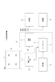
- FIG. 1 shows the configuration of an image processing apparatus 1 that performs image data encoding processing.
- the image processing device 1 includes, for example, an encoding device 10, a storage unit 13, a communication unit 14, an operation unit 15, and an image source 16.
- the encoding device 10 is composed of a compression encoder 11 and a controller 12.
- the image source 16 indicates a part that supplies the image data IDT (moving image or still image) to be processed in the encoding process to the encoding device 10.
- a storage device that stores the image data IDT in the image processing device 1 is an example of the image source 16.
- a receiving device for image data transmitted from an external device in a wired or wireless manner is also an example of the image source 16.
- a reproducing device that reads out the image data IDT from a storage medium such as a memory card, an optical disk, or a magnetic tape, an HDD (Hard Disk Drive), or the like is also an example of the image source 16.
- the image data IDT from the image source 16 is supplied to the compression encoder 11, and the compression encoder 11 performs image compression encoding.
- the compression encoder 11 performs image compression encoding.
- FIG. 2 shows a configuration example of the compression encoder 11 in the case of performing compression encoding of the JPEG2000 standard.
- the input image data IDT is wavelet-transformed by the wavelet transform unit 31, and is input to an EBCOT (Embedded Block Coding with Optimal Truncation) 33 through the quantization processing in the quantization unit 32.
- the EBCOT 33 has a configuration as a bit plane encoder 35 and an arithmetic encoder 36. With this configuration, the wavelet-transformed data is quantized and then subjected to entropy coding by the EBCOT 33. That is, the EBCOT 33 performs encoding in code block units, which are rectangular areas defined on the wavelet transform coefficients. Each code block is decomposed into bit planes by the bit plane encoder 35, and classified into three encoding passes by the coefficient bit modeling processing. Then, compression processing is performed by the arithmetic encoder 36 for each encoding pass.
- the compression encoder 11 is provided with a configuration as the rate controller 34, and the quantization unit 32 and the EBCOT 33 are controlled by the rate controller 34, whereby the compression rate can be set for each data unit of the compression process.
- the controller 12 instructing the rate controller 34 of the information of the rate control area and the compression rate
- the rate controller 34 accordingly instructs the quantization section 32 and the EBCOT 33 to perform necessary compression processing. Will be executed.
- the above is merely an example of the compression encoder 11, and, for example, MPEG4, H.264 or the like.
- the configuration when another compression method such as H.264 / MPEG-4 AVC or JPEG is adopted is different.
- the compressed image data cIDT compression-coded by such a compression encoder 11 is supplied to the storage unit 13 of FIG. 1 and stored in the storage medium.
- the compressed image data cIDT compressed and encoded by the compression encoder 11 can be transmitted to the external device by the communication unit 14.
- the recording unit 13 may be a flash memory built in the image processing apparatus 1, or may be a removable memory card (for example, a portable flash memory) and a card recording / reproducing unit that performs recording / reproducing access to the memory card. It may be in the form. Further, it may be realized as an HDD or the like as a form built in the main body 2.
- the communication unit 14 performs wired or wireless data communication or network communication with an external device, and performs image data communication with an external display device, recording device, reproducing device, or the like, for example. Further, the communication unit 14 as a network communication unit performs communication by various networks such as the Internet, home network, LAN (Local Area Network), etc., and transmits various data to and from servers, terminals, cloud servers, etc. on the network. Transmission and reception may be performed.
- networks such as the Internet, home network, LAN (Local Area Network), etc.
- the controller 12 is composed of, for example, a microcomputer (arithmetic processing device) including a CPU (Central Processing Unit), a ROM (Read Only Memory), a RAM (Random Access Memory), a flash memory, and the like.
- the CPU executes the program stored in the ROM or the flash memory to control the compression encoding process.
- the RAM is used as a work area when the CPU processes various data, and is used for temporarily storing data, programs, and the like.
- the ROM and flash memory are used to store an OS (Operating System) for the CPU to control each unit, various processing parameters, programs for various operations, and the like.
- the controller 12 may perform, for example, division setting of the image data IDT, setting of a rate control area in the image data IDT, and instruction of a rate control area and a compression rate to the compression encoder 11. Based on these controls, as will be described later, the compression encoding process is performed so that the bit rate of the rate control area in the image data IDT is higher than that of areas other than the rate control area.
- the rate control area is an area in the vicinity of the division boundary when the image data is divided into a plurality of areas, and may be fixedly set or set by the controller 12, for example. A specific example of the rate control area will be described later.
- the controller 12 acquires and analyzes the image data IDT of the image source 16, and sets the division of the image data IDT according to the analysis result of the image data IDT, the setting of the rate control area in the image data IDT, and the rate for the compression encoder 11. It is assumed that the control area and compression rate are specified.
- the operation unit 15 collectively shows an operation device for inputting an operation of a user who uses the image processing apparatus 1.
- the user can perform various operation inputs, and the controller 12 can execute processing according to the operation.
- the controller 12 performs the division setting of the image data IDT, the setting of the rate control area in the image data IDT, the instruction of the rate control area and the compression rate to the compression encoder 11 according to these user operations.
- the image data IDT forming one image as a still image or a moving image is compression-encoded, but at the stage of being processed by the storage unit 13 or the communication unit 14, a plurality of divided areas It is supposed to be treated as image data divided into.
- the image data IDT of FIG. 1 is divided into four divided image data PP1, PP2, PP3, PP4, and compressed image data cPP1, cPP2, cPP3 corresponding to these divided image data PP1, PP2, PP3, PP4.
- CPP4 are stored in the storage unit 13 or transmitted from the communication unit 14 to an external device.
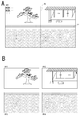
- FIG. 3A shows an example of image data IDT that constitutes one image.
- the image data is 8K ⁇ 4K, and is composed of 8K (7680 pixels) in the horizontal direction and 4K (3840 pixels) in the vertical direction.
- FIG. 3B shows images of the four pieces of divided image data PP1, PP2, PP3, PP4.
- These divided image data PP1, PP2, PP3, PP4 are 4K ⁇ 2K, and are configured by 4K (3840 pixels) in the horizontal direction and 2K (1920 pixels) in the vertical direction.
- compressed image data cIDT (cPP1, cPP2, cPP3, cPP4) that is compression-encoded with respect to 4K ⁇ 2K divided image data PP1, PP2, PP3, PP4 in this way, 4K which is popular at the time of decoding
- a ⁇ 2K compatible decoder can be used.
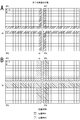
- a configuration example of the image processing device 2 that inputs the compressed image data cIDT (for example, four compressed image data cPP1, cPP2, cPP3, cPP4) compressed and encoded by the above image processing device 1 and decodes the image for image display. Is shown in FIG. 4A.
- the image processing device 2 has a decoding device 20, a display unit 26, and an image source 27.
- the decoding device 20 is composed of four decoders 21, 22, 23, 24 and a display controller 25.
- the image source 27 indicates a portion that supplies the compressed image data cIDT to be processed in the decoding process to the decoding device 20.
- a storage device that stores the compressed image data cIDT in the image processing device 2 is an example of the image source 27.
- a receiving device for image data transmitted from an external device in a wired or wireless manner is also an example of the image source 27.
- a reproducing device that reads out the image data IDT from a storage medium such as a memory card, an optical disk, or a magnetic tape, an HDD (Hard Disk Drive), or the like is also an example of the image source 27.
- the image source 27 supplies, for example, the compressed image data cPP1, cPP2, cPP3, cPP4 divided into four to the four decoders 21, 22, 23 and 24 in parallel, respectively.
- the decoders 21, 22, 23, 24 are decoders corresponding to 4K ⁇ 2K, for example, according to the JPEG2000 standard. Corresponding decryption is performed. Of course, this is just an example, and it goes without saying that the decoder is compatible with encoding.
- the compressed image data cPP1, cPP2, cPP3, and cPP4 are decompressed and decoded in a one-to-one correspondence, and the divided image data PP1, PP2, PP3 as the decoding result are obtained.
- PP4 is obtained.
- the divided image data PP1, PP2, PP3, PP4 are supplied to the display controller 25.
- the display controller 25 synthesizes the divided image data PP1, PP2, PP3, PP4 to generate the original image data IDT, and drives the display of the display unit 26 based on the image data IDT. As a result, the display unit 26 displays the image of the original image data IDT that is obtained by combining the divided image data PP1, PP2, PP3, PP4 as shown in FIG. 4B.
- the display unit 26 is assumed to be a display device using self-luminous elements such as LEDs as pixels.
- the display device is not limited to the LED, and may be another display device such as a display using an organic EL element.
- these self-luminous display devices such as a tiling display, are assumed to be display devices in which units of predetermined pixel units are arranged in a tile shape to form a screen.
- the display device is assumed to be a display device that does not perform overlap display such as that performed by a projector in a joint portion of images.
- the image processing device 1 divides the original image data IDT to generate compressed image data cIDT (cPP1, cPP2, cPP3, cPP4) for each divided area. Further, the image processing device 2 (decoding device 20) decodes the compressed image data cIDT (cPP1, cPP2, cPP3, cPP4), combines them, and displays them.
- a reproduction system can be formed by using, for example, a 4K ⁇ 2K decoder.
- the joint portion of the image that is, the portion of the division boundary dv
- the image quality may deteriorate.
- the compression error increases as the compression rate is increased and the bit rate is decreased, and in the vicinity of the division boundary dv, the error in the divided area of one image and the other divided area. It is considered that the error in 1 is synergistic and a large difference occurs on the image.
- the joints are more conspicuous than in a complicated image in which brightness and color change greatly. It becomes easier.
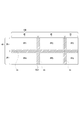
- FIG. 5 shows an example of the rate control area.
- FIG. 5 shows divided image data PP1, PP2, PP3, PP4 divided at the division boundary dv.
- One block separated by a line is a block BK.
- the block BK is a unit of compression processing and is, for example, 8 ⁇ 8 pixels. This is an example, and the block BK as a unit of compression processing may be 2 ⁇ 2 pixels, 4 ⁇ 4 pixels, 16 ⁇ 16 pixels, or the like.
- the range of the block BK hatched is the rate control area.
- the range of the upper and lower one-row blocks BK along the horizontal division boundary dv and the left and right one-column blocks BK along the vertical division boundary dv is the range of the rate control area.
- the areas other than the rate control area are called "normal processing areas”.
- the range of the block BK without the hatched portion is the normal processing area.
- "row" or “column” refers to a horizontal arrangement of blocks BK or a vertical arrangement.
- the normal processing area is compression-encoded at the compression rate RN
- the rate control area is compression-encoded at the compression rate R1.
- RN > R1.
- the compression rate RN may be considered as the compression rate that is originally applied to the entire image. That is, by compressing and coding the normal processing area at the compression rate RN, the purpose of compression is to suppress the bit rate to some extent, but for the rate control area, compression coding is performed at the compression rate R1 lower than the compression rate RN. By doing so, the bit rate is made higher than the normal processing area. As a result, the compression error is suppressed at the division boundary dv. By suppressing the compression error in each block BK of the rate control area that is in contact with the division boundary dv, it is possible to solve the problem that the joints are conspicuous due to the overlap of the errors when they are combined and displayed.
- FIG. 6 shows a processing example of the controller 12 that causes the compression encoder 11 to execute such encoding processing.
- the state of the image data is schematically shown on the right side of each step.
- the controller 12 identifies the image data IDT to be processed in step S101. That is, the image data IDT to be transferred from the image source 16 to the compression encoder 11 is specified.
- step S102 the controller 12 makes division settings for the image data IDT to be processed. That is, the division boundary dv is set so that the division area dv can be divided.
- step S103 the controller 12 sets the rate control area RCA (hatched portion) based on the division boundary dv. For example, as shown in FIG. 5, the range of a block in one row and one column in contact with the division boundary dv is set as a rate control area RCA.
- step S104 the controller 12 causes the compression encoder 11 to perform compression encoding on the image data IDT.
- the controller 12 notifies the compression encoder 11 of the block BK corresponding to the rate control area RCA, and compression-encodes the block BK of the normal processing area at the compression rate RN to obtain the block corresponding to the rate control area RCA.
- the compression encoder 11 is instructed to perform compression encoding at the compression rate R1.
- the rate controller 34 receives this instruction, and the quantizing unit 32 and the EBCOT 33 execute the compression encoding of the compression rate according to the instruction for each block.
- the controller 12 divides the image at the division boundary dv in step S105, and stores the compressed image data cIDT (for example, the compressed image data cPP1, cPP2, cPP3, cPP4) of each divided image in the storage unit. 13 or the communication unit 14 controls to be transmitted to an external device.
- the compressed image data cIDT having a high bit rate is obtained in the rate control area RCA.
- Such compressed image data cIDT is decoded and synthesized by the image processing device 2 having the configuration of FIG. 4, for example, and the image of the original image data IDT is displayed. At this time, the conspicuous joint at the division boundary dv is resolved.
- FIG. 7 shows a processing example of the controller 12 as the second embodiment. Also in FIG. 7, the state of the image data is schematically shown on the right side of each step.
- the controller 12 identifies the image data IDT to be processed in step S101. Then, in step S102, the controller 12 performs division setting for the image data IDT to be processed. That is, the division boundary dv is set so that the division area dv can be divided. The above is the same as in FIG.
- the controller 12 performs image division in step S110. That is, the controller 12 divides the image data IDT based on the division boundary dv to form divided image data PP1, PP2, PP3, PP4 for each divided area.
- the controller 12 sets the rate control area RCA (hatched portion) based on the division boundary dv.
- the rate control area RCA hatchched portion
- step S112 the controller 12 causes the compression encoder 11 to sequentially perform compression encoding on the divided image data PP1, PP2, PP3, PP4.
- the controller 12 notifies the rate control area RCA for each of the divided image data PP1, PP2, PP3, PP4, and performs compression encoding of the block BK in the normal processing area at the compression rate RN to obtain the rate control area RCA.
- the compression encoder 11 is instructed to perform compression encoding at the compression rate R1. Further, the controller 12 instructs the compression encoder 11 to transfer the compressed image data cIDT (cPP1, cPP2, cPP3, cPP4) to the storage unit 13 or the communication unit 14 according to the completion of the compression process.
- the compression encoder 11 under the control of the rate controller 34, for example, when the divided image data PP1 is compressed, the compression processing is performed so that the compression rate becomes low for the block BK of the rate control area RCA for the divided image data PP1. become. Then, the compressed image data cPP1 is transferred to and stored in the storage unit 13. Alternatively, it is transferred to the communication unit 14 and transmitted to an external device. Such processing is sequentially performed on the divided image data PP2, PP3, PP4.
- the compressed image data cIDT (cPP1, cPP2, cPP3, cPP4) whose bit rate is increased in the rate control area RCA is obtained.
- Such compressed image data cIDT is decoded and synthesized by the image processing device 2 having the configuration of FIG. 4, for example, and the image of the original image data IDT is displayed. At this time, the conspicuous joint at the division boundary dv is resolved.
- FIG. 8 shows the rate control area of the third embodiment.
- FIG. 8 shows a plurality of block rows (two rows in each case in this case, two rows in each case) continuous from a row of blocks (horizontal arrangement of blocks BK) in contact with the horizontal division boundary dv, and a block in contact with the vertical division boundary dv.
- a range of a plurality of block columns two columns each on the left and right in this case
- a column a vertical arrangement of blocks BK
- the rate control area may be set in a range of a plurality of rows and a plurality of columns as seen from the division boundary dv as shown in 2 rows and 2 columns in FIG.
- 2 rows and 2 columns is an example, and 3 rows and 3 columns, 4 rows and 4 columns, or more rows and columns can be considered.
- the rate control area of the fourth embodiment is shown in FIG. Also in FIG. 9, a plurality of block rows continuous from the row of blocks contacting the horizontal division boundary dv (two rows in each case, upper and lower in this case), and a plurality of block columns continuous from the column of blocks contacting the vertical division boundary dv ( In this case, the range of the left and right two columns) is set as the rate control area.
- areas having different compression rates are set.
- the block BK which is in contact with the division boundary dv is an area having a compression rate R1
- the block BK which is not in contact with the division boundary dv and which is the second row or the second column from the division boundary dv is an area having a compression rate R2.
- the block BK closest to the division boundary dv has a high bit rate, and the bit rate decreases as the distance from the division boundary dv increases.
- the compression rate is set to two stages of the compression rates R1 and R2, but the compression rate is set to three stages and four stages, and the bit rate increases as the distance from the division boundary dv increases in more stages. It can also be set to lower.
- the block of 6 rows and 6 columns is set as the rate control area, and the compression rate is gradually increased to R1, R2, R3 (however, RN>R3>R2> R1) every 2 rows and 2 columns as the distance from the division boundary dv increases. May be.
- the variation width of the compression rate, the number of stages, and the number of rows / columns of each compression rate can be variously considered.
- the bit rate is gradually increased toward the division boundary dv, but this is also effective in making the joints of the images inconspicuous.
- the controller 12 informs the compression encoder 11 of the compression ratios R1, R2, ...
- the block BK, the block BK of the compression rate R2, ... Are designated.
- the rate control area of the fifth embodiment is shown in FIGS. 10A and 10B.
- FIG. 10A shows the compression rate R1 for the block BK in the rate control area
- FIG. 10B shows the compression rate R2 for the block BK in the same rate control area.
- the controller 12 does not change the setting of the rate control area, but changes the compression rate applied to the rate control area.
- the controller 12 analyzes the image data IDT, and particularly determines the change tendency of the brightness and color around the division boundary dv.
- a relatively high compression rate R2 lower bit rate
- FIG. 10B a relatively high compression rate
- R1 higher bit rate
- the compression rate of the rate control area may be variably set according to the required data size. If the data size is required to be as small as possible, a relatively high compression rate R2 (lower bit rate) is selected as shown in FIG. 10B.
- the controller 12 selects the compression rate of the rate control area according to the user operation. For example, the user gives an instruction as to whether it is desirable to eliminate the problem of joints or reduce the amount of data. The controller 12 selects the compression rate accordingly.
- rate control area may be variably set not only in two stages of compression rates R1 and R2 but also in three stages or more.
- the rate control area of the sixth embodiment is shown in FIGS. 11A and 11B.
- This is an example in which the range of the rate control area is switched as shown in FIGS. 11A and 11B, for example.
- FIG. 11A one row and one column from the division boundary dv is used as a rate control area.
- FIG. 11B 2 rows and 2 columns from the division boundary dv are used as the rate control area.
- the controller 12 variably sets the range of the rate control area according to the image analysis result of the image data IDT or the user operation.
- FIG. 11B is more advantageous than FIG. 11A in eliminating the problem of joints, while FIG. 11A is more advantageous in reducing the amount of data than FIG. 11B.
- the 1st row and 1st column and the 2nd row and 2nd column are selected for the rate control area, this is an example.
- an example in which 2 rows and 2 columns and 5 rows and 5 columns are selected can be considered.
- the range of the rate control area may be selected in more stages. For example, it is possible to select 2 rows, 2 columns, 5 rows, 5 columns, and 7 rows and 7 columns.
- the number of selectable matrices is not particularly limited, and the rate control area may be set with an appropriate number of rows and columns according to image analysis, user input, and the like. It is also desirable to change the range as the rate control area, for example, according to the image content. For example, it is conceivable to set the number of rows and the number of columns according to the range of the smooth image content near the division boundary dv.
- the rate control area of the seventh embodiment is shown in FIGS. 12A and 12B.
- FIG. 12A is an example in which the 1st row and 1st column from the division boundary dv is the rate control area and the compression rate is R1.
- FIG. 12B is an example in which 2 rows and 2 columns from the division boundary dv are set as the rate control area and the compression rate is set as R2.
- the controller 12 variably sets the range of the rate control area and the compression rate according to the image analysis result of the image data IDT and the user operation. This enables compression encoding according to the image content and the purpose of processing.
- the rate control area of the eighth embodiment is shown in FIGS. 13A and 13B. This is also an example in which the range of the rate control area is switched, for example, as shown in FIGS. 13A and 13B.
- the rate control area is divided into two rows from the horizontal division boundary dv and one column from the vertical division boundary dv. I am trying.
- FIG. 13B one row from the horizontal division boundary dv and two columns from the vertical division boundary dv are used as the rate control area. That is, the range of the rate control area in the horizontal direction and the vertical direction is changed.
- FIG. 13A is effective in the case of an image in which horizontal seams are conspicuous.
- reducing the number of columns in the rate control area contributes to the reduction of the data amount.
- 13B is effective in the case of an image in which vertical seams are conspicuous. In this case, reducing the number of rows in the rate control area contributes to the reduction of the data amount.
- the rate control area for eliminating the joint is wide in the horizontal direction or the vertical direction depending on the image content, it is possible to eliminate the joint margin and reduce the data amount. Further, further advancing this idea, it is possible to consider that the rate control area is limited to only the block rows along the horizontal division boundary dv, or conversely only to the block columns along the vertical division boundary dv.
- the rate control area of the ninth embodiment is shown in FIGS. 14A and 14B. This is an example of switching the compression rate of the rate control area.
- the block BK along the horizontal division boundary dv has a compression rate R2
- the block BK along the vertical division boundary dv has a compression rate R1.
- the block BK along the horizontal division boundary dv has a compression rate R1
- the block BK along the vertical division boundary dv has a compression rate R2.
- the compression ratios R1 and R2 can be considered for the block BK of the corner portion that follows both the horizontal and vertical division boundaries dv, but it is low because the connection points are concentrated.
- the bit rate may be increased as the compression rate R1.
- FIG. 14B is effective in the case of an image in which horizontal joints are conspicuous
- FIG. 14A is effective in the case of an image in which vertical joints are conspicuous.
- increasing the compression rate of the other contributes to the reduction of the data amount.
- FIGS. 13A and 13B a combination of the ideas of FIGS. 13A and 13B and the ideas of FIGS. 14A and 14B is also possible. That is, as shown in FIGS. 13A and 13B, the number of rows and columns in the horizontal and vertical directions is switched, and the compression rate is also switched between block rows in the horizontal direction and block columns in the vertical direction. For example, in the rate control area, if there are two rows and one column, the row compression rate R1 and the column compression rate R2 are set. In other cases, the one row and two columns row compression rate R2 and the column compression rate R1 are set. And so on. Of course, it may be possible to switch to more stages.
- rate control areas of various embodiments and their modifications have been described above, various setting examples of the rate control areas can be considered.
- a combination of a plurality of examples among the examples of FIGS. 5, 8, 9, 10A, 10B, 11A, 11B, 12A, 12B, 13A, 13B, 14A, and 14B is also possible.
- Various types are assumed.
- Each of these examples can also be applied to the case where the setting of the rate control area and the compression rate are switched according to the image content, user input, and the like.
- the rate control area is set in the same manner (by the same rule) in each of the divided image data PP1, PP2, PP3, PP4, but the range of the rate control area and the compression rate are mutually different. It may be different.
- the rate control area is set to 1 row and 1 column, and in the divided image data PP3, the rate control area is set to 2 row and 1 column.
- the rate control area may be set to the compression ratio R1 in the first row and the first column, and in the divided image data PP3, the rate control area may be set to the second row and the first column in the compression ratio R2.
- FIG. 15 exemplifies image data having a size of 10K ⁇ 4K.
- a division boundary dv for dividing this into divided image data PP1, PP2, PP3, PP4, PP5, PP6 is set.
- the divided image data PP1, PP2, PP4, PP5 are 4K ⁇ 2K image data
- the divided image data PP3, PP6 are 2K ⁇ 2K image data.
- the rate control area RCA indicated by the shaded area is set, and the compression rate is lowered and the bit rate is increased in that range, so that the joint is displayed when decoding and displaying. Can be eliminated.
- the encoding device 10 includes a compression encoder 11 (encoding processing unit) that performs an encoding process on image data to be processed, and a vicinity of a division boundary when the image data to be processed is divided into a plurality of regions.
- the controller 12 controls the encoding process so that the bit rate is higher than that of the area other than the rate control area (normal processing area).
- the data amount forming the rate control area has a larger amount of information than the normal processing area in the image.
- a high-quality image can be displayed in an image processing system that divides an image and encodes and decodes it. It is particularly suitable for large-screen display on a self-luminous display device such as an LED display.
- the compression encoder 11 performs the compression encoding process, but the controller 12 instructs the compression encoding process at the compression rate lower than the compression rate for the normal processing area for the rate control area.
- the controller 12 instructs the compression encoding process at the compression rate lower than the compression rate for the normal processing area for the rate control area.
- the data in the rate control area near the division boundary is compressed at a low compression rate to increase the bit rate.
- the normal processing area is compressed at a relatively high compression rate RN, and the rate control area is compressed at a relatively low compression rate R1 or R2. This increases the bit rate of image data in the rate control area as the amount of data after compression.
- the compression error becomes conspicuous, and the error spreads in the vicinity of the division boundary, causing a phenomenon that the seam is visible.
- the compression rate is reduced to increase the data amount and reduce the compression error. As a result, it is possible to avoid the phenomenon that the joint is conspicuous in the display image after decoding / combining.
- the controller 12 performs the control process as shown in FIG. 6 or 7 in the embodiment, the rate controller 34 in the compression encoder 11 may perform the process.
- the controller 12 performs processing for setting the rate control area based on the division boundary of the image data to be processed. (S103, S111).
- the rate control area may be regularly set from the division boundary dv to blocks of the number of x rows or the number of y columns, or may be variably set according to a user operation or image content.
- the rate control area may be fixedly set according to the image size, the size of the block BK, and the like.
- the controller 12 sets the division boundary dv of the image data to be processed (S102 in FIG. 6), sets the rate control area based on the division boundary (S103), and regarding the rate control area,
- the compression encoder 11 is made to execute the encoding process for the image data IDT to be processed by instructing the bit rate to be higher than the normal processing area (S104). That is, the division boundary dv is set to set the rate control area, and then the rate control area is instructed to execute the encoding process.
- compression encoding is performed so that the compression rate is different in the rate control area.
- division boundaries can be set according to the decoding system and display system devices and circuit configurations, and in that case, the rate control area can be set appropriately. Can be set.
- the controller 12 has described an example in which the encoded image data is controlled to be treated as a plurality of image data divided at the set division boundary (FIG. 6). S105). That is, after the original image data IDT is entirely compressed, the plurality of divided compressed image data cIDTs (for example, compressed image data cPP1, cPP2, cPP3, cPP4) are stored and transmitted. As a result, the compressed image data cIDT of a plurality of divided areas joined at the time of decoding is prepared. The compressed image data cIDT has a high bit rate in the image data near the boundary to be joined.
- the controller 12 sets the division boundary dv of the image data IDT to be processed (S102 of FIG. 7), divides the image data based on the division boundary (S110), and divides each divided area.
- An example has been described in which the rate control area is set (S111) and the encoding process is executed by the compression encoder 11 (S112). Even in such processing, compression encoding is performed so that the compression rate is different in the rate control area. Also in this case, since the original image data can be arbitrarily divided into regions, division boundaries can be set according to the decoding system and display system devices and circuit configurations, and in that case, appropriate rate control can be performed. Area can be set.
- the rate control area when the block BK made up of a plurality of pixel data is used as an encoding processing unit, the rate control area includes at least the block BK in contact with the division boundary. did. That is, the row or column of the block BK whose one side forms the division boundary is included in the rate control area.
- FIG. 5 FIG. 8, FIG. 9, FIG. 10A, FIG. 10B, FIG. 11A, FIG. 11B, FIG. 12A, FIG. 12B, FIG. 13A, FIG. 13B, FIG. 14A, and FIG. BK (hatched portion) is a rate control area.
- At least the block BK which is in contact with the division boundary is included in the rate control area and has a high bit rate, which is effective in preventing the conspicuous joint at the time of display after decoding. It should be noted that minimizing the rate control area for increasing the bit rate as shown in FIG. 5 is suitable for reducing the data amount.
- a plurality of block rows continuous from a row of blocks in contact with the division boundary or continuous columns of blocks in contact with the division boundary is shown. That is, it is assumed that at least a row or a column of a block that is in contact with a division boundary is set as a rate control area over a plurality of rows or columns, and those blocks may have a high bit rate. For example, in the example of FIGS.
- a plurality of rows or columns consecutive from the row or column of the block BK (hatched portion) in contact with the division boundary dv is the rate control area. There is. By increasing the bit rate by setting a certain range near the division boundary as the rate control area, it is effective to prevent the conspicuous joint at the time of display after decoding.
- the controller 12 causes the block BK in which the compression coding of the compression ratio R1 is performed and the block BK in which the compression coding of the compression ratio R2 is performed in the rate control area.
- the example in which the control is performed is described (see FIGS. 9, 14A, and 14B). That is, in the block BK corresponding to the rate control area, there is a block BK for which compression encoding with a different compression rate is instructed.
- compression encoding is performed such that the bit rate gradually increases toward the division boundary as shown in FIG. This is also effective in preventing conspicuous joints in the display after decoding.
- FIGS. 14A and 14B the compression rate is different between the blocks in the vertical direction and the horizontal direction, so that adaptive compression encoding according to the image is performed. As a result, there are cases where it is possible to meet the demands for higher image quality and data volume reduction.
- the controller 12 variably sets the blocks corresponding to the rate control area. That is, the rate control area is not fixedly set, but the rate control area is variably set by a predetermined algorithm. For example, as in the examples described in FIGS. 11A and 11B, 12A and 12B, or 13A and 13B, the setting of the block BK that is the rate control area can be changed according to the analysis result of the image content. Alternatively, it is made variable according to a user operation. As a result, the rate control area is adaptively set according to the situation and compression coding is performed. Depending on the image contents, the joints may not be noticeable without widening the rate control area.
- the controller 12 variably sets the compression rate instructing the compression encoder 11 for the rate control area. That is, the compression rate of the rate control area is not fixedly set, but is set variably by a predetermined algorithm. For example, as in the example described with reference to FIGS. 10A and 10B, the compression rate of the rate control area is made variable according to the analysis result of the image content, or is made variable according to the user operation. As a result, the compression rate is adaptively selected according to the situation and the compression encoding is performed. Depending on the image content, the joint may not be noticeable without reducing the compression rate so much. For such an image, increasing the compression rate of the rate control area is desirable in terms of data amount reduction.
- the number of rows of blocks forming the rate control area is larger than the number of columns of blocks, it is advantageous to eliminate the problem of horizontal joints. Especially when the vertical joints are not noticeable, the number of columns is reduced to reduce the amount of data.
- the compression encoder 11 when the division boundaries exist in the horizontal direction and the vertical direction of the image data to be processed, the compression encoder 11 is instructed about the blocks along the horizontal division boundaries in the rate control area.
- An example has been described in which the rate and the compression rate instructing the compression encoder 11 for blocks along the vertical division boundary are made different. That is, among the blocks BK forming the rate control area, the horizontal row blocks BK and the vertical row blocks BK have different compression rates.
- the compression rate R1 is set for the blocks BK arranged in the column direction
- the compression rate R2 is set for the blocks BK arranged in the row direction. This is advantageous in eliminating the problem of vertical joints.
- the blocks BK arranged in the row direction have a compression rate R2 higher than the compression rate R1, which is suitable for reducing the amount of data.
- the compression rate R1 is set for the blocks BK arranged in the row direction
- the compression rate R2 is set for the blocks BK arranged in the column direction. This is advantageous in eliminating the problem of horizontal joints.
- the blocks BK arranged in the column direction have a compression rate R2 higher than the compression rate R1, which is suitable for reducing the amount of data. 13A and 13B and the ideas of FIGS.
- compressed image data cIDT (for example, cPP1, cPP2, cPP3, cPP4) is input as a plurality of image data which are a plurality of divided areas forming one image. Each of them is coded so that the rate control area set near the division boundary dv at the time of division has a higher bit rate than the normal processing area.
- a plurality of decoders (decoding processing units) 21, 22, 23, 24 for performing decoding are provided.
- the decoding device 20 synthesizes a plurality of image data (for example, divided image data PP1, PP2, PP3, PP4) decoded by the plurality of decoders 21, 22, 23, 24 as image data forming one image.
- a display controller (display control unit) 25 that executes display is provided.
- the image data of the divided areas of which the bit rate has been increased in the rate control area is decoded, and is combined and displayed so as to be joined at the dividing boundaries. In this case, it is possible to display a high-quality image with no noticeable joint.
- An encoding processing unit that performs an encoding process on the image data to be processed, With respect to the rate control area in the vicinity of the division boundary when the image data to be processed is divided into a plurality of areas, a control unit that controls the encoding processing so that the bit rate is higher than that in areas other than the rate control area. And an encoding device including.
- the encoding processing unit performs compression encoding processing, The encoding device according to (1), wherein, for the rate control area, the control unit instructs a compression encoding process at a compression rate lower than a compression rate of the compression encoding process other than the rate control area.
- the said control part is a coding apparatus as described in said (1) or (2) which performs the process which sets the said rate control area based on the division
- the control unit sets a division boundary of the image data to be processed, and sets the rate control area based on the division boundary, The rate control area is instructed to have a bit rate higher than those of areas other than the rate control area, and the encoding processing unit is caused to execute the encoding processing on the image data to be processed.
- the encoding device according to any one of 1.
- the encoding device controls the image data subjected to the encoding process so as to be treated as a plurality of image data divided at a set division boundary.
- the control unit sets a division boundary of the image data to be processed, divides the image data based on the division boundary, sets the rate control area for each divided area, and performs an encoding process by the encoding processing unit.
- the encoding device according to any one of (1) to (3).
- (7) When a block consisting of multiple pixel data is used as the encoding processing unit, The coding device according to any one of (1) to (6) above, wherein the rate control area includes at least a block in contact with a division boundary.
- the rate control area includes a plurality of block rows continuous from a row of blocks in contact with the division boundary, or a plurality of block columns continuous from a column of blocks in contact with the division boundary in any one of (1) to (6) above. Encoding device described.
- the control unit performs control so that a block in which compression coding of a first compression rate is performed and a block in which compression coding of a second compression rate is performed occur (1) To (8).
- the said control part is a coding device in any one of said (1) to (9) which variably sets the block applicable to the said rate control area.
- the rate control area is set such that the number of block rows along the horizontal division boundary and the number of block columns along the vertical division boundary in the rate control area are different from each other.
- the encoding device When a block consisting of multiple pixel data is used as the encoding processing unit, The rate control area is set such that the number of block rows along the horizontal division boundary and the number of block columns along the vertical division boundary in the rate control area are different from each other.
- the control unit instructs the encoding processing unit about a compression rate for blocks along horizontal division boundaries, and instructs the encoding processing unit for blocks along vertical division boundaries.
- the encoding device according to any one of (1) to (12), wherein the compression rate is set to be different.
- the encoding process is performed so that the bit rate becomes higher in the rate control area near the division boundary when the image data is divided into a plurality of areas. Encoding method.
- a plurality of decoding processing units that perform decoding corresponding to a plurality of image data that have been subjected to encoding processing so that A decoding device, comprising: a display control unit configured to combine a plurality of image data decoded by the plurality of decoding processing units and display the image data as image data forming one image.
Landscapes
- Engineering & Computer Science (AREA)
- Multimedia (AREA)
- Signal Processing (AREA)
- Physics & Mathematics (AREA)
- General Physics & Mathematics (AREA)
- Theoretical Computer Science (AREA)
- Compression Or Coding Systems Of Tv Signals (AREA)
- Compression Of Band Width Or Redundancy In Fax (AREA)
Abstract
Priority Applications (5)
| Application Number | Priority Date | Filing Date | Title |
|---|---|---|---|
| KR1020217010353A KR20210071986A (ko) | 2018-10-18 | 2019-07-16 | 부호화 장치, 부호화 방법, 복호 장치 |
| CN201980066603.2A CN112823516A (zh) | 2018-10-18 | 2019-07-16 | 编码设备、编码方法和解码设备 |
| EP19874304.9A EP3869801A4 (fr) | 2018-10-18 | 2019-07-16 | Dispositif de codage, procédé de codage, et dispositif de décodage |
| US17/277,966 US20210350581A1 (en) | 2018-10-18 | 2019-07-16 | Encoding device, encoding method, and decoding device |
| JP2020552528A JPWO2020079900A1 (ja) | 2018-10-18 | 2019-07-16 | 符号化装置、符号化方法、復号装置 |
Applications Claiming Priority (2)
| Application Number | Priority Date | Filing Date | Title |
|---|---|---|---|
| JP2018196639 | 2018-10-18 | ||
| JP2018-196639 | 2018-10-18 |
Publications (1)
| Publication Number | Publication Date |
|---|---|
| WO2020079900A1 true WO2020079900A1 (fr) | 2020-04-23 |
Family
ID=70284535
Family Applications (1)
| Application Number | Title | Priority Date | Filing Date |
|---|---|---|---|
| PCT/JP2019/027861 Ceased WO2020079900A1 (fr) | 2018-10-18 | 2019-07-16 | Dispositif de codage, procédé de codage, et dispositif de décodage |
Country Status (7)
| Country | Link |
|---|---|
| US (1) | US20210350581A1 (fr) |
| EP (1) | EP3869801A4 (fr) |
| JP (1) | JPWO2020079900A1 (fr) |
| KR (1) | KR20210071986A (fr) |
| CN (1) | CN112823516A (fr) |
| TW (1) | TWI829740B (fr) |
| WO (1) | WO2020079900A1 (fr) |
Citations (9)
| Publication number | Priority date | Publication date | Assignee | Title |
|---|---|---|---|---|
| JPH09275561A (ja) * | 1996-04-08 | 1997-10-21 | Toshiba Corp | 映像圧縮装置及び映像圧縮方法 |
| JP2002374532A (ja) * | 2001-06-13 | 2002-12-26 | Ricoh Co Ltd | 画像圧縮装置、方法、プログラムおよび記録媒体 |
| JP2003204436A (ja) * | 2001-10-29 | 2003-07-18 | Victor Co Of Japan Ltd | 画像符号化装置及び画像符号化プログラム |
| JP2003348597A (ja) * | 2002-05-29 | 2003-12-05 | Sony Corp | 画像符号化装置および画像符号化方法 |
| JP2004064126A (ja) * | 2002-07-24 | 2004-02-26 | Kddi Corp | 画像符号化装置および画像符号化方法、コンピュータプログラム |
| JP2004147143A (ja) | 2002-10-25 | 2004-05-20 | Digital Zuu:Kk | 複数台のプロジェクタによるマルチ映像投影方法、同方法を使用するためのプロジェクタ装置、プログラム及び記録媒体 |
| JP2012120054A (ja) * | 2010-12-02 | 2012-06-21 | Canon Inc | 画像符号化装置、画像符号化方法およびプログラム |
| JP2015171117A (ja) * | 2014-03-11 | 2015-09-28 | キヤノン株式会社 | 画像符号化装置 |
| JP2017116950A (ja) | 2013-07-19 | 2017-06-29 | 株式会社Jvcケンウッド | マルチプロジェクタシステム、プロジェクタ装置、調整装置および調整方法、ならびに、調整プログラム |
Family Cites Families (9)
| Publication number | Priority date | Publication date | Assignee | Title |
|---|---|---|---|---|
| KR100207419B1 (ko) * | 1995-03-20 | 1999-07-15 | 전주범 | 부호화 비트발생율 제어방법 및 그 제어장치 |
| JP2001285876A (ja) * | 2000-03-30 | 2001-10-12 | Sony Corp | 画像符号化装置とその方法、ビデオカメラ、画像記録装置、画像伝送装置 |
| CN1420633A (zh) * | 2001-10-29 | 2003-05-28 | 日本胜利株式会社 | 图像编码装置以及图像编码方法 |
| JP4616057B2 (ja) * | 2005-04-13 | 2011-01-19 | パイオニア株式会社 | 画像符号化装置及び画像符号化方法 |
| JP5914962B2 (ja) * | 2010-04-09 | 2016-05-11 | ソニー株式会社 | 画像処理装置および方法、プログラム、並びに、記録媒体 |
| US20120195369A1 (en) * | 2011-01-28 | 2012-08-02 | Eye IO, LLC | Adaptive bit rate control based on scenes |
| JP6023596B2 (ja) * | 2013-01-24 | 2016-11-09 | 株式会社日立情報通信エンジニアリング | 画像符号化装置 |
| US10205950B2 (en) * | 2014-02-21 | 2019-02-12 | Panasonic Corporation | Image decoding method, image encoding method, image decoding apparatus, and image encoding apparatus |
| US11172208B2 (en) * | 2017-02-28 | 2021-11-09 | Nokia Technologies Oy | Method and apparatus for improving the visual quality of viewport-based omnidirectional video streaming |
-
2019
- 2019-07-16 WO PCT/JP2019/027861 patent/WO2020079900A1/fr not_active Ceased
- 2019-07-16 EP EP19874304.9A patent/EP3869801A4/fr not_active Withdrawn
- 2019-07-16 KR KR1020217010353A patent/KR20210071986A/ko active Pending
- 2019-07-16 US US17/277,966 patent/US20210350581A1/en not_active Abandoned
- 2019-07-16 CN CN201980066603.2A patent/CN112823516A/zh active Pending
- 2019-07-16 JP JP2020552528A patent/JPWO2020079900A1/ja active Pending
- 2019-08-16 TW TW108129193A patent/TWI829740B/zh active
Patent Citations (9)
| Publication number | Priority date | Publication date | Assignee | Title |
|---|---|---|---|---|
| JPH09275561A (ja) * | 1996-04-08 | 1997-10-21 | Toshiba Corp | 映像圧縮装置及び映像圧縮方法 |
| JP2002374532A (ja) * | 2001-06-13 | 2002-12-26 | Ricoh Co Ltd | 画像圧縮装置、方法、プログラムおよび記録媒体 |
| JP2003204436A (ja) * | 2001-10-29 | 2003-07-18 | Victor Co Of Japan Ltd | 画像符号化装置及び画像符号化プログラム |
| JP2003348597A (ja) * | 2002-05-29 | 2003-12-05 | Sony Corp | 画像符号化装置および画像符号化方法 |
| JP2004064126A (ja) * | 2002-07-24 | 2004-02-26 | Kddi Corp | 画像符号化装置および画像符号化方法、コンピュータプログラム |
| JP2004147143A (ja) | 2002-10-25 | 2004-05-20 | Digital Zuu:Kk | 複数台のプロジェクタによるマルチ映像投影方法、同方法を使用するためのプロジェクタ装置、プログラム及び記録媒体 |
| JP2012120054A (ja) * | 2010-12-02 | 2012-06-21 | Canon Inc | 画像符号化装置、画像符号化方法およびプログラム |
| JP2017116950A (ja) | 2013-07-19 | 2017-06-29 | 株式会社Jvcケンウッド | マルチプロジェクタシステム、プロジェクタ装置、調整装置および調整方法、ならびに、調整プログラム |
| JP2015171117A (ja) * | 2014-03-11 | 2015-09-28 | キヤノン株式会社 | 画像符号化装置 |
Non-Patent Citations (1)
| Title |
|---|
| See also references of EP3869801A4 |
Also Published As
| Publication number | Publication date |
|---|---|
| US20210350581A1 (en) | 2021-11-11 |
| JPWO2020079900A1 (ja) | 2021-09-24 |
| TW202029749A (zh) | 2020-08-01 |
| EP3869801A4 (fr) | 2021-12-08 |
| EP3869801A1 (fr) | 2021-08-25 |
| KR20210071986A (ko) | 2021-06-16 |
| CN112823516A (zh) | 2021-05-18 |
| TWI829740B (zh) | 2024-01-21 |
Similar Documents
| Publication | Publication Date | Title |
|---|---|---|
| US9681139B2 (en) | Method and apparatus for ROI coding using variable block size coding information | |
| KR101874102B1 (ko) | 영상의 인트라 예측 부호화 방법 및 장치 및 컴퓨터 기록매체 | |
| JP5989934B2 (ja) | マルチレイヤvdr符号化における知覚量子化ビデオコンテンツのエンコーディング | |
| JP4491349B2 (ja) | ビデオ・データのイントラ符号化方法及び装置 | |
| US20160330485A1 (en) | Method and apparatus for encoding/decoding images using a prediction method adopting in-loop filtering | |
| TWI551124B (zh) | 應用於視訊系統之編碼/解碼方法及編碼/解碼裝置 | |
| JP2015522986A (ja) | 層状の時間的階層における時系列および/または多次元信号のデコードおよび再構成 | |
| JP2021523588A (ja) | 四分木二分木のブロック形状適応イントラ予測方向 | |
| CN104410857A (zh) | 一种图像显示控制方法及相关设备 | |
| KR20250157333A (ko) | 고효율 비디오 코딩을 위한 화면 내 예측 방법 및 장치 | |
| KR102401851B1 (ko) | 영상 압축 방법 및 이를 수행하는 표시 장치 | |
| KR20200035380A (ko) | 비트율 제어 방법 및 이의 장치 | |
| JP6194334B2 (ja) | 映像符号化装置、映像符号化方法及び映像符号化プログラム | |
| CN1809166A (zh) | 图像编码和解码装置及其方法 | |
| JPWO2020079900A1 (ja) | 符号化装置、符号化方法、復号装置 | |
| CN110719471B (zh) | 显示系统的压缩方法 | |
| WO2020129498A1 (fr) | Dispositif de codage d'image, procédé de codage d'image, dispositif de décodage d'image et procédé de décodage d'image | |
| US20250373814A1 (en) | Systems and methods of rate control for multiple pass video encoding | |
| CN105323589B (zh) | 应用于视频系统的编码/解码方法及编码/解码装置 | |
| JP4331992B2 (ja) | 画像符号化方法,画像復号方法,画像符号化装置,画像復号装置,それらのプログラムおよびそれらのプログラム記録媒体 | |
| JP2010141775A (ja) | 表示装置駆動回路及び表示装置 | |
| Shirani et al. | Application of nonlinear pre-and post-processing in low bit rate, error resilient image communication | |
| WO2023181546A1 (fr) | Dispositif de codage d'images, dispositif de décodage d'images, procédé de codage d'images et procédé de décodage d'images | |
| US20190014324A1 (en) | Method and system for intra prediction in image encoding | |
| JP2011155426A (ja) | 画像符号化装置及び画像符号化方法 |
Legal Events
| Date | Code | Title | Description |
|---|---|---|---|
| 121 | Ep: the epo has been informed by wipo that ep was designated in this application |
Ref document number: 19874304 Country of ref document: EP Kind code of ref document: A1 |
|
| ENP | Entry into the national phase |
Ref document number: 2020552528 Country of ref document: JP Kind code of ref document: A |
|
| NENP | Non-entry into the national phase |
Ref country code: DE |
|
| ENP | Entry into the national phase |
Ref document number: 2019874304 Country of ref document: EP Effective date: 20210518 |
|
| WWW | Wipo information: withdrawn in national office |
Ref document number: 2019874304 Country of ref document: EP |
|
| WWW | Wipo information: withdrawn in national office |
Ref document number: 1020217010353 Country of ref document: KR |