WO2020079906A1 - ヘッドマウントディスプレイおよびこれに用いられる広焦点レンズの設計方法 - Google Patents
ヘッドマウントディスプレイおよびこれに用いられる広焦点レンズの設計方法 Download PDFInfo
- Publication number
- WO2020079906A1 WO2020079906A1 PCT/JP2019/028635 JP2019028635W WO2020079906A1 WO 2020079906 A1 WO2020079906 A1 WO 2020079906A1 JP 2019028635 W JP2019028635 W JP 2019028635W WO 2020079906 A1 WO2020079906 A1 WO 2020079906A1
- Authority
- WO
- WIPO (PCT)
- Prior art keywords
- eye
- wide
- virtual image
- lens
- image forming
- Prior art date
- Legal status (The legal status is an assumption and is not a legal conclusion. Google has not performed a legal analysis and makes no representation as to the accuracy of the status listed.)
- Ceased
Links
Images




Classifications
-
- G—PHYSICS
- G02—OPTICS
- G02B—OPTICAL ELEMENTS, SYSTEMS OR APPARATUS
- G02B27/00—Optical systems or apparatus not provided for by any of the groups G02B1/00 - G02B26/00, G02B30/00
- G02B27/01—Head-up displays
- G02B27/017—Head mounted
- G02B27/0172—Head mounted characterised by optical features
-
- G—PHYSICS
- G02—OPTICS
- G02B—OPTICAL ELEMENTS, SYSTEMS OR APPARATUS
- G02B25/00—Eyepieces; Magnifying glasses
- G02B25/001—Eyepieces
-
- G—PHYSICS
- G02—OPTICS
- G02B—OPTICAL ELEMENTS, SYSTEMS OR APPARATUS
- G02B27/00—Optical systems or apparatus not provided for by any of the groups G02B1/00 - G02B26/00, G02B30/00
- G02B27/0012—Optical design, e.g. procedures, algorithms, optimisation routines
-
- G—PHYSICS
- G02—OPTICS
- G02B—OPTICAL ELEMENTS, SYSTEMS OR APPARATUS
- G02B27/00—Optical systems or apparatus not provided for by any of the groups G02B1/00 - G02B26/00, G02B30/00
- G02B27/0075—Optical systems or apparatus not provided for by any of the groups G02B1/00 - G02B26/00, G02B30/00 with means for altering, e.g. increasing, the depth of field or depth of focus
-
- G—PHYSICS
- G02—OPTICS
- G02B—OPTICAL ELEMENTS, SYSTEMS OR APPARATUS
- G02B3/00—Simple or compound lenses
- G02B3/02—Simple or compound lenses with non-spherical faces
-
- G—PHYSICS
- G02—OPTICS
- G02C—SPECTACLES; SUNGLASSES OR GOGGLES INSOFAR AS THEY HAVE THE SAME FEATURES AS SPECTACLES; CONTACT LENSES
- G02C11/00—Non-optical adjuncts; Attachment thereof
- G02C11/10—Electronic devices other than hearing aids
-
- G—PHYSICS
- G02—OPTICS
- G02C—SPECTACLES; SUNGLASSES OR GOGGLES INSOFAR AS THEY HAVE THE SAME FEATURES AS SPECTACLES; CONTACT LENSES
- G02C7/00—Optical parts
- G02C7/02—Lenses; Lens systems ; Methods of designing lenses
- G02C7/022—Ophthalmic lenses having special refractive features achieved by special materials or material structures
-
- G—PHYSICS
- G02—OPTICS
- G02B—OPTICAL ELEMENTS, SYSTEMS OR APPARATUS
- G02B3/00—Simple or compound lenses
- G02B2003/0093—Simple or compound lenses characterised by the shape
-
- G—PHYSICS
- G02—OPTICS
- G02B—OPTICAL ELEMENTS, SYSTEMS OR APPARATUS
- G02B27/00—Optical systems or apparatus not provided for by any of the groups G02B1/00 - G02B26/00, G02B30/00
- G02B27/01—Head-up displays
- G02B27/0101—Head-up displays characterised by optical features
- G02B2027/0132—Head-up displays characterised by optical features comprising binocular systems
-
- G—PHYSICS
- G02—OPTICS
- G02B—OPTICAL ELEMENTS, SYSTEMS OR APPARATUS
- G02B27/00—Optical systems or apparatus not provided for by any of the groups G02B1/00 - G02B26/00, G02B30/00
- G02B27/01—Head-up displays
- G02B27/017—Head mounted
- G02B27/0172—Head mounted characterised by optical features
- G02B2027/0174—Head mounted characterised by optical features holographic
-
- G—PHYSICS
- G02—OPTICS
- G02C—SPECTACLES; SUNGLASSES OR GOGGLES INSOFAR AS THEY HAVE THE SAME FEATURES AS SPECTACLES; CONTACT LENSES
- G02C2202/00—Generic optical aspects applicable to one or more of the subgroups of G02C7/00
- G02C2202/24—Myopia progression prevention
Definitions
- the present invention relates to a head mounted display and a design method of a wide focus lens used for the head mounted display.
- a head-mounted display which is a display device worn on the head, displays a stereoscopic image to a user by displaying parallax images corresponding to the left and right eyes on the display.
- a stereoscopic display method of displaying parallax images corresponding to the left and right eyes in this manner is called twin-eye stereoscopic display.
- the HMD can give a high immersive feeling to the user by displaying a wide-angle stereoscopic image with a particularly large angle of view.
- both eyes rotate to capture the stereoscopic image to correctly perceive the depth of the stereoscopic image due to convergence, while the binocular focus is adjusted by being adjusted to the display that displays the parallax image.
- the depth of a stereoscopic image cannot be perceived correctly. Therefore, due to the interaction between the vergence and the accommodation, the vergence accommodation that induces the focus of the eye to the depth perceived by the vergence cannot work for the stereoscopic image by the two-eye stereoscopic display. Thus, it is said that visual fatigue results from the discrepancy between vergence and accommodation.
- a virtual image may be formed at a distance from a few meters ahead to infinity, a stereoscopic image may be displayed in a nearby manual work space, and the stereoscopic image may be interactively operated.
- the contradiction between regulation is more serious.
- Non-Patent Document 1 a virtual image forming system including a variable focal length mirror and a display is provided for each of the left and right eyes, and a virtual image of the display image is formed at a plurality of different depth positions using the variable focal length mirror.
- An HMD is disclosed that enables focusing of the eye on a stereoscopic image by imaging.
- a DMD Digital Micromirror Device
- a display that operates at high speed is required.
- an image processing device is required to generate at high speed an image divided in the depth direction to be displayed on a high speed display.
- Non-Patent Document 2 discloses an HMD that dynamically changes a virtual image forming relationship using a variable focal length lens and a motor in a virtual image forming system including a display, and detects a rotation angle of left and right eyes. It is described that the depth perceived by the convergence is calculated, and the image forming relationship of the image forming system is changed so as to form a virtual image of the image on the display at the depth position.
- the HMD having such a structure requires a means for detecting the rotation angle of the eye.
- the use of a mechanical mechanism including a variable focal length lens and a motor resulting in cost increase and weight increase, becomes a problem.
- the present invention has a simpler configuration and a head-mounted display capable of viewing a stereoscopic image without suffering visual fatigue due to contradiction of convergence adjustment, and a wide-focus lens used for the same. It is intended to provide a design method of.
- a display device for displaying left-eye and right-eye images on a screen, and a left-eye and a right-eye that are respectively arranged for left-eye and right-eye images on the screen
- Virtual image forming optical system and left eye and right eye having a negative focal length and a width, which are respectively arranged to overlap the left eye and right eye virtual image forming optical systems in the respective optical axis directions.
- a wide-focus lens for use in a head-mounted display.
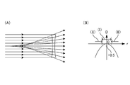
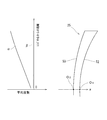
- FIG. 9A is a diagram showing the shape of a wide-focus lens having a negative focal length and a wide width
- FIG. 9B is a diagram showing the distribution of the focal length (refractive power) with respect to the distance from the center. It is the figure which showed the surface shape of the wide focus lens.
- FIG. 6 is a diagram showing a comparative example of the relationship between the angle of the line of sight and the position in the wide-focus lens through which the line of sight passes in a stereoscopic display device having a small angle of view.
- FIG. 7A is a schematic view of an entire wide-focus lens used in the HMD according to the third embodiment
- FIG. 8B is an enlarged view of the upper half of the lens.
- FIG. 3 is a diagram showing a relationship between a line of sight of a user wearing the HMD according to the same embodiment and a wide-focus lens. It is a figure which showed the result of evaluation about the wide-focus lens of FIG. It is the figure which showed the result of the evaluation following FIG.
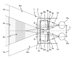
- FIG. 1 shows a schematic configuration of a VR HMD (referred to simply as HMD unless there is confusion) 1 according to the first embodiment.
- the left eye Ea and the right eye Eb of the user are arranged in the vertical direction of the drawing, this direction is the left-right direction, and the left-right direction of the drawing is the front-back direction.
- a reference line extending in the front-rear direction through the centers of the left eye Ea and the right eye Eb is the center line L
- a reference line extending from the left eye Ea and the right eye Eb to the left in the drawing in parallel with the center line L is the main line of sight.
- the separation distance P between the left eye Ea and the right eye Eb of the user is set to be, for example, the average separation distance between the left and right eyes of an adult (typically 65 mm).
- the HMD 1 includes a frame 2, a display device 3, virtual image forming optical systems 4a and 4b for the left and right eyes, wide-focus lenses 5a and 5b for the left and right eyes, and actuators 6a and 6b.
- the frame 2 is a housing that holds the display device 3 and other components of the configuration.
- the shape of the frame 2 is such that the front surface is closed so as to hold the display device 3 inside, the back surface is opened so that the display surface of the display device 3 can be viewed from the back side, and the periphery of both eyes looking into the display device 3 is covered. Any shape may be used as long as the side surface surrounds the front surface.
- a wearing band (not shown) for wearing the HMD 1 in front of the user's face may be provided by connecting the one side of the frame 2 around the occiput of the user to the other side.
- the main lines of sight La and Lb of the left eye Ea and the right eye Eb are overlapped or substantially overlapped with the optical axes of the left and right eye virtual image forming optical systems 4a and 4b, respectively.
- the left-eye and right-eye virtual image forming optical systems 4a and 4b are held in the frame 2.
- the display device 3 is a device that displays left-eye and right-eye images 3a and 3b on the screen 3c.
- a flat panel display such as a liquid crystal display or an organic EL display can be used.
- the display device 3 is held on the back side of the front surface of the frame 2 with the screen 3c facing the back side.
- the screen 3c of the display device 3 includes two regions that are located on the main lines of sight La and Lb of the left eye Ea and the right eye Eb and display the left eye and right eye images 3a and 3b, respectively. Note that, instead of the display device 3 having the single screen 3c, two display devices that respectively display the left-eye and right-eye images 3a and 3b may be used.
- the left-eye and right-eye virtual image forming optical systems (also simply referred to as virtual image forming optical systems) 4a and 4b are used for the left-eye and right-eye images 3a and 3b on the screen 3c of the display device 3. These are optical systems that are respectively arranged and form virtual images of the left-eye and right-eye images 3a and 3b on the virtual image display surfaces Va and Vb, respectively, and project the magnified erect images to the left eye Ea and the right eye Eb.
- the left-eye and right-eye virtual image forming optical systems 4a and 4b are each shown to be configured by a single virtual image forming lens, but are configured by combining a plurality of optical elements. May be.
- the left-eye and right-eye virtual image forming optical systems 4a and 4b are arranged behind two regions on the screen 3c on which the left-eye and right-eye images 3a and 3b are displayed, respectively. .
- the left eye Ea and the right eye Eb pass through the left-eye and right-eye virtual image forming optical systems 4a and 4b, respectively, but virtually without the left-eye and right-eye wide-focus lenses 5a and 5b,
- the left-eye and right-eye images 3a and 3b on the screen 3c are viewed, their virtual images are displayed on the virtual image display surfaces Va and Vb, respectively.
- the virtual image on the virtual image display surface Va in the overlapping region of the virtual image display surfaces Va and Vb is viewed by the left eye Ea and at the same time.
- the virtual image can be stereoscopically viewed within the region As that faces the overlapping region from both eyes. That is, a stereoscopic image is displayed in the area As. Since the virtual image cannot be viewed binocularly in the areas on the virtual image display surfaces Va and Vb other than the overlapping area, the virtual image on the virtual image display surface Va is simply two-dimensionally viewed by the left eye Ea, and the virtual image on the virtual image display surface Vb is viewed. The virtual image is two-dimensionally viewed by the right eye Eb. That is, the stereoscopic image is not displayed in the area Am.
- the left-eye and right-eye wide-focus lenses 5a and 5b are wide-focus lenses having a negative focal length and a wide width.
- the left-eye and right-eye wide-focus lenses 5a and 5b are arranged to overlap the left-eye and right-eye virtual image forming optical systems 4a and 4b, respectively, in their optical axis directions.
- the virtual images of the left-eye and right-eye images 3a and 3b formed by the left-eye and right-eye virtual image forming optical systems 4a and 4b become the left-eye and right-eye wide-focus lenses 5a, Since the focal length of 5b has a width, an image is formed within a range having a width that spreads in the optical axis direction at a distance and / or in the vicinity of the virtual image display surfaces Va and Vb.
- the left-eye and right-eye wide-focus lenses 5a and 5b are arranged in the vicinity of the left-eye and right-eye virtual image forming optical systems 4a and 4b, and the distance between them is ,
- the distance between the virtual image forming optical systems 4a, 4b for the left and right eyes and the virtual image display surfaces Va, Vb, or the virtual image forming optical systems 4a, 4b for the left and right eyes and the left and right eyes Ea, Eb It should be sufficiently smaller than the distance.
- the left-eye and right-eye wide-focus lenses 5a and 5b are arranged behind the left-eye and right-eye virtual image forming optical systems 4a and 4b, but they are arranged in the front. May be done. Further, the left-eye and right-eye wide-focus lenses 5a and 5b may be brought into contact with the left-eye and right-eye virtual image forming optical systems 4a and 4b, respectively, and may be configured as an integrated body.
- the virtual image forming optical systems 4a and 4b for the right eye are composed of a plurality of optical elements, they may be incorporated between them to form an integrated system.
- the focal lengths of the left-eye and right-eye wide-focus lenses 5a and 5b are determined so that a stereoscopic image can be viewed without suffering visual fatigue caused by the contradiction of convergence adjustment.
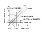
- FIG. 2 shows the relationship between the convergence and the adjustment for comfortable stereoscopic viewing.
- Convergence and accommodation are preferable for comfortable stereoscopic vision in humans, but it is known from studies of visual fatigue that there is some tolerance even if they do not coincide (T. Shibata, J. Kim, DM Hoffman, MS Banks, "The zone of comfort: Predicting visual discomfort with stereo displays," J. Vision, vol. 11, no. 8, p.1-29 (2011)).
- the amount of discrepancy between convergence and accommodation can be expressed using the distal end D far and the proximal end D near of the eye focus position with respect to the depth Dv perceived by the convergence.
- D far and D near use Dv
- D far 1.129 Dv + 0.442
- D near 1.035Dv-0.626 (1b)
- D far , D near , and Dv are given in units of a diopter (Diopter [D]) representing the reciprocal of the distance in meters.
- inconsistency between congestion and regulation is allowed.
- the focus of the eye is set to 0.5D (equal to 2 m)
- the range of depth Dv perceived by the corresponding vergence is 0.051 to 1.1D. (0.92 to 19 m). That is, when the virtual image display surfaces Va and Vb are located at a distance of 2 m from the left eye Ea and the right eye Eb, if a stereoscopic image is displayed within a range of 0.92 to 19 m, visual fatigue due to the contradiction of convergence adjustment may be felt. You can comfortably see stereoscopic images.
- the range in which the stereoscopic image can be comfortably viewed is sufficiently wide in the distance from the virtual image display surfaces Va and Vb, but is not sufficiently wide in the near area.
- a virtual image is formed at a distance of infinity from a point several meters (typically 2 m) ahead of the left eye Ea and the right eye Eb and a stereoscopic image is spread in front of the user ( Since the stereoscopic image is typically displayed interactively by displaying it in the area of about 60 cm from the left eye Ea and the right eye Eb), in the stereoscopic display of the HMD1, the comfortable stereoscopic viewing range is widened to the near side. Is desirable.
- Wide-focus lenses 5a and 5b for the left and right eyes having negative focal lengths are used in order to widen a comfortable stereoscopic view closer to the virtual image display surfaces Va and Vb.
- the focal length ranges of the left-eye and right-eye wide-focus lenses 5a and 5b are f 1 to f 2 , and the left-eye and right-eye wide-focus lenses 5a and 5b to the virtual image display surfaces Va and Vb.
- the distance is l 0 .
- the allowable convergence range obtained by D far and D near is 0.64 to, depending on the near spread of the virtual image forming range (that is, l 1 ( ⁇ l 0 )). It spreads as close as 19 m (0.051 to 1.6 D), which makes it possible to comfortably stereoscopically view in a work space extending in front of the user.
- the following is an example of the design of left-eye and right-eye wide-focus lenses 5a and 5b having a negative focal length and a wide range.
- FIG. 3 shows the shapes (A) of the left-eye and right-eye wide-focus lenses 5a and 5b and the distribution (B) of the focal length with respect to the distance from the center.
- the focal length is represented by the reciprocal of the refractive power.
- the wide-focus lens has a refractive power with a negative value and a minimum absolute value (zero in this embodiment) at the optical center, and has a negative value and a larger absolute value with increasing distance from the optical center. .
- axicon G. Mikula, Z. Jaroszewicz, A. Kolodziejczyk, K. Petelczyc, and M. Sypek, "Images with extended focal depth by means “Opt. Express, vol. 15, no. 15, p.9184-9193 (2007)), Axilens (axilens) (J. Sochacki, A. Kolodziejczyk, Z. Jaroszewicz, and S. Bara," Nonparaxial design of generalized axicons, "Appl. Opt., vol.31, p.5326-5330 (1992)), light sword optical element (N. Davidson, A. A. Friesem, and E.
- the refractive power (the reciprocal of the focal length f ⁇ 1 ) is Using the rate n, Is given.
- Z (r) Er 3 is given by using the coefficient E to obtain a distribution of refractive power, Is obtained.
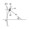
- FIG. 4 shows the surface shape of the wide-focus lens.
- Is minute change dr of the distance r corresponding to the minute length ds along the lens surface and the minute length dZ in the thickness direction.
- the focal length f of the spherical surface having the radius of curvature R is Is given.
- Expression (3) is derived by applying these relational expressions to Expression (6).
- the optical centers of the left-eye and right-eye wide-focus lenses 5a and 5b are left and right with respect to the optical centers (that is, optical axes) of the left-eye and right-eye virtual image forming optical systems 4a and 4b, respectively.
- the lenses are arranged so as to shift toward the center side of both lenses in the direction, that is, closer to the center line L.
- the shift amounts ⁇ of the optical centers of the left-eye and right-eye wide-focus lenses 5a and 5b with respect to the optical axes of the left-eye and right-eye virtual image forming optical systems 4a and 4b are determined.
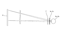
- FIG. 5A shows, as a comparative example, the relationship between the angle of the line of sight and the position in the wide-focus lenses 5a and 5b through which the line of sight passes in a stereoscopic display device with a small angle of view such as a stereoscopic movie or a stereoscopic television.
- the user wears stereoscopic glasses to which the wide-focus lenses 5a and 5b and the filter F are attached, and looks at the display surface D of the display to see a stereoscopic image.
- the filter F is an optical element such as a polarization filter, a liquid crystal shutter, a color filter, or a spectral filter for separating left-eye and right-eye images.
- the light emitted from the display surface D of the display enters the left eye Ea and the right eye Eb via the wide-focus lenses 5a and 5b.
- the display surface The angle of view of D is small, and the light ray group that is emitted from each point on the display surface D and is incident on the left eye Ea and the right eye Eb is a wide-focus lens regardless of the position on the display surface D where the light ray group is emitted.
- 5a and 5b pass through substantially the same position, particularly the optical center. Therefore, the range of the focal lengths of the wide-focus lenses 5a and 5b can be regarded as constant with respect to the viewing direction (that is, the line-of-sight angle) of viewing the display surface D of the display from both eyes Ea and Eb.
- FIG. 5B shows the relationship between the line-of-sight angle and the positions in the wide-focus lenses 5a and 5b through which the line of sight passes in the HMD 1 having a large angle of view.
- a wide angle of view is preferred in order to enhance the immersive feeling, and thus the angles of view of the virtual image display surfaces Va and Vb become large.
- the wide-focus lenses 5a and 5b should be attached to the left eye. It is also necessary to have some separation from Ea and the right eye Eb.
- the light ray group that is emitted from each point of the screen 3c (virtually virtual image display surfaces Va, Vb) of the display device 3 and is incident on the left eye Ea and the right eye Eb has a wide focus depending on the position of each point.
- the lenses 5a and 5b pass through different positions, particularly a range that spreads larger than the pupil. Therefore, the focal lengths and widths of the wide-focus lenses 5a and 5b are different with respect to the viewing direction (that is, the line-of-sight angle) of viewing the virtual image display surfaces Va and Vb from the left eye Ea and the right eye Eb.
- the effect of 5b on virtual image formation that is, how the allowable range of convergence and accommodation spreads changes depending on the viewing direction.
- the areas (II) outside the left-eye and right-eye wide-focus lenses 5a and 5b correspond to the stereoscopic viewing area As, and the allowable range of convergence and adjustment becomes effective. I can't spread it.
- the area (I) near the centers of the left-eye and right-eye wide-focus lenses 5a and 5b is located on the center line L side so as to face the area As. shift.
- the area Am since the virtual image of the two-dimensional display is viewed by only one of the left eye Ea and the right eye Eb, the contradiction of convergence adjustment does not occur.
- the optical centers 5a 0 and 5b 0 of the left-eye and right-eye wide-focus lenses 5a and 5b with respect to the optical axes of the left-eye and right-eye virtual image forming optical systems 4a and 4b (that is, , Optical axis) shift amount ⁇ is a distance P in the left-right direction between the left-eye and right-eye virtual image forming optical systems 4a and 4b, the left-eye and right-eye wide-focus lenses 5a and 5b, and the user's left-eye.
- the range Av in which the left-eye and right-eye wide-focus lenses 5a and 5b display virtual images that is, from the left-eye and right-eye wide-focus lenses 5a and 5b
- the shift amount ⁇ may be determined as Pd / 2Q with respect to the distance Q between the pupils of the user's left eye Ea and right eye Eb and the user's hand, or Pd / 2Q to Pd / 2 ( It may be determined to be within the range of l 0 + d). This enables comfortable stereoscopic viewing within a large work area in front of the user.
- the shift amount ⁇ may be zero when the stereoscopic image is displayed in a narrow range, or when the observation distance is long and the angle of view for that range is small.
- the actuators 6a and 6b are examples of displacement mechanisms, and drive the left-eye and right-eye wide-focus lenses 5a and 5b in the left-right direction with respect to the left-eye and right-eye virtual image forming optical systems 4a and 4b, respectively.
- Drive device An electric motor, for example, can be used as the actuators 6a and 6b.
- the actuators 6a and 6b are respectively held inside the left and right side surfaces of the frame 2 and actuated by operation buttons provided on the side surfaces of the frame 2 to operate the left-eye and right-eye wide-focus lenses 5a and 5b.
- the drive range may include any of the ranges described above. Accordingly, the display range of the stereoscopic image that can be viewed without suffering visual fatigue due to the contradiction of convergence adjustment can be displaced in the direction parallel to the center line L.
- a device for displacing the left-eye and right-eye wide-focus lenses 5a, 5b in the left-right direction by manually operating a dial, a ring, etc. instead of a drive device having a power source such as the actuators 6a, 6b. May be adopted.
- the left-eye and right-eye wide-focus lenses 5a and 5b may be displaced in the left-right direction and tilted. If the shift amount ⁇ does not have a range or the range is sufficiently narrow, the displacement mechanism is not provided and the left-eye and right-eye virtual image forming optical systems 4 a and 4 b may be fixed in the frame 2. .
- the display device 3 that displays the left-eye and right-eye images 3a and 3b on the screen 3c, and the left-eye and right-eye images on the screen 3c.
- the left-eye and right-eye wide-focus lenses 5a and 5b each having a negative focal length and a width are provided so as to be overlapped with each other in the direction.
- Virtual images of the left-eye and right-eye images 3a and 3b formed by the left-eye and right-eye virtual image-forming optical systems 4a and 4b are respectively left-eye and right-eye virtual image-forming optical systems 4a. , 4b with respect to the optical axis directions of the left-eye and right-eye wide-focus lenses 5a and 5b, the focal lengths of the respective wide-focus lenses 5a and 5b are displayed in a range having a width that widens in the vicinity, that is, As the display range of the virtual image expands to the near side, the allowable range of convergence and adjustment expands to the near side, so that it is displayed by the left-eye and right-eye images 3a and 3b in the near wide area. It is possible to view a stereoscopic image without suffering visual fatigue caused by the contradiction of convergence adjustment.
- the left-eye and right-eye wide-focus lenses 5a and 5b having a negative focal length and a wide width are provided in the existing HMD for the left-eye and the right-eye.
- the virtual image forming optical systems 4a and 4b so as to overlap each other in the optical axis direction, the display range of the virtual image is expanded closer to the virtual image display surfaces Va and Vb, thereby allowing convergence and adjustment.
- the stereoscopic image represented by the left-eye and right-eye images 3a and 3b can be viewed within the wide area in the vicinity without suffering visual fatigue due to the contradiction of convergence adjustment. It becomes possible.
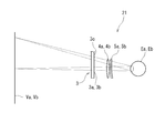
- FIG. 7 shows a schematic configuration of an AR HMD (simply referred to as an HMD unless there is confusion) 11 according to the second embodiment.
- the HMD 11 includes a frame 12, left eye and right eye display devices 13a and 13b, left eye and right eye half mirrors 17a and 17b, left eye and right eye virtual image forming optical systems 4a and 4b, and left eye. And right-eye wide-focus lenses 5a and 5b, and actuators 6a and 6b.
- the same components as those of the HMD 1 according to the first embodiment are designated by the same reference numerals and the description thereof will be omitted.
- the frame 12 is a housing that holds the left-eye and right-eye display devices 13a and 13b and other components.
- the frame 12 holds the left-eye and right-eye display devices 13a and 13b inside the left and right side surfaces, respectively, and has a back surface opened so that the inside can be viewed from the back side.
- Has a translucent front surface so as to face the front, and on the main line of sight La, Lb of the left eye Ea and the right eye Eb so that the display surfaces of the left and right eye display devices 13a, 13b can be seen.
- the left-eye and right-eye half mirrors 17a and 17b are held, respectively.
- the main line of sight La, Lb of the left eye Ea and the right eye Eb, which are bent through the left-eye and right-eye half mirrors 17a, 17b, respectively, is for the left eye and the right eye, respectively.
- the left-eye and right-eye virtual image forming optical systems 4a and 4b are held in the frame 12 so as to overlap or substantially overlap the optical axes 4a 0 and 4b 0 of the virtual image forming optical systems 4a and 4b. .
- the left-eye and right-eye display devices 13a and 13b are devices that respectively display left-eye and right-eye images 3a and 3b on their respective screens (also referred to as left-eye and right-eye screens).
- the display devices 13a and 13b for example, flat panel displays such as liquid crystal displays and organic EL displays can be used.
- the left-eye display device 13a is held inside the left side surface of the frame 12 with the screen facing right.
- the right-eye display device 13b is held inside the right side surface of the frame 12 with the screen facing left.
- the left-eye and right-eye half mirrors 17a and 17b reflect the left-eye and right-eye images 3a and 3b displayed on the screens of the left-eye and right-eye display devices 13a and 13b, respectively. It is an optical member for realizing a see-through function in which the light from the target object in front is transmitted to be overlapped with each other to be projected on the left eye Ea and the right eye Eb.
- the left-eye half mirror 17a is on the opposite side to the left-eye screen (left-eye display device 13a) of the left-eye virtual image forming optical system 4a and in front of the user's left-eye Ea (that is, on the main line of sight La). Will be placed.
- the right-eye half mirror 17b is on the opposite side of the right-eye virtual image forming optical system 4b from the right-eye screen (right-eye display device 13b) and in front of the user's right eye Eb (that is, on the main line of sight Lb). Will be placed.
- the left-eye and right-eye virtual image forming optical systems 4a and 4b are arranged on the left and right sides in the frame 12 toward the screens of the left-eye and right-eye display devices 13a and 13b, respectively, and are for the left-eye.
- images 3a and 3b for the right eye are formed as virtual images on the front virtual image display surfaces Va and Vb, respectively, and their enlarged erect images are projected to the left eye Ea and the right eye Eb.
- the virtual image on the virtual image display surface Va in the overlapping region of the virtual image display surfaces Va and Vb is viewed by the left eye Ea and at the same time.
- the virtual image on Vb with the right eye Eb it is possible to stereoscopically view the virtual image in the region As that faces the overlapping region from both eyes, overlapping the target actually existing in the region. That is, the stereoscopic image is projected on the target object in the area As.
- the left-eye and right-eye wide-focus lenses 5a and 5b are wide-focus lenses having a negative focal length and a wide width, and they are provided to the left-eye and right-eye virtual image forming optical systems 4a and 4b, respectively. Are arranged so as to overlap each other in the optical axis direction. As a result, the virtual images of the left-eye and right-eye images 3a and 3b formed by the left-eye and right-eye virtual image forming optical systems 4a and 4b become the left-eye and right-eye wide-focus lenses 5a, Since the focal length of 5b has a width, it is displayed within a range having a width that spreads in the front-rear direction far and / or near the virtual image display surfaces Va and Vb.
- the focal lengths of the left-eye and right-eye wide-focus lenses 5a and 5b are the same as those of the HMD 1 according to the first embodiment so that a stereoscopic image can be viewed without suffering visual fatigue caused by the contradiction of convergence adjustment. It can be defined similarly.
- the image forming range of the virtual image expands closer to the virtual image display surfaces Va and Vb, and the range in which the mismatch between the convergence and the adjustment is allowed expands closer to the user. It becomes possible to see.
- the optical centers 5a 0 and 5b 0 of the left-eye and right-eye wide-focus lenses 5a and 5b are the optical centers of the left-eye and right-eye virtual image forming optical systems 4a and 4b, respectively (that is, The optical axes 4a 0 , 4b 0 ) are arranged rearward, that is, shifted toward the center line L via the left-eye and right-eye half mirrors 17a, 17b.
- the shift amount ⁇ of 0 can be determined similarly to the HMD 1 according to the first embodiment. As a result, it becomes possible to widen the range where comfortable stereoscopic viewing is possible in the stereoscopic viewing area As.
- the actuators 6a and 6b are examples of displacement mechanisms, and the left-eye and right-eye wide-focus lenses 5a and 5b are arranged in the front-rear direction (that is, the left-eye and right-eye virtual image forming optical systems 4a and 4b). , A left-right and a right-eye half mirror 17a, 17b via the left and right direction) driving device.
- the actuators 6a and 6b are respectively held on the left and right of the front surface of the frame 12, and actuated by operation buttons provided on the side surface of the frame 12 to move the left-eye and right-eye wide-focus lenses 5a and 5b in the front-back direction. Drive to. Accordingly, the display range of the stereoscopic image that can be viewed without suffering visual fatigue due to the contradiction of convergence adjustment can be displaced in the direction parallel to the center line L.
- the left-eye and right-eye wide-focus lenses 5a and 5b may be displaced in the front-rear direction and tilted.
- the left-eye display device 13a, the left-eye virtual image forming optical system 4a, and the left-eye wide-focus lens 5a in the frame 12 are left-eye half on the main line of sight La. Although it is arranged on the left side of the mirror 17a, it may be arranged above or below the left-eye half mirror 17a instead.
- the right-eye display device 13b, the right-eye virtual image forming optical system 4b, and the right-eye wide-focus lens 5b in the frame 12 are arranged on the main line of sight Lb for the right-eye half. Although it is arranged on the right side of the mirror 17b, it may be arranged above or below the right-eye half mirror 17b instead.
- the left-eye and right-eye display devices 13a and 13b which display the left-eye and right-eye images 3a and 3b on the screen, respectively.
- the left-eye and right-eye virtual image forming optical systems 4a and 4b and the left-eye and right-eye virtual image forming optical systems 4a and 4b which are arranged for the eye and right-eye images 3a and 3b, respectively.
- the half mirror 17a for the left eye which is arranged on the opposite side to the front of the left eye Ea of the user, and the half mirror 17a for the left eye, which is arranged on the opposite side of the screen for the right eye of the virtual image forming optical system 4b for the right eye and in front of the right eye Eb of the user.
- the right-eye half mirror 17b is provided.
- Virtual images of the left-eye and right-eye images 3a and 3b formed by the left-eye and right-eye virtual image forming optical systems 4a and 4b are left-eye and right-eye wide-focus lenses 5a and 5b, respectively.
- each focal length has a width
- it is displayed within a range having a width that expands in the near direction, that is, the display range of the virtual image expands in the near direction, and the allowable range for congestion and adjustment is near Therefore, it is possible to view the stereoscopic images represented by the left-eye and right-eye images 3a and 3b in a wide area in the vicinity without suffering visual fatigue due to the contradiction of convergence adjustment.
- the wide-eye lenses 5a and 5b for the left eye and the right eye having a negative focal length and a wide width are provided in the existing HMD for the left eye and the right eye.
- the virtual image forming optical systems 4a and 4b so as to overlap each other in the optical axis direction, the display range of the virtual image is expanded closer to the virtual image display surfaces Va and Vb, thereby allowing convergence and adjustment.
- the stereoscopic image represented by the left-eye and right-eye images 3a and 3b can be viewed within the wide area in the vicinity without suffering visual fatigue due to the contradiction of convergence adjustment. It becomes possible.
- the left-eye and right-eye virtual image forming optical systems 4a and 4b and the left-eye and right-eye wide-focus lenses 5a that are independently configured, respectively. , 5b, but instead, an imaging system having at least one free-form lens designed to have both functions of a virtual image forming optical system and a wide-focus lens is provided for the left eye and the right eye. You may be prepared for this.
- the left-eye and right-eye half mirrors 17a and 17b are used to have the see-through function, but instead of this, the planar waveguide is used for downsizing the device. Also, holographic optical elements may be used in combination.
- the left-eye and right-eye images 3a and 3b displayed by the display device 3 and the left-eye and right-eye display devices 13a and 13b may be in color. Monochrome is also acceptable. In the case of color, an optical system for correcting chromatic aberration may be further provided.
- the basic configuration of the HMD 21 is the same as the HMD 1 according to the first embodiment, and the HMD 21 uses the wide-focus lens 25 shown below as the left-eye and right-eye wide-focus lenses 5a and 5b. Is different.
- the wide-focus lens 25 is a lens in which the refractive power (power) at the optical center is 0 diopter and the average power gradually changes from the optical center toward the lens peripheral portion toward the negative side. Since the focal length is represented by the reciprocal of the refractive power, the wide-focus lens 25 has a negative focal length and a wide width.
- the front, back, left and right, and the top and bottom of the user wearing the HMD 21 using the wide-focus lens 25 are referred to as the front, rear, left and right, and the top and bottom of the lens, respectively.
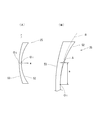
- FIG. 8A shows an overall schematic view of the wide-focus lens 25.
- the rear surface 52 is a concave surface defined by the following expression (7)
- the front surface 53 is a convex surface defined by the following expression (8).
- the axis in the front-back direction that passes through the optical center O of the wide-focus lens 25 (the base point O 1 on the rear surface 52 and the base point O 2 on the front surface 53) is the z-axis
- the direction toward the rear of the wide-focus lens 25 is the z-axis.
- the z axis coincides with the optical axis of the wide focus lens 25.
- R in the equations (7) and (8) is the distance from the z axis. That is, when considering an orthogonal coordinate system with the base point O 1 on the rear surface 52 and the base point O 2 on the front surface 53 as centers, the horizontal and vertical axes orthogonal to the z-axis are the x-axis and the y-axis, respectively. (X 2 + y 2 ) 1/2 . R 1 and R 2 are radii of curvature at the vertices of the surface, and K (conic coefficient) is 1.
- ⁇ 1 is represented by Ar 4 + Br 6 + Cr 8 + Dr 10 (where r is the distance from the z axis and A, B, C, and D are constants). It is the first aspherical component.
- ⁇ 2 is a second aspherical component represented by Er 3 (where r is the distance from the z axis and E is a positive constant). Therefore, in the wide-focus lens 25 of this example, the front surface 53 is spherical and the rear surface 52 is aspherical. Note that R 1 and R 2 are determined by the prescription frequency (0D in this example).
- the wide-focus lens 25 of this example has a refracting surface of the lens rear surface 52 determined based on the prescription power (a spherical surface having a radius of curvature R 1 in this example.
- a spherical surface having a radius of curvature R 1 in this example also referred to as an original spherical surface, which is indicated by a symbol S). .
- aspherical components ⁇ 1 and ⁇ 2 are added.
- the second aspherical component ⁇ 2 represented by Er 3 is substantially linear from the optical center toward the lens peripheral edge along the radial direction of the lens with the average power ⁇ toward the minus side. Has the effect of changing to. Therefore, according to the wide-focus lens 25, the focusable range is widened and the focal length can be widened.
- the value of the constant E can be appropriately set so as to obtain a target allowable range of congestion and adjustment.
- the constant E is 1.66 ⁇ 10 ⁇ 5
- the average dioptric power change in stereoscopic vision is about 0.5 D when the pupil diameter is 5 mm, and the congestion and adjustment are adjusted to the extent illustrated in paragraphs 0023 to 0025. It is possible to widen the allowable range with.
- ⁇ is the height in the z-axis direction at the radius a with the original spherical surface S as a reference (that is, the increase in thickness from the original spherical surface S)
- E 7.68 ⁇ 10 ⁇ 6
- a is 25 mm and ⁇ indicating the increase in thickness is 120 ⁇ m.
- E ⁇ / 1000 / a 3 holds (however, the unit of a: mm, the unit of ⁇ : ⁇ m).
- the refractive surface of the front surface 53 and the refractive surface of the rear surface 52 of the wide-focus lens 25 are determined based on the prescription power. This determination method is well known and will not be described in detail here.
- an aspherical component is added to the refracting surface (original spherical surface S) of the rear surface 52 of the lens determined based on the prescription power.
- An aspherical component is added to the refracting surface of the rear surface 52 by the second aspherical component adding step of adding the second aspherical component ⁇ 2 .
- the first aspherical surface component adding step the first aspherical surface component ⁇ represented by Ar 4 + Br 6 + Cr 8 + Dr 10 (where r is the distance from the z axis and A, B, C and D are constants). 1 is obtained and added to the refracting surface of the rear surface 52.
- the average dioptric power can be made substantially constant along the radial direction of the lens, as indicated by the broken line ⁇ in FIG.
- the first aspherical component ⁇ 1 is obtained by performing a ray tracing simulation on the refracting surface shape of the rear surface 52 expressed by the following aspherical expression (9), and calculating the power (specifically, the refractive power in the meridional direction and the sagittal direction).
- the optimum aspherical surface coefficients A, B, C, D for suppressing the change of the average power with the refractive power in the direction) are obtained, and the first aspherical surface component ⁇ 1 is calculated from the values of these aspherical surface coefficients. Obtainable.
- z r 2 / (R 1 + (R 1 2 -Kr 2 ) 1/2 ) + Ar 4 + Br 6 + Cr 8 + Dr 10 (9)
- z is the sag value on the rear surface 52
- r is the distance from the z axis
- R 1 is the radius of curvature of the vertex
- A, B, C and D are constants (aspherical coefficients).
- a second aspherical surface component ⁇ 2 represented by Er 3 (where r is a distance from the z axis and E is a constant) is added to the refracting surface of the rear surface 52.
- E is a constant
- the absolute value of the constant E is increased, the range in which stereoscopic viewing can be comfortably performed (allowable range between convergence and adjustment) can be expanded.
- the absolute value of the constant E is excessively increased, the resolution of the obtained image will decrease. Therefore, it is preferable to set the constant E so that the absolute value of the constant E falls within the range of 6.40 ⁇ 10 ⁇ 7 to 6.40 ⁇ 10 ⁇ 5 .
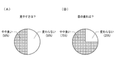
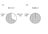
- FIG. 11 and 12 show the evaluation results of the wide-focus lens of Example 3.
- FIG. 11 is a result (number of answers: 4) obtained 30 minutes after the start of viewing the movie.
- FIG. 12 is a result (number of answers: 3) obtained 120 minutes after the start of viewing.
- the results of “somewhat good” were more than half of the results of the wide-focus lens of Example 2 in terms of “ease of viewing” and “eye strain”. Especially when the viewing time was long, the ratio of "somewhat good” was high. Further, the wide-focus lenses of the other Examples 1, 2 and 4 have almost the same results. By using a wide-focus lens that has the effect of widening the virtual image display range to the near side due to the wide focal length, it is thought that this is due to the effect of expanding the display range of the stereoscopic image that can be comfortably stereoscopically viewed to the near side. To be
- the HMD 21 is for the left eye and the right eye, which are respectively overlapped with the left-eye and right-eye virtual image forming optical systems 4a and 4b in the respective optical axis directions.
- the wide-focus lenses 5a and 5b are obtained by adding a second aspherical component represented by Er 3 together with a first aspherical component represented by Ar 4 + Br 6 + Cr 8 + Dr 10 .
- the power of the wide-focus lenses 5a and 5b changes in the radial direction due to the second aspherical component represented by Er 3 . That is, the focal lengths of the wide-focus lenses 5a and 5b have a width and the range in which a virtual image is formed spreads in the optical axis direction, and accordingly, comfort is achieved without suffering visual fatigue due to contradiction of convergence adjustment. It is possible to widen the allowable range of convergence and adjustment that can see a stereoscopic image.
- FIG. 10 is a diagram showing a relationship between the user's line of sight and the wide-focus lenses 5a and 5b in the HMD 21 having a large angle of view.
- a wide angle of view is preferred to enhance the immersive feeling, and the angles of view of the virtual image display surfaces Va and Vb become large. Therefore, the group of light rays emitted from the screen 3c of the display device 3 and incident on the left eye Ea and the right eye Eb are close to the peripheral portions as well as the central portions of the wide-focus lenses 5a and 5b, as shown in FIG. It may pass through the area.
- the light ray group incident on the left eye Ea or the right eye Eb is a lens of the wide-focus lenses 5a and 5b. Even when passing through the region close to the peripheral portion, it is possible to ensure the effect of the wide-focus lenses 5a and 5b on virtual image formation, that is, the effect of widening the allowable range of convergence and adjustment.
- the HMD 21 of the above embodiment is a VR HMD, it is also possible to use the wide-focus lens 25 for an AR HMD.
- the above embodiment is an example in which the first aspherical component ⁇ 1 is added to the rear surface 52 of the wide-focus lens, but the first aspherical component ⁇ 1 is added to the front surface 53 of the wide-focus lens. Alternatively, it may be added to both the front surface 53 and the rear surface 52.
- the first aspherical component ⁇ 1 represented by Ar 4 + Br 6 (in this case, the values of constants C and D are zero) is added to the front surface 53, and further the rear surface 52 is represented by Cr 8 + Dr 10. It is also possible to add the first aspherical component ⁇ 1 (in this case, the values of the constants A and B are zero). Whatever surface is added, it is sufficient that fluctuation of the average power from the optical center to the lens peripheral portion can be suppressed.
- the above embodiment is an example in which the second aspherical component ⁇ 2 is added to the rear surface 52 of the wide-focus lens, but the second aspherical component ⁇ 2 is added to the front surface 53 of the wide-focus lens. It is also possible.
- a wide-focus lens in which a power component for correcting at least any of myopia, hyperopia, and astigmatism is further set. It is also possible to use.
- HMD Head mounted display
- 2 ... Frame
- 3 ... Display device 3a ... Left eye image, 3b ... Right eye image, 3c ... Screen
- 4a Left eye virtual image formation optics (virtual image forming optical system), 4b ... right-eye virtual image forming optical system (a virtual image forming optical system), 4a 0, 4b 0 ... optical axis, 5a ... left eye wide lens (wide lens) 5b ... wide-focus lens for right eye (wide-focus lens), 5a 0 , 5b 0 ...
- Optical center 6a, 6b ... Actuator, 11 ... Head mounted display (HMD, HMD for AR), 12 ... Frame, 13a ...
Landscapes
- Physics & Mathematics (AREA)
- General Physics & Mathematics (AREA)
- Optics & Photonics (AREA)
- Health & Medical Sciences (AREA)
- Ophthalmology & Optometry (AREA)
- General Health & Medical Sciences (AREA)
- Acoustics & Sound (AREA)
- Otolaryngology (AREA)
- Lenses (AREA)
Priority Applications (4)
| Application Number | Priority Date | Filing Date | Title |
|---|---|---|---|
| US16/617,689 US11740459B2 (en) | 2018-10-15 | 2019-07-22 | Head-mounted display and method for designing wide-focus lens to be used for the head-mounted display |
| CN201980002658.7A CN111328380B (zh) | 2018-10-15 | 2019-07-22 | 头戴式显示器以及头戴式显示器中使用的广焦点透镜的设计方法 |
| EP19805873.7A EP3663835B1 (de) | 2018-10-15 | 2019-07-22 | Am kopf montierte anzeige und verfahren zum entwurf einer weitfokuslinse für die am kopf montierte anzeige |
| JP2020502732A JP7533858B2 (ja) | 2018-10-15 | 2019-07-22 | ヘッドマウントディスプレイおよびこれに用いられる広焦点レンズの設計方法 |
Applications Claiming Priority (4)
| Application Number | Priority Date | Filing Date | Title |
|---|---|---|---|
| JP2018-194640 | 2018-10-15 | ||
| JP2018194640 | 2018-10-15 | ||
| JP2019001404 | 2019-01-08 | ||
| JP2019-001404 | 2019-01-08 |
Publications (1)
| Publication Number | Publication Date |
|---|---|
| WO2020079906A1 true WO2020079906A1 (ja) | 2020-04-23 |
Family
ID=70283863
Family Applications (1)
| Application Number | Title | Priority Date | Filing Date |
|---|---|---|---|
| PCT/JP2019/028635 Ceased WO2020079906A1 (ja) | 2018-10-15 | 2019-07-22 | ヘッドマウントディスプレイおよびこれに用いられる広焦点レンズの設計方法 |
Country Status (5)
| Country | Link |
|---|---|
| US (1) | US11740459B2 (de) |
| EP (1) | EP3663835B1 (de) |
| JP (1) | JP7533858B2 (de) |
| CN (1) | CN111328380B (de) |
| WO (1) | WO2020079906A1 (de) |
Cited By (2)
| Publication number | Priority date | Publication date | Assignee | Title |
|---|---|---|---|---|
| CN112068326A (zh) * | 2020-09-17 | 2020-12-11 | 京东方科技集团股份有限公司 | 3d显示装置 |
| JP2024174671A (ja) * | 2023-06-05 | 2024-12-17 | 国立大学法人東京農工大学 | 立体メガネ |
Families Citing this family (7)
| Publication number | Priority date | Publication date | Assignee | Title |
|---|---|---|---|---|
| CN112384840A (zh) * | 2018-07-11 | 2021-02-19 | 华为技术有限公司 | 用于使摄像头设备的光轴位移的可拆卸光学结构 |
| CN114185169B (zh) * | 2020-08-25 | 2024-03-05 | 成都理想境界科技有限公司 | 一种散射屏参数优化方法、散射屏及可读存储介质 |
| CN112255789B (zh) * | 2020-10-21 | 2022-04-22 | 京东方科技集团股份有限公司 | 虚拟现实显示光学系统及虚拟现实设备 |
| CN113671607B (zh) * | 2020-12-14 | 2022-10-25 | 明月镜片股份有限公司 | 一种双面非球面镜片及其设计方法 |
| CN115128802B (zh) * | 2021-03-24 | 2025-09-23 | 群创光电股份有限公司 | 影像的显示方法 |
| CN115590733A (zh) * | 2021-07-08 | 2023-01-13 | 华为技术有限公司(Cn) | 一种视力训练方法及装置 |
| CN117795396A (zh) * | 2021-08-20 | 2024-03-29 | 索尼集团公司 | 显示设备和显示方法 |
Citations (8)
| Publication number | Priority date | Publication date | Assignee | Title |
|---|---|---|---|---|
| JPH09297282A (ja) | 1996-05-01 | 1997-11-18 | Nippon Telegr & Teleph Corp <Ntt> | ヘッドマウントディスプレイ装置 |
| JP2005227682A (ja) * | 2004-02-16 | 2005-08-25 | Victor Co Of Japan Ltd | 立体画像表示装置 |
| JP2012078670A (ja) * | 2010-10-04 | 2012-04-19 | Hoya Corp | 立体映像観察用眼鏡 |
| WO2015137165A1 (ja) | 2014-03-14 | 2015-09-17 | 株式会社ソニー・コンピュータエンタテインメント | ヘッドマウントディスプレイ |
| JP2016024273A (ja) * | 2014-07-17 | 2016-02-08 | 株式会社ソニー・コンピュータエンタテインメント | 立体画像提示装置、立体画像提示方法、およびヘッドマウントディスプレイ |
| US20160327793A1 (en) * | 2015-05-07 | 2016-11-10 | Shinyoptics Corp. | Autofocus head mounted display device |
| JP2016206338A (ja) | 2015-04-20 | 2016-12-08 | 伊藤光学工業株式会社 | 視力矯正用レンズの設計方法及び視力矯正用レンズ |
| JP2018084788A (ja) * | 2016-11-25 | 2018-05-31 | 伊藤光学工業株式会社 | 累進屈折力レンズの設計方法及び累進屈折力レンズ |
Family Cites Families (13)
| Publication number | Priority date | Publication date | Assignee | Title |
|---|---|---|---|---|
| US4577942A (en) * | 1983-02-22 | 1986-03-25 | Optical Systems International, Inc. | Laminated high correction eyeglass lens |
| JPH10282448A (ja) | 1997-04-04 | 1998-10-23 | Minolta Co Ltd | ディスプレイ |
| JP2002031776A (ja) | 2000-07-14 | 2002-01-31 | Canon Inc | 表示装置 |
| JP2003241081A (ja) * | 2002-02-20 | 2003-08-27 | Fuji Photo Optical Co Ltd | 全長の短い単焦点レンズ |
| US20130261744A1 (en) * | 2010-06-01 | 2013-10-03 | Elenza, Inc. | Implantable ophthalmic device with an aspheric lens |
| US9734622B2 (en) * | 2010-06-01 | 2017-08-15 | Vladimir Vaganov | 3D digital painting |
| US8953242B2 (en) * | 2011-03-31 | 2015-02-10 | Honeywell International Inc. | Varible focus stereoscopic display system and method |
| WO2015195549A1 (en) * | 2014-06-16 | 2015-12-23 | Vladimir Vaganov | 3d digital painting |
| TW201617690A (zh) * | 2014-08-13 | 2016-05-16 | 阿爾發普瑞米特斯股份有限公司 | 用於智慧型眼用佩戴品之處方鏡片 |
| US9681804B2 (en) * | 2015-01-12 | 2017-06-20 | X Development Llc | Hybrid lens system for head wearable display |
| CN106353892B (zh) * | 2015-07-24 | 2020-02-07 | 爱博诺德(北京)医疗科技股份有限公司 | 一种眼内镜 |
| US10551636B2 (en) * | 2015-07-24 | 2020-02-04 | Eyebright Medical Technology (Beijing) Co., Ltd. | Vision correction lens and method for preparation of the same |
| CN109725418B (zh) * | 2017-10-30 | 2020-10-16 | 华为技术有限公司 | 显示设备、用于调整显示设备的图像呈现的方法及装置 |
-
2019
- 2019-07-22 CN CN201980002658.7A patent/CN111328380B/zh active Active
- 2019-07-22 EP EP19805873.7A patent/EP3663835B1/de active Active
- 2019-07-22 US US16/617,689 patent/US11740459B2/en active Active
- 2019-07-22 WO PCT/JP2019/028635 patent/WO2020079906A1/ja not_active Ceased
- 2019-07-22 JP JP2020502732A patent/JP7533858B2/ja active Active
Patent Citations (8)
| Publication number | Priority date | Publication date | Assignee | Title |
|---|---|---|---|---|
| JPH09297282A (ja) | 1996-05-01 | 1997-11-18 | Nippon Telegr & Teleph Corp <Ntt> | ヘッドマウントディスプレイ装置 |
| JP2005227682A (ja) * | 2004-02-16 | 2005-08-25 | Victor Co Of Japan Ltd | 立体画像表示装置 |
| JP2012078670A (ja) * | 2010-10-04 | 2012-04-19 | Hoya Corp | 立体映像観察用眼鏡 |
| WO2015137165A1 (ja) | 2014-03-14 | 2015-09-17 | 株式会社ソニー・コンピュータエンタテインメント | ヘッドマウントディスプレイ |
| JP2016024273A (ja) * | 2014-07-17 | 2016-02-08 | 株式会社ソニー・コンピュータエンタテインメント | 立体画像提示装置、立体画像提示方法、およびヘッドマウントディスプレイ |
| JP2016206338A (ja) | 2015-04-20 | 2016-12-08 | 伊藤光学工業株式会社 | 視力矯正用レンズの設計方法及び視力矯正用レンズ |
| US20160327793A1 (en) * | 2015-05-07 | 2016-11-10 | Shinyoptics Corp. | Autofocus head mounted display device |
| JP2018084788A (ja) * | 2016-11-25 | 2018-05-31 | 伊藤光学工業株式会社 | 累進屈折力レンズの設計方法及び累進屈折力レンズ |
Non-Patent Citations (6)
| Title |
|---|
| G. MIKULAZ. JAROSZEWICZA. KOLODZIEJCZYKK. PETELCZYCM. SYPEK: "Images with extended focal depth by means of lenses with radial and angular modulation", OPT. EXPRESS, vol. 15, no. 15, 2007, pages 9184 - 9193 |
| J. SOCHACKIA. KOLODZIEJCZYKZ. JAROSZEWICZS. BARA: "Nonparaxial design of generalized axicons", APPL. OPT., vol. 31, 1992, pages 5326 - 5330, XP000294493, DOI: 10.1364/AO.31.005326 |
| N. DAVIDSONA. A. FRIESEME. HASMAN: "Holographic axilens: high resolution and long focal depth", OPT. LETT., vol. 16, 1991, pages 523 - 525, XP000179792 |
| N. PADMANABANR. KONRADT. STRAMERE.A. COOPERG. WETZSTEIN: "Optimizing virtual reality for all users through gaze-contingent and adaptive focus displays", PNAS, vol. 114, 2017, pages 2183 - 2188, XP055402339, DOI: 10.1073/pnas.1617251114 |
| T. SHIBATAJ. KIMD. M. HOFFMANM. S. BANKS: "The zone of comfort: Predicting visual discomfort with stereo displays", J. VISION, vol. 11, no. 8, 2011, pages 1 - 29, XP055171846, DOI: 10.1167/11.8.11 |
| X. HUH. HUA: "High-resolution optical see-through multi-focal-plane head-mounted display using freeform optics", OPT. EXPRESS, vol. 22, 2014, pages 13896 - 13903 |
Cited By (4)
| Publication number | Priority date | Publication date | Assignee | Title |
|---|---|---|---|---|
| CN112068326A (zh) * | 2020-09-17 | 2020-12-11 | 京东方科技集团股份有限公司 | 3d显示装置 |
| CN112068326B (zh) * | 2020-09-17 | 2022-08-09 | 京东方科技集团股份有限公司 | 3d显示装置 |
| JP2024174671A (ja) * | 2023-06-05 | 2024-12-17 | 国立大学法人東京農工大学 | 立体メガネ |
| JP7842409B2 (ja) | 2023-06-05 | 2026-04-08 | 国立大学法人東京農工大学 | 立体メガネ |
Also Published As
| Publication number | Publication date |
|---|---|
| JPWO2020079906A1 (ja) | 2021-09-02 |
| US20210286177A1 (en) | 2021-09-16 |
| JP7533858B2 (ja) | 2024-08-14 |
| CN111328380A (zh) | 2020-06-23 |
| EP3663835A4 (de) | 2021-06-23 |
| EP3663835A1 (de) | 2020-06-10 |
| EP3663835C0 (de) | 2025-07-09 |
| EP3663835B1 (de) | 2025-07-09 |
| US11740459B2 (en) | 2023-08-29 |
| CN111328380B (zh) | 2023-04-04 |
Similar Documents
| Publication | Publication Date | Title |
|---|---|---|
| JP7533858B2 (ja) | ヘッドマウントディスプレイおよびこれに用いられる広焦点レンズの設計方法 | |
| JP4155343B2 (ja) | 二つの光景からの光を観察者の眼へ代替的に、あるいは同時に導くための光学系 | |
| CN107407812B (zh) | 图像显示装置 | |
| KR101916079B1 (ko) | 하나 또는 그 이상의 프레넬 렌즈를 수반하는 헤드 장착 디스플레이 장치 | |
| JP6859362B2 (ja) | 頭部装着型仮想現実表示装置 | |
| JP5290092B2 (ja) | 眼鏡型画像表示装置 | |
| CN107209381B (zh) | 用于可头戴显示器的混合透镜系统 | |
| US7992996B2 (en) | Spectacles-type image display device | |
| CN111373307B (zh) | 立体眼镜、该立体眼镜中使用的眼镜镜片的设计方法以及立体图像的观察方法 | |
| US20070236800A1 (en) | Imaging systems for eyeglass-based display devices | |
| CN113341567A (zh) | 一种双焦面光波导近眼显示光学系统 | |
| JP2020024363A (ja) | 表示装置 | |
| JP7177356B2 (ja) | パーソナルディスプレイ用の接眼レンズ及びこのような接眼レンズを含むパーソナルディスプレイ | |
| CN115004084B (zh) | 头戴式显示器以及在该头戴式显示器中使用的虚像成像透镜 | |
| WO2020026749A1 (ja) | 表示装置 | |
| JP2019179083A (ja) | 画像表示装置 | |
| JP7842409B2 (ja) | 立体メガネ | |
| JP3833207B2 (ja) | 表示装置 | |
| JP2025154747A (ja) | 虚像表示装置及び虚像表示方法 | |
| JP2025512047A (ja) | 眼科機器、及び、レンズ要素 | |
| JP2004226958A (ja) | 立体観察装置 |
Legal Events
| Date | Code | Title | Description |
|---|---|---|---|
| ENP | Entry into the national phase |
Ref document number: 2019805873 Country of ref document: EP Effective date: 20191128 |
|
| ENP | Entry into the national phase |
Ref document number: 2020502732 Country of ref document: JP Kind code of ref document: A |
|
| NENP | Non-entry into the national phase |
Ref country code: DE |
|
| WWG | Wipo information: grant in national office |
Ref document number: 2019805873 Country of ref document: EP |