WO2020080221A1 - Matériau de couvercle pour emballages, et emballage - Google Patents
Matériau de couvercle pour emballages, et emballage Download PDFInfo
- Publication number
- WO2020080221A1 WO2020080221A1 PCT/JP2019/039826 JP2019039826W WO2020080221A1 WO 2020080221 A1 WO2020080221 A1 WO 2020080221A1 JP 2019039826 W JP2019039826 W JP 2019039826W WO 2020080221 A1 WO2020080221 A1 WO 2020080221A1
- Authority
- WO
- WIPO (PCT)
- Prior art keywords
- layer
- package
- width
- glass member
- less
- Prior art date
- Legal status (The legal status is an assumption and is not a legal conclusion. Google has not performed a legal analysis and makes no representation as to the accuracy of the status listed.)
- Ceased
Links
Images



Classifications
-
- H—ELECTRICITY
- H10—SEMICONDUCTOR DEVICES; ELECTRIC SOLID-STATE DEVICES NOT OTHERWISE PROVIDED FOR
- H10W—GENERIC PACKAGES, INTERCONNECTIONS, CONNECTORS OR OTHER CONSTRUCTIONAL DETAILS OF DEVICES COVERED BY CLASS H10
- H10W42/00—Arrangements for protection of devices
- H10W42/121—Arrangements for protection of devices protecting against mechanical damage
-
- B—PERFORMING OPERATIONS; TRANSPORTING
- B23—MACHINE TOOLS; METAL-WORKING NOT OTHERWISE PROVIDED FOR
- B23K—SOLDERING OR UNSOLDERING; WELDING; CLADDING OR PLATING BY SOLDERING OR WELDING; CUTTING BY APPLYING HEAT LOCALLY, e.g. FLAME CUTTING; WORKING BY LASER BEAM
- B23K1/00—Soldering, e.g. brazing, or unsoldering
- B23K1/0008—Soldering, e.g. brazing, or unsoldering specially adapted for particular articles or work
- B23K1/0016—Soldering of electronic components
-
- B—PERFORMING OPERATIONS; TRANSPORTING
- B23—MACHINE TOOLS; METAL-WORKING NOT OTHERWISE PROVIDED FOR
- B23K—SOLDERING OR UNSOLDERING; WELDING; CLADDING OR PLATING BY SOLDERING OR WELDING; CUTTING BY APPLYING HEAT LOCALLY, e.g. FLAME CUTTING; WORKING BY LASER BEAM
- B23K35/00—Rods, electrodes, materials, or media, for use in soldering, welding, or cutting
- B23K35/22—Rods, electrodes, materials, or media, for use in soldering, welding, or cutting characterised by the composition or nature of the material
- B23K35/24—Selection of soldering or welding materials proper
- B23K35/30—Selection of soldering or welding materials proper with the principal constituent melting at less than 1550°C
- B23K35/3013—Au as the principal constituent
-
- C—CHEMISTRY; METALLURGY
- C22—METALLURGY; FERROUS OR NON-FERROUS ALLOYS; TREATMENT OF ALLOYS OR NON-FERROUS METALS
- C22C—ALLOYS
- C22C5/00—Alloys based on noble metals
- C22C5/02—Alloys based on gold
-
- H—ELECTRICITY
- H01—ELECTRIC ELEMENTS
- H01S—DEVICES USING THE PROCESS OF LIGHT AMPLIFICATION BY STIMULATED EMISSION OF RADIATION [LASER] TO AMPLIFY OR GENERATE LIGHT; DEVICES USING STIMULATED EMISSION OF ELECTROMAGNETIC RADIATION IN WAVE RANGES OTHER THAN OPTICAL
- H01S5/00—Semiconductor lasers
- H01S5/02—Structural details or components not essential to laser action
- H01S5/022—Mountings; Housings
- H01S5/02218—Material of the housings; Filling of the housings
-
- H—ELECTRICITY
- H01—ELECTRIC ELEMENTS
- H01S—DEVICES USING THE PROCESS OF LIGHT AMPLIFICATION BY STIMULATED EMISSION OF RADIATION [LASER] TO AMPLIFY OR GENERATE LIGHT; DEVICES USING STIMULATED EMISSION OF ELECTROMAGNETIC RADIATION IN WAVE RANGES OTHER THAN OPTICAL
- H01S5/00—Semiconductor lasers
- H01S5/02—Structural details or components not essential to laser action
- H01S5/022—Mountings; Housings
- H01S5/0225—Out-coupling of light
- H01S5/02257—Out-coupling of light using windows, e.g. specially adapted for back-reflecting light to a detector inside the housing
-
- H—ELECTRICITY
- H10—SEMICONDUCTOR DEVICES; ELECTRIC SOLID-STATE DEVICES NOT OTHERWISE PROVIDED FOR
- H10H—INORGANIC LIGHT-EMITTING SEMICONDUCTOR DEVICES HAVING POTENTIAL BARRIERS
- H10H20/00—Individual inorganic light-emitting semiconductor devices having potential barriers, e.g. light-emitting diodes [LED]
- H10H20/80—Constructional details
- H10H20/85—Packages
-
- H—ELECTRICITY
- H10—SEMICONDUCTOR DEVICES; ELECTRIC SOLID-STATE DEVICES NOT OTHERWISE PROVIDED FOR
- H10H—INORGANIC LIGHT-EMITTING SEMICONDUCTOR DEVICES HAVING POTENTIAL BARRIERS
- H10H20/00—Individual inorganic light-emitting semiconductor devices having potential barriers, e.g. light-emitting diodes [LED]
- H10H20/80—Constructional details
- H10H20/85—Packages
- H10H20/8506—Containers
-
- H—ELECTRICITY
- H10—SEMICONDUCTOR DEVICES; ELECTRIC SOLID-STATE DEVICES NOT OTHERWISE PROVIDED FOR
- H10W—GENERIC PACKAGES, INTERCONNECTIONS, CONNECTORS OR OTHER CONSTRUCTIONAL DETAILS OF DEVICES COVERED BY CLASS H10
- H10W76/00—Containers; Fillings or auxiliary members therefor; Seals
- H10W76/10—Containers or parts thereof
-
- H—ELECTRICITY
- H10—SEMICONDUCTOR DEVICES; ELECTRIC SOLID-STATE DEVICES NOT OTHERWISE PROVIDED FOR
- H10W—GENERIC PACKAGES, INTERCONNECTIONS, CONNECTORS OR OTHER CONSTRUCTIONAL DETAILS OF DEVICES COVERED BY CLASS H10
- H10W76/00—Containers; Fillings or auxiliary members therefor; Seals
- H10W76/10—Containers or parts thereof
- H10W76/12—Containers or parts thereof characterised by their shape
-
- H—ELECTRICITY
- H10—SEMICONDUCTOR DEVICES; ELECTRIC SOLID-STATE DEVICES NOT OTHERWISE PROVIDED FOR
- H10W—GENERIC PACKAGES, INTERCONNECTIONS, CONNECTORS OR OTHER CONSTRUCTIONAL DETAILS OF DEVICES COVERED BY CLASS H10
- H10W76/00—Containers; Fillings or auxiliary members therefor; Seals
- H10W76/10—Containers or parts thereof
- H10W76/17—Containers or parts thereof characterised by their materials
- H10W76/18—Insulating materials, e.g. resins, glasses or ceramics
-
- H—ELECTRICITY
- H10—SEMICONDUCTOR DEVICES; ELECTRIC SOLID-STATE DEVICES NOT OTHERWISE PROVIDED FOR
- H10W—GENERIC PACKAGES, INTERCONNECTIONS, CONNECTORS OR OTHER CONSTRUCTIONAL DETAILS OF DEVICES COVERED BY CLASS H10
- H10W76/00—Containers; Fillings or auxiliary members therefor; Seals
- H10W76/60—Seals
-
- B—PERFORMING OPERATIONS; TRANSPORTING
- B23—MACHINE TOOLS; METAL-WORKING NOT OTHERWISE PROVIDED FOR
- B23K—SOLDERING OR UNSOLDERING; WELDING; CLADDING OR PLATING BY SOLDERING OR WELDING; CUTTING BY APPLYING HEAT LOCALLY, e.g. FLAME CUTTING; WORKING BY LASER BEAM
- B23K2101/00—Articles made by soldering, welding or cutting
- B23K2101/36—Electric or electronic devices
- B23K2101/40—Semiconductor devices
-
- H—ELECTRICITY
- H01—ELECTRIC ELEMENTS
- H01S—DEVICES USING THE PROCESS OF LIGHT AMPLIFICATION BY STIMULATED EMISSION OF RADIATION [LASER] TO AMPLIFY OR GENERATE LIGHT; DEVICES USING STIMULATED EMISSION OF ELECTROMAGNETIC RADIATION IN WAVE RANGES OTHER THAN OPTICAL
- H01S5/00—Semiconductor lasers
- H01S5/02—Structural details or components not essential to laser action
- H01S5/022—Mountings; Housings
- H01S5/02208—Mountings; Housings characterised by the shape of the housings
Definitions
- the present invention relates to a package lid member and a package that are joined to a package substrate.
- This application claims priority based on Japanese Patent Application No. 2018-194535 filed in Japan on October 15, 2018 and Japanese Patent Application No. 2019-184287 filed in Japan on October 7, 2019, and the contents thereof Is used here.
- the semiconductor device described in Patent Document 1 includes a package substrate having a recess whose upper portion is open, an optical semiconductor element housed in the recess, and a window member (package lid member arranged to cover the opening of the recess. ) And a sealing structure for sealing between the package substrate and the window member.
- This sealing structure includes a first metal layer provided in a frame shape on the upper surface of the package substrate, a second metal layer provided in a frame shape on the inner surface of the window member, and between the first metal layer and the second metal layer.
- a first metal layer and a second metal layer, and the whole of the other of the first metal layer and the second metal layer is located in a region where one of the first metal layer and the second metal layer is provided. .
- the light emitting device described in Patent Document 2 includes a mounting substrate, an ultraviolet light emitting element mounted on the mounting substrate, and a cap (package lid member) having a recessed portion disposed on the mounting substrate.
- the ultraviolet light emitting element is housed in the recess.
- the mounting board includes a support and a first conductor portion, a second conductor portion, and a first bonding metal layer supported by the support.
- the cap includes a cap main body having a recess formed on the back surface, and a second bonding metal layer arranged to face the first bonding metal layer at the peripheral portion of the recess.
- the uppermost layer farthest from the support in each of the first conductor portion, the second conductor portion, and the first joining metal layer is formed of Au, and the first joining metal layer and the second joining metal layer are They are joined by Au-Sn.
- the metal joint described in Patent Document 1 is made of Au-Sn alloy. Also in Patent Document 2, the first bonding metal layer and the second bonding metal layer are bonded with an Au—Sn alloy. That is, in both configurations of Patent Documents 1 and 2, an Au—Sn layer made of an Au—Sn alloy is formed on the package lid material. The Au—Sn layer is formed, for example, by applying an Au—Sn paste to the above portion and performing reflow.
- the Au-Sn layer When the Au-Sn paste is applied to the glass plate and reflowed, the Au-Sn layer may be peeled from the glass plate or a part of the glass plate may be peeled off, which may damage the package lid.
- the present invention has been made in view of such circumstances, and an object of the present invention is to provide a package cover material and a package that can suppress peeling of the Au—Sn layer and damage to the package cover material.
- a package lid member is a package lid member joined to a package substrate, the joint portion being provided in a plane frame shape, and a light transmitting portion provided inside the joint portion.
- a glass member having: and one or more metallized layers formed in a frame shape on the joint portion of the glass member; and one or more Au-having a frame shape with a width of 250 ⁇ m or less, which is provided on the metallized layer. And a Sn layer.
- the linear expansion coefficient of the Au-Sn layer is different from that of the glass member.
- the shrinkage rate of the Au—Sn layer during cooling is higher than that of the glass member. From this, the stress caused by the contraction of the Au—Sn layer during cooling acts on the glass member, and the Au—Sn layer is peeled from the glass member or a part of the glass member is peeled off.
- the width of the Au—Sn layer is 250 ⁇ m or less, the stress on the glass member due to the contraction of the Au—Sn layer is small, and the peeling and breakage of the glass member due to the contraction of the Au—Sn layer can be suppressed.
- the frame shape of one or more Au—Sn layers has one or more corners, and the maximum width of the corners is the corners of the Au—Sn layer. It is preferable that the width is smaller than the width of the frame shape in the portion excluding the portion.
- the maximum width of a corner means the maximum dimension in the direction intersecting the circumferential direction of the frame shape.
- the maximum width of the corner portion is smaller than the width of the portion excluding the corner portion, the stress in the glass member at the corner portion can be surely reduced.
- the corners are preferably chamfered.
- the frame shape of the Au-Sn layer is rectangular, two straight portions intersect at 90 ° at the corners, and the maximum width at the four corners is larger than the width of the portions other than the corners. Stress due to shrinkage during cooling is easily concentrated. On the other hand, since the corners are chamfered and the maximum width of the corners is smaller than the width of the portion excluding the corners, the stress on the glass member can be further reduced.
- one or more of the Au—Sn layers is provided with a gap between the first Au—Sn layer and the first Au—Sn layer.
- An Au—Sn layer is preferable.
- the Au—Sn layer is the first Au—Sn layer and the second Au—Sn layer, it is possible to increase the bonding strength when the package lid material is bonded to the package substrate. Furthermore, a second Au—Sn layer is provided with a gap inside the first Au—Sn layer, and the width of the first Au—Sn layer and the width of the second Au—Sn layer are both 250 ⁇ m or less. , The stress in the glass member due to the contraction of the Au—Sn layer is small, and the Au—Sn layer can be prevented from peeling from the glass member and the package lid material can be prevented from being damaged.
- the thickness of the glass member may be 50 ⁇ m or more and 3000 ⁇ m or less.
- the width of the Au—Sn layer is preferably 50 ⁇ m or more.
- the width of the Au—Sn layer is preferably 230 ⁇ m or less.
- the maximum width of the corner portion is preferably 30 ⁇ m or more and 130 ⁇ m or less.
- the glass member may have a flat plate shape.
- the glass member is preferably box-shaped.
- a package according to one aspect of the present invention includes at least one or more package substrates, and the package lid member according to an aspect of the present invention, wherein the package lid member and the package substrate are the Au—Sn. They are joined by a joining layer formed by melting and solidifying the layers.
- the package substrate and the package lid material are securely bonded, and peeling and damage of the package substrate due to stress due to contraction of the Au—Sn layer can be suppressed.
- peeling of the Au—Sn layer formed on the glass member and damage to the package lid material can be suppressed.
- FIG. 3 is a perspective view showing a package lid member and a package substrate that form the package according to the first embodiment. It is a top view which shows the surface joined to a package substrate in the package lid material of 1st Embodiment.
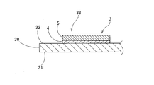
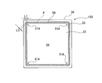
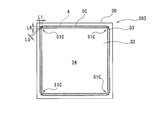
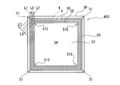
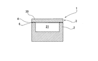
- FIG. 3 is a cross-sectional view of the package lid member taken along the line A1-A1 shown in FIG. It is a top view which shows the surface joined to a package substrate in the package lid material of 2nd Embodiment. It is a top view which shows the surface joined to a package substrate in the package lid material of 3rd Embodiment. It is a top view which shows the surface joined to a package substrate in the package lid material of 4th Embodiment.
- FIG. 1 is a perspective view showing a package substrate 2 and a package lid member 3 of this embodiment.
- FIG. 2 is a plan view of the package lid member 3.
- FIG. 3 is a cross-sectional view of the package lid member 3 taken along the line A1-A1 of FIG.
- FIG. 9 is a cross-sectional view of the package 1 formed by joining the package substrate 2 and the package lid member 3.
- the package 1 includes a package substrate 2 having a recess 21 having an open upper portion, and a flat plate-shaped package lid member 3 which is joined to the package substrate 2 to close the recess 21. Is equipped with.
- a light emitting element such as an LD (Laser Diode) or an LED (Light Emitting Diode) is housed in the package 1.
- the package substrate 2 has a recess 21 having an open upper portion, and a bonding surface 22 provided around the recess 21.
- the package substrate 2 is formed of AlN (aluminum nitride) or the like in a rectangular box shape.
- the recess 21 is closed by joining the package lid member 3 to the joining surface 22, and forms a space for housing the light emitting element and the like.
- the package lid member 3 includes a rectangular plate-shaped glass member 30 having a joining portion 33 provided in a plane frame shape and a light transmitting portion 34 provided inside the joining portion 33.
- the joint portion 33 has a frame-shaped metallization layer 4 and a frame-shaped Au—Sn layer 5 formed on the metallization layer 4.
- the joint portion 33 is also referred to as a frame line that surrounds the periphery of the light transmitting portion 34 including the substantially central portion of the glass member 30.
- the joint portion 33 defines the contour and area of the light transmitting portion 34.
- the metallized layer 4 and the Au—Sn layer 5 are also referred to as frame lines that surround the light transmitting portion 34. It is also said that the bonding portion 33, the metallized layer 4, and the Au—Sn layer 5 have a frame shape.
- the glass member 30 has an upper surface 31 that is the top surface of the package 1 and a lower surface 32 that includes a bonding portion 33 that is bonded to the bonding surface 22 of the package substrate 2.
- the glass member 30 is formed of borosilicate glass, quartz glass, or the like into a rectangular plate shape having a side of 2 mm to 30 mm and a thickness of 50 ⁇ m to 3000 ⁇ m.
- a rectangular frame-shaped metallized layer 4 made of Au, Ti, Ni or the like is formed on the bonding portion 33 of the lower surface 32.
- An Au—Sn layer 5 having the same rectangular frame shape as the metallized layer 4 is formed on the metallized layer 4.
- the metallized layer 4 is larger than the recess 21 of the package substrate 2 and is formed so as to surround the recess 21 and come into contact with the bonding surface 22.
- the width of the Au—Sn layer 5 is equal to or smaller than the width of the metallized layer 4, and is set to 250 ⁇ m or less.
- the area surrounded by the frame (frame line) of the metallized layer 4 is larger than the opening area above the recess 21 of the package substrate 2.
- the line width of the frame (frame line) of the Au—Sn layer 5 is the same as the line width of the frame (frame line) of the metallized layer 4, or is narrower than the line width of the frame (frame line) of the metallized layer 4.
- the line width of the Au—Sn layer 5 is set to 250 ⁇ m or less.
- the maximum width (maximum line width) L2 (The distance between the intersection of the outer two sides and the intersection of the two inner sides of the contour of the Au—Sn layer 5, that is, the maximum dimension in the direction intersecting the circumferential direction of the frame shape) is the portion excluding the four corners 51. Is larger than the width (line width) L1 of.
- the width L1 and the maximum width L2 are both 250 ⁇ m or less.
- the stress based on the difference in the linear expansion coefficient between the Au—Sn layer 5 and the glass member becomes large during cooling after the reflow for melting the Au—Sn layer 5, and the Au—Sn layer 5 increases. -The Sn layer 5 is peeled off from the glass member or the glass member is damaged.
- the width L1 and the maximum width L2 are preferably 50 ⁇ m or more. In this case, in the package 1 in which the package lid member 3 and the package substrate 2 are joined, the bond between the package lid member 3 and the package substrate 2 becomes strong, so that the package lid member 3 may come off from the package substrate 2. Absent.
- the width L1 of the portion (straight line portion) of the Au—Sn layer 5 excluding the corner portion 51 is set to 50 ⁇ m or more and 230 ⁇ m or less, and the maximum width L2 of the four corner portions 51 is set to 70 ⁇ m or more and 250 ⁇ m or less. I hope you are there.
- the height (thickness) of the Au—Sn layer 5 may be set to, for example, 1 ⁇ m or more and 100 ⁇ m or less.
- the light emitting element is housed in the recess 21 of the package substrate 2 described above.
- the Au—Sn layer 5 on the lower surface 32 of the package lid member 3 is brought into contact with the bonding surface 22 of the package substrate 2.
- the package substrate 2 and the package lid member 3 are reflowed (heated).
- the Au—Sn solder (bonding layer 6) formed by melting the Au—Sn layer 5 is formed.
- the package substrate 2 and the package lid member 3 are joined with this Au—Sn solder (joint layer 6) to form the package 1 as shown in FIG.
- the package lid 3 is manufactured, for example, as follows. On the surface of one glass member 30 (a plate material having a size of 20 mm ⁇ 20 mm in the present embodiment), a plurality of metallized layers 4 made of Au, Ti, Ni or the like by sputtering or plating (for example, the outer shape is 3 mm in length and width). 25 square frames) are formed. Next, an Au—Sn paste is applied so as to form a rectangular frame (for example, 25 square frames having an outer shape of 3 mm in length and width) on each metallized layer 4.
- a plurality of metallized layers 4 having a rectangular (square) frame shape are formed on the surface of the glass member 30. Then, an Au—Sn layer having a rectangular (square) frame shape is formed on each metallized layer 4. The Au—Sn layer is formed by applying an Au—Sn paste.
- the metallized layer 4 is preferably formed by Au plating.
- the metallized layer 4 is formed in the same rectangular frame shape as the Au—Sn layer 5.
- the Au—Sn paste forming the Au—Sn layer 5 has, for example, an Au—Sn alloy powder and a flux of 10% by mass or more and 90% by mass or less when the Au—Sn paste is 100% by mass. It is a mixture such that The Au—Sn alloy powder contains, for example, Sn in an amount of 21% by mass or more and 23% by mass or less, with the balance being Au and inevitable impurities.
- the flux is not particularly limited, a general soldering flux can be used.
- RA type, RMA type, non-halogen type flux, MSN type, AS1 type, AS2 type and the like can be used.
- the Au-Sn paste is applied by printing on the metallized layer 4 so that the coating film has a width of 50 ⁇ m or more and 250 ⁇ m or less and a thickness of 1 ⁇ m or more and 100 ⁇ m or less.
- the Au-Sn paste may be applied by being discharged and supplied by a dispenser or the like.
- the glass member 30 on which the Au—Sn paste is applied by printing is heated (reflow).
- the coating film of Au—Sn paste is heated in a non-oxidizing atmosphere such as an N 2 atmosphere.
- the heating temperature may be in the range of 280 ° C to 350 ° C, preferably in the range of 280 ° C to 330 ° C, more preferably in the range of 280 ° C to 300 ° C.
- the heating time may be maintained within the range of 10 seconds to 120 seconds at the heating temperature.
- the heating time is preferably in the range of 20 seconds to 90 seconds, more preferably 30 seconds to 60 seconds.
- An example of suitable conditions is a condition of heating at 300 ° C. for 1 minute.
- the linear expansion coefficient of the Au—Sn layer 5 formed by reflow is different from the linear expansion coefficient of the glass member 30. That is, the contraction rate of the Au—Sn layer 5 due to cooling is higher than that of the glass member. From this, when the stress acting on the glass member 30 due to the contraction of the Au—Sn layer 5 during cooling is large, the Au—Sn layer 5 may be peeled from the glass member 30 or a part of the glass member 30 may be peeled off. there's a possibility that.
- the width of the Au—Sn layer 5 is 250 ⁇ m or less, the stress acting on the glass member 30 due to the contraction of the Au—Sn layer 5 during cooling is small. This prevents the Au—Sn layer 5 from peeling off from the glass member 30 and damaging the glass member 30.
- the package lid 3 shown in FIGS. 2 to 3 is obtained.
- the package lid member 3 manufactured in this manner is bonded to the package substrate 2 as described above to form the package 1.
- the recess 21 of the package substrate 2 is reliably sealed by the package lid member 3 and the package substrate 2 is peeled off due to the stress caused by the contraction of the Au—Sn layer 5. Also, damage can be suppressed.
- FIG. 9 shows Package 1.
- the Au—Sn layer 5 is melted and then solidified to form the bonding layer 6.
- the package substrate 2 and the package lid member 3 are joined together with no gap by the joining layer 6.
- the present invention is not limited to the above embodiment, and various modifications can be made without departing from the requirements of the present invention.
- the second to eighth embodiments will be described, but the description of the same requirements as the first embodiment will be omitted.
- the width of the metallized layer and the Au—Sn layer is the line width of the frame (frame line) or the frame shape.
- FIG. 4 is a plan view showing the package lid member 103 according to the second embodiment.
- an Au—Sn layer 5A is provided instead of the Au—Sn layer 5.
- each rectangular frame-shaped corner portion 51A is chamfered. Therefore, the maximum width L3 of the four corners 51A (the maximum dimension of the corners of the frame forming the Au—Sn layer 5A in the direction intersecting the circumferential direction) is larger than the width L1 of the portion excluding the four corners 51A. small. That is, the width of any part of the Au—Sn layer 5A is 250 ⁇ m or less.
- the width L1 of a portion (straight portion) excluding the corner 51A is set to 50 ⁇ m or more and 250 ⁇ m or less, and the maximum width L3 of the four corners 51A is set to 30 ⁇ m or more and 130 ⁇ m or less.
- the Au—Sn layer 5A having such a shape may be formed by the following method.
- An Au—Sn layer is formed by forming a metallized layer 4 having the same shape as the Au—Sn layer 5A with chamfered corners, and applying Au—Sn paste on the metallized layer 4 with the same chamfered corners and reflowing. 5A may be formed.
- an Au—Sn layer is also formed in a rectangular frame shape without chamfering on the metallized layer 4 formed in a rectangular frame shape without chamfering, and then the corner portion 51A of the Au—Sn layer is chamfered to form an Au—Sn layer 5A. May be formed.
- FIG. 5 is a plan view showing the package lid member 203 according to the third embodiment.
- an Au—Sn layer 5B is provided instead of the Au—Sn layer 5.
- the four corner portions 51B having a rectangular frame shape have a shape in which the inside is cut out in a circular shape. Therefore, the maximum width L4 of the four corner portions 51B is smaller than the width L1 of the portion excluding the four corner portions 51B. That is, the width of any part of the Au—Sn layer 5B is 250 ⁇ m or less.
- the width L1 of the portion (straight part) excluding the corner 51B of the Au—Sn layer 5B is set to 50 ⁇ m or more and 230 ⁇ m or less, and the maximum width L4 of the four corners 51B is set to 30 ⁇ m or more and 130 ⁇ m or less. There is.
- the Au—Sn layer 5B having such a shape may be formed by the following method.
- the metallized layer 4 having a notch having the same shape as the Au—Sn layer 5B is formed, and Au—Sn paste is applied on the metallized layer 4 in the same shape as the notch and reflowed to form the Au—Sn layer 5B.
- Au—Sn layer is also formed on the metallization layer 4 formed in a rectangular frame shape without cutouts in the same rectangular frame shape without cutouts, and then the inside of the corner portion 51B of the Au—Sn layer is cut into a circular shape.
- the Au—Sn layer 5B may be omitted to form it.
- FIG. 6 is a plan view showing the package lid member 303 according to the fourth embodiment.
- an Au—Sn layer 5C is provided instead of the Au—Sn layer 5.
- the maximum width L5 of the two sides that intersect at the corner 51C is approximately half the width L1 of the portion (straight portion) of the Au—Sn layer 5C excluding the corner 51C.
- the two sides that intersect at the corner portion 51C are provided with regions (regions) whose width is approximately half the width L1 of the straight line portion.
- the distance L6 of the region whose width is substantially half of the width L1 of the linear portion is set within the range of 40 ⁇ m or more and 125 ⁇ m or less in consideration of the decrease in the bondability. There is.
- the maximum width L5 of the four corner portions 51C of the Au—Sn layer 5C is smaller than the width L1 of the straight portion of the Au—Sn layer 5C. That is, the width of any part of the Au—Sn layer 5C is 250 ⁇ m or less.
- the width L1 of the linear portion is set to 50 ⁇ m or more and 250 ⁇ m or less, and the maximum width L5 of the four corner portions 51C is set to 30 ⁇ m or more and 130 ⁇ m or less.
- FIG. 7 is a plan view showing a package lid member 403 according to the fifth embodiment.
- a frame-shaped first Au—Sn layer 5D and a frame-shaped second Au formed with a gap inside the first Au—Sn layer 5D.
- -Sn layer 5E instead of the Au—Sn layer 5, a frame-shaped first Au—Sn layer 5D and a frame-shaped second Au formed with a gap inside the first Au—Sn layer 5D. -Sn layer 5E.
- the width L1 of the first Au—Sn layer 5D and the maximum width (maximum line width) L2 at the corner 51, and the width L7 of the second Au—Sn layer 5E and the maximum width (maximum line width) L8 at the corner 51E are It is set to 250 ⁇ m or less.
- the first Au—Sn layer 5D is the same as the Au—Sn layer 5 of the first embodiment.
- the width L7 of the linear portion is set to 50 ⁇ m or more and 250 ⁇ m or less, and the maximum width L8 of the four corner portions 51E is set to 70 ⁇ m or more and 250 ⁇ m or less.
- the distance L9 between the first Au—Sn layer 5D and the second Au—Sn layer 5E is set to 10 ⁇ m or more and 500 ⁇ m or less.
- the package cover material 403 to the Au—Sn layer 5D due to the contraction of the molten Au—Sn. 5E can be prevented from peeling off.
- the bonding range by the Au—Sn layer can be expanded as compared with the package cover material of the first to fourth embodiments, so the package cover The material 403 can increase the bonding strength when the package substrate 2 is sealed.
- each Au—Sn layer is formed in a rectangular frame shape, but the present invention is not limited to this.
- the frame-shaped Au—Sn layer may have a triangular shape, a hexagonal shape, or a circular shape without corners.
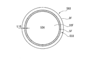
- FIG. 8 is a plan view showing a package lid member 503 according to the sixth embodiment.
- the package lid 503 has a circular glass member 3F instead of the rectangular glass member 30 and a circular frame-shaped instead of the rectangular frame-shaped metallized layer 4 and Au—Sn layer 5. It has a metallization layer (not shown) and a circular frame-shaped Au—Sn layer 5F.
- the glass member 3F has a central light transmitting portion 534 and a circular frame-shaped joining portion 533 surrounding the light transmitting portion 534.
- the Au—Sn layer 5F is formed in a circular shape with no corners at the joint 533.
- the width L10 of the Au—Sn layer 5F is 250 ⁇ m or less.
- the width L10 of the Au—Sn layer 5F is set to 50 ⁇ m or more and 250 ⁇ m or less.
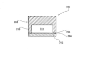
- FIG. 10 is a sectional view showing a package 701 according to the seventh embodiment.
- the recess 731 is provided in the glass member 730 of the package lid member 703 instead of the package substrate 702.
- the package cover 703 includes a glass member 730, a frame-shaped metallized layer 704 formed on the glass member 730, and a frame-shaped Au—Sn layer formed on the metallized layer 704.
- the package lid member 703 is joined to the flat package substrate 702 by the joining layer 706 formed by melting and solidifying the Au—Sn layer to form the package 701.
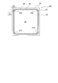
- FIG. 11 is a plan view showing a package lid member 803 according to the eighth embodiment.
- a metallized layer 4G having arcuate corners instead of the metallized layer 4 and an Au—Sn layer 5G having arcuate corners 51G instead of the Au—Sn layer 5 are provided.
- the Au-Sn layer 5G is formed with the same (constant) width L8 as a whole including the corner portion 51G.
- Example 1 Au plating was applied to the surface of a rectangular glass member having a size of 20 mm ⁇ 20 mm to form a metallized layer of 25 samples.
- the metallized layer had a rectangular frame shape with the same dimensions as the Au—Sn layer shown in Table 1 and had a thickness of 0.1 ⁇ m.
- Au-Sn paste was applied in the same rectangular frame shape as the metallized layer.
- the Au—Sn paste was obtained by mixing Au—Sn alloy powder and flux at a flux ratio of 10 mass%.
- the Au—Sn alloy powder (Au-22 mass% Sn alloy powder) contained 22 mass% Sn, and the balance was Au and inevitable impurities. RA type was used as the flux.
- Example 1 and Comparative Example the Au-Sn of the package size 3030 (length 3.0 mm ⁇ width 3.0 mm) in the shape of the eighth embodiment shown in FIG.
- a Au-Sn paste was screen-printed and applied on the glass member using a printing mesh mask having a thickness of 30 ⁇ m.
- Example 2 since the Au—Sn layer having the shape of the second embodiment shown in FIG. 4 and having the package size 3030 (length 3.0 mm ⁇ width 3.0 mm) having the dimensions shown in Table 1 is formed, the thickness is changed.
- An Au—Sn paste was screen-printed and applied on the glass member using a printing mesh mask having a thickness of 30 ⁇ m.
- the glass member coated with the Au—Sn paste was reflowed to form 25 frame-shaped Au—Sn layers on the glass member.
- the coating film of Au—Sn paste was heated at 300 ° C. for 1 minute in an N 2 atmosphere.
- the width of the portion (straight portion) excluding the corner portion and the maximum width of the corner portion are the values shown in Table 1, and the thickness of the Au—Sn layer is 4.7 ⁇ m. there were.
- Example 1 In Examples 1 and 2 in which the width of the Au—Sn layer was 250 ⁇ m or less, the peeling evaluation was 92% or more. In particular, in Example 2, the peeling evaluation was 96%, and the peeling evaluation was particularly high in Example 2 in which the width of the corner portion was 100 ⁇ m and was equal to or smaller than that of the straight portion. On the other hand, in Comparative Example 1, since the width of the Au—Sn layer was as large as 425 ⁇ m, about half of the Au—Sn layer was peeled off, and the peeling evaluation was as low as 48%.
- the package cover material and the package of the present embodiment can be suitably applied to a semiconductor device and a light emitting device in which a light emitting element such as a semiconductor laser (LD) or an LED is sealed in the package.
- a light emitting element such as a semiconductor laser (LD) or an LED is sealed in the package.
Landscapes
- Physics & Mathematics (AREA)
- Condensed Matter Physics & Semiconductors (AREA)
- General Physics & Mathematics (AREA)
- Electromagnetism (AREA)
- Optics & Photonics (AREA)
- Engineering & Computer Science (AREA)
- Mechanical Engineering (AREA)
- Chemical & Material Sciences (AREA)
- Materials Engineering (AREA)
- Metallurgy (AREA)
- Organic Chemistry (AREA)
- Piezo-Electric Or Mechanical Vibrators, Or Delay Or Filter Circuits (AREA)
- Microelectronics & Electronic Packaging (AREA)
Abstract
Matériau de couvercle pour emballages lié à un substrat d'emballage et comprenant : un élément en verre qui est pourvu d'une partie de liaison disposée selon une forme de cadre plan et d'une partie de transmission de lumière disposée à l'intérieur de la partie de liaison ; une ou plusieurs couches métallisées qui sont agencées sous une forme de cadre sur la partie de liaison de l'élément en verre ; et une ou plusieurs couches Au-Sn qui sont disposées au-dessus des couches métallisées, tout en présentant une forme de cadre d'une largeur de 250 µm ou moins.
Priority Applications (5)
| Application Number | Priority Date | Filing Date | Title |
|---|---|---|---|
| KR1020207035590A KR102334781B1 (ko) | 2018-10-15 | 2019-10-09 | 패키지용 뚜껑재 및 패키지 |
| CN202210506101.0A CN114864785B (zh) | 2018-10-15 | 2019-10-09 | 封装用盖部件及封装体的制造方法 |
| CN201980059130.3A CN112673534B (zh) | 2018-10-15 | 2019-10-09 | 封装用盖部件及封装体 |
| EP19872989.9A EP3809541B1 (fr) | 2018-10-15 | 2019-10-09 | Matériau de couvercle pour emballages, et emballage |
| US17/260,276 US11158766B2 (en) | 2018-10-15 | 2019-10-09 | Lid material for packages including reflowed gold-tin layers, and method for manufacturing package |
Applications Claiming Priority (4)
| Application Number | Priority Date | Filing Date | Title |
|---|---|---|---|
| JP2018194535 | 2018-10-15 | ||
| JP2018-194535 | 2018-10-15 | ||
| JP2019-184287 | 2019-10-07 | ||
| JP2019184287A JP6784317B2 (ja) | 2018-10-15 | 2019-10-07 | パッケージ用蓋材及びパッケージの製造方法 |
Publications (1)
| Publication Number | Publication Date |
|---|---|
| WO2020080221A1 true WO2020080221A1 (fr) | 2020-04-23 |
Family
ID=70283452
Family Applications (1)
| Application Number | Title | Priority Date | Filing Date |
|---|---|---|---|
| PCT/JP2019/039826 Ceased WO2020080221A1 (fr) | 2018-10-15 | 2019-10-09 | Matériau de couvercle pour emballages, et emballage |
Country Status (3)
| Country | Link |
|---|---|
| KR (1) | KR102334781B1 (fr) |
| CN (2) | CN112673534B (fr) |
| WO (1) | WO2020080221A1 (fr) |
Citations (8)
| Publication number | Priority date | Publication date | Assignee | Title |
|---|---|---|---|---|
| JPS6260919B2 (fr) | 1981-01-21 | 1987-12-18 | Tokyo Shibaura Electric Co | |
| US20060164631A1 (en) * | 2005-01-21 | 2006-07-27 | Samsung Electronics Co., Ltd. | Optical scanner package having heating dam |
| JP2008147234A (ja) * | 2006-12-06 | 2008-06-26 | Denso Corp | 半導体基板のキャップ固着方法 |
| JP2011040577A (ja) * | 2009-08-11 | 2011-02-24 | Citizen Electronics Co Ltd | 発光装置の製造方法 |
| US20150014711A1 (en) * | 2012-01-11 | 2015-01-15 | Osram Gmbh | Optoelectronic component with inert gas atmosphere |
| JP6294417B2 (ja) | 2016-09-01 | 2018-03-14 | 日機装株式会社 | 光半導体装置および光半導体装置の製造方法 |
| JP2018194535A (ja) | 2016-08-09 | 2018-12-06 | 東ソー株式会社 | 繊維状物質を用いる検出方法 |
| JP2019184287A (ja) | 2018-04-03 | 2019-10-24 | Tdk株式会社 | 温度センサ装置 |
Family Cites Families (8)
| Publication number | Priority date | Publication date | Assignee | Title |
|---|---|---|---|---|
| JPH06294417A (ja) | 1993-04-06 | 1994-10-21 | Nippon Seiko Kk | 電食防止転がり軸受 |
| JPH0936690A (ja) * | 1995-07-20 | 1997-02-07 | S I I Quartz Techno:Kk | 薄型水晶振動子 |
| JP3647289B2 (ja) * | 1998-11-02 | 2005-05-11 | キヤノン株式会社 | ガラス外囲器の製造方法 |
| JP5836796B2 (ja) * | 2011-12-28 | 2015-12-24 | 日本特殊陶業株式会社 | セラミックパッケージ |
| JP6167494B2 (ja) * | 2012-09-26 | 2017-07-26 | セイコーエプソン株式会社 | 電子デバイス用容器の製造方法、電子デバイスの製造方法、電子デバイス、電子機器及び移動体機器 |
| JP6314406B2 (ja) * | 2013-10-03 | 2018-04-25 | 日立金属株式会社 | 気密封止用キャップ、電子部品収納用パッケージおよび気密封止用キャップの製造方法 |
| JP6373115B2 (ja) * | 2014-08-05 | 2018-08-15 | 日本特殊陶業株式会社 | 配線基板 |
| JP2018152385A (ja) * | 2017-03-09 | 2018-09-27 | 日本山村硝子株式会社 | 低温封止部材及びその製造方法 |
-
2019
- 2019-10-09 CN CN201980059130.3A patent/CN112673534B/zh active Active
- 2019-10-09 WO PCT/JP2019/039826 patent/WO2020080221A1/fr not_active Ceased
- 2019-10-09 CN CN202210506101.0A patent/CN114864785B/zh active Active
- 2019-10-09 KR KR1020207035590A patent/KR102334781B1/ko active Active
Patent Citations (8)
| Publication number | Priority date | Publication date | Assignee | Title |
|---|---|---|---|---|
| JPS6260919B2 (fr) | 1981-01-21 | 1987-12-18 | Tokyo Shibaura Electric Co | |
| US20060164631A1 (en) * | 2005-01-21 | 2006-07-27 | Samsung Electronics Co., Ltd. | Optical scanner package having heating dam |
| JP2008147234A (ja) * | 2006-12-06 | 2008-06-26 | Denso Corp | 半導体基板のキャップ固着方法 |
| JP2011040577A (ja) * | 2009-08-11 | 2011-02-24 | Citizen Electronics Co Ltd | 発光装置の製造方法 |
| US20150014711A1 (en) * | 2012-01-11 | 2015-01-15 | Osram Gmbh | Optoelectronic component with inert gas atmosphere |
| JP2018194535A (ja) | 2016-08-09 | 2018-12-06 | 東ソー株式会社 | 繊維状物質を用いる検出方法 |
| JP6294417B2 (ja) | 2016-09-01 | 2018-03-14 | 日機装株式会社 | 光半導体装置および光半導体装置の製造方法 |
| JP2019184287A (ja) | 2018-04-03 | 2019-10-24 | Tdk株式会社 | 温度センサ装置 |
Also Published As
| Publication number | Publication date |
|---|---|
| CN112673534B (zh) | 2022-05-27 |
| CN114864785B (zh) | 2025-06-03 |
| CN114864785A (zh) | 2022-08-05 |
| CN112673534A (zh) | 2021-04-16 |
| KR102334781B1 (ko) | 2021-12-02 |
| KR20210002730A (ko) | 2021-01-08 |
Similar Documents
| Publication | Publication Date | Title |
|---|---|---|
| CN109690796B (zh) | 光半导体装置以及光半导体装置的制造方法 | |
| JP6784317B2 (ja) | パッケージ用蓋材及びパッケージの製造方法 | |
| TWI857960B (zh) | 封裝、封裝製造方法、附接合材之蓋體及附接合材之蓋體的製造方法 | |
| JP2024052748A (ja) | 窓材、光学パッケージ | |
| KR20090127251A (ko) | 기밀 밀봉용 캡, 전자 부품 수납용 패키지 및 전자 부품 수납용 패키지의 제조 방법 | |
| CN112673467B (zh) | 封装用盖部件的制造方法及封装体的制造方法 | |
| CN112673534B (zh) | 封装用盖部件及封装体 | |
| HK40070310A (en) | Lid component for packages and package manufacturing method | |
| GB2036794A (en) | Solder Preform | |
| JPH04186688A (ja) | 半導体レーザ装置 | |
| HK40070310B (en) | Lid component for packages and package manufacturing method | |
| KR102263552B1 (ko) | 패키지용 덮개재의 제조 방법 및 패키지의 제조 방법 | |
| JP7298609B2 (ja) | 蓋部材の製造方法、蓋部材、及び電子部品パッケージの製造方法 | |
| JP7473877B2 (ja) | 蓋部材の製造方法 | |
| WO2020022278A1 (fr) | Boîtier optique | |
| HK40047559A (en) | Method for manufacturing package lid member and method for manufacturing package | |
| HK40047559B (en) | Method for manufacturing package lid member and method for manufacturing package |
Legal Events
| Date | Code | Title | Description |
|---|---|---|---|
| 121 | Ep: the epo has been informed by wipo that ep was designated in this application |
Ref document number: 19872989 Country of ref document: EP Kind code of ref document: A1 |
|
| ENP | Entry into the national phase |
Ref document number: 20207035590 Country of ref document: KR Kind code of ref document: A |
|
| ENP | Entry into the national phase |
Ref document number: 2019872989 Country of ref document: EP Effective date: 20210112 |
|
| NENP | Non-entry into the national phase |
Ref country code: DE |