WO2020080329A1 - Bec verseur et poche équipée d'un bec verseur - Google Patents
Bec verseur et poche équipée d'un bec verseur Download PDFInfo
- Publication number
- WO2020080329A1 WO2020080329A1 PCT/JP2019/040377 JP2019040377W WO2020080329A1 WO 2020080329 A1 WO2020080329 A1 WO 2020080329A1 JP 2019040377 W JP2019040377 W JP 2019040377W WO 2020080329 A1 WO2020080329 A1 WO 2020080329A1
- Authority
- WO
- WIPO (PCT)
- Prior art keywords
- pouch
- spout
- flange
- end surface
- back direction
- Prior art date
- Legal status (The legal status is an assumption and is not a legal conclusion. Google has not performed a legal analysis and makes no representation as to the accuracy of the status listed.)
- Ceased
Links
Images

















Classifications
-
- B—PERFORMING OPERATIONS; TRANSPORTING
- B65—CONVEYING; PACKING; STORING; HANDLING THIN OR FILAMENTARY MATERIAL
- B65D—CONTAINERS FOR STORAGE OR TRANSPORT OF ARTICLES OR MATERIALS, e.g. BAGS, BARRELS, BOTTLES, BOXES, CANS, CARTONS, CRATES, DRUMS, JARS, TANKS, HOPPERS, FORWARDING CONTAINERS; ACCESSORIES, CLOSURES, OR FITTINGS THEREFOR; PACKAGING ELEMENTS; PACKAGES
- B65D75/00—Packages comprising articles or materials partially or wholly enclosed in strips, sheets, blanks, tubes or webs of flexible sheet material, e.g. in folded wrappers
- B65D75/52—Details
- B65D75/58—Opening or contents-removing devices added or incorporated during package manufacture
- B65D75/5861—Spouts
- B65D75/5872—Non-integral spouts
- B65D75/5883—Non-integral spouts connected to the package at the sealed junction of two package walls
-
- B—PERFORMING OPERATIONS; TRANSPORTING
- B65—CONVEYING; PACKING; STORING; HANDLING THIN OR FILAMENTARY MATERIAL
- B65D—CONTAINERS FOR STORAGE OR TRANSPORT OF ARTICLES OR MATERIALS, e.g. BAGS, BARRELS, BOTTLES, BOXES, CANS, CARTONS, CRATES, DRUMS, JARS, TANKS, HOPPERS, FORWARDING CONTAINERS; ACCESSORIES, CLOSURES, OR FITTINGS THEREFOR; PACKAGING ELEMENTS; PACKAGES
- B65D2231/00—Means for facilitating the complete expelling of the contents
- B65D2231/001—Means for facilitating the complete expelling of the contents the container being a bag
-
- B—PERFORMING OPERATIONS; TRANSPORTING
- B65—CONVEYING; PACKING; STORING; HANDLING THIN OR FILAMENTARY MATERIAL
- B65D—CONTAINERS FOR STORAGE OR TRANSPORT OF ARTICLES OR MATERIALS, e.g. BAGS, BARRELS, BOTTLES, BOXES, CANS, CARTONS, CRATES, DRUMS, JARS, TANKS, HOPPERS, FORWARDING CONTAINERS; ACCESSORIES, CLOSURES, OR FITTINGS THEREFOR; PACKAGING ELEMENTS; PACKAGES
- B65D2575/00—Packages comprising articles or materials partially or wholly enclosed in strips, sheets, blanks, tubes or webs of flexible sheet material, e.g. in folded wrappers
- B65D2575/52—Details
- B65D2575/58—Opening or contents-removing devices added or incorporated during package manufacture
- B65D2575/583—Opening or contents-removing devices added or incorporated during package manufacture the non-integral spout having an elongate cross-sectional shape, e.g. canoe or boat shaped
Definitions
- the present invention relates to a spout attached to a pouch and a pouch with a spout.
- a pouch formed into a bag shape by heat-sealing stacked films as a container for storing contents having viscosity and fluidity such as jelly-like beverages
- a spout having a spout hole can be attached to the spout of such a pouch to make it possible to easily spout the contents.
- the pouch is moved from the outer side to the inner side in the left-right direction to the front film portion and the back film portion.
- the film contact area R in which the film adheres to each other expands, and such left and right film contact areas R are connected or almost connected in the vicinity of the center of the pouch left-right direction.
- the left and right film contact regions R are connected or almost connected, it becomes difficult to pour out the contents remaining on the bottom portion 124 of the pouch below the connected film contact regions R.
- the spout having the flange portion protruding to the outer peripheral side as disclosed in Patent Document 2 has the following problems.
- the user grasps the flange portion formed above the attachment portion with the finger of one hand and the finger of the other hand.
- the cap may be rotated while holding the cap with.
- the thickness of the flange portion in the up-down direction is generally thin, the flange portion may bite into the finger holding the flange portion, causing the user to feel pain or discomfort. There was such a problem.
- the present invention solves these problems, and an object thereof is to provide a convenient spout and a pouch with a spout with a simple structure.
- the spout of the present invention is a spout that includes an attachment portion that is attached to the pouch, and an extension portion that extends downward from the attachment portion and that forms a flow path for contents inside the pouch.
- the extending portion has a portion in which the shape when viewed from the lower side is asymmetrical in the front-back direction of the pouch when an imaginary line parallel to the left-right direction of the pouch is used as a reference. By having it in a partial area, the above problem is solved.
- the pouch with a spout of the present invention solves the above problem by including the spout and a pouch that has a front film portion and a back film portion and is attached to the attachment portion.
- a spout according to another aspect of the present invention is a spout attached to a pouch, one or more flanges formed above the attachment, and a spout formed on the attachment and extending in a vertical direction.
- the first flange portion faces a first front side flange end surface facing the front side in the front and back direction of the pouch and a back side in the front and back direction of the pouch.
- a first back side flange end surface, and the first front side flange end surface is outside the front and back sides of the pouch more than the front side mounting portion end surface at a central position corresponding to the center axis of the pouring hole in the left and right direction of the pouch.
- a spout according to another aspect of the present invention is a mounting portion mounted on a pouch, one or more flange portions formed above the mounting portion, and a vertical portion formed on the mounting portion.
- a spout having a pouring hole wherein the one or more flange portions include a first flange portion formed at a lowermost portion, and the attachment portion is a front side facing a front side in a front-back direction of the pouch. It has a mounting portion end surface and a back side mounting portion end surface facing the back side in the front and back direction of the pouch, and the first flange portion has a first front side flange end surface facing the front side in the front and back direction of the pouch and a back side in the front and back direction of the pouch.
- first back-side flange end surface that faces the pouch front-back surface rather than the front-side mounting portion end surface at a central position corresponding to the central axis of the pouring hole in the pouch left-right direction.
- the first back side flange end surface at the central position, the back side mounting portion end surface inside the pouch front and back direction, or the The problem is solved by being located at the same position in the front and back direction of the pouch as the end surface of the back side mounting portion.
- a pouch with a spout is a pouch with a spout that includes the spout and a pouch that has a front film portion and a back film portion and is attached to the attachment portion, and the distance D1. Is set to be equal to or larger than the thickness dimension T1 of the front side film portion, and the distance D2 is set to be equal to or larger than the thickness dimension T2 of the back side film portion, thereby solving the above problem.
- the shape when viewed from below is asymmetrical in the front and back direction of the pouch.
- the deformed state of each film portion such as wrinkles due to contact with the extended portion at the time of reducing the remaining amount of the content, and the front film portion. It can be different from the back film part.
- the left and right film contact regions where the front film portion and the back film portion are in contact with each other are expanded in the vicinity of the center of the pouch in the left-right direction. Since it is possible to suppress or delay the phenomenon of being connected or almost connected with each other, it is possible to prevent the contents from being enclosed in the bottom portion of the pouch below the film adhesion region and to pour out the contents well. be able to.
- the shape when viewed from below is asymmetrically formed in the left and right direction of the pouch.
- the pouch can be changed in the left and right directions with and. Thereby, it is possible to shift the position of the vertical wrinkles formed in the front film portion and the position of the vertical wrinkles formed in the back film portion due to the contact with the extension portion in the left-right direction of the pouch.
- the shape when viewed from the lower side of the lower end portion of the extending portion is formed asymmetrically in the front-back direction of the pouch and in the left-right direction of the pouch, so that the contents described above can be obtained. Since the deformed state of each film portion due to contact with the extended portion at the time of reducing the remaining amount can be easily obtained in the area below the extended portion, the above-mentioned is also described in the area below the extended portion. It is possible to suppress the phenomenon that the left and right film contact regions are connected or almost connected near the center of the pouch in the left-right direction.
- the extension portion in the vertical direction since it is possible to control the deformation state of each film portion in the area below the extension portion, it is possible to design the extension portion in the vertical direction to have a short dimension.
- the extended portion does not prevent the front side film portion and the back side film portion from being in close contact with each other in the area lower than the extended portion, the contents remaining in the area lower than the extended portion Can be reduced.
- the tip of the extension part is prevented from coming into contact with the bottom part of the pouch, the bag is broken near the bottom, or the extension part itself is broken. Prevent things. Further, it becomes possible to reduce the material cost and weight of the spout.
- the extending portion has a front side vertical wrinkle forming portion extending in a direction in which the extending portion extends on a side of the pouch facing the front side film portion of the extending portion and at least on the downstream side.
- a back side vertical wrinkle forming part extending in a direction in which the extending part extends, and at least a downstream side of the extending part facing the back side film part of the pouch, and a front side vertical wrinkle forming part and a back side of the extending part.
- the vertical wrinkle forming portion is formed at a position displaced from each other in the left-right direction of the pouch.
- the extending portion has the curved portion formed by curving the plate-shaped member, so that the remaining amount of the content is in the middle of the content pouring.
- the extending portion has a twisted portion formed by twisting the plate member so that the upper end and the lower end of the plate member form an angle. In the middle of pouring the contents, even if each film part is in contact with the twist part, it is possible to form a gap between the twisted twist part and each film part.
- the contents can be satisfactorily poured out by using as a flow path, and at the final stage of the contents pouring, each film part is brought into close contact or almost close contact with the outer surface of the twist part, and the gap is Since it can be eliminated or narrowed, the amount of contents remaining in the gap can be reduced. Further, by forming the twisted portion in a twisted shape of the plate-shaped member so that the upper end and the lower end of the plate-shaped member form an angle, the twisted portion is formed between the upper end and the lower end of the twisted part with a simple configuration.
- the lower end of the extension part Since it is possible to adjust the relationship of the orientation of the pouch, it is possible to arrange the lower end of the extension part so that the lower end part of the extension part is asymmetrical in the lateral direction of the pouch and the front-back direction of the pouch, regardless of the aspect of the upper end side of the extension part. For example, it is possible to easily adjust the direction of the lower end portion side of the extended portion. Further, since the rigidity of the extended portion can be improved by forming the extended portion from the twisted portion in which the plate member is twisted, the extension portion is extended in the pouch due to the user's operation or the like. It is possible to prevent the installation portion from being damaged.
- the curved portion is formed in at least the lower region of the extension portion, when the spout is manufactured by injection molding, the degree of freedom in design above the extension portion can be increased. It is possible to increase the height, and it is not necessary to take special consideration in the mold manufacturing, such as the position of the gate and the alignment of the molds, and the mold manufacturing can be facilitated.
- the first front-side flange end surface and the first back-side flange end surface are located at the central position corresponding to the central axis of the pouring hole in the left-right direction of the pouch, and thus the front-side mounting portion end surface or the back-side mounting portion end surface.
- the distance D1 in the pouch front-back direction between the front-side mounting portion end surface and the first front-side flange end surface at the central position is set within 0.5 mm
- the distance D2 in the pouch front-back direction between the back-side mounting portion end surface and the first back-side flange end surface at the central position is set within 0.5 mm.
- the step between the mounting portion and the first flange portion becomes small, and when the user grips the spout with his / her finger when the cap is opened / closed, the user grips both the mounting portion and the first flange portion. Since it is easy to do so, it is possible to suppress the first flange portion from biting into the user's finger, and it is possible to stably grip the spout without causing the user to feel pain or discomfort. Moreover, since the amount of material of the first flange portion can be reduced, the manufacturing cost can be reduced.
- the distance D1 in the pouch front-back direction between the end surface of the front-side mounting portion and the end surface of the first front-side flange is set to be equal to or greater than the thickness dimension T1 of the front-side film portion
- the back-side mounting portion end surface is By setting the distance D2 in the front and back direction of the pouch between the first end and the end surface of the first flange to be equal to or more than the thickness dimension T2 of the back film portion, when the user grips the spout with the finger, the finger of the user is the front film. Since it is possible to suppress hitting the edge and the edge of the backside film, the spout can be gripped without causing the user to feel pain or discomfort.
- the distance D1 in the front and back direction of the pouch between the end surface of the front mounting portion and the end surface of the first front flange is 1.0 to 3.0 times the thickness dimension T1 of the front film portion.
- the distance D2 in the front and back direction of the pouch between the end surface of the back side mounting portion and the end surface of the first back side flange is set to 1.0 to 3.0 times the thickness dimension T2 of the back side film portion, so that the user When the user grips the spout with his / her finger, the user's finger may touch the so-called poly pool formed by melting the adhesive layer of each film part when welding each film part to the attachment part of the spout. Can be suppressed.
- the first front-side flange end surface is located at the center position inward of the front-side mounting portion end surface in the front-back direction of the pouch or at the same position in the front-side mounting portion end surface as the front-back direction of the pouch.
- the first back-side flange end surface is located at the center position inside the back-side mounting portion end surface in the front-back direction of the pouch or at the same position in the back-side mounting portion end surface as the pouch front-back direction.
- At least one of the first front-side flange end surface and the first back-side flange end surface is relative to the cap portion when the cap is opened relative to the cap portion when the cap is opened, rather than the central position in the left-right direction of the pouch.
- the flat portion of each of the second flange bulging portions formed in parallel to the left and right direction and the vertical direction of the pouch is the maximum of the flange bulging portion of the first flange portion in the front and back direction of the pouch.
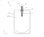
- Explanatory drawing which shows the pouch with a spout which concerns on 1st Embodiment of this invention.
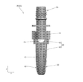
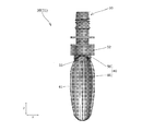
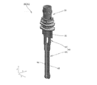
- Explanatory drawing which shows the spout which concerns on 1st Embodiment seen from the pouch front-back direction.
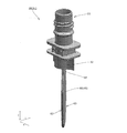
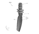
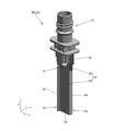
- Explanatory drawing which shows the spout which concerns on 1st Embodiment seen diagonally.
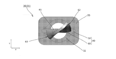
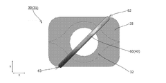
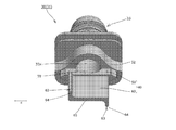
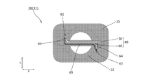
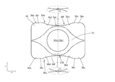
- Explanatory drawing which shows the spout which concerns on 1st Embodiment seen from a lower part.
- Explanatory drawing which shows roughly the state of each part at the time of the content pouring of 1st Embodiment.
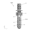
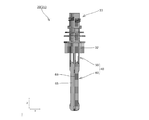
- Explanatory drawing which shows the spout which concerns on 2nd Embodiment seen from the pouch front-back direction.
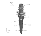
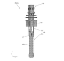
- Explanatory drawing which shows the spout which concerns on 2nd Embodiment seen diagonally. Explanatory drawing which shows the flow path formation part of the spout which concerns on 2nd Embodiment in sectional view. Explanatory drawing which shows the spout which concerns on 2nd Embodiment seeing from below. Explanatory drawing which shows the spout which concerns on 3rd Embodiment seen from the pouch front-back direction. Explanatory drawing which shows the spout which concerns on 3rd Embodiment seen diagonally. Explanatory drawing which shows the flow path formation part of the spout which concerns on 3rd Embodiment in sectional view. Explanatory drawing which shows the spout which concerns on 3rd Embodiment seen from lower direction.
- FIG. 20 is an explanatory view showing the spout according to the fifth embodiment as viewed obliquely from an angle different from FIG. 19.
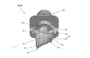
- Explanatory drawing which shows the spout which concerns on 5th Embodiment seeing from below.
- Explanatory drawing which shows the spout which concerns on 6th Embodiment seen from the pouch front-back direction.
- Explanatory drawing which shows the spout which concerns on 6th Embodiment seen diagonally.
- Explanatory drawing which shows the spout which concerns on 7th Embodiment seen from the pouch front-back direction Explanatory drawing which shows the spout which concerns on 7th Embodiment seen diagonally.
- Explanatory drawing which shows the flow path formation part of the spout which concerns on 7th Embodiment in sectional view. Explanatory drawing which shows the spout which concerns on 7th Embodiment seeing from below. Explanatory drawing which shows the spout which concerns on 8th Embodiment seen from the pouch front-back direction. Explanatory drawing which shows the spout which concerns on 8th Embodiment from the opposite side to FIG. 29 seeing from the front-back direction of a pouch. Explanatory drawing which shows the spout which concerns on 8th Embodiment seen diagonally. Explanatory drawing which shows the flow path formation part of the spout which concerns on 8th Embodiment in sectional view.
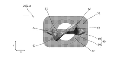
- Explanatory drawing which shows the spout which concerns on 8th Embodiment seeing from below.
- Explanatory drawing which shows the spout which concerns on 9th Embodiment seen from the pouch front-back direction.
- Explanatory drawing which shows the spout which concerns on 9th Embodiment seeing diagonally.
- Explanatory drawing which shows the flow path formation part of the spout which concerns on 9th Embodiment in sectional view.
- Explanatory drawing which shows the spout which concerns on 9th Embodiment seeing from below.
- Explanatory drawing which shows the pouch with a spout which concerns on 10th Embodiment of this invention.
- Explanatory drawing which shows the spout main body as seen from the front and back sides of the pouch.
- Explanatory drawing which shows the dimensional relationship of a 1st flange part and a mounting part seen from an upper part.
- Explanatory drawing which shows the dimensional relationship of a 2nd flange part and a mounting part seen from an upper part.
- Explanatory drawing which shows the modification of a 1st flange part or a 2nd flange part.
- Explanatory drawing which shows the modification of a 2nd flange part.
- the spout-equipped pouch 10 is configured by attaching a spout 30 functioning as a spout to a pouch 20 formed in a bag shape by heat-sealing stacked films at a predetermined location, and forming a jelly. It contains a viscous content such as a beverage or a fluid content such as a liquid or a sherbet (content liquid).
- the spout 30 is made of a synthetic resin or the like, and as shown in FIG. 1, has a spout body 31 attached to the pouch 20, and a cap portion 37 detachably attached to the spout body 31.
- the spout body 31 has a boat-shaped cross section (specifically, the spout body 31 protrudes outward from the both ends of the pouch left-right direction X in the cylindrical portion toward the outside of the pouch left-right direction X). (A shape in which a substantially triangular protrusion is formed) or a rhombus-shaped mounting portion 32, a spout cylinder portion 33 extending upward from the mounting portion 32, and a space above each other above the mounting portion 32. It integrally has a plurality of formed flange portions 35 and 36, and an extending portion 40 that extends downward from the attachment portion 32 and that is disposed inside the pouch 20 (content storage portion 23).
- the mounting portion 32 is disposed between the front side film portion 21 and the back side film portion 22 of the pouch 20 in a state in which the longitudinal direction thereof is oriented in the pouch left-right direction X, and heat attachment or It is a portion that is fixed to the front film portion 21 and the back film portion 22 by adhesion or the like.
- the mounting portion 32 has a round hole-shaped pouring hole 32a formed along the vertical direction Z.
- the spouting tube portion 33 is a cylindrical portion having a spouting hole 32a of the mounting portion 32 and a round hole-shaped spouting hole 33a continuous in the up-down direction Z.
- a screw capable of engaging with the cap portion 37 is provided on the upper end side (above the second upper flange portion 36) of the spout tube portion 33.
- the portion 33b is formed on the upper end side (above the second upper flange portion 36) of the spout tube portion 33.
- the plurality of flange portions 35, 36 have a first flange portion 35 formed at the bottom (formed closest to the mounting portion 32) and an upper portion of the first flange portion 35.
- a plurality of (two in the present embodiment) second flange portions 36 that are formed are included.
- the extension portion 40 is a portion for forming a flow path for contents inside the pouch 20 (contents storage portion 23), and as shown in FIGS. 1 to 4, below the attachment portion 32.
- the upper base portion 50 is continuously formed, and the flow path forming portion 60 is continuously formed below the upper base portion 50.
- the upper side base portion 50 is formed in a flat plate shape (or a substantially flat plate shape) and is integrally formed on the lower surface of the mounting portion 32 in a state parallel to the pouch left-right direction X and the vertical direction Z. There is. As shown in FIGS. 1 to 4, the upper side base portion 50 is formed with a through hole 51 penetratingly formed in the thickness direction thereof (pouch front-back direction Y) and communicating with the pouring hole 32a of the mounting portion 32. There is.
- the flow path forming portion 60 is composed of a twist portion (curving portion) 61 having a shape in which a plate-shaped member is curved so as to be twisted.
- the twist portion 61 has a substantially rectangular shape and a flat plate shape (or a substantially flat plate shape) in which R portions for reducing damage due to contact with the bag are formed at both corners on the lower end side thereof.
- a predetermined angle 45 ° in the present embodiment
- the plate-like members are evenly twisted so that they form a predetermined angle (45 ° in the present embodiment).
- the upper end portion of the twist portion 61 is integrally formed with the lower end surface of the upper base portion 50 with its longitudinal direction oriented in the pouch left-right direction X. Further, as shown in FIGS. 2 to 4, the lower end portion of the twist portion 61 has a longitudinal direction at a predetermined angle (45 ° in this embodiment) with respect to the pouch left-right direction X (and the pouch front-back direction Y). Is formed to make.
- the flow path forming portion 60 includes one front side vertical wrinkle forming portion 62 for forming a vertical wrinkle on the front side film portion 21 when the remaining amount of the content is reduced. It has one back side vertical wrinkle forming part 63 for forming a vertical wrinkle on the back side film part 22 when the remaining amount of the content is reduced.
- the front side vertical wrinkle forming portion 62 has a direction in which the extending portion 40 extends (that is, the front side and at least the downstream side of the flow path forming portion 60 facing the front side film portion 21 of the pouch 20). It is a portion formed so as to extend in the vertical direction Z (parallel or substantially parallel).
- the front-side vertical wrinkle forming part 62 faces the front-side film part 21 of the pouch 20 in each cross section of the flow-path forming part 60 (twist part 61) viewed in a cross section perpendicular to the vertical direction Z.
- the height of the pouch in the front-back direction Y is the highest, that is, it is located closest to the front film portion 21 side.
- the back side vertical wrinkle forming portion 63 is arranged on the back side of the flow path forming portion 60 facing the back side film portion 22 of the pouch 20 and at least on the downstream side in the direction in which the extending portion 40 extends (that is, It is a portion formed so as to extend in the vertical direction Z (parallel or substantially parallel).
- the back side vertical wrinkle formation part 63 faces the back side film part 22 of the pouch 20 in each cross section of the flow path formation part 60 (twist part 61) viewed in a cross section perpendicular to the vertical direction Z.
- the height of the pouch in the front-back direction Y is the highest on the back side, that is, it is located closest to the back film portion 22 side.
- the front side vertical wrinkle forming portion 62 and the back side vertical wrinkle forming portion 63 are formed at positions displaced from each other in the lateral direction X of the pouch, as shown in FIGS. 2 to 4.
- the left and right side edges (at least the lower side portions thereof) of the plate-shaped member forming the twist portion 61 (flow passage forming portion 60) are the front side vertical wrinkle forming portion 62.
- it functions as the back side vertical wrinkle forming portion 63.
- the left and right edges (vertical wrinkle forming portions 62, 63) of the plate-shaped member that constitutes the twist portion 61, as viewed in the pouch left-right direction X, are located on the front and back sides of the pouch as they move downward.
- the height in the direction Y is increased.
- the front side vertical wrinkle forming portion 62 and the back side vertical wrinkle forming portion 63 in the pouch front-back direction Y are formed.
- the distance D between the front side vertical wrinkle forming portion 62 and the back side vertical wrinkle forming portion 63 in the pouch front and back direction Y at the farthest position is equal to the pouch left and right (at the position where each vertical wrinkle forming portion 62, 63 is arranged). It is preferably set to 5 to 30% of the inner width dimension W of the content storage portion 23 of the pouch 20 in the direction X.
- the distance D in FIG. 4 indicates the distance D at the lower end of each vertical wrinkle forming portion 62, 63.
- the dimension of each vertical wrinkle forming portion 62, 63 in the extending direction of the extending portion 40 is preferably set to 20 to 60 mm.
- the extension 40 has a virtual line whose shape when viewed from below (projected in the vertical direction Z) is parallel to the pouch left-right direction X.
- a virtual line that is asymmetrical to the pouch front-back direction Y and is parallel to the pouch front-back direction Y (a virtual line that passes through the extended part 40) is used as a reference when (a virtual line passing through the extension 40) is used as a reference.
- the pouch is formed asymmetrically in the left-right direction X. Further, as shown in FIG.
- the extending portion 40 is also asymmetric in the front-back direction Y of the pouch and asymmetric in the left-right direction X of the pouch with respect to the shape of the lower end portion as viewed from the lower side.
- the lower end portion of the extending portion 40 in the present specification means a portion in the vicinity of the lowermost end portion including the lowermost end portion of the extending portion 40, and specifically, the extending portion in the vertical direction Z. It means the lower 10% of the entire length of the portion 40.
- the vertical dimension of the extending portion 40 is set to be 2 ⁇ 3 or less of the vertical dimension of the content storage portion 23 of the pouch 20, that is, the spout 30 in the horizontal direction X of the pouch is attached.
- the position in the example shown in FIG. 1, the center position in the left-right direction X of the pouch, it is set to 2/3 or less of the vertical dimension of the content-accommodating portion 23 of the pouch 20.
- each film portion 21 and 22 of the pouch 20 came into contact with the extended portion 40 as shown in FIG. It becomes a state.
- the flow path forming portion 60 is composed of the twisted portion 61 in which the plate-like member is curved so as to be twisted, as shown in FIG. Even when the film portions 21 and 22 come into contact with the extending portion 40, the gap G can be secured around the flow path forming portion 60. Thereby, the content can be satisfactorily poured out by using the gap G as a flow path.
- the extension portion 40 has the front side vertical wrinkle forming portion 62 and the back side vertical wrinkle forming portion 63, as shown in FIG. Since vertical wrinkles can be formed in the film portions 21 and 22 even in the lower region, the gap G generated between the front film portion 21 and the back film portion 22 due to the formation of the vertical wrinkles is contained. It can be used as a flow path for product discharge.
- the front side vertical wrinkle forming portion 62 and the back side vertical wrinkle forming portion 63 of the extension portion 40 are formed at positions displaced from each other in the pouch left-right direction X, as shown in FIG. It is possible to shift the position of the vertical wrinkles formed on 21 and the position of the vertical wrinkles formed on the back film portion 22 in the horizontal direction X of the pouch. Suppress or delay the phenomenon that the left and right film contact regions where the front side film part 21 and the back side film part 22 are in contact with each other, which expands from both outsides to the inside, are connected or almost connected in the vicinity of the center of the pouch left-right direction X. be able to.
- the flow path forming section 60 is composed of the twisted section 61 which is formed by bending the plate-shaped member to be twisted. Therefore, as the remaining amount of the content is reduced, the film portions 21 and 22 can be brought into close contact or almost close contact with the outer surface of the twisted portion (curved portion) 61 to eliminate or narrow the gap G. , The amount of contents remaining in the gap G can be reduced.
- the front side film portion 21 and the back side film portion 22 can be brought into close contact with each other in a region below the extending portion 40, so that the portion below the extending portion 40 It is possible to reduce the amount of the contents remaining in the area.
- the second embodiment is exactly the same as the above-described first embodiment except for a part of the configuration, and therefore the description of the configuration other than the difference is omitted.
- the plate-shaped member is formed on the rear side in the twisting direction of the plate-shaped member.
- a lip portion 64 that rises in the front and back direction of the member is formed.
- the twist portion 61 has the lip portions 64 that rise in the front and back directions of the plate-shaped member on both left and right edges of the plate-shaped member, the rigidity of the twist portion 61 can be improved and It is possible to prevent the installation portion 40 from being damaged.
- a method of forming the twist portion 61 it is conceivable to form the twist portion 61 by bending (twisting) a plate-shaped member, but in such a case, the lip portion 64 is formed into a plate shape. It is also possible to use it as a part for catching a tool when bending (twisting) a member.
- FIGS. 10 to 13 a pouch 10 with a spout according to a third embodiment of the present invention will be described based on FIGS. 10 to 13.
- the third embodiment is exactly the same as the above-described first embodiment except for a part of the configuration, and therefore the description of the configuration other than the difference is omitted.
- the twist portion 61 (flow passage forming portion 60) has a shape in which a flat plate-shaped member is twisted around the vertical axis by a predetermined angle (45 °).
- the twist portion 61 is a curved plate-shaped plate member that is curved so as to undulate in the left-right direction of the plate-shaped member. It has a shape twisted around a predetermined angle (45 °).
- FIGS. 14 to 17 a pouch 10 with a spout according to a fourth embodiment of the present invention will be described based on FIGS. 14 to 17.
- the fourth embodiment is exactly the same as the above-described third embodiment except for a part of the configuration, and therefore the description of the configuration other than the difference is omitted.
- plate-shaped members are formed on the left and right edges of the plate-shaped member that constitutes the twist part 61 (flow path forming part 60) on the rear side in the twisting direction of the plate-shaped member.
- a lip portion 64 that rises in the front and back direction of the member is formed.
- FIGS. 18 to 21 a pouch 10 with a spout according to a fifth embodiment of the present invention will be described based on FIGS. 18 to 21.
- the fifth embodiment is exactly the same as the above-described first embodiment except for a part of the configuration, and therefore the description of the configuration other than the difference is omitted.
- the extension portion 40 forms an angle of a predetermined angle (45 ° in the present embodiment) with respect to the pouch left-right direction X and the pouch front-back direction Y.
- the flow path forming portion 60 is formed in a flat plate shape (or a substantially flat plate shape) and is continuously formed below the mounting portion 32.
- a through hole 68 is formed in the upper portion of the flow path forming portion 60 so as to penetrate along the thickness direction thereof and communicate with the pouring hole 32a of the mounting portion 32. .
- the extending portion 40 is formed such that the entire shape of the extending portion 40 when viewed from below is asymmetrical in the pouch front-back direction Y and asymmetric in the pouch left-right direction X. . Further, as shown in FIG. 21, the extending portion 40 is also asymmetric in the front-back direction Y of the pouch and in the left-right direction X of the pouch with respect to the shape of the lower end portion as viewed from the lower side.
- the left and right side edges (at least the lower side portions thereof) of the flat plate-like flow path forming portion 60 are the front side vertical wrinkle forming portion 62 or the back side vertical wrinkle forming portion. Function as 63.
- a pouch 10 with a spout according to a sixth embodiment of the present invention will be described with reference to FIGS.
- the sixth embodiment is exactly the same as the above-described first embodiment except for a part of the configuration, and therefore the description of the configuration other than the difference is omitted.
- the extending portion 40 is a substantially rectangular and flat plate-like member having R portions formed at both corners on the lower end side thereof, and is provided around the vertical axis.
- the twisted portion 61 (flow passage forming portion 60) is twisted at an angle (20 ° in the present embodiment).
- the upper end portion of the twist portion 61 is attached to the lower end surface of the mounting portion 32 so that the longitudinal direction thereof forms an angle (about 11 ° in the present embodiment) with the pouch left-right direction X. It is formed integrally. 22 to 24, the lower end portion of the twist portion 61 is formed such that its longitudinal direction forms an angle (about 9 ° in the present embodiment) with respect to the pouch left-right direction X.
- a through hole 68 is formed in the upper portion of the twist portion 61 (flow passage forming portion 60) so as to penetrate in the thickness direction thereof and communicates with the pouring hole 32a of the mounting portion 32. Are formed.
- the extending portion 40 has a shape in which the lower end of the extending portion 40 is asymmetrical in the front / back direction Y of the pouch and asymmetric in the left / right direction X of the pouch. There is.
- the left and right side edges (at least the lower side portions thereof) of the flow path forming portion 60 function as the front side vertical wrinkle forming portion 62 or the back side vertical wrinkle forming portion 63. To do.
- a pouch 10 with a spout according to a seventh embodiment of the present invention will be described based on FIGS. 25 to 28.
- the seventh embodiment is exactly the same as the above-described first embodiment except for a part of the configuration, and therefore the description of the configuration other than the difference is omitted.
- the flow path forming portion 60 is composed of a curved portion 61 in which a plate-shaped member is curved in a substantially C shape when viewed in the vertical direction Z. ing.
- the C-shaped curved portion 61 is arranged so as to open in one of the front and back directions Y of the pouch.
- a through hole 51 is formed in the upper base portion 50 so as to penetrate therethrough along the vertical direction Z and communicates with the pouring hole 32a of the mounting portion 32. ing.
- the extension portion 40 is formed such that the shape of the extension portion 40 as viewed from the lower side is asymmetrical in the pouch front-back direction Y. Further, as shown in FIG. 28, the extending portion 40 is also formed asymmetrically in the front-back direction Y of the pouch with respect to the shape of the lower end portion as viewed from the lower side.
- the pouch with spout 10 according to the eighth embodiment of the present invention will be described with reference to FIGS. 29 to 33.
- the eighth embodiment is exactly the same as the above-described first embodiment except for a part of the configuration, and therefore the description of the configuration other than the difference is omitted.
- the flow path forming portion 60 includes a flat plate-shaped base portion 65 disposed in parallel with the pouch left-right direction X and the vertical direction Z, and the pouch front and back sides of the base portion 65. It has a first protruding piece 66 protruding from one surface in the direction Y and a second protruding piece 67 protruding from the other surface in the pouch front-back direction Y of the base portion 65.
- the first projecting piece 66 is formed over the entire area of the base part 65 in the vertical direction Z at the center of the pouch left-right direction X of the base portion 65, and the second projecting piece 67 is formed in the pouch left-right direction of the base part 65. It is formed only on the upper side portion of the base portion 65 at the center of X.
- the first projecting piece 66 and the second projecting piece 67 are formed parallel to the front-back direction P and the vertical direction Z of the pouch.
- the upper base 50 includes a plurality of (four) pieces extending in the up-down direction Z so as to connect the attachment portion 32 and the flow path forming portion 60. It is composed of connecting pieces.
- the extending portion 40 has a shape in which the lower end portion when viewed from the lower side is formed asymmetrically in the front-back direction Y of the pouch.
- FIGS. 34 to 37 a pouch 10 with a spout according to a ninth embodiment of the present invention will be described with reference to FIGS. 34 to 37.
- the ninth embodiment is exactly the same as the above-described first embodiment except for a part of the configuration, and therefore the description of the configuration other than the difference is omitted.
- the flow path forming portion 60 is a flat plate integrally formed on the lower end surface of the upper side base portion 50 in a state where the longitudinal direction thereof is directed in the pouch left-right direction X.
- the base portion 65 has a shape (or a substantially flat plate shape), and the left and right edges of the base portion 65 have lip portions 64 that stand up in the front-back direction of the base portion 65.
- the base portion 65 is formed parallel to the horizontal direction X and the vertical direction Z of the pouch, and one of the lip portions 64 projects toward one side of the front and back direction of the base portion 65, and the other of the lip portions 64 is a base. It is formed so as to project toward the other side of the front and back direction of the portion 65.
- the left and right lip portions 64 (at least the lower side portions thereof) of the flow path forming portion 60 function as the front side vertical wrinkle forming portion 62 or the back side vertical wrinkle forming portion 63. To do.
- the extension portion 40 is formed such that the shape of the extension portion 40 as viewed from the lower side is asymmetrical in the pouch front-back direction Y and asymmetric in the pouch left-right direction X. . Further, as shown in FIG. 37, the extending portion 40 is also asymmetrical in the pouch front-back direction Y and asymmetric in the pouch left-right direction X, even when viewed from the lower side of the lower end portion thereof.
- the pouch with spout 10 according to the tenth embodiment of the present invention will be described below with reference to the drawings.
- the spout-equipped pouch 10 is configured by attaching a spout 30 functioning as a spout to a pouch 20 formed in a bag shape by heat-sealing stacked films at a predetermined location, and forming a jelly. It contains a viscous and fluid content (content liquid) such as a beverage.
- the spout 30 is made of a synthetic resin or the like, and has a spout body 31 attached to the pouch 20 and a cap portion 37 detachably attached to the spout body 31 by screw engagement, as shown in FIG. There is.
- the spout body 31 has a boat-shaped cross-section (specifically, a substantially cylindrical portion that protrudes outward from the vicinities of both ends of the pouch left-right direction X toward the outside in the left-right direction X of the pouch).
- a mounting part 32 formed in a shape in which a triangular protrusion is formed), a spouting cylinder part 33 extending upward from the mounting part 32, and a downward extending from the mounting part 32 to the inside of the pouch 20.
- the extended portion 40 arranged is integrally provided with a plurality of flange portions 35 and 36 which are formed above the mounting portion 32 and are spaced apart from each other.
- the mounting portion 32 is disposed between the front side film portion 21 and the back side film portion 22 of the pouch 20 with its longitudinal direction facing the pouch left-right direction X, and is attached by heat welding or the like. It is a portion fixed to the front film portion 21 and the back film portion 22.
- the mounting portion 32 has a front-side mounting portion end surface 32b facing the front side in the pouch front-back direction Y and a back-side mounting portion end surface 32c facing the back side in the pouch front-back direction Y.
- the mounting portion 32 has a round hole-shaped pouring hole 32a formed along the vertical direction Z.
- the spout tube portion 33 is a cylindrical portion having a spout hole 32a of the mounting portion 32 and a round spout hole 33a continuous in the vertical direction Z.
- a screw portion 33b engageable with the cap portion 37 is provided at the upper end side (above the second flange portion 36) of the dispensing cylinder portion 33, on the outer peripheral surface of the dispensing cylinder portion 33.
- an inter-flange portion 33c is formed on the outer peripheral surface of the pouring cylinder portion 33, as shown in FIG.
- the inter-flange portion 33c faces the front or back side of the pouch front and back direction Y, faces the front and back end faces parallel to the pouch left and right direction X and the up and down direction Z, and faces the left and right sides of the pouch left and right direction X. It has a left end face and a right end face that are parallel to the direction Y and the vertical direction Z.
- the front end surface and the back end surface of the inter-flange portion 33c are formed so as not to protrude outward in the pouch front-back direction Y beyond the flange portions 35, 36 over the entire surface thereof.
- the front end surface and the back end surface of the inter-flange portion 33c are located in the pouch front-back direction more than the flange portions 35, 36 at the central position C corresponding to the central axis of the pouring hole 32a in the pouch left-right direction X. It is located inside Y.
- the left end surface and the right end surface of the inter-flange portion 33c are located inside the pouch left-right direction X with respect to the flange portions 35 and 36.
- the extension portion 40 is a portion that is disposed inside the pouch 20 and forms a flow path for pouring the contents into the pouch 20.
- the plurality of flange portions 35, 36 have a first flange portion 35 formed at the bottom (formed closest to the mounting portion 32) and an upper portion of the first flange portion 35.
- the formed second flange portion 36 is included.
- the first flange portion 35 is formed above the mounting portion 32 so as to be adjacent to each other without a gap, and as shown in FIGS. 39 and 40, the first front side flange end surface 35a facing the front side in the pouch front and back direction Y and the pouch front and back sides. It has the 1st back side flange end surface 35b which faces the back side in the direction Y.
- each of the flange end surfaces 35a, 35b of the first flange portion 35 is on the front side in the rotational direction of the spout body 31 relative to the cap portion 37 when the cap is opened (a torque is applied when the cap is opened).
- Side a first flange bulging portion 35c, a flat portion 35e formed on the rear side in the rotational direction, and R portions formed on both ends of the flange end surfaces 35a and 35b in the pouch left-right direction X. is doing.
- the first flange bulging portion 35c is formed by bulging outward in the front-back direction Y of the pouch at a position closer to the front side in the rotational direction than the central position C, and specifically, The convex portion is formed as a convex portion protruding outward in the front-back direction Y of the pouch from the flat portion 35e.
- Each first flange bulge 35c has a flat portion 35d formed in parallel with the pouch left-right direction X and the vertical direction Z.
- the flat portion 35e is formed so as to straddle the center position C, and is formed in parallel with the pouch horizontal direction X and the vertical direction Z.
- the flange end surfaces 35a, 35b are located outside the mounting portion end surfaces 32a, 32b in the front-back direction Y of the pouch.
- the second flange portion 36 is formed on the outer periphery of the spout tube portion 33 above the first flange portion 35 and below the screw portion 33b.
- the second flange portion 36 has a second front side flange end surface 36a facing the front side in the pouch front and back direction Y and a second back side flange end surface 36b facing the back side in the pouch front and back direction Y. ing.
- each of the flange end surfaces 36a, 36b of the second flange portion 36 bulges outward in the front-back direction Y of the pouch at a position closer to the front side and the rear side in the rotational direction than the central position C.
- the second flange bulging portions 36c are respectively provided.
- R portions are formed at both ends of the flange end surfaces 35a and 35b in the left-right direction X of the pouch.
- each of the second flange bulging portions 36c has a concave curved surface 36d formed on the central position C side and a flat portion 36e formed outside the curved surface 36d in the left-right direction P of the pouch. And have.
- the curved surface 36d on the front side and the curved surface 36d on the rear side in the rotation direction are smoothly and continuously formed as shown in FIG. 41, whereby the flange end surfaces 36a, 36b in the left-right direction X of the pouch.
- a concave curved portion 36f is formed in the center.
- each flat portion 36e is located outside the curved surface 36d in the front-back direction Y of the pouch, and is formed parallel to the left-right direction X and the vertical direction Z of the pouch.
- the flat portion 36e of the second flange portion 36 is closer to the pouch front-back direction Y than the outermost portion (the flat portion 35d in the present embodiment) of the first flange bulging portion 35c of the first flange portion 35 in the pouch front-back direction Y. It is located outside or in the same position as the outermost portion of the first flange bulging portion 35c in the front-back direction Y of the pouch.
- the cap portion 37 has a screw portion (not shown) engageable with the screw portion 33b of the spout body 31 on its inner peripheral surface, and rotates the cap portion 37 with respect to the spout body 31 about the vertical axis.
- the cap portion 37 is configured to be opened and closed. Specifically, in the present embodiment, when the cap portion 37 is viewed from above, when the cap portion 37 is rotated clockwise, the cap portion 37 is closed and the cap portion 37 is rotated counterclockwise.
- the cap portion 37 is configured to be opened when it is opened.
- the distance D1 in the pouch front-back direction Y between the front-side mounting portion end surface 32b (the outermost portion) and the first front-side flange end surface 35a (the outermost portion) at the central position C is , 0.5 mm or less.
- the distance D1 is preferably set to be equal to or greater than the thickness dimension T1 of the front film portion 21, and further, the distance D1 is set to 1.0 to 3.0 times the thickness dimension T1 of the front film portion 21.
- the distance D1 in the pouch front-back direction Y between the front-side mounting portion end surface 32b (the outermost portion) and the first front-side flange end surface 35a (the outermost portion) at the central position C is , 0.5 mm or less.
- the distance D1 is preferably set to be equal to or greater than the thickness dimension T1 of the front film portion 21, and further, the distance D1 is set to 1.0 to 3.0 times the thickness dimension T1 of the front film portion 21.
- the distance D2 in the pouch front-back direction Y between the back side mounting portion end surface 32c (the outermost portion) and the first back flange end surface 35b (the outermost portion) at the central position C is , 0.5 mm or less.
- the distance D2 is preferably set to be equal to or larger than the thickness dimension T2 of the back side film portion 22, and further, the distance D2 is set to 1.0 to 3.0 times the thickness dimension T2 of the back side film portion 22.
- the distance D2 is set to 1.0 to 3.0 times the thickness dimension T2 of the back side film portion 22.
- the thickness dimension T1 and the thickness dimension T2 are set equal, and the distance D1 and the distance D2 are set equal.
- the distance D3 in the pouch front-back direction Y between the front-side mounting portion end surface 32b (the outermost portion) and the second front-side flange end surface 36a (the outermost portion) at the central position C is , 0.5 mm or less.
- the distance D4 in the pouch front-back direction Y between (the outermost portion of) the back side mounting portion end surface 32c and the second back side flange end surface 36b at the central position C is set within 0.5 mm. Has been done.
- the distance D5 in the pouch front-back direction Y between the front end surface (the outermost portion) of the inter-flange portion 33c and the first front flange end surface 35a (the outermost portion) at the central position C is 0.5 mm or less.
- the distance D6 in the front-back direction Y of the pouch between the front end surface (the outermost portion) of the inter-flange portion 33c and the second front flange end surface 36a (the outermost portion) at the center position C. Is set within 0.5 mm.
- the distance D7 in the pouch front-back direction Y between (the outermost portion of) the back side end surface of the inter-flange portion 33c and (the outermost portion) of the first back side flange end surface 35b at the central position C is within 0.5 mm.
- the distance D8 in the front-back direction Y of the pouch between the front end surface (the outermost portion) of the inter-flange portion 33c and the second back flange end surface 36b (the outermost portion) at the center position C. Is set within 0.5 mm.
- the pouch 10 with spout 10 may be configured by arbitrarily combining the configurations of the plurality of embodiments and modifications described above or below.
- the film forming the pouch 20 may be in any specific form, and specific examples thereof include synthetic resin films such as polyester, polypropylene, polyamide, polyethylene, polybutylene terephthalate, and ethylene-vinyl alcohol copolymer. Formed by laminating a known synthetic resin film such as a coating film or a vapor deposition film that imparts gas barrier property or moisture barrier property to these synthetic resin films, or laminating paper or aluminum foil on the synthetic resin film. And the like.
- the front film portion 21 and the back film portion 22 may be formed of separate films separated from each other, or may be formed as one continuous film.
- the entire flow path forming portion 60 has been described as including the curved portion (twist portion) 61, but the vertical direction of the flow path forming portion 60 is described.
- the twisted portion (curved portion) 61 may be formed only in a partial area of Z, and for example, the twisted portion (curved portion) 61 may be formed only in the area below the flow path forming portion 60.
- the twist portion 61 has been described as having a shape in which the plate member is twisted by 20 ° or 45 °, but the twist angle of the twist portion 61 is It is not limited to the above, and any one may be used.
- the twisting angle of the twisted portion 61 is set to 10 ° to 60 °, a gap G is formed around the twisted portion 61 even when the film portions 21 and 22 are in contact with the twisted portion 61 during the process of pouring out the contents.
- the twist portion 61 has been described as having a shape in which the plate member is twisted around the vertical axis (of the pouch 20 or the plate member).
- the central axis of the twist is not limited to the vertical axis, and for example, an axis inclined with respect to the vertical axis (of the pouch 20 or the plate member) may be the center of the twist.
- the lip portions 64 are formed on the left and right edges of the plate member or the base portion 65, but the left and right sides of the plate member or the base portion 65 are described.
- the lip portion 64 may be formed on only one of the edges.
- the lip portion 64 is formed over the entire left and right side edges of the plate-shaped member in the up-down direction Z, but the plate-shaped member or the base portion is described.
- the lip portions 64 may be formed only in a part of the left and right side edges of 65 in the up-down direction Z, for example, the lip portions 64 may be formed only in the area below the plate member or the base portion 65. .
- a portion of which the shape (cross-sectional shape) when viewed from the lower side is formed asymmetrically in the pouch front-back direction Y is located in at least a partial region of the extended portion 40 in the vertical direction Z. It only needs to be formed.
- at least a part of the extended portion 40 in the up-down direction Z is also a portion in which the shape (cross-sectional shape) when viewed from below is formed asymmetrically in the lateral direction X of the pouch. It only needs to be formed.
- the vertical dimension of the extension portion 40 is described as being set to be 2 ⁇ 3 or less of the vertical dimension of the content storage portion 23 of the pouch 20, but the extension portion 40 is described.
- the vertical dimension of the above is not limited to this, and for example, the vertical dimension of the extending portion 40 may be set to about 60 to 90% of the vertical dimension of the content storage portion 23 of the pouch 20.
- the extended portion 40 has been described as being integrally formed with the mounting portion 32, but the extended portion 40 and the mounting portion 32 are separately formed and mounted by fitting or the like. The extension portion 40 may be attached to the portion 32.
- the first flange portion 35 has been described as being formed adjacent to and above the attachment portion 32, but the first flange portion 35 is provided above the attachment portion 32 and the attachment portion 32. May be formed separately from.
- both the first front-side flange end surface 35a and the first back-side flange end surface 35b have been described as having the first flange bulging portion 35c, but the first front-side flange end surface 35a.
- the first flange bulging portion 35c may be formed on only one of the first back side flange end surfaces 35b.
- the central position of the mounting portion 32, the spouting cylinder portion 33, the inter-flange portion 33c, the first flange portion 35, and the second flange portion 36 in the pouch left-right direction X is the central position.
- at least one central position of the mounting portion 32, the spouting tubular portion 33, the inter-flange portion 33c, the first flange portion 35, and the second flange portion 36 is the central position. It may be displaced from C in the lateral direction X of the pouch.
- the central position of the mounting portion 32, the spouting tubular portion 33, the inter-flange portion 33c, the first flange portion 35, and the second flange portion 36 in the pouch front-back direction Y is the front and back of the pouch.
- the mounting portion 32, the pouring cylinder portion 33, the inter-flange portion 33c, the first flange portion 35, and the At least one central position of the two flange portions 36 may be displaced in the pouch front-back direction Y from the central position corresponding to the central axis of the pouring hole 32a in the pouch front-back direction Y.
- the flange end surfaces 35a, 35b, 36a, 36b are described as being located outside the mounting portion end surfaces 32a, 32b in the central position C in the front-back direction Y of the pouch.
- At least one of the flange end surfaces 35a, 35b, 36a, 36b is located inside the mounting portion end surfaces 32a, 32b in the pouch front-back direction Y at the central position C, or the mounting portion end surfaces 32a, 32b are the same in the pouch front-back direction Y. It may be located at a position.
- the distances D1 to D4 are set to have the same dimensions, but the dimension design of the distances D1 to D4 is not limited to the above, and at least one of the distances D1 to D4 is set.
- the dimensions of the distances D1 to D4 may be arbitrarily set, for example, one of them may have a different dimension.
- the dimension difference between the distance D1 and the distance D3 is within 0.25 mm, and the dimension of the distance D3 is larger than that of the distance D1. It is preferable to set a large value.
- the dimension setting of the distance D2 and the dimension setting of the distance D4 are made different, it is preferable that the dimension difference between the distance D2 and the distance D4 is within 0.25 mm, and the distance D4 is larger than the distance D4. It is preferable to set a large size.
- the first flange portion 35 has been described as being formed in the shape shown in FIG.
- the specific aspect of the first flange portion 35 is not limited to the above.
- a shape similar to the shape of the second flange portion 36 shown in FIG. 41 may be adopted, and as in the modification shown in FIG. A mode in which the portion 35c is not formed may be adopted.
- the first front side flange end surface 35a and the first back side flange end surface 35b are formed so as to straddle the central position C, and are flat portions parallel to the pouch horizontal direction X and the vertical direction Z. And R portions formed on both ends of the flat portion of the pouch in the left-right direction X.
- the distances D1 and D2 described above are set within 0.5 mm.
- the second flange portion 36 has been described as being formed in the shape shown in FIG. 41, but the specific aspect of the second flange portion 36 is not limited to the above, and for example, As the aspect of the second flange portion 36, the same shape as the shape of the first flange portion 35 shown in FIG. 40 may be adopted, and as in the modification shown in FIG. A mode in which 35c is not formed may be adopted. In the modification shown in FIG.
- the second front side flange end surface 36a and the second back side flange end surface 36b are formed so as to straddle the central position C, and are flat parts parallel to the pouch horizontal direction X and the vertical direction Z. And R portions formed on both ends of the flat portion of the pouch in the left-right direction X. Further, in the modification shown in FIG. 42, the distances D3 and D4 described above are set within 0.5 mm. Moreover, as the aspect of the second flange portion 36, the aspect as shown in FIG. 43 in which the above-mentioned distances D3 and D4 are set to be larger than 0.5 mm may be adopted.
- the second flange bulging portion 36 protruding outward in the front and back direction Y of the pouch can prevent the finger of the user who holds the mounting portion 32 or the first flange portion 35 from hitting the cap portion 37.
- a so-called band split type cap portion 37 in which a TE (tamper evidence) band remains on the side of the cap portion 37 it is possible to prevent the user's finger from hitting the TE band. Therefore, it is possible to stably open and close the cap.
- one second flange portion 36 has been described, but the number of the second flange portions 36 may be two or more. The flange portion 36 may not be formed.
- the spout-equipped pouch 10 can be conveyed through the rail between the first flange portion 35 and the second flange portion 36, so that the second flange portion 36 is It is preferably formed.
- knurling is performed on the attachment end surfaces 32a, 32b of the attachment portion 32 and the flange end surfaces 35a, 35b, 36a, 36b of the flange portions 35, 36, particularly the flange end surfaces 35a, 35b of the first flange portion 35.
- anti-slip processing such as blast processing may be applied.
- the front film portion 21 and the back film portion 22 may be formed of separate films separated from each other, or may be formed as one continuous film.
- Bay Curved surface 36e ⁇ ⁇ ⁇ Flat portion 36f ⁇ ⁇ ⁇ Concave curved portion 37 ⁇ ⁇ ⁇ Cap portion 40 ⁇ ⁇ ⁇ Extended portion 50 ⁇ ⁇ ⁇ Upper side base portion 51 ⁇ ⁇ ⁇ Through hole 60 ⁇ ⁇ ⁇ Flow path forming portion 61 ⁇ ..Twist part (curved part) 62 ... front side vertical wrinkle forming part 63 ... back side vertical wrinkle forming part 64 ... lip part 65 ... base part 66 ... first projecting piece 67 ... second projecting piece 68 ... Through hole C ⁇ ⁇ ⁇ Central position X ⁇ ⁇ ⁇ Pouch left and right direction Y ⁇ ⁇ ⁇ Pouch front and back direction Z ⁇ ⁇ ⁇ Vertical direction
Landscapes
- Engineering & Computer Science (AREA)
- Mechanical Engineering (AREA)
- Bag Frames (AREA)
Abstract
L'invention concerne un bec verseur qui est de construction simple et pratique à utiliser. Ce bec verseur (30) est équipé : d'une partie de fixation (32) destinée à être montée sur une poche (20) ; et d'une partie d'extension (40) qui s'étend vers le bas à partir de la partie de fixation (32) de manière à former un passage d'écoulement de contenu à l'intérieur de la poche (20), la partie d'extension (40) présente, au moins dans une région de cette dernière en direction verticale, une portion façonnée de manière à être asymétrique dans la direction avant-arrière (Y) de la poche en vue de dessous, en référence à une ligne virtuelle parallèle à la direction droite-gauche (X) de la poche.
Applications Claiming Priority (4)
| Application Number | Priority Date | Filing Date | Title |
|---|---|---|---|
| JP2018-196840 | 2018-10-18 | ||
| JP2018196840A JP6737314B2 (ja) | 2018-10-18 | 2018-10-18 | スパウトおよびスパウト付きパウチ |
| JP2018196841A JP7167620B2 (ja) | 2018-10-18 | 2018-10-18 | スパウトおよびスパウト付きパウチ |
| JP2018-196841 | 2018-10-18 |
Publications (1)
| Publication Number | Publication Date |
|---|---|
| WO2020080329A1 true WO2020080329A1 (fr) | 2020-04-23 |
Family
ID=70283784
Family Applications (1)
| Application Number | Title | Priority Date | Filing Date |
|---|---|---|---|
| PCT/JP2019/040377 Ceased WO2020080329A1 (fr) | 2018-10-18 | 2019-10-15 | Bec verseur et poche équipée d'un bec verseur |
Country Status (1)
| Country | Link |
|---|---|
| WO (1) | WO2020080329A1 (fr) |
Cited By (1)
| Publication number | Priority date | Publication date | Assignee | Title |
|---|---|---|---|---|
| CN117693477A (zh) * | 2021-07-15 | 2024-03-12 | 株式会社细川洋行 | 吸嘴、吸嘴和盖的组装体、以及带吸嘴的包装袋 |
Citations (5)
| Publication number | Priority date | Publication date | Assignee | Title |
|---|---|---|---|---|
| JPH0438955U (fr) * | 1990-07-30 | 1992-04-02 | ||
| JPH1159702A (ja) * | 1997-08-25 | 1999-03-02 | Toyo Seikan Kaisha Ltd | スパウト付パウチ |
| JP2002002722A (ja) * | 2000-06-20 | 2002-01-09 | Dainippon Printing Co Ltd | パウチ |
| JP2006168820A (ja) * | 2004-12-20 | 2006-06-29 | Dainippon Printing Co Ltd | パウチ用注出口 |
| JP2011173615A (ja) * | 2010-02-24 | 2011-09-08 | Japan Crown Cork Co Ltd | 合成樹脂から一体に成形されたスパウト |
-
2019
- 2019-10-15 WO PCT/JP2019/040377 patent/WO2020080329A1/fr not_active Ceased
Patent Citations (5)
| Publication number | Priority date | Publication date | Assignee | Title |
|---|---|---|---|---|
| JPH0438955U (fr) * | 1990-07-30 | 1992-04-02 | ||
| JPH1159702A (ja) * | 1997-08-25 | 1999-03-02 | Toyo Seikan Kaisha Ltd | スパウト付パウチ |
| JP2002002722A (ja) * | 2000-06-20 | 2002-01-09 | Dainippon Printing Co Ltd | パウチ |
| JP2006168820A (ja) * | 2004-12-20 | 2006-06-29 | Dainippon Printing Co Ltd | パウチ用注出口 |
| JP2011173615A (ja) * | 2010-02-24 | 2011-09-08 | Japan Crown Cork Co Ltd | 合成樹脂から一体に成形されたスパウト |
Cited By (1)
| Publication number | Priority date | Publication date | Assignee | Title |
|---|---|---|---|---|
| CN117693477A (zh) * | 2021-07-15 | 2024-03-12 | 株式会社细川洋行 | 吸嘴、吸嘴和盖的组装体、以及带吸嘴的包装袋 |
Similar Documents
| Publication | Publication Date | Title |
|---|---|---|
| US9309041B2 (en) | Container fitment having ellipsoidal opening | |
| US9145233B2 (en) | Multiple-compartment container | |
| US8181823B2 (en) | Pouch and method of producing pouch container with spout | |
| US20070228073A1 (en) | Tear and spill resistant package for dispensing liquids in a controlled manner | |
| US20140034663A1 (en) | Container closure with a spout and a lid | |
| JP6476425B2 (ja) | スパウト付きパウチ | |
| JP2008285178A (ja) | パウチ容器用注出補助ホルダー | |
| CN101646606A (zh) | 一体式分配组件 | |
| WO2020080329A1 (fr) | Bec verseur et poche équipée d'un bec verseur | |
| JP6737314B2 (ja) | スパウトおよびスパウト付きパウチ | |
| JP2011178458A (ja) | 注出口を有する袋体 | |
| JP2005088926A (ja) | 注出口付き袋 | |
| US20140312078A1 (en) | Closure for Flexible Film Pouch | |
| JP7167620B2 (ja) | スパウトおよびスパウト付きパウチ | |
| JP7238855B2 (ja) | スパウトおよびスパウト付きパウチ | |
| JP7195846B2 (ja) | 付替用注出栓および注出栓付きパウチ容器包装体 | |
| JP2020063081A5 (fr) | ||
| JP6670464B2 (ja) | 液体容器用注出口栓 | |
| JP2012140145A (ja) | 軟包装ガセット袋容器 | |
| JP5459631B2 (ja) | 詰め替えパウチ | |
| JP5313793B2 (ja) | 飲料用容器 | |
| JP3139752U (ja) | 流体包装容器 | |
| CN108367846A (zh) | 可拆卸配件 | |
| JP2024021304A (ja) | 詰替え用包装袋 | |
| JP2024021303A (ja) | 詰替え用包装袋 |
Legal Events
| Date | Code | Title | Description |
|---|---|---|---|
| 121 | Ep: the epo has been informed by wipo that ep was designated in this application |
Ref document number: 19872629 Country of ref document: EP Kind code of ref document: A1 |
|
| NENP | Non-entry into the national phase |
Ref country code: DE |
|
| 122 | Ep: pct application non-entry in european phase |
Ref document number: 19872629 Country of ref document: EP Kind code of ref document: A1 |