WO2020080382A1 - 圧電フィルム - Google Patents
圧電フィルム Download PDFInfo
- Publication number
- WO2020080382A1 WO2020080382A1 PCT/JP2019/040565 JP2019040565W WO2020080382A1 WO 2020080382 A1 WO2020080382 A1 WO 2020080382A1 JP 2019040565 W JP2019040565 W JP 2019040565W WO 2020080382 A1 WO2020080382 A1 WO 2020080382A1
- Authority
- WO
- WIPO (PCT)
- Prior art keywords
- piezoelectric film
- film
- film according
- piezoelectric
- range
- Prior art date
- Legal status (The legal status is an assumption and is not a legal conclusion. Google has not performed a legal analysis and makes no representation as to the accuracy of the status listed.)
- Ceased
Links
- 0 CC1CC(CCC*)CCC1 Chemical compound CC1CC(CCC*)CCC1 0.000 description 2
- HGABLWVWZKOZNR-HWKANZROSA-N CC(CCC1)CC1/C=C/C Chemical compound CC(CCC1)CC1/C=C/C HGABLWVWZKOZNR-HWKANZROSA-N 0.000 description 1
Images

Classifications
-
- H—ELECTRICITY
- H10—SEMICONDUCTOR DEVICES; ELECTRIC SOLID-STATE DEVICES NOT OTHERWISE PROVIDED FOR
- H10N—ELECTRIC SOLID-STATE DEVICES NOT OTHERWISE PROVIDED FOR
- H10N30/00—Piezoelectric or electrostrictive devices
- H10N30/80—Constructional details
- H10N30/85—Piezoelectric or electrostrictive active materials
- H10N30/857—Macromolecular compositions
-
- A—HUMAN NECESSITIES
- A61—MEDICAL OR VETERINARY SCIENCE; HYGIENE
- A61B—DIAGNOSIS; SURGERY; IDENTIFICATION
- A61B5/00—Measuring for diagnostic purposes; Identification of persons
- A61B5/103—Measuring devices for testing the shape, pattern, colour, size or movement of the body or parts thereof, for diagnostic purposes
- A61B5/11—Measuring movement of the entire body or parts thereof, e.g. head or hand tremor or mobility of a limb
-
- C—CHEMISTRY; METALLURGY
- C08—ORGANIC MACROMOLECULAR COMPOUNDS; THEIR PREPARATION OR CHEMICAL WORKING-UP; COMPOSITIONS BASED THEREON
- C08L—COMPOSITIONS OF MACROMOLECULAR COMPOUNDS
- C08L27/00—Compositions of homopolymers or copolymers of compounds having one or more unsaturated aliphatic radicals, each having only one carbon-to-carbon double bond, and at least one being terminated by a halogen; Compositions of derivatives of such polymers
- C08L27/02—Compositions of homopolymers or copolymers of compounds having one or more unsaturated aliphatic radicals, each having only one carbon-to-carbon double bond, and at least one being terminated by a halogen; Compositions of derivatives of such polymers not modified by chemical after-treatment
- C08L27/12—Compositions of homopolymers or copolymers of compounds having one or more unsaturated aliphatic radicals, each having only one carbon-to-carbon double bond, and at least one being terminated by a halogen; Compositions of derivatives of such polymers not modified by chemical after-treatment containing fluorine atoms
- C08L27/16—Homopolymers or copolymers or vinylidene fluoride
-
- G—PHYSICS
- G01—MEASURING; TESTING
- G01L—MEASURING FORCE, STRESS, TORQUE, WORK, MECHANICAL POWER, MECHANICAL EFFICIENCY, OR FLUID PRESSURE
- G01L1/00—Measuring force or stress, in general
- G01L1/16—Measuring force or stress, in general using properties of piezoelectric devices
-
- G—PHYSICS
- G06—COMPUTING OR CALCULATING; COUNTING
- G06F—ELECTRIC DIGITAL DATA PROCESSING
- G06F3/00—Input arrangements for transferring data to be processed into a form capable of being handled by the computer; Output arrangements for transferring data from processing unit to output unit, e.g. interface arrangements
- G06F3/01—Input arrangements or combined input and output arrangements for interaction between user and computer
- G06F3/016—Input arrangements with force or tactile feedback as computer generated output to the user
-
- H—ELECTRICITY
- H04—ELECTRIC COMMUNICATION TECHNIQUE
- H04R—LOUDSPEAKERS, MICROPHONES, GRAMOPHONE PICK-UPS OR LIKE ACOUSTIC ELECTROMECHANICAL TRANSDUCERS; ELECTRIC HEARING AIDS; PUBLIC ADDRESS SYSTEMS
- H04R17/00—Piezoelectric transducers; Electrostrictive transducers
-
- H—ELECTRICITY
- H04—ELECTRIC COMMUNICATION TECHNIQUE
- H04R—LOUDSPEAKERS, MICROPHONES, GRAMOPHONE PICK-UPS OR LIKE ACOUSTIC ELECTROMECHANICAL TRANSDUCERS; ELECTRIC HEARING AIDS; PUBLIC ADDRESS SYSTEMS
- H04R17/00—Piezoelectric transducers; Electrostrictive transducers
- H04R17/005—Piezoelectric transducers; Electrostrictive transducers using a piezoelectric polymer
-
- H—ELECTRICITY
- H04—ELECTRIC COMMUNICATION TECHNIQUE
- H04R—LOUDSPEAKERS, MICROPHONES, GRAMOPHONE PICK-UPS OR LIKE ACOUSTIC ELECTROMECHANICAL TRANSDUCERS; ELECTRIC HEARING AIDS; PUBLIC ADDRESS SYSTEMS
- H04R17/00—Piezoelectric transducers; Electrostrictive transducers
- H04R17/02—Microphones
-
- H—ELECTRICITY
- H10—SEMICONDUCTOR DEVICES; ELECTRIC SOLID-STATE DEVICES NOT OTHERWISE PROVIDED FOR
- H10N—ELECTRIC SOLID-STATE DEVICES NOT OTHERWISE PROVIDED FOR
- H10N30/00—Piezoelectric or electrostrictive devices
- H10N30/01—Manufacture or treatment
- H10N30/07—Forming of piezoelectric or electrostrictive parts or bodies on an electrical element or another base
- H10N30/074—Forming of piezoelectric or electrostrictive parts or bodies on an electrical element or another base by depositing piezoelectric or electrostrictive layers, e.g. aerosol or screen printing
- H10N30/077—Forming of piezoelectric or electrostrictive parts or bodies on an electrical element or another base by depositing piezoelectric or electrostrictive layers, e.g. aerosol or screen printing by liquid phase deposition
- H10N30/078—Forming of piezoelectric or electrostrictive parts or bodies on an electrical element or another base by depositing piezoelectric or electrostrictive layers, e.g. aerosol or screen printing by liquid phase deposition by sol-gel deposition
-
- H—ELECTRICITY
- H10—SEMICONDUCTOR DEVICES; ELECTRIC SOLID-STATE DEVICES NOT OTHERWISE PROVIDED FOR
- H10N—ELECTRIC SOLID-STATE DEVICES NOT OTHERWISE PROVIDED FOR
- H10N30/00—Piezoelectric or electrostrictive devices
- H10N30/01—Manufacture or treatment
- H10N30/09—Forming piezoelectric or electrostrictive materials
- H10N30/098—Forming organic materials
-
- H—ELECTRICITY
- H04—ELECTRIC COMMUNICATION TECHNIQUE
- H04R—LOUDSPEAKERS, MICROPHONES, GRAMOPHONE PICK-UPS OR LIKE ACOUSTIC ELECTROMECHANICAL TRANSDUCERS; ELECTRIC HEARING AIDS; PUBLIC ADDRESS SYSTEMS
- H04R17/00—Piezoelectric transducers; Electrostrictive transducers
- H04R17/02—Microphones
- H04R17/025—Microphones using a piezoelectric polymer
-
- H—ELECTRICITY
- H10—SEMICONDUCTOR DEVICES; ELECTRIC SOLID-STATE DEVICES NOT OTHERWISE PROVIDED FOR
- H10N—ELECTRIC SOLID-STATE DEVICES NOT OTHERWISE PROVIDED FOR
- H10N30/00—Piezoelectric or electrostrictive devices
- H10N30/01—Manufacture or treatment
- H10N30/04—Treatments to modify a piezoelectric or electrostrictive property, e.g. polarisation characteristics, vibration characteristics or mode tuning
- H10N30/045—Treatments to modify a piezoelectric or electrostrictive property, e.g. polarisation characteristics, vibration characteristics or mode tuning by polarising
Definitions
- the present disclosure relates to a piezoelectric film.
- a piezoelectric film is a film having piezoelectricity (the property of converting an applied force into a voltage or the property of converting an applied voltage into a force). Piezoelectric films are used in various applications that utilize piezoelectricity [eg, sensors, actuators, touch panels, haptic devices (devices having a function of feeding back tactile sensations to users), vibration power generators, speakers, microphones].
- Polyvinylidene fluoride (PVDF) film is typically used as the piezoelectric film. In order to impart good piezoelectricity to the PVDF film, it is necessary to uniaxially stretch the PVDF film and subject it to polarization treatment (for example, Patent Document 1). It has also been proposed to use a vinylidene fluoride / tetrafluoroethylene copolymer film as the piezoelectric film (for example, Patent Document 2).
- the uniaxially stretched PVDF film shrinks due to heat, and the piezoelectricity decreases. Therefore, when the PVDF film is used for the piezoelectric body in which the manufacturing process includes heat treatment, the decrease in piezoelectricity becomes a particular problem. Further, since the vinylidene fluoride / tetrafluoroethylene copolymer film has lower piezoelectricity than the PVDF film, further improvement in piezoelectricity is required.
- the present disclosure aims to provide a piezoelectric film having good piezoelectricity.
- Item 1 Made of vinylidene fluoride / tetrafluoroethylene copolymer film, A piezoelectric film having a residual polarization amount of 40 mC / m 2 or more.
- Item 2. The piezoelectric film according to item 1, wherein the residual polarization amount is 45 mC / m 2 or more.
- Item 3. The piezoelectric film according to Item 1 or 2, wherein the ratio of internal haze value [%] / film thickness [ ⁇ m] exceeds 1.0.
- Item 4. Item 4.
- the remanent polarization amount is 50 mC / m 2 or more, the internal haze value is in the range of more than 50% and 80% or less, and Item 9.
- the piezoelectric film according to item 1 Item 11. Item 11. The piezoelectric film according to item 10, having a crystallinity of 55% or more. Item 12. Item 12. The piezoelectric film according to any one of Items 1 to 11, wherein a coefficient of variation in thickness is 10% or less when the thickness is measured at 10 points every 1 cm square over the entire plane direction. Item 13. 13. The piezoelectric film according to any one of items 1 to 12, which has a piezoelectric constant d 33 of 15 pC / N or more. Item 14. 14. The piezoelectric film according to any one of items 1 to 13, which has a thickness of 5 to 3000 ⁇ m. Item 15. 15.
- Item 20. Is a laminated body, Item 19.
- a piezoelectric body comprising the piezoelectric film according to any one of items 1 to 18, and an electrode provided on at least one surface of the piezoelectric film.
- the present disclosure also includes the following aspects. .A method of manufacturing a piezoelectric film, (1) A step of preparing a liquid composition containing a vinylidene fluoride / tetrafluoroethylene copolymer and a solvent; (2) A method for producing, which comprises applying the liquid composition onto a substrate; and (3) exposing the substrate to which the liquid composition is applied to a predetermined temperature to form a film.
- the production method wherein the step (3) is a step of exposing the base material in the range of 150 to 200 ° C. for less than 1 hour, and then exposing the base material in the range of 110 ° C. or more and less than 150 ° C. for 5 hours or more.
- a piezoelectric film having good piezoelectricity is provided.
- any step, process, or operation described herein can be performed at room temperature.
- room temperature can mean a temperature within the range of 10 to 40 ° C.
- the notation “C n ⁇ m ” (where n and m are each numbers) means that the number of carbon atoms is n or more and m or less, as is commonly understood by those skilled in the art. It means that.
- the piezoelectric film of one embodiment of the present disclosure comprises a vinylidene fluoride / tetrafluoroethylene copolymer film.
- a vinylidene fluoride / tetrafluoroethylene copolymer moles of the repeating unit (—CH 2 —CF 2 —) derived from vinylidene fluoride and the repeating unit (—CF 2 —CF 2 —) derived from tetrafluoroethylene.
- the ratio can be, for example, but not limited to, in the range of 50/50 to 99/1.
- the molar ratio is preferably within the range of 60/40 to 97/3, more preferably within the range of 65/35 to 95/5, and more preferably within the range of 70/30 to 90/10 from the viewpoint of improving dimensional stability by heat.
- the range of is particularly preferable.
- the vinylidene fluoride / tetrafluoroethylene copolymer is It may be a copolymerization consisting of vinylidene fluoride and / or tetrafluoroethylene, or a copolymerization consisting essentially of vinylidene fluoride and / or tetrafluoroethylene.
- the vinylidene fluoride / tetrafluoroethylene copolymer may also contain a comonomer copolymerizable with vinylidene fluoride and / or tetrafluoroethylene.
- the comonomer may have an ethylenically unsaturated double bond.
- the comonomer include: Fluorine-containing monomer [eg: vinyl fluoride (VF), trifluoroethylene (TrFE), hexafluoropropene (HFP), 1-chloro-1-fluoroethylene (1,1-CFE), 1-chloro-2-fluoro) Ethylene (1,2-CFE), 1-chloro-2,2-difluoroethylene (CDFE), chlorotrifluoroethylene (CTFE), trifluorovinyl monomer, 1,1,2-trifluorobutene-4-bromo- 1-butene, 1,1,2-trifluorobutene-4-silane-1-butene, perfluoropropyl vinyl ether (PPVE), perfluoroacrylate, 2,2,2-trifluoroethyl acrylate, 2- (perfluorohexyl) ) Ethyl acrylate)], Fluorine-free monomers [eg: ⁇ -olefins (eg ethylene, propyl,
- the repeating unit derived from the comonomer is, for example, 10 mol% or less, preferably 0.01 to 5 mol% in the repeating units derived from all the monomers. Can be included.
- the vinylidene fluoride / tetrafluoroethylene copolymer is preferably a polarized vinylidene fluoride / tetrafluoroethylene copolymer.
- polarized means that the surface is charged. That is, the polarized vinylidene fluoride / tetrafluoroethylene copolymer can be an electret.
- the piezoelectric film can contain additives usually used for resin films.
- the additive include a filler (eg, inorganic oxide particles), an affinity improver, a heat stabilizer, an ultraviolet absorber, a pigment, and one or a combination of two or more of them, which are preferable.
- examples include inorganic oxide particles, and combinations of inorganic oxide particles and affinity improvers.
- Suitable examples of the inorganic oxide particles include at least one selected from the group consisting of the following inorganic oxide particles (B1) to (B3).
- the metal element is: It includes Be, Mg, Ca, Sr, Ba, Y, Ti, Zr, Zn, and Al.
- Suitable examples of (B1) include particles of oxides of Be, Al, Mg, Y, and Zr. The particles are preferable because they are versatile and inexpensive, and have high volume resistivity.
- a more preferable example of (B1) is particles of at least one inorganic oxide selected from the group consisting of Al 2 O 3 , MgO, ZrO 2 , Y 2 O 3 , BeO, and MgO.Al 2 O 3. Include.
- the particles are preferable because they have a high volume resistivity.
- a more preferable example of (B1) includes Al 2 O 3 having a ⁇ -type crystal structure.
- the particles are preferable because they have a large specific surface area and good dispersibility in a vinylidene fluoride / tetrafluoroethylene copolymer.
- [Inorganic oxide particles (B2)] Formula: M 1 a1 M 2 b1 O c1 (wherein, M 1 is a Group 2 metal element; M 2 is a Group 4 metal element; a1 is 0.9 to 1.1) B1 is in the range of 0.9 to 1.1; c1 is in the range of 2.8 to 3.2; M 1 and M 2 are each one or more.
- Suitable examples of (B2) include particles of at least one inorganic oxide selected from the group consisting of BaTiO 3 , SrTiO 3 , CaTiO 3 , MgTiO 3 , BaZrO 3 , SrZrO 3 , CaZrO 3 and MgZrO 3. To do.
- the particles are preferable because they have a high volume resistivity.
- the metal element Includes Be, Mg, Ca, Sr, Ba, Y, Ti, Zr, Zn, and Al.
- Specific examples of (B3) include particles of 3A1 2 O 3 ⁇ 2SiO 2, 2MgO ⁇ SiO 2, ZrO 2 ⁇ SiO 2, and at least one inorganic oxide selected from the group consisting of MgO ⁇ SiO 2 .
- the inorganic oxide particles do not necessarily have to have high dielectric properties and can be appropriately selected depending on the application of the piezoelectric film.
- general-purpose and inexpensive inorganic oxide particles eg: (B1), particularly Al 2 O 3 particles and MgO particles
- the volume resistivity can be improved.
- the relative permittivity (1 kHz, 25 ° C.) of these one type of inorganic oxide particles (B1) is usually less than 100, preferably 10 or less.
- inorganic oxide particles for the purpose of improving the dielectric constant, inorganic oxide particles having a ferroelectricity [eg, relative permittivity (1 kHz, 25 ° C.) of 100 or more] [eg: (B2) and (B3)] May be used.
- the inorganic material forming the ferroelectric inorganic oxide particles includes, but is not limited to, a composite metal oxide, a composite thereof, a solid solution, and a sol-gel body.
- the relative dielectric constant (25 ° C., 1 kHz) of the inorganic oxide particles is preferably in the range of 10 or more. From the viewpoint of increasing the dielectric constant of the piezoelectric film, the relative dielectric constant is preferably 100 or more, more preferably 300 or more. The upper limit of the relative dielectric constant is not particularly limited, but is usually about 3000.
- the inorganic oxide particles preferably have a small average primary particle diameter, and so-called nanoparticles having an average primary particle diameter of 1 ⁇ m or less are particularly preferable. By uniformly dispersing such inorganic oxide nanoparticles, the electrical insulating property of the film can be significantly improved with a small amount of the compound.
- the average primary particle diameter is preferably 800 nm or less, more preferably 500 nm or less, still more preferably 300 nm or less.
- the average primary particle diameter is preferably in the range of 10 nm or more, more preferably 20 nm or more, still more preferably 50 nm or more, from the viewpoint of production difficulty, uniform dispersion, and cost.
- the average primary particle diameter of the inorganic oxide particles is calculated using a laser diffraction / scattering particle size distribution analyzer LA-920 (trade name) (Horiba Seisakusho) or an equivalent product.
- the piezoelectric film preferably contains the inorganic oxide particles in an amount of 0.01 to 300 parts by mass, more preferably 0.1 to 100 parts by mass, based on 100 parts by mass of the vinylidene fluoride / tetrafluoroethylene copolymer. It can be contained within the range.
- the lower limit of the content is preferably 0.1 parts by mass, more preferably 0.5 parts by mass, and further preferably 1 part by mass from the viewpoint of improving electric insulation.
- the upper limit of the content is preferably 200 from the viewpoint that the inorganic oxide particles are uniformly dispersed in the copolymer to prevent a decrease in electric insulation (withstand voltage) and a decrease in tensile strength of the film.
- the amount is more preferably 150 parts by mass, further preferably 100 parts by mass.
- the content is preferably small, and more preferably zero.
- the piezoelectric film may further contain an affinity improver.
- the affinity improver enhances the affinity between the inorganic oxide particles and the copolymer, uniformly disperses the inorganic oxide particles in the copolymer, the inorganic oxide particles and the The copolymer can be tightly bound in the film, the generation of voids can be suppressed, and the relative dielectric constant can be increased.
- affinity improver examples include a coupling agent, a surfactant, and an epoxy group-containing compound.
- Examples of the coupling agent include organic titanium compounds, organic silane compounds, organic zirconium compounds, organic aluminum compounds, and organic phosphorus compounds.
- organotitanium compound examples include organotitanium coupling agents (eg, alkoxytitanium, titanium chelate, titanium acylate), and specific examples thereof include tetraisopropyl titanate, titanium isopropoxyoctylene glycolate and diisotate.
- organotitanium coupling agents eg, alkoxytitanium, titanium chelate, titanium acylate
- specific examples thereof include tetraisopropyl titanate, titanium isopropoxyoctylene glycolate and diisotate.
- the organic titanium compound include alkoxytitanium and titanium chelate because of their good affinity with inorganic oxide particles.
- the organic silane compound may be a high-molecular type or a low-molecular type, and examples thereof include alkoxysilane (eg, monoalkoxysilane, dialkoxysilane, trialkoxysilane, tetraalkoxysilane), vinylsilane. , Epoxysilanes, aminosilanes, methacryloxysilanes, and mercaptosilanes.
- alkoxysilane eg, monoalkoxysilane, dialkoxysilane, trialkoxysilane, tetraalkoxysilane
- vinylsilane e.g, vinylsilane.
- Epoxysilanes eg, aminosilanes, methacryloxysilanes, and mercaptosilanes.
- organic zirconium compound examples include alkoxy zirconium and zirconium chelate.
- organoaluminum compound examples include alkoxy aluminum and aluminum chelate.
- organic phosphorus compound examples include phosphite ester, phosphate ester, and phosphate chelate.
- the surfactant as the affinity improver may be a high molecular type or a low molecular type, but a high molecular type is preferable from the viewpoint of thermal stability.
- the surfactant include a nonionic surfactant, an anionic surfactant, and a cationic surfactant.
- nonionic surfactant examples include a polyether derivative, a polyvinylpyrrolidone derivative, and an alcohol derivative, and a preferable example thereof is a polyether because of its good affinity with the inorganic oxide particles. Including derivatives.
- anionic surfactant examples include polymers containing a sulfonic acid, a carboxylic acid, and salts thereof, and a preferable example thereof is that the affinity with the copolymer is good, Acrylic acid derivative-based polymers and methacrylic acid derivative-based polymers are included.
- Examples of the cationic surfactant include an amine compound, a compound having a nitrogen-containing complex ring (eg, imidazoline), and a halogenated salt thereof.
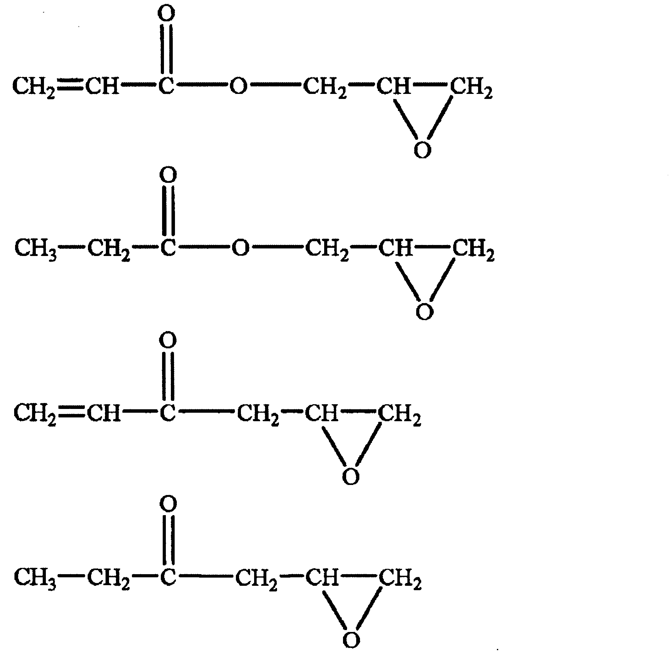
- the epoxy group-containing compound as the affinity improver may be a low molecular weight compound or a high molecular weight compound, and specific examples thereof include an epoxy compound and a glycidyl compound, and preferred examples thereof. Includes a low molecular weight compound having one epoxy group from the viewpoint of affinity with the copolymer.
- R represents a hydrogen atom, a methyl group, a hydrocarbon group having 2 to 10 carbon atoms which may interpose an oxygen atom or a nitrogen atom, or an aromatic ring group which may be substituted.
- R represents a hydrogen atom, a methyl group, a hydrocarbon group having 2 to 10 carbon atoms which may interpose an oxygen atom or a nitrogen atom, or an aromatic ring group which may be substituted.
- m represents 0 or 1
- n represents an integer of 0 to 10.
- Examples of the compound represented by the above formula include a compound having a ketone group or an ester group, and more specifically, a compound represented by the following formula:
- the content of the affinity improver is preferably 0.01 to 30 parts by mass with respect to 100 parts by mass of the inorganic oxide particles, from the viewpoint of uniform dispersion and high relative dielectric constant of the obtained film. , More preferably 0.1 to 25 parts by mass, and even more preferably 1 to 20 parts by mass.
- the piezoelectric film can be a stretched or non-stretched piezoelectric film, and is preferably a non-stretched piezoelectric film.
- the sample film is made of aluminum foil reinforced by attaching an insulating tape to the flat electrode by patterning an aluminum electrode (planar electrode) by vacuum processing vapor deposition on the central portion 5 mm ⁇ 5 mm of the film cut into 20 mm ⁇ 20 mm. It is obtained by adhering the electrodes of two leads (3 mm ⁇ 80 mm) with a conductive double-sided tape.
- This sample film, function generator, high-voltage amplifier, and oscilloscope were installed in a Sawyer tower circuit, a triangular wave was applied to the sample film (up to ⁇ 10 kV), and the response of the sample film was measured using an oscilloscope to obtain an applied electric field of 120 MV. The residual polarization amount at / m is obtained.
- the residual polarization amount of the piezoelectric film is 40 mC / m 2 or more.
- the lower limit of the residual polarization amount is, for example, 45 mC / m 2 , preferably 48 mC / m 2 , more preferably 50 mC / m 2 , and further preferably 52 mC / m 2 from the viewpoint of further improving the piezoelectricity. it can.
- the upper limit of the amount of remanent polarization can be, for example, 80 mC / m 2 , 75 mC / m 2 , or 70 mC / m 2 .
- the remanent polarization amount is, for example, within a range of 48 to 80 mC / m 2 , within a range of 50 to 80 mC / m 2 , within a range of 52 to 80 mC / m 2 , or within a range of 55 to 80 mC / m 2. be able to.
- the “inner haze value” is based on ASTM D1003, and a haze (HAZE, turbidity) using a haze meter NDH7000SP CU2II (product name, Nippon Denshoku Industries Co., Ltd.) or its equivalent. In the test, water is put in a glass cell, the film is inserted therein, and the haze value is measured.
- the internal haze value of the piezoelectric film is preferably more than 30%, more preferably 35% or more, further preferably 40% or more, and more preferably 45% or more. It is even more preferable, it is particularly preferable that it is 50% or more, and it is particularly preferable that it is more than 50%.
- the lower limit of the internal haze value of the piezoelectric film can be preferably 55%, 60%, 65%, or 70% from the viewpoint of further improving the piezoelectricity.
- the upper limit of the internal haze value of the piezoelectric film may be, for example, 80% or 75%.
- the internal haze value of the piezoelectric film is, for example, more than 50% and 80% or less, 55 to 80%, 60 to 80%, 65 to 80%, or 70 to 70%. It can be in the range of 80%.
- the internal haze value [%] / film thickness [ ⁇ m] ratio of the piezoelectric film is preferably more than 1.0, and is 1.1 or more. Is more preferable.
- the ratio of internal haze value [%] / film thickness [ ⁇ m] of the piezoelectric film is usually 2.0 or less, preferably 1.9 or less.
- the ratio of internal haze value [%] / film thickness [ ⁇ m] of the piezoelectric film is, for example, in the range of more than 1.0 and 2.0 or less, or in the range of 1.1 or more and 1.9 or less. be able to.
- the area of the piezoelectric film is preferably 9 cm 2 or more. This range usually corresponds to the range of the area of the film produced by the roll-to-roll method.
- the lower limit of the area of the piezoelectric film is preferably, 10cm 2, 50cm 2, 100cm 2, 200cm 2, 300cm 2, 320cm 2, 400cm 2, 500cm 2, 600cm 2, 700cm 2, 800cm 2, 900cm 2, 1000cm 2 can 1100cm 2, 1200cm 2, 1300cm 2 , 1400cm 2, 1500cm 2, or 1600 cm 2.
- the upper limit of the area of the piezoelectric film may be, for example, 4000 m 2 , 3500 m 2 , 3000 m 2 , 2500 m 2 , 2000 m 2 , 1500 m 2 , 1000 m 2 , or 500 m 2 .
- the area of the piezoelectric film may be, for example, in the range of 10 cm 2 to 4000 m 2 , in the range of 100 cm 2 to 2000 m 2 , or in the range of 600 cm 2 to 500 m 2 .
- the preferred combination of the residual polarization amount, the internal haze value, and the area is as follows.
- the residual polarization amount is 45 mC / m 2 or more, the internal haze value exceeds 30%, and A combination having an area of 9 cm 2 or more
- B The residual polarization amount is 45 mC / m 2 or more, the internal haze value [%] / film thickness [ ⁇ m] ratio exceeds 1.0, and A combination having an area of 9 cm 2 or more
- (C) The residual polarization amount is 45 mC / m 2 or more, the internal haze value exceeds 30%, the internal haze value [%] / film thickness [ ⁇ m] ratio exceeds 1.0, and A combination having an area of 9 cm 2 or more
- D The residual polarization amount is 50 mC / m 2 or more, and the internal haze value is in the range of more than 50% and 80% or less, and A combination having an area of 9
- Crystallinity ⁇ Crystallinity determination method> In the X-ray diffraction pattern obtained when the film sample is directly placed on the sample holder provided with the opening and the X-ray diffraction measurement is performed over the range where the diffraction angle 2 ⁇ is 10 to 40 °, A straight line connecting the diffraction intensity at the diffraction angle 2 ⁇ of 10 ° and the diffraction intensity at the diffraction angle 2 ⁇ of 25 ° is set as a baseline, and the area surrounded by the baseline and the diffraction intensity curve is set by profile fitting to 2 Separated into two symmetrical peaks, Among these, when the larger diffraction angle 2 ⁇ is recognized as the crystalline peak and the smaller diffraction angle 2 ⁇ is recognized as the amorphous halo peak, The value represented by 100 ⁇ (area of crystalline peak) / (sum of area of crystalline peak and area of amorphous halo peak) is defined as crystallinity.
- the lower limit of the crystallinity of the piezoelectric film can be preferably 50% or 55% from the viewpoint of piezoelectricity.
- the lower limit of the crystallinity may be preferably 60%, 65%, or 70% from the viewpoint of dimensional stability by heat and piezoelectricity.
- the upper limit of the crystallinity may be preferably 75%, 70%, 65%, or 60%.
- the crystallinity is, for example, in the range of 50 to 80%, in the range of 55 to 80%, in the range of 60 to 80%, in the range of 65 to 80%, or in the range of 70 to 80%. be able to.
- Piezoelectric constant ⁇ Method for determining piezoelectric constant d 33 The measurement of the piezoelectric constant d 33 is performed by using a piezometer system PM300 (attaching a pin having a tip of 1.5 mm ⁇ as a sample fixing jig) manufactured by PIEZOTEST, or an equivalent product thereof.
- the piezoelectric constant d 33 is measured at 10 points on the selected film excluding the arbitrariness, and the arithmetic average value thereof is defined as the piezoelectric constant d 33 .
- the selection of 10 points while eliminating arbitrariness on the film can be performed, for example, by selecting 10 points at intervals of 50 mm on a straight line.
- the actually measured value of the piezoelectric constant d 33 is a positive value or a negative value depending on the front and back of the film to be measured, but in this specification, the absolute value is described as the value of the piezoelectric constant d 33. .
- the lower limit of the preferable piezoelectric constant d 33 of the piezoelectric film can be, for example, 15 pC / N, 17 pC / N, 18 pC / N, or 19 pC / N.
- the preferable upper limit of the piezoelectric constant d 33 of the piezoelectric film can be, for example, 35 pC / N, 30 pC / N, 28 pC / N, 26 pC / N, or 20 pC / N.
- the piezoelectric constant d 33 of the piezoelectric film is, for example, in the range of 15 to 35 pC / N, in the range of 17 to 35 pC / N, in the range of 18 to 35 pC / N, or in the range of 19 to 35 pC / N. be able to.
- Variation coefficient of the piezoelectric constant d 33 of the variation coefficient piezoelectric film of the piezoelectric constant d 33 is the piezoelectric constant d 33, which is the ratio of the standard deviation to the arithmetic mean.
- the lower limit of the coefficient of variation may be, for example, 0.0001, preferably 0.001, more preferably 0.01, and further preferably 0.02.
- the upper limit of the coefficient of variation is, for example, 2.0, preferably 1.0, more preferably 0.6, still more preferably 0.4, still more preferably 0.3. It can be preferably 0.15.
- the coefficient of variation is, for example, in the range of 0.01 to 1.0, in the range of 0.01 to 0.6, in the range of 0.01 to 0.5, in the range of 0.01 to 0.4. , Or in the range of 0.01 to 0.3.
- the film thickness of the film is the arithmetic mean value of the thicknesses measured at 10 points on the film selected with arbitrariness excluded.
- the lower limit of the film thickness of the piezoelectric film can be, for example, 5 ⁇ m, 9 ⁇ m, or 10 ⁇ m.
- the upper limit of the film thickness of the piezoelectric film may be, for example, 3000 ⁇ m, 2500 ⁇ m, 2000 ⁇ m, 1500 ⁇ m, 1000 ⁇ m, 800 ⁇ m, 500 ⁇ m, 200 ⁇ m, 100 ⁇ m, or 60 ⁇ m.
- the film thickness of the piezoelectric film is, for example, in the range of 5 to 3000 ⁇ m, in the range of 5 to 2500 ⁇ m, in the range of 5 to 2000 ⁇ m, in the range of 5 to 1500 ⁇ m, in the range of 5 to 1000 ⁇ m, and in the range of 5 to 800 ⁇ m. Within the range of 5 to 500 ⁇ m, within the range of 5 to 200 ⁇ m, within the range of 5 to 100 ⁇ m, and within the range of 5 to 60 ⁇ m.
- the preferred film thickness can vary depending on the application of the piezoelectric film.
- Variation coefficient of film thickness ⁇ Method of determining variation coefficient of film thickness>
- the coefficient of variation of the value measured at 10 points every 1 cm square over the entire plane direction of the film is referred to as the coefficient of variation of thickness.
- the coefficient of variation of the thickness of the piezoelectric film can be preferably 10% or less, more preferably 5% or less.
- Retardation ⁇ Method of determining retardation>
- the retardation is measured by cutting out a film sample into a size of 2 cm ⁇ 2 cm or more and using a retardation film / optical material inspection device RETS-100 (product name, Otsuka Electronics) or its equivalent. Is determined by In this specification, a value of 550 nm is adopted as the retardation value.
- the lower limit of the retardation of the piezoelectric film is not particularly limited, but can be, for example, 0.5 nm, 1 nm, 2 nm, 4 nm, 5 nm, or 10 nm.
- the upper limit of the retardation of the piezoelectric film may be, for example, 5000 nm, 4500 nm, 4000 nm, 3500 nm, 3000 nm, 2500 nm, 2000 nm, 1500 nm, 1000 nm, 500 nm, 400 nm, or 300 nm.
- the retardation of the piezoelectric film may be preferably in the range of 0.5 to 500 nm, more preferably in the range of 0.5 to 400 nm, and even more preferably in the range of 1 to 400 nm.
- Ratio of retardation [nm] / film thickness [ ⁇ m] is a value obtained by dividing the retardation determined by the above method by the film thickness determined by the above method.
- the lower limit of the ratio can be, for example, 0.02, 0.05, or 0.1.
- the upper limit of the ratio can be, for example, 2.5, 2.0, or 1.5.
- the ratio can be, for example, in the range of 0.02 to 2.5, or in the range of 0.05 to 2.0.
- the piezoelectric film can be applied to various applications. Specific examples of applications include sensors (eg, touch sensors, vibration sensors, biometric sensors, tire sensors (sensors installed on the inner surface of tires)), actuators, touch panels, haptic devices (devices that provide a tactile feedback to the user), It includes a vibration power generation device (eg, vibration power generation floor, vibration power generation tire), a speaker, and a microphone. Since the piezoelectric film has high dimensional stability due to heat, it can be suitably used for a piezoelectric body including a heat treatment in a manufacturing process among the applications.
- Step A of preparing an unstretched and non-polarized polymer film eg, non-polarized vinylidene fluoride / tetrafluoroethylene copolymer film
- Step A of preparing an unstretched and non-polarized polymer film eg, non-polarized vinylidene fluoride / tetrafluoroethylene copolymer film
- Process A The method for producing the “non-stretched and non-polarized polymer film” by the casting method includes, for example, (1) the vinylidene fluoride / tetrafluoroethylene copolymer, and the desired component (eg, inorganic oxide particles). , And an affinity improver) in a solvent to dissolve or disperse the liquid composition to prepare a liquid composition; (2) applying (casting or coating) the liquid composition onto a substrate; and (3) exposing the substrate to which the liquid composition is applied to a predetermined temperature to form a film. It is a manufacturing method. From the viewpoint of industrial productivity, it is preferable to carry out these steps by a roll-to-roll method.
- the dissolution temperature in the preparation of the liquid composition is not particularly limited, but is preferably room temperature to 80 ° C. from the viewpoint of promoting dissolution and preventing coloration of the film.
- preferred examples of the solvent include ketone solvents (eg, methyl ethyl ketone (MEK), methyl isobutyl ketone (MIBK), acetone, diethyl ketone, dipropyl ketone, cyclohexanone), ester solvents (eg, : Ethyl acetate, methyl acetate, propyl acetate, butyl acetate, ethyl lactate), ether solvents (eg, tetrahydrofuran, methyltetrahydrofuran, dioxane), and amide solvents (eg, dimethylformamide (DMF), dimethylacetamide) .
- amide solvents eg, dimethylformamide (DMF), dimethylacetamide
- the casting (or coating) of the liquid composition onto a substrate is performed by a conventional method (eg, knife coating method, cast coating method, or the like).
- a conventional method eg, knife coating method, cast coating method, or the like.
- Roll coating method, gravure coating method, blade coating method, rod coating method, air doctor coating method, or slot die method are preferable in terms of easy operability, little variation in the obtained film thickness, and excellent productivity.
- the base material for example, a polyethylene terephthalate (PET) film can be used.
- the exposure of the base material to which the liquid composition is applied to a predetermined temperature may be performed according to a usual method of heat treatment (or heat drying) for forming a film.
- the heat treatment (or heat drying) is preferably performed by, for example, a roll-to-roll method by passing the liquid composition applied on the base material through a high-temperature furnace (or a drying furnace). Good.
- the exposure of the substrate to which the liquid composition is applied to a predetermined temperature is performed in two or more stages (for example, within a range of 2 to 4 stages, preferably 2 or 3 stages, more preferably 2 stages). Is preferred.
- the exposing comprises exposing the substrate to a first temperature and exposing the substrate exposed to the first temperature to a second temperature that is lower than the first temperature.
- the step of exposing to the first temperature can be, for example, the step of vaporizing the solvent of the liquid composition.
- the first temperature (or drying temperature) is, for example, in the range of 150 to 230 ° C., preferably in the range of 155 to 220 ° C., more preferably in the range of 160 to 210 ° C., further preferably in the range of 165 to 200 ° C. It is within the range.
- the exposure time (or drying time) to the first temperature is preferably a short time, more preferably less than 1 hour, further preferably 0.8 hours or less (for example, within a range of 0.3 to 0.8 hours). .
- the step of exposing to the second temperature can be, for example, a step of crystallizing or a step of crystal growing (increasing the crystallinity).
- the second temperature is not particularly limited as long as it is lower than the first temperature, and is, for example, in the range of 60 ° C. or higher and lower than 150 ° C., preferably in the range of 80 to 145 ° C., more preferably in the range of 100 to 140 ° C. And more preferably within the range of 110 to 135 ° C.
- the exposure time to the second temperature is preferably a long time, for example, 1 hour or longer, preferably 2 hours or longer, more preferably 3 hours or longer, still more preferably 4 hours or longer, still more preferably 5 hours or longer, and particularly preferably.
- it is exposed to a temperature in the range of 150 to 200 ° C for a short time (eg, less than 1 hour, preferably 0.3 to 0.8 hours), and then exposed to a temperature in the range of 110 ° C to less than 150 ° C for a long time (eg, 5 hours or more) Exposure, preferably 6 hours or more).
- a temperature in the range of 150 to 200 ° C for a short time eg, less than 1 hour, preferably 0.3 to 0.8 hours
- a temperature in the range of 110 ° C to less than 150 ° C for a long time eg, 5 hours or more
- Exposure preferably 6 hours or more
- the thickness of the non-polarized film prepared in step A may be set according to the piezoelectric film to be obtained.
- non-polarized film is preferably unstretched.
- the polarization treatment in step B can be carried out by a conventional method, preferably by corona discharge treatment.
- Either negative corona or positive corona may be used for corona discharge, but it is preferable to use negative corona from the viewpoint of the ease of polarization of the non-polarized film.
- the corona discharge treatment is not particularly limited. For example, as described in JP 2011-181748 A, applying a linear electrode to a non-polarizing film; applying the needle to the non-polarizing film.
- the application can be carried out using electrodes; or the application can be carried out using grid electrodes to the non-polarized film.
- the conditions for the corona discharge treatment may be appropriately set based on common sense in the technical field.
- the piezoelectricity of the obtained piezoelectric film may be insufficient, while if the conditions of the corona discharge treatment are too strong, the obtained piezoelectric film may have point defects. is there.
- the distance between each needle electrode and / or the linear electrode and the film is constant, that is, the electrode and the film.
- There is no in-plane variation in the film distance (or extremely small) (specifically, the difference between the longest distance and the shortest distance is preferably within 6 mm, more preferably within 4 mm, and even more preferably within 3 mm). Yes) is desirable.
- the film when continuous application is performed by roll-to-roll, it is desirable that the film is appropriately and uniformly adhered to the roll by applying a constant tension to the film.
- the DC electric field is, for example, ⁇ 15 although it depends on the distance between the linear electrode and the non-polarized film, the film thickness, and the like. It is within the range of -25 kV.
- the processing speed is, for example, in the range of 10 to 1200 cm / minute.
- the polarization treatment may be performed, for example, by applying it by sandwiching it from both sides of a non-polarizing film with flat plate electrodes, in addition to corona discharge.
- a DC electric field in the range of 0 to 400 MV / m (preferably 50 to 400 MV / m) and 0.1 second
- the application time condition within the range of up to 60 minutes can be adopted.
- Process C heat treatment process
- Step C is performed on Step B at an arbitrary time and if necessary. That is, step C may be performed before step B, at the same time as step B, or after step B.
- the heat treatment in the step C can be performed on the polarized film obtained in the step B or a portion where the polarization is completed in the step B. That is, while performing the polarization treatment of the step B, the heat treatment of the step C may be performed on the portion where the polarization treatment is completed.
- the method of heat treatment is not particularly limited, but, for example, sandwiching the unstretched polymer film (hereinafter sometimes simply referred to as the film) between two metal plates and heating the metal plate; the film Heating the roll in a constant temperature bath; or, in the production of the film in a roll-to-roll system, heating the metal roll and bringing the film into contact with the heated metal roll; or It can be performed by passing it through a heated furnace in a roll-to-roll manner.
- the polarized film may be heat-treated alone, or a laminated film may be formed by laminating it on a film of another kind or a metal foil and then heat-treated. .
- the temperature of the heat treatment may vary depending on the type of the polarized film to be heat treated, and is preferably in the range of (melting point of polarized film to be heat treated ⁇ 100) ° C. to (melting point of polarized film to be heat treated + 40) ° C. It is within. Specifically, the temperature of the heat treatment is preferably in the range of 80 ° C. or higher, more preferably 85 ° C. or higher, even more preferably 90 ° C. or higher. The temperature of the heat treatment is preferably 170 ° C. or lower, more preferably 160 ° C.
- the heat treatment time is usually 10 seconds or longer, preferably 0.5 minutes or longer, more preferably 1 minute or longer, still more preferably 2 minutes or longer. Although the upper limit of the heat treatment time is not limited, the heat treatment time is usually within 60 minutes or less.
- the condition of the heat treatment is preferably 90 ° C. or higher and 1 minute or longer.
- the film is usually cooled to a predetermined temperature.
- the temperature is preferably in the range of 0 ° C. to 60 ° C. and can be room temperature.
- the cooling rate may be slow cooling or rapid cooling, and rapid cooling is preferable from the viewpoint of productivity.
- the rapid cooling can be performed by means such as blowing air.
- the heat treatment of such a film may be referred to as an annealing treatment.
- the piezoelectric film thus obtained has high piezoelectricity even after the annealing treatment and after the production of the piezoelectric body including the heat treatment.
- the piezoelectric film can preferably be stored and shipped as a roll.
- the roll of the piezoelectric film according to an embodiment of the present disclosure may be composed of only the piezoelectric film, or may be a form in which a protective film or the like is laminated on the piezoelectric film and wound, a core such as a paper tube, and the core.
- the piezoelectric film may be wrapped around.
- the roll of the piezoelectric film preferably has a width of 50 mm or more and a length of 20 m or more.
- the roll of the piezoelectric film can be prepared, for example, by winding the piezoelectric film using an unwinding roller and a winding roller.
- the unwinding roller and the winding roller parallel to each other as is usually done.
- the roller in order to improve the slidability of the film, it is preferable to use a roller having good slidability, specifically, a roller coated with a fluororesin, a plated roller, or a roller coated with a release agent.
- both ends are recessed compared to the center; or when the thickness is changed from one end to the other end in an inclined manner, the end on the thin film side is recessed) etc.
- Unevenness of the roll thickness occurs, which may cause wrinkles. Further, this may cause the film to bend (curve in a state where no tension other than the tension due to gravity is applied) when the film is unrolled.
- the edge of the film that is the end of the roll is slittered (slit) .
- slit slit
- the width of the film is wide (for example, width 100 mm or more) as it is or only by slitting the film end that is the end of the roll (slit).
- the length of the film is long (eg, 50 m or more), it is possible to obtain a roll in which the raised edges, the dents and the flexure are suppressed.
- the ears (film end) removed by the slits can be collected and recycled as a raw material of the piezoelectric film.
- the roll of the piezoelectric film has high thickness uniformity, and preferably, the ratio of the thickness of the thicker end portion to the thickness of the central portion in the axial direction of the roll is within the range of 70 to 130%. is there. Thereby, in the roll of the piezoelectric film, the deflection of the film unwound from the roll is suppressed.
- At least the surface material of the roller used for manufacturing the piezoelectric film and the roll thereof is polytetrafluoroethylene (PTFE), chrome plating, or stainless steel (SUS). With these, wrinkles of the film can be suppressed.
- PTFE polytetrafluoroethylene
- SUS stainless steel
- a piezoelectric body is a laminated body, and includes the piezoelectric film and an electrode provided on at least one surface of the piezoelectric film.
- the electrode include an ITO (indium tin oxide) electrode, a tin oxide electrode, metal nanowires, metal nanoparticles (eg, silver nanoparticles), and an organic conductive resin.
- the piezoelectric body includes the piezoelectric film, a positive electrode layer (or an upper electrode layer) provided on one surface of the piezoelectric film, and a negative electrode layer (or a lower electrode) provided on the other surface of the piezoelectric film. It may be a laminated body including layers.
- the piezoelectric body may have an insulating layer on the surface of the electrode layer on which the piezoelectric film is not laminated. Further, the piezoelectric body may have a cover (eg, an electromagnetic shield layer) on a surface (or an outermost surface) of the electrode layer on which the piezoelectric films are not laminated.
- the method for manufacturing the piezoelectric body is, for example, A step of preparing the piezoelectric film; and a step of providing an electrode on at least one surface of the piezoelectric film.
- the method of forming the electrode usually includes heat treatment, and specific examples thereof include a physical vapor deposition method of the electrode material (eg, vacuum deposition, ion plating, sputtering) or It includes a method of forming a film by a chemical vapor deposition method (eg, plasma CVD) and a method of applying an electrode material to a substrate.
- the lower limit of the temperature of the heat treatment is, for example, 25 ° C, preferably 40 ° C, more preferably 50 ° C.
- the upper limit of the temperature of the heat treatment is (melting point of polarized film to be heat treated-3) ° C, for example, 220 ° C, preferably 180 ° C, more preferably 150 ° C, further preferably 130 ° C.
- the temperature of the heat treatment may be, for example, in the range of 25 to 220 ° C, preferably in the range of 40 to 130 ° C. Even if the heat treatment is performed at such a heat treatment temperature, it is possible to remarkably suppress the decrease in piezoelectricity.
- the heat treatment time is usually 10 seconds or longer, preferably 1 minute or longer, more preferably 10 minutes or longer, still more preferably 15 minutes or longer.
- the sample film, the function generator, the high voltage amplifier, and the oscilloscope were incorporated into a Sawyer tower circuit, and a triangular wave was applied to the sample film (up to ⁇ 10 kV).
- a triangular wave was applied to the sample film (up to ⁇ 10 kV).
- the residual polarization amount in an applied electric field of 120 MV / m was obtained.
- NDH7000SP CU2II product name, Nippon Denshoku Industries Co., Ltd.
- ⁇ Crystallinity> The film sample was directly placed on a sample holder provided with an opening, and X-ray diffraction measurement was performed over a range where the diffraction angle 2 ⁇ was 10 to 40 °.
- a straight line connecting the diffraction intensity at the diffraction angle 2 ⁇ of 10 ° and the diffraction intensity at the diffraction angle 2 ⁇ of 25 ° is set as a baseline, and the baseline and the diffraction intensity curve
- the enclosed area was separated into two symmetry peaks by profile fitting. Of these, the larger diffraction angle 2 ⁇ was identified as the crystalline peak, and the smaller diffraction angle 2 ⁇ was identified as the amorphous halo peak. .
- the crystallinity was calculated by 100 ⁇ (area of crystalline peak) / (sum of area of crystalline peak and area of amorphous halo peak).
- Thickness variation coefficient (%) ⁇ [(maximum thickness-average thickness) + (average thickness-minimum thickness)] / average thickness / 2 x 100 ⁇ Piezoelectric constant d 33 > The piezoelectric constant d 33 was measured using a piezometer system PM300 manufactured by PIEZOTEST.
- the retardation was determined by cutting out a film sample into a size of 2 cm ⁇ 2 cm or more and using a retardation film / optical material inspection apparatus RETS-100 (product name, Otsuka Electronics). As the numerical value of retardation, a value of 550 nm was adopted.
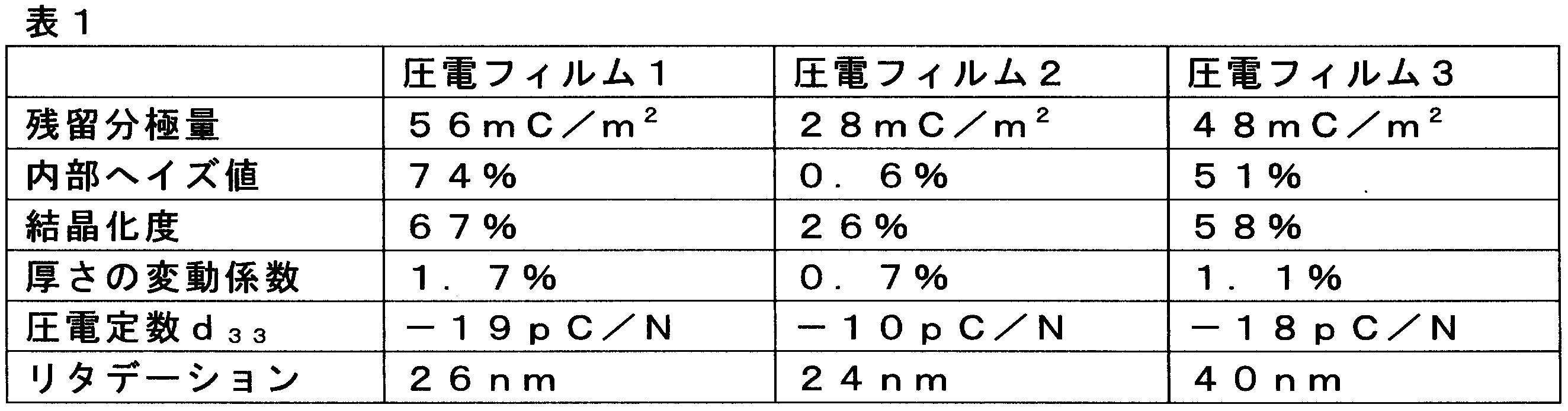
- the piezoelectric film 1 having a film thickness of 40 ⁇ m and an area of 50 m 2 was produced by a roll-to-roll method. Specifically, the piezoelectric film 1 was prepared by casting a methylethylketone solution of vinylidene fluoride / tetrafluoroethylene copolymer 24 wt% (molar ratio 80:20) on a PET base film fed from a roll, After being treated at 0.5 ° C. for 0.5 hour to evaporate the solvent, the temperature was lowered to 120 ° C., the temperature was maintained for 6 hours, then cooled to room temperature, and the polarization treatment described below was performed to obtain it.
- a methylethylketone solution of vinylidene fluoride / tetrafluoroethylene copolymer 24 wt% (molar ratio 80:20) After being treated at 0.5 ° C. for 0.5 hour to evaporate the solvent, the temperature was lowered to 120 ° C., the temperature was maintained for 6
- the piezoelectric film 1 having a film thickness of 40 ⁇ m and an area of 50 m 2 was produced by a roll-to-roll method. Specifically, the piezoelectric film 1 was prepared by casting a methylethylketone solution of vinylidene fluoride / tetrafluoroethylene copolymer 24 wt% (molar ratio 80:20) on a PET base film fed from a roll, It was obtained by subjecting the solvent to vaporization at 0.5 ° C. for 0.5 hour, lowering the temperature to 120 ° C., holding for 1 second, then cooling to room temperature, and performing the polarization treatment described below.
- the piezoelectric film 1 having a film thickness of 40 ⁇ m and an area of 50 m 2 was produced by a roll-to-roll method. Specifically, the piezoelectric film 1 was prepared by casting a methylethylketone solution of vinylidene fluoride / tetrafluoroethylene copolymer 24 wt% (molar ratio 80:20) on a PET base film fed from a roll, It was obtained by subjecting the solvent to vaporization at 0.5 ° C. for 0.5 hours, lowering the temperature to 120 ° C., holding for 5 hours, then cooling to room temperature, and performing the polarization treatment described below.
- Polarization treatment In a clean room of ISO class 7 (humidity 60%), as shown in the outline in Fig. 1, hold it on a grounded roller 1 (diameter 200 mm, width 800 mm) made of SUS, a ground electrode.
- a vinylidene fluoride / tetrafluoroethylene copolymer film 2 (having a width of 550 mm, a length of 200 m, and each film thickness (20 to 40 ⁇ m) shown in Table 1 so as to move along the roller 1 at an angle of 200 ° ( Hereinafter, it may be simply referred to as film 2).
- a needle-shaped electrode is arranged such that the arrangement of the needle-shaped electrodes is perpendicular to the surface of the roller 1 (that is, the radial direction of the roller 1), and the needle-shaped electrode is formed from the film 2 (first electrode).
- the electrode E1) was placed so that the tip thereof was located 10 mm above the sky.
- a first high voltage power supply V1 is connected to the first electrode E1.
- a gold-plated tungsten having a diameter of 0.1 mm was formed as a second electrode E2 at a position separated by 100 mm and a position separated by 150 mm in the length of the film 2 from the needle-shaped electrode (first electrode E1).
- One linear electrode (550 mm long) made of was manufactured so as to be located 20 mm above the film 2 in the sky.
- the second high voltage power supply V2 is connected to each of the second electrodes E2.
- the film 2 was applied at a speed of 96 cm / min.
- the metal roll is moved in the direction of the arrow in FIG. 3 to pass under the corona discharge generated from the tip of the needle electrode (first electrode) and the linear electrode (second electrode) following it, and is further grounded. 3 (70 mm diameter) was contacted and the film 2 was discharged.
- both ends of the film 2 were removed by a width of 0.5 cm using a slitter, and the obtained polarized film was wound around a cylindrical core having a diameter of 6 inches while sandwiching the PET film therebetween.
- a polarized film was prepared.
- both the distance between the needle-shaped electrode (first electrode E1) and the film 2 and the distance between the linear electrode (second electrode E2) and the film 2 are constant (the longest distance and the shortest distance between the electrode and the film). The difference in distance was adjusted to 0 mm).
Landscapes
- Engineering & Computer Science (AREA)
- Physics & Mathematics (AREA)
- Health & Medical Sciences (AREA)
- Manufacturing & Machinery (AREA)
- Acoustics & Sound (AREA)
- Signal Processing (AREA)
- Spectroscopy & Molecular Physics (AREA)
- General Physics & Mathematics (AREA)
- Chemical & Material Sciences (AREA)
- General Engineering & Computer Science (AREA)
- Life Sciences & Earth Sciences (AREA)
- Theoretical Computer Science (AREA)
- Dispersion Chemistry (AREA)
- Physiology (AREA)
- Medical Informatics (AREA)
- Polymers & Plastics (AREA)
- Medicinal Chemistry (AREA)
- Dentistry (AREA)
- Oral & Maxillofacial Surgery (AREA)
- Chemical Kinetics & Catalysis (AREA)
- Biophysics (AREA)
- Pathology (AREA)
- Biomedical Technology (AREA)
- Heart & Thoracic Surgery (AREA)
- Organic Chemistry (AREA)
- Molecular Biology (AREA)
- Surgery (AREA)
- Animal Behavior & Ethology (AREA)
- General Health & Medical Sciences (AREA)
- Public Health (AREA)
- Veterinary Medicine (AREA)
- Human Computer Interaction (AREA)
- Manufacture Of Macromolecular Shaped Articles (AREA)
- Piezo-Electric Transducers For Audible Bands (AREA)
- Particle Formation And Scattering Control In Inkjet Printers (AREA)
Abstract
Description
圧電フィルムとして、典型的には、ポリフッ化ビニリデン(PVDF)フィルムが使用される。PVDFフィルムに良好な圧電性を付与するためには、PVDFフィルムを一軸延伸して分極処理を施すことが必要である(例えば、特許文献1)。
また、圧電フィルムとして、フッ化ビニリデン/テトラフルオロエチレン共重合体フィルムを使用することも提案されている(例えば、特許文献2)。
また、フッ化ビニリデン/テトラフルオロエチレン共重合体フィルムは、PVDFフィルムよりも圧電性が低いため、圧電性について更なる改善が求められる。
本開示は、良好な圧電性を有する圧電フィルムを提供することを目的とする。
項1.
フッ化ビニリデン/テトラフルオロエチレン共重合体フィルムからなり、
残留分極量が40mC/m2以上である、圧電フィルム。
項2.
残留分極量が45mC/m2以上である、項1に記載の圧電フィルム。
項3.
内部ヘイズ値[%]/膜厚[μm]の比が1.0を超える、項1又は2に記載の圧電フィルム。
項4.
内部ヘイズ値[%]/膜厚[μm]の比が1.1以上である、項1~3のいずれか一項に記載の圧電フィルム。
項5.
内部ヘイズ値が30%を超える、項1~4のいずれか一項に記載の圧電フィルム。
項6.
内部ヘイズ値が40%以上である、項1~5のいずれか一項に記載の圧電フィルム。
項7.
内部ヘイズ値が45%以上である、項1~6のいずれか一項に記載の圧電フィルム。
項8.
面積が9cm2以上である、項1~7のいずれか一項に記載の圧電フィルム。
項9.
残留分極量が50mC/m2以上であり、且つ
内部へイズ値が50%を超えて80%以下の範囲内であり、且つ、
面積が9cm2以上である、項1~8のいずれか一項に記載の圧電フィルム。
項10.
開口部が設けられたサンプルホルダにフィルム試料を直接載置し、回折角2θが10~40°である範囲にわたってX線回折測定を行ったときに得られるX線回折パターンにおいて、
10°の回折角2θにおける回折強度と、25°の回折角2θにおける回折強度とを結ぶ直線をベースラインとして設定し、及び
当該ベースラインと回折強度曲線とで囲まれる領域を、プロファイルフィッティングにより2つの対称性ピークに分離し、
このうち、回折角2θの大きい方を結晶性ピークと認定し、且つ回折角2θの小さい方を非晶性ハローピークと認定した場合に、
100×(結晶性ピークの面積)/(結晶性ピークの面積と非晶性ハローピークの面積との和)で表される結晶化度が、50%以上である、項1~9のいずれか一項に記載の圧電フィルム。
項11.
結晶化度が55%以上である、項10に記載の圧電フィルム。
項12.
平面方向の全体に渡って1cm四方毎に10箇所において厚さを測定したときの厚さの変動係数が10%以下である、項1~11のいずれか一項に記載の圧電フィルム。
項13.
圧電定数d33が15pC/N以上である、項1~12のいずれか一項に記載の圧電フィルム。
項14.
厚さが、5~3000μmである、項1~13のいずれか一項に記載の圧電フィルム。項15.
内部ヘイズ値が60~80%の範囲内である、項1~14のいずれか一項に記載の圧電フィルム。
項16.
内部ヘイズ値が65~80%の範囲内である、項1~15のいずれか一項に記載の圧電フィルム。
項17.
前記フッ化ビニリデン/テトラフルオロエチレン共重合体において、フッ化ビニリデンに由来する繰り返し単位とテトラフルオロエチレンに由来する繰り返し単位とのモル比が、60/40~97/3の範囲内である、項1~16のいずれか一項に記載の圧電フィルム。
項18.
リタデーション[nm]/膜厚[μm]の比が0.02~2.5の範囲内である、項1~17のいずれか一項に記載の圧電フィルム。
項19.
センサ、アクチュエータ、タッチパネル、ハプティックデバイス、振動発電装置、スピーカー、及びマイクからなる群より選択される1種以上に使用するための、項1~18のいずれか一項に記載の圧電フィルム。
項20.
積層体であり、
項1~18のいずれか一項に記載の圧電フィルム、及び
前記圧電フィルムの少なくとも一方の面上に設けられた電極を備える圧電体。
・圧電フィルムの製造方法であって、
(1)フッ化ビニリデン/テトラフルオロエチレン共重合体及び溶媒を含む液状組成物を調製する工程;
(2)前記液状組成物を基材上に適用する工程;及び
(3)前記液状組成物を適用した基材を所定の温度に暴露してフィルムを形成させる工程を含む製造方法。
・工程(3)が、前記基材を150~200℃の範囲内で1時間未満暴露し、次いで110℃以上150℃未満の範囲内で5時間以上暴露する工程である、前記製造方法。
本開示の後記説明は、実例の実施形態をより具体的に例示する。
本開示のいくつかの箇所では、例示を通してガイダンスが提供され、及びこの例示は、様々な組み合わせにおいて使用できる。
それぞれの場合において、例示の群は、非排他的な、及び代表的な群として機能できる。
本明細書で引用した全ての刊行物、特許及び特許出願はそのまま引用により本明細書に組み入れられる。
本明細書中の記号及び略号は、特に限定のない限り、本明細書の文脈に沿い、本開示が属する技術分野において通常用いられる意味に理解できる。
本明細書中、語句「含有する」は、語句「から本質的になる」、及び語句「からなる」を包含することを意図して用いられる。
特に限定されない限り、本明細書中に記載されている工程、処理、又は操作は、室温で実施され得る。
本明細書中、室温は、10~40℃の範囲内の温度を意味することができる。
本明細書中、表記「Cn-m」(ここで、n、及びmは、それぞれ、数である。)は、当業者が通常理解する通り、炭素数がn以上、且つm以下であることを表す。
本開示の一実施形態の圧電フィルムは、フッ化ビニリデン/テトラフルオロエチレン共重合体フィルムからなる。
前記フッ化ビニリデン/テトラフルオロエチレン共重合体において、フッ化ビニリデンに由来する繰り返し単位(-CH2-CF2-)及びテトラフルオロエチレンに由来する繰り返し単位(-CF2-CF2-)のモル比は、限定されるものではないが、例えば50/50~99/1の範囲内であることができる。前記モル比は、熱による寸法安定性を向上する点から、60/40~97/3の範囲内が好ましく、65/35~95/5の範囲内がより好ましく、70/30~90/10の範囲内が特に好ましい。
フッ化ビニリデン及び/又はテトラフルオロエチレンからなる共重合であってもよく、フッ化ビニリデン及び/又はテトラフルオロエチレンから本質的になる共重合であってもよい。
前記フッ化ビニリデン/テトラフルオロエチレン共重合体は、また、フッ化ビニリデン及び/又はテトラフルオロエチレンと共重合可能なコモノマーを含んでいてもよい。当該コモノマーは、エチレン性不飽和二重結合を有していてもよい。
当該コモノマーの具体例は、
フッ素含有モノマー[例:ビニルフルオリド(VF)、トリフルオロエチレン(TrFE)、ヘキサフルオロプロペン(HFP)、1-クロロ-1-フルオロエチレン(1,1-CFE)、1-クロロ-2-フルオロエチレン(1,2-CFE)、1-クロロ-2,2-ジフルオロエチレン(CDFE)、クロロトリフルオロエチレン(CTFE)、トリフルオロビニルモノマー、1,1,2-トリフルオロブテン-4-ブロモ-1-ブテン、1,1,2-トリフルオロブテン-4-シラン-1-ブテン、ペルフルオロプロピルビニルエーテル(PPVE)、ペルフルオロアクリラート、2,2,2-トリフルオロエチルアクリラート、2-(ペルフルオロヘキシル)エチルアクリラート)]、
フッ素非含有モノマー[例:α-オレフィン(例:エチレン、プロピレン);不飽和ジカルボン酸、又はその誘導体(例:マレイン酸、無水マレイン酸);ビニルエーテル(例:エチルビニルエーテル);アリルエーテル(例:アリルグリシジルエーテル);ビニルエステル(例:酢酸ビニル);アクリル酸、又はそのエステル;メタクリル酸、又はそのエステル]、及び
これら1種又は2種以上の組合せ
を包含する。
前記フッ化ビニリデン/テトラフルオロエチレン共重合体は、前記コモノマーに由来する繰り返し単位を、全モノマーに由来する繰り返し単位中、例えば10モル%以下、好ましくは0.01~5モル%の範囲内で含有することができる。
前記金属元素の例は、Be、Mg、Ca、Sr、Ba、Y、Ti、Zr、Zn、及びAlを包含する。
(B1)の好適な例は、Be、Al、Mg、Y、及びZrの酸化物の粒子を包含する。前記粒子は、汎用で安価であり、また体積抵抗率が高い点から好ましい。
(B1)の更に好適な例は、Al2O3、MgO、ZrO2、Y2O3、BeO、及びMgO・Al2O3からなる群より選ばれる少なくとも1種の無機酸化物の粒子を包含する。前記粒子は、体積抵抗率が高い点から好ましい。
(B1)の更に好適な例は、結晶構造がγ型のAl2O3を包含する。前記粒子は、比表面積が大きく、フッ化ビニリデン/テトラフルオロエチレン共重合体への分散性が良好な点から好ましい。
前記2族金属元素の好適な例は、Mg、Ca、Sr、及びBaを包含する。
前記4族金属元素の好適な例は、Ti、及びZrを包含する。
(B2)の好適な例は、BaTiO3、SrTiO3、CaTiO3、MgTiO3、BaZrO3、SrZrO3、CaZrO3、及びMgZrO3からなる群より選ばれる少なくとも1種の無機酸化物の粒子を包含する。前記粒子は、体積抵抗率が高い点から好ましい。
前記金属元素の例は、Be、Mg、Ca、Sr、Ba、Y、Ti、Zr、Zn、及びAlを包含する。
(B3)の具体例は、3A12O3・2SiO2、2MgO・SiO2、ZrO2・SiO2、及びMgO・SiO2からなる群より選ばれる少なくとも1種の無機酸化物の粒子を包含する。
前記無機酸化物粒子の比誘電率(ε)(25℃、1kHz)は、LCRメーターを用いて容量(C)を測定し、容量、電極面積(S)、焼結体の厚さ(d)から、式C=εε0×S/d(ε0:真空の誘電率)で算出した値である。
前記無機酸化物粒子の平均一次粒子径は、レーザー回折・散乱式粒度分布測定装置 LA-920(商品名)(堀場製作所社)又はその同等品を用いて算出される。
前記含有量の下限は、電気絶縁性を向上する点から、好ましくは0.1質量部、より好ましくは0.5質量部、更に好ましくは1質量部である。
前記含有量の上限は、前記無機酸化物粒子を前記共重合体中に均一に分散させ、電気絶縁性(耐電圧)の低下、及びフィルムの引張強度の低下を防止する点から、好ましくは200質量、より好ましくは150質量部、更に好ましくは100質量部である。
前記圧電フィルムに、高い全光透過率、及び低い全ヘイズ値が要求される場合、前記含有量は、小さい方が好ましく、ゼロであることがより好ましい。
前記親和性向上剤は、前記無機酸化物粒子と前記共重合体との間の親和性を高め、前記無機酸化物粒子を前記共重合体中に均一に分散させ、前記無機酸化物粒子と前記共重合体をフィルム中でしっかり結合させ、ボイドの発生を抑制し、及び比誘電率を高めることができる。
前記有機チタン化合物の好適な例は、無機酸化物粒子との親和性が良好な点から、アルコキシチタニウム、及びチタニウムキレートを包含する。
前記界面活性剤の例は、非イオン性界面活性剤、アニオン性界面活性剤、及びカチオン性界面活性剤を包含する。

で表される化合物を包含する。
<残留分極量の決定方法>
試料フィルムは、20mm×20mmに切り出したフィルムの中央部5mm×5mmに、アルミニウム電極(平面電極)を真空加工蒸着によりパターニングし、この平面電極に、絶縁テープを貼り付けて補強したアルミニウム箔製の2本のリード(3mm×80mm)の電極を導電性両面テープで接着することにより得られる。この試料フィルム、ファンクションジェネレーター、高圧アンプ、及びオシロスコープをソーヤータワー回路に組み込み、三角波を試料フィルムに印加(最大±10kV)し、試料フィルムの応答を、オシロスコープを用いて測定することにより、印加電界120MV/mにおける残留分極量が得られる。
前記残留分極量の下限は、更なる圧電性の向上の点から、例えば45mC/m2、好ましくは48mC/m2、より好ましくは50mC/m2、更に好ましくは52mC/m2であることができる。
前記残留分極量の上限は、例えば、80mC/m2、75mC/m2、又は70mC/m2であることができる。
前記残留分極量は、例えば、48~80mC/m2の範囲内、50~80mC/m2の範囲内、52~80mC/m2の範囲内、又は55~80mC/m2の範囲内であることができる。
<内部へイズ値の決定方法>
本明細書において、「内部ヘイズ値」(inner haze)は、ASTM D1003に準拠し、ヘイズメーター NDH7000SP CU2II(製品名、日本電色工業社)又はその同等品を使用したヘイズ(HAZE、濁度)試験において、ガラス製セルの中に水を入れて、その中にフィルムを挿入し、ヘイズ値を測定することにより得られる。
前記圧電フィルムの内部ヘイズ値の下限は、更なる圧電性の向上の点から、好ましくは55%、60%、65%、又は70%であることができる。
前記圧電フィルムの内部ヘイズ値の上限は、例えば、80%、又は75%であることができる。
前記圧電フィルムの内部ヘイズ値は、例えば、50%を超えて80%以下の範囲内、55~80%の範囲内、60~80%の範囲内、65~80%の範囲内、又は70~80%の範囲内であることができる。
前記圧電フィルムの内部ヘイズ値[%]/膜厚[μm]の比は、1.0を超えるのが好ましく、1.1以上であるのがより好ましい。
また、前記圧電フィルムの内部ヘイズ値[%]/膜厚[μm]の比は、通常、2.0以下であり、1.9以下が好ましい。
前記圧電フィルムの内部ヘイズ値[%]/膜厚[μm]の比は、例えば、1.0を超えて2.0以下の範囲内、又は1.1以上1.9以下の範囲内であることができる。
前記圧電フィルムの面積は、工業生産性の点から、9cm2以上の範囲内であるのが好ましい。この範囲は、通常、ロール・トゥ・ロール方式で製造されるフィルムの面積の範囲に対応する。
前記圧電フィルムの面積の下限は、好ましくは、10cm2、50cm2、100cm2、200cm2、300cm2、320cm2、400cm2、500cm2、600cm2、700cm2、800cm2、900cm2、1000cm2、1100cm2、1200cm2、1300cm2、1400cm2、1500cm2、又は1600cm2であることができる。
前記圧電フィルムの面積の上限は、例えば、4000m2、3500m2、3000m2、2500m2、2000m2、1500m2、1000m2、又は500m2であることができる。
前記圧電フィルムの面積は、例えば、10cm2~4000m2の範囲内、100cm2~2000m2の範囲内、又は600cm2~500m2の範囲内であることができる。
(a)残留分極量が45mC/m2以上であり、且つ
内部へイズ値が30%を超え、且つ、
面積が9cm2以上である組合せ、
(b)残留分極量が45mC/m2以上であり、且つ
内部ヘイズ値[%]/膜厚[μm]の比が1.0を超え、且つ、
面積が9cm2以上である組合せ、
(c)残留分極量が45mC/m2以上であり、且つ
内部ヘイズ値が30%を超え、且つ
内部ヘイズ値[%]/膜厚[μm]の比が1.0を超え、且つ、
面積が9cm2以上である組合せ、
(d)残留分極量が50mC/m2以上であり、且つ
内部へイズ値が50%を超えて80%以下の範囲内であり、且つ、
面積が9cm2以上である組合せ。
<結晶化度の決定方法>
開口部が設けられたサンプルホルダにフィルム試料を直接載置し、回折角2θが10~40°である範囲にわたってX線回折測定を行ったときに得られるX線回折パターンにおいて、
10°の回折角2θにおける回折強度と、25°の回折角2θにおける回折強度とを結ぶ直線をベースラインとして設定し、及び
当該ベースラインと回折強度曲線とで囲まれる領域を、プロファイルフィッティングにより2つの対称性ピークに分離し、
このうち、回折角2θの大きい方を結晶性ピークと認定し、且つ回折角2θの小さい方を非晶性ハローピークと認定した場合に、
100×(結晶性ピークの面積)/(結晶性ピークの面積と非晶性ハローピークの面積との和)で表される値を結晶化度とする。
前記結晶化度の下限は、熱による寸法安定性及び圧電性の点から、好ましくは60%、65%、又は70%であることができる。
前記結晶化度の上限は、好ましくは75%、70%、65%、又は60%であることができる。
前記結晶化度は、例えば、50~80%の範囲内、55~80%の範囲内、60~80%の範囲内、65~80%の範囲内、又は70~80%の範囲内であることができる。
<圧電定数d33の決定方法>
圧電定数d33の測定は、PIEZOTEST社のピエゾメーターシステムPM300(サンプル固定治具として、先端が1.5mmφのピンをとりつける)を用いるか、又はその同等品を用いて行われる。ここで、恣意性を排除して選択したフィルム上の10点において圧電定数d33を測定し、その算術平均値を圧電定数d33とする。フィルム上で恣意性を排除して10点を選択することは、例えば、直線上で50mm間隔に10点を選択することにより行うことができる。ここで、恣意性とは、後記する変動係数が小さくなるように意図することを意味する。
圧電定数d33の実測値は、測定されるフィルムの表裏によって、プラスの値、又はマイナスの値となるが、本明細書中においては、圧電定数d33の値として、その絶対値を記載する。
前記圧電フィルムの好ましい圧電定数d33の上限は、例えば、35pC/N、30pC/N、28pC/N、26pC/N、又は20pC/Nであることができる。
前記圧電フィルムの圧電定数d33は、例えば、15~35pC/Nの範囲内、17~35pC/Nの範囲内、18~35pC/Nの範囲内、又は19~35pC/Nの範囲内であることができる。
圧電フィルムの圧電定数d33の変動係数は、圧電定数d33の、算術平均に対する標準偏差の比である。
前記変動係数の上限は、面内均一性の点から、例えば、2.0、好ましくは1.0、より好ましくは0.6、更に好ましくは0.4、より更に好ましくは0.3、特に好ましくは0.15であることができる。
前記変動係数は、例えば、0.01~1.0の範囲内、0.01~0.6の範囲内、0.01~0.5の範囲内、0.01~0.4の範囲内、又は0.01~0.3の範囲内であることができる。
<膜厚の決定方法>
本明細書中、恣意性を排除して選択したフィルム上の10点で測定した各厚さの算術平均値を、フィルムの膜厚とする。
前記圧電フィルムの膜厚の上限は、例えば、3000μm、2500μm、2000μm、1500μm、1000μm、800μm、500μm、200μm、100μm、又は60μmであることができる。
前記圧電フィルムの膜厚は、例えば、5~3000μmの範囲内、5~2500μmの範囲内、5~2000μmの範囲内、5~1500μmの範囲内、5~1000μmの範囲内、5~800μmの範囲内、5~500μmの範囲内、5~200μmの範囲内、5~100μmの範囲内、5~60μmの範囲内であることができる。好ましい膜厚は、前記圧電フィルムの用途によって異なることができる。
<膜厚の変動係数の決定方法>
本明細書中、フィルムの平面方向の全体に渡って1cm四方毎に10箇所において測定した値の変動係数を、厚さの変動係数とする。
<リタデーションの決定方法>
本明細書中、リタデーションは、フィルムのサンプルを2cm×2cm以上の大きさに切り出して、位相差フィルム・光学材料検査装置RETS-100(製品名、大塚電子)、又はその同等品を用いた測定によって、決定される。本明細書において、リタデーションの数値としては、550nmの値を採用する。
前記圧電フィルムのリタデーションの上限は、例えば、5000nm、4500nm、4000nm、3500nm、3000nm、2500nm、2000nm、1500nm、1000nm、500nm、400nm、又は300nmであることができる。
前記圧電フィルムのリタデーションは、好ましくは0.5~500nmの範囲内、より好ましくは0.5~400nmの範囲内、及び更に好ましくは1~400nmの範囲内であることができる。
リタデーション[nm]/膜厚[μm]の比は、前記方法により決定されたリタデーションを、前記方法により決定された膜厚で除算した値である。
前記比の下限は、例えば、0.02、0.05、又は0.1であることができる。
前記比の上限は、例えば、2.5、2.0、又は1.5であることができる。
前記比は、例えば、0.02~2.5の範囲内、又は0.05~2.0の範囲内であることができる。
前記圧電フィルムは、各種用途に適用することができる。用途の具体例は、センサ(例:タッチセンサ、振動センサ、生体センサ、タイヤセンサ(タイヤ内面に設置するセンサ))、アクチュエータ、タッチパネル、ハプティックデバイス(ユーザに触覚をフィードバックする機能を有するデバイス)、振動発電装置(例:振動発電床、振動発電タイヤ)、スピーカー、及びマイクを包含する。前記圧電フィルムは、熱による寸法安定性が高いため、前記用途の中でも、製造工程が熱処理を含む圧電体に好適に使用することができる。
本開示の一実施態様の圧電フィルムは、例えば、
キャスティング法により無延伸かつ非分極の重合体フィルム(例、非分極のフッ化ビニリデン/テトラフルオロエチレン共重合体フィルム)を調製する工程A;
前記無延伸かつ非分極の重合体フィルムを分極処理する工程B;及び
必要に応じて、工程Bに対して任意の時点で、無延伸の重合体フィルムを熱処理する工程C
を含む製造方法
によって製造できる。
キャスティング法による、「前記無延伸かつ非分極の重合体フィルム」の製造方法は、例えば、(1)前記フッ化ビニリデン/テトラフルオロエチレン共重合体、並びに前記所望による成分(例:無機酸化物粒子、及び親和性向上剤)を溶媒中に溶解又は分散させて液状組成物を溶解させて、液状組成物を調製する工程;
(2)前記液状組成物を基材上に適用(流延又は塗布)する工程;及び
(3)前記液状組成物を適用した基材を所定の温度に暴露してフィルムを形成させる工程を含む製造方法である。これらの工程は、工業生産性の点から、ロール・トゥ・ロール方式で実施するのが好ましい。
着色を防止する点から、前記溶媒の好適な例は、ケトン系溶媒(例:メチルエチルケトン(MEK)、メチルイソブチルケトン(MIBK)、アセトン、ジエチルケトン、ジプロピルケトン、シクロヘキサノン)、エステル系溶媒(例:酢酸エチル、酢酸メチル、酢酸プロピル、酢酸ブチル、乳酸エチル)、エーテル系溶媒(例:テトラヒドロフラン、メチルテトラヒドロフラン、ジオキサン)、及びアミド系溶媒(例:ジメチルホルムアミド(DMF)、ジメチルアセトアミド)を包含する。これらの溶媒は、単独で、又は2種以上を組み合わせて用いられ得る。なお、前記溶媒中のアミド系溶媒の含有率は50質量%以下であることが望ましい。
なかでも、操作性が容易な点、得られるフィルム厚さのバラツキが少ない点、生産性に優れる点から、グラビアコーティング方式、又はスロットダイ方式が好ましい。
前記基材としては、例えば、ポリエチレンテレフタレート(PET)フィルムを用いることができる。
前記液状組成物を適用した基材の所定の温度への暴露は、2段階以上(例えば2~4段階の範囲内、好ましくは2又は3段階、より好ましくは2段階)に分けて実施することが好ましい。
前記暴露は、前記基材を第1の温度に暴露する段階、及び前記第1の温度に暴露した基材を、第1の温度よりも低い第2の温度に暴露する段階を含むことが好ましい。
第1の温度に暴露する段階は、例えば、液状組成物の溶媒を気化させる段階であることができる。第1の温度(又は乾燥温度)は、例えば、150~230℃の範囲内、好ましくは155~220℃の範囲内、より好ましくは160~210℃の範囲内、さらに好ましくは165~200℃の範囲内である。第1の温度に暴露する時間(又は乾燥時間)は、短時間が好ましく、1時間未満がより好ましく、0.8時間以下(例えば、0.3~0.8時間の範囲内)がさらに好ましい。
第2の温度に暴露する段階は、例えば、結晶化させる段階、結晶成長させる(結晶化度を上昇させる)段階であることができる。第2の温度は、第1の温度よりも低ければ特に制限されず、例えば、60℃以上150℃未満の範囲内、好ましくは80~145℃の範囲内、より好ましくは100~140℃の範囲内、さらに好ましくは110~135℃の範囲内である。第2の温度に暴露する時間は、長時間が好ましく、例えば1時間以上、好ましくは2時間以上、より好ましくは3時間以上、さらに好ましくは4時間以上、さらにより好ましくは5時間以上、特に好ましくは6時間以上である。
特に、150~200℃の範囲内で短時間(例えば1時間未満、好ましくは0.3~0.8時間)暴露し、次いで110℃以上150℃未満の範囲内で長時間(例えば5時間以上、好ましくは6時間以上)暴露することが好ましい。このような処理により、残留分極量が大きいだけでなく、内部へイズ値、結晶化度等の他の物性も満足し得る圧電フィルムを形成することができる。
工程Bに用いられる、非分極の前記共重合体フィルム(以下、単に「非分極フィルム」と称する場合がある)は、好ましくは、延伸されていないものである。
コロナ放電には、負コロナ及び正コロナのいずれを用いてもよいが、非分極フィルムの分極しやすさの観点から負コロナを用いることが望ましい。
コロナ放電処理は、特に限定されないが、例えば、特開2011-181748号公報に記載のように非分極フィルムに対して線状電極を用いて印加を実施すること;非分極フィルムに対して針状電極を用いて印加を実施すること;又は非分極フィルムに対してグリッド電極を用いて印加を実施すること、によって実施できる。
コロナ放電処理の条件は、当該技術分野の常識に基づいて、適宜設定すればよい。コロナ放電処理の条件が弱すぎると、得られる圧電フィルムの圧電性が不充分になる虞があり、一方、コロナ放電処理の条件が強すぎると、得られる圧電フィルムが点状欠陥を有する虞がある。
ここで、得られる分極フィルムの圧電定数d33の面内ばらつきを抑制するためには、各針状電極、及び/又は線状電極とフィルムとの距離が一定であること、すなわち電極とフィルムとの間の距離にフィルム面内ばらつきが無いこと(又は極めて小さいこと)(具体的には、最長距離と最短距離の差が、好ましくは、6mm以内、より好ましくは4mm、更に好ましくは3mm以内であること)が望ましい。
また、例えば、ロール・トゥ・ロールで連続印加を実施する場合は、フィルムに一定の張力がかかるようにして、フィルムを適度且つ均一にロールに密着させることが、望ましい。
例えば、線状電極を用いてロール・トゥ・ロールで連続印加を実施する場合は、線状電極と非分極フィルムの間の距離、フィルム膜厚等によって異なるが、直流電界は、例えば、-15~-25kVの範囲内である。処理速度は、例えば、10~1200cm/分の範囲内である。
別法として、分極処理は、コロナ放電の他に、例えば非分極フィルムの両面から平板電極で挟み込んで印加することにより実施してもよい。具体的には、例えば、非分極フィルムの両面から平板電極で挟み込んで印加を実施する場合、0~400MV/m(好ましくは50~400MV/m)の範囲内の直流電界、及び0.1秒~60分間の範囲内の印加時間の条件を採用できる。
工程Cは、工程Bに対して任意の時点で、必要に応じて行われる。すなわち、工程Cは、工程Bの前、工程Bと同時、又は工程Bの後に実施してもよい。工程Cを工程Bの後に行う場合、工程Cの熱処理は、工程Bで得られた分極化フィルム又は工程Bにおいて分極を完了した部分に対して行うことができる。すなわち、工程Bの分極処理を実施しながら、当該分極処理を終えた部分に対して工程Cの熱処理を実施してもよい。
熱処理の方法は、特に限定されないが、例えば、前記無延伸の重合体フィルム(以下、単に前記フィルムと称する場合がある)を2枚の金属板で挟み、当該金属板を加熱すること;前記フィルムのロールを恒温槽中で加熱すること;又はロール・トゥ・ロール方式での前記フィルムの生産において、金属ロールを加熱し、前記フィルムを、当該加熱した金属ロールに接触させること;又は前記フィルムを加熱した炉の中にロール・トゥ・ロールで通していくことにより行うことができる。ここで、工程Cを工程Bの後に行う場合、分極化フィルムは単体で熱処理してもよいし、或いは別種のフィルム又は金属箔上に重ねて積層フィルムを作成し、これを熱処理してもよい。とりわけ、高温で熱処理する場合には後者の方法のほうが、分極化フィルムにしわが入りにくいので好ましい。
前記熱処理の温度は、熱処理される分極化フィルムの種類によって異なる場合があり、好ましくは(熱処理される分極化フィルムの融点-100)℃~(熱処理される分極化フィルムの融点+40)℃の範囲内である。
前記熱処理の温度は、具体的には、好ましくは80℃以上、より好ましくは85℃以上、更に好ましくは90℃以上の範囲内である。
また、前記熱処理の温度は、好ましくは170℃以下、より好ましくは160℃以下、更に好ましくは140℃以下の範囲内である。
前記熱処理の時間は、通常、10秒間以上、好ましくは0.5分間以上、より好ましくは1分間以上、更に好ましくは2分間以上の範囲内である。
また、前記熱処理の時間の上限は限定されないが、通常、前記熱処理の時間は60分間以下の範囲内である。
前記熱処理の条件は、好ましくは90℃以上で1分間以上の範囲内である。
このようにして得られる圧電フィルムは、アニール処理後でも、さらに製造工程が熱処理を含む圧電体を製造した後でも、高い圧電性を有する。
前記圧電フィルムは、好ましくは、ロールとして保管及び出荷され得る。
本開示の一実施態様の圧電フィルムのロールは、前記圧電フィルムのみからなってもよく、前記圧電フィルムに保護フィルムなどを積層させて巻いた形態でもよく、紙管等の芯、及び当該芯に巻き付けられた前記圧電フィルムを備えてもよい。
前記圧電フィルムのロールは、好ましくは、幅50mm以上の範囲内、かつ長さ20m以上の範囲内である。
前記圧電フィルムのロールは、例えば、前記圧電フィルムを、巻き出しローラーと巻き取りローラーを用いて巻き取ることにより、調製できる。
ここで、フィルムのたわみを抑制する観点で、通常行われるように、巻き出しローラーと巻き取りローラーを平行にすることが好ましい。
ローラーとしては、フィルムの滑り性を良くするため、滑り性のよいローラー、具体的にはフッ素樹脂で被覆されたローラー、メッキされたローラー、又は離型剤を塗布したローラーを用いることが好ましい。
ここで、フィルムの厚さが不均一である場合は、いわゆるロールの耳立ち(ハイエッジ;ロールの軸方向の中心部に比べて、端部が太くなること;両端部が中心部より膜厚が低い場合に両端部が中心部に比べて凹むこと;又は一方の端部からもう一方の端部に傾斜的に厚さが変化していく場合に膜厚が薄い側の端部が凹むこと)等のロールの太さの不均一さが発生し、これはシワの発生の原因になり得る。また、これは、フィルムの捲き出しの際に、フィルムのたわみ(重力による張力以外の張力がかけられていない状態での湾曲)が発生する原因となり得る。
一般に、ロールの耳立ちを防止する目的で、ロールの端となるフィルム端をスリッター耳おとし(スリット)することが行われるが、フィルムの厚さの不均一がフィルム端から広い範囲にわたる場合、耳おとしのみでは、ロールの耳立ち及び凹みの防止が困難である。
また、一般に、フィルムの幅が広い(例:幅100mm以上)ほど、及びフィルムの長さが長い(例:50m以上)ほど、前記耳立ち、前記凹み及び前記たわみが生じやすい。 しかし、前記圧電フィルムは、厚さの均一性が高いので、そのまま、又はロールの端となるフィルム端をスリッター耳おとし(スリット)することのみで、フィルムの幅が広く(例:幅100mm以上)、かつフィルムの長さが長い(例:50m以上)場合でも、前記耳立ち、前記凹み及び前記たわみが抑制されたロールにすることができる。
スリットで除去された耳(フィルム端)は、回収して、前記圧電フィルムの原料として、リサイクルできる。
前記圧電フィルムのロールは、太さの均一性が高く、好ましくは、ロールの軸方向の中心部の太さに対する、より太いほうの端部の太さの比が70~130%の範囲内である。これにより、前記圧電フィルムのロールは、これから巻き出されたフィルムのたわみが抑制されている。
また、前記圧電フィルム及びそのロールの製造に用いられるローラーは、少なくともその表面の材質が、ポリテトラフルオロエチレン(PTFE)、クロムメッキ、又はステンレス鋼(SUS)であることが好ましい。
これらのことにより、フィルムのシワを抑制できる。
本開示の一実施態様の圧電体は、積層体であり、前記圧電フィルム、及び、前記圧電フィルムの少なくとも一方の面上に設けられた電極を備える。
前記電極の具合例は、ITO(酸化インジウム・スズ)電極、酸化スズ電極、金属ナノワイヤー、金属ナノ粒子(例:銀ナノ粒子)、及び有機導電樹脂を含む。
前記圧電体は、前記圧電フィルム、前記圧電フィルムの一方の面上に設けられた正電極層(又は上部電極層)、及び前記圧電フィルムの他方の面に設けられた負電極層(又は下部電極層)を備えた積層体であってもよい。
前記圧電体は、電極層の圧電フィルムが積層されていない面に、絶縁層を有していてもよい。また、前記圧電体は、電極層の圧電フィルムが積層されていない面(又は最表面)にカバー(例:電磁シールド層)を有していてもよい。
圧電体の製造方法は、例えば、
前記圧電フィルムを準備する工程;及び
前記圧電フィルムの少なくとも一方の面上に電極を設ける工程
を含んでいる。
前記電極を設ける工程において、電極を形成する方法は、通常、熱処理を含んでおり、及びその具体例は、電極材料を物理的気相成長法(例:真空蒸着、イオンプレーティング、スパッタリング)又は化学的気相成長法(例:プラズマCVD)により成膜する方法、及び電極材料を基板に塗布する方法を包含する。
前記熱処理の温度の下限は、例えば25℃、好ましくは40℃、より好ましくは50℃である。
前記熱処理の温度の上限は、(熱処理される分極化フィルムの融点-3)℃、例えば220℃、好ましくは180℃、より好ましくは150℃、更に好ましくは130℃である。
前記熱処理の温度は、例えば25~220℃の範囲内、好ましくは40~130℃の範囲内であることができる。このような熱処理温度で熱処理を行っても、圧電性の低下を著しく抑制することができる。
前記熱処理の時間は、通常、10秒間以上、好ましくは1分間以上、より好ましくは10分間以上、更に好ましくは15分間以上の範囲内である。
<使用電極>
(1)20mm幅(10mm厚、500mm長)の真鍮棒の中心線上に10mm間隔で電極用針(針状電極)(R=0.06mm;森田製針所製)を1列に並べた針状電極棒
(2)(1)と同様に、15mm間隔で電極用針(R=0.06mm;森田製針所製)を1列に並べた針状電極棒
(3)直径0.1mmの金鍍金したタングステン製の線状電極(500mm長)
<残留分極量>
20mm×20mmに切り出した試料フィルムの中央部5mm×5mmにアルミニウム電極(平面電極)を真空加工蒸着によりパターニングした。この平面電極に、絶縁テープを貼り付けて補強したアルミニウム箔製の2本のリード(3mm×80mm)の電極を、導電性両面テープで平面電極に接着した。この試料フィルム、ファンクションジェネレーター、高圧アンプ、およびオシロスコープをソーヤータワー回路に組み込み、三角波を試料フィルムに印加(最大±10kV)した。試料フィルムの応答を、オシロスコープを用いて測定することにより、印加電界120MV/mにおける残留分極量を求めた。
<内部ヘイズ値>
石英製セルの中に水を入れ、その中にフィルムを挿入し、NDH7000SP CU2II(製品名、日本電色工業)を使用し、ASTM D1003に準拠し測定した。
<結晶化度>
開口部が設けられたサンプルホルダにフィルム試料を直接載置し、回折角2θが10~40°である範囲にわたってX線回折測定を行った。得られたX線回折パターンにおいて、10°の回折角2θにおける回折強度と、25°の回折角2θにおける回折強度とを結ぶ直線をベースラインとして設定し、及び当該ベースラインと回折強度曲線とで囲まれる領域を、プロファイルフィッティングにより2つの対称性ピークに分離し、このうち、回折角2θの大きい方を結晶性ピークと認定し、且つ回折角2θの小さい方を非晶性ハローピークと認定した。
結晶化度は、100×(結晶性ピークの面積)/(結晶性ピークの面積と非晶性ハローピークの面積との和)により算出した。
<厚さの変動係数>
フィルムの平面方向の全体に渡って1cm四方毎に10箇所において厚さを測定し、フィルムの厚さの変動係数を算出した。
測定した10点の平均値を平均厚さとし、下記計算式で厚さの変動係数を算出した。厚さの変動係数(%)=±[(厚さの最大値-厚みの平均値)+(厚さの平均値-厚みの最小値)]÷厚さの平均値÷2×100
<圧電定数d33>
圧電定数d33の測定は、PIEZOTEST社のピエゾメーターシステムPM300を用いて測定した。当該測定では、1Nでサンプルをクリップし、0.25N、110Hzの力を加えた際の発生電荷を読み取った。
<リタデーション>
リタデーションは、フィルムのサンプルを2cm×2cm以上の大きさに切り出して、位相差フィルム・光学材料検査装置 RETS-100(製品名、大塚電子)を用いた測定によって、決定した。リタデーションの数値としては、550nmの値を採用した。
<圧電フィルム1>
膜厚40μm及び面積50m2の圧電フィルム1は、ロール・トゥ・ロール方式で作製した。具体的には、圧電フィルム1は、フッ化ビニリデン/テトラフルオロエチレン共重合体24wt%(モル比80:20)のメチルエチルケトン溶液を、ロールから送り出されたPET基材フィルム上に流延し、190℃で0.5時間処理して溶媒を気化させた後、120℃まで降温後6時間保持し、その後室温まで冷却し、後記の分極処理を行うことにより得た。
<圧電フィルム2>
膜厚40μm及び面積50m2の圧電フィルム1は、ロール・トゥ・ロール方式で作製した。具体的には、圧電フィルム1は、フッ化ビニリデン/テトラフルオロエチレン共重合体24wt%(モル比80:20)のメチルエチルケトン溶液を、ロールから送り出されたPET基材フィルム上に流延し、190℃で0.5時間処理して溶媒を気化させた後、120℃まで降温後1秒保持し、その後室温まで冷却し、後記の分極処理を行うことにより得た。
<圧電フィルム3>
膜厚40μm及び面積50m2の圧電フィルム1は、ロール・トゥ・ロール方式で作製した。具体的には、圧電フィルム1は、フッ化ビニリデン/テトラフルオロエチレン共重合体24wt%(モル比80:20)のメチルエチルケトン溶液を、ロールから送り出されたPET基材フィルム上に流延し、190℃で0.5時間処理して溶媒を気化させた後、120℃まで降温後5時間保持し、その後室温まで冷却し、後記の分極処理を行うことにより得た。
ISOクラス7のクリーンルーム(湿度60%)の中で、図1にその概要を示したように、アースされたローラー1(直径200mm、幅800mm)であるSUS製のグランド電極上に、抱き角200°で当該ローラー1に沿って移動するように、幅550mm、長さ200m、及び表1に示す各膜厚(20~40μm)を有するフッ化ビニリデン/テトラフルオロエチレン共重合体フィルム2(以下、単にフィルム2と称する場合がある。)を設置した。第1電極E1として、針状電極を、当該針状電極の並びがローラー1の表面に対して垂直(すなわち、ローラー1の動径方向)になり、かつ、フィルム2から針状電極(第1電極E1)の先端が10mm上空に離れた位置になるように設置した。第1電極E1は、第1高圧電源V1が接続されている。さらに、前記針状電極(第1電極E1)から、フィルム2の長さにして100mm離れた位置、及び150mm離れた位置に、それぞれ、第2電極E2として、直径0.1mmの金鍍金したタングステン製の線状電極(550mm長)1本を、フィルム2から20mm上空に離れた位置になるように設置した。各第2電極E2は、それぞれ、第2高圧電源V2が接続されている。
針状電極(第1電極E1)には-10kVの電圧を、線状電極(第2電極E2)には-10~-15kVの電圧を印加した後、96cm/分の速さでフィルム2を図3の矢印方向に移動させて、針状電極(第1電極)の先端と、それに続く線状電極(第2電極)から発生するコロナ放電の下を通過させ、更に、アースされた金属ロール3(直径70mm)に接触させてフィルム2を除電した。その後、スリッターを用いて、フィルム2の両端をそれぞれ0.5cm幅除去し、PETフィルムを間に挟みながら、直径6インチの円筒状の芯に、得られた分極化フィルムを巻き取った。分極化フィルムを作製した。
ここで、針状電極(第1電極E1)とフィルム2との距離、及び線状電極(第2電極E2)とフィルム2との距離がともに一定(電極とフィルムとの間の最長距離と最短距離の差が、0mm)になるように調整した。
圧電フィルム1~3の評価結果を、以下の表1に示す。
Claims (20)
- フッ化ビニリデン/テトラフルオロエチレン共重合体フィルムからなり、
残留分極量が40mC/m2以上である、圧電フィルム。 - 残留分極量が45mC/m2以上である、請求項1に記載の圧電フィルム。
- 内部ヘイズ値[%]/膜厚[μm]の比が1.0を超える、請求項1又は2に記載の圧電フィルム。
- 内部ヘイズ値[%]/膜厚[μm]の比が1.1以上である、請求項1~3のいずれか一項に記載の圧電フィルム。
- 内部ヘイズ値が30%を超える、請求項1~4のいずれか一項に記載の圧電フィルム。
- 内部ヘイズ値が40%以上である、請求項1~5のいずれか一項に記載の圧電フィルム。
- 内部ヘイズ値が45%以上である、請求項1~6のいずれか一項に記載の圧電フィルム。
- 面積が9cm2以上である、請求項1~7のいずれか一項に記載の圧電フィルム。
- 残留分極量が50mC/m2以上であり、且つ
内部へイズ値が50%を超えて80%以下の範囲内であり、且つ、
面積が9cm2以上である、請求項1~8のいずれか一項に記載の圧電フィルム。 - 開口部が設けられたサンプルホルダにフィルム試料を直接載置し、回折角2θが10~40°である範囲にわたってX線回折測定を行ったときに得られるX線回折パターンにおいて、
10°の回折角2θにおける回折強度と、25°の回折角2θにおける回折強度とを結ぶ直線をベースラインとして設定し、及び
当該ベースラインと回折強度曲線とで囲まれる領域を、プロファイルフィッティングにより2つの対称性ピークに分離し、
このうち、回折角2θの大きい方を結晶性ピークと認定し、且つ回折角2θの小さい方を非晶性ハローピークと認定した場合に、
100×(結晶性ピークの面積)/(結晶性ピークの面積と非晶性ハローピークの面積との和)で表される結晶化度が、50%以上である、請求項1~9のいずれか一項に記載の圧電フィルム。 - 結晶化度が55%以上である、請求項10に記載の圧電フィルム。
- 平面方向の全体に渡って1cm四方毎に10箇所において厚さを測定したときの厚さの変動係数が10%以下である、請求項1~11のいずれか一項に記載の圧電フィルム。
- 圧電定数d33が15pC/N以上である、請求項1~12のいずれか一項に記載の圧電フィルム。
- 厚さが、5~3000μmである、請求項1~13のいずれか一項に記載の圧電フィルム。
- 内部ヘイズ値が60~80%の範囲内である、請求項1~14のいずれか一項に記載の圧電フィルム。
- 内部ヘイズ値が65~80%の範囲内である、請求項1~15のいずれか一項に記載の圧電フィルム。
- 前記フッ化ビニリデン/テトラフルオロエチレン共重合体において、フッ化ビニリデンに由来する繰り返し単位とテトラフルオロエチレンに由来する繰り返し単位とのモル比が、60/40~97/3の範囲内である、請求項1~16のいずれか一項に記載の圧電フィルム。
- リタデーション[nm]/膜厚[μm]の比が0.02~2.5の範囲内である、請求項1~17のいずれか一項に記載の圧電フィルム。
- センサ、アクチュエータ、タッチパネル、ハプティックデバイス、振動発電装置、スピーカー、及びマイクからなる群より選択される1種以上に使用するための、請求項1~18のいずれか一項に記載の圧電フィルム。
- 積層体であり、
請求項1~18のいずれか一項に記載の圧電フィルム、及び
前記圧電フィルムの少なくとも一方の面上に設けられた電極を備える圧電体。
Priority Applications (4)
| Application Number | Priority Date | Filing Date | Title |
|---|---|---|---|
| KR1020217014558A KR102655470B1 (ko) | 2018-10-16 | 2019-10-16 | 압전 필름 |
| EP19873471.7A EP3869576A4 (en) | 2018-10-16 | 2019-10-16 | PIEZOELECTRIC FILM |
| US17/285,778 US12414475B2 (en) | 2018-10-16 | 2019-10-16 | Piezoelectric film having a vinylidenefluoride/tetrafluoroethylene copolymer film |
| CN201980068351.7A CN112913039B (zh) | 2018-10-16 | 2019-10-16 | 压电膜 |
Applications Claiming Priority (4)
| Application Number | Priority Date | Filing Date | Title |
|---|---|---|---|
| JP2018195261 | 2018-10-16 | ||
| JP2018-195261 | 2018-10-16 | ||
| JP2019-143046 | 2019-08-02 | ||
| JP2019143046A JP7473773B2 (ja) | 2018-10-16 | 2019-08-02 | 圧電フィルム |
Publications (1)
| Publication Number | Publication Date |
|---|---|
| WO2020080382A1 true WO2020080382A1 (ja) | 2020-04-23 |
Family
ID=70284644
Family Applications (1)
| Application Number | Title | Priority Date | Filing Date |
|---|---|---|---|
| PCT/JP2019/040565 Ceased WO2020080382A1 (ja) | 2018-10-16 | 2019-10-16 | 圧電フィルム |
Country Status (7)
| Country | Link |
|---|---|
| US (1) | US12414475B2 (ja) |
| EP (1) | EP3869576A4 (ja) |
| JP (1) | JP7473773B2 (ja) |
| KR (1) | KR102655470B1 (ja) |
| CN (1) | CN112913039B (ja) |
| TW (1) | TWI787550B (ja) |
| WO (1) | WO2020080382A1 (ja) |
Cited By (3)
| Publication number | Priority date | Publication date | Assignee | Title |
|---|---|---|---|---|
| WO2023042892A1 (ja) * | 2021-09-16 | 2023-03-23 | ダイキン工業株式会社 | 有機圧電フィルム |
| WO2023042877A1 (ja) * | 2021-09-16 | 2023-03-23 | ダイキン工業株式会社 | 有機圧電フィルム |
| EP4141051A4 (en) * | 2020-04-22 | 2024-05-22 | Daikin Industries, Ltd. | FLUORINE-CONTAINING POLYMER FILM |
Families Citing this family (5)
| Publication number | Priority date | Publication date | Assignee | Title |
|---|---|---|---|---|
| CN112241039A (zh) * | 2020-10-20 | 2021-01-19 | 京东方科技集团股份有限公司 | 偏光片、显示模组及偏光片的加工方法 |
| CN112538182A (zh) * | 2020-12-03 | 2021-03-23 | 江西欧迈斯微电子有限公司 | 压电膜、其制备方法、指纹识别模组及电子设备 |
| CN117044431A (zh) * | 2021-03-18 | 2023-11-10 | 富士胶片株式会社 | 压电元件 |
| US20230160762A1 (en) * | 2021-11-25 | 2023-05-25 | National Taiwan University Of Science And Technology | Pressure Sensing Element with Porous Structure Based Flexible Base |
| KR102675106B1 (ko) * | 2022-05-27 | 2024-06-14 | 서울대학교산학협력단 | 절개 형상이 구비된 압전 필름을 사용하는 스트레인 센서 |
Citations (5)
| Publication number | Priority date | Publication date | Assignee | Title |
|---|---|---|---|---|
| JPS61102791A (ja) * | 1984-10-26 | 1986-05-21 | Toray Ind Inc | 熱安定性に優れた高分子圧電体の製造方法 |
| JP2008171935A (ja) | 2007-01-10 | 2008-07-24 | Kureha Corp | 高分子圧電体フィルムの製造方法および高分子圧電体フィルム |
| JP2011181748A (ja) | 2010-03-02 | 2011-09-15 | Daikin Industries Ltd | 分極化樹脂フィルムの製造方法 |
| WO2015053346A1 (ja) * | 2013-10-08 | 2015-04-16 | ダイキン工業株式会社 | 圧電フィルム |
| JP2016219804A (ja) | 2015-05-22 | 2016-12-22 | ダイキン工業株式会社 | 有機圧電フィルム |
Family Cites Families (4)
| Publication number | Priority date | Publication date | Assignee | Title |
|---|---|---|---|---|
| JP6409781B2 (ja) * | 2013-10-29 | 2018-10-24 | ダイキン工業株式会社 | フィルム及びその製造方法 |
| WO2015129829A1 (ja) | 2014-02-26 | 2015-09-03 | ダイキン工業株式会社 | バイモルフ型圧電フィルム |
| WO2017170616A1 (ja) | 2016-03-28 | 2017-10-05 | ダイキン工業株式会社 | バイモルフ型圧電フィルム |
| US11793083B2 (en) * | 2017-07-07 | 2023-10-17 | Daikin Industries, Ltd. | Vibration sensor and piezoelectric element |
-
2019
- 2019-08-02 JP JP2019143046A patent/JP7473773B2/ja active Active
- 2019-10-16 EP EP19873471.7A patent/EP3869576A4/en active Pending
- 2019-10-16 CN CN201980068351.7A patent/CN112913039B/zh active Active
- 2019-10-16 TW TW108137248A patent/TWI787550B/zh active
- 2019-10-16 US US17/285,778 patent/US12414475B2/en active Active
- 2019-10-16 KR KR1020217014558A patent/KR102655470B1/ko active Active
- 2019-10-16 WO PCT/JP2019/040565 patent/WO2020080382A1/ja not_active Ceased
Patent Citations (5)
| Publication number | Priority date | Publication date | Assignee | Title |
|---|---|---|---|---|
| JPS61102791A (ja) * | 1984-10-26 | 1986-05-21 | Toray Ind Inc | 熱安定性に優れた高分子圧電体の製造方法 |
| JP2008171935A (ja) | 2007-01-10 | 2008-07-24 | Kureha Corp | 高分子圧電体フィルムの製造方法および高分子圧電体フィルム |
| JP2011181748A (ja) | 2010-03-02 | 2011-09-15 | Daikin Industries Ltd | 分極化樹脂フィルムの製造方法 |
| WO2015053346A1 (ja) * | 2013-10-08 | 2015-04-16 | ダイキン工業株式会社 | 圧電フィルム |
| JP2016219804A (ja) | 2015-05-22 | 2016-12-22 | ダイキン工業株式会社 | 有機圧電フィルム |
Cited By (10)
| Publication number | Priority date | Publication date | Assignee | Title |
|---|---|---|---|---|
| EP4141051A4 (en) * | 2020-04-22 | 2024-05-22 | Daikin Industries, Ltd. | FLUORINE-CONTAINING POLYMER FILM |
| WO2023042892A1 (ja) * | 2021-09-16 | 2023-03-23 | ダイキン工業株式会社 | 有機圧電フィルム |
| WO2023042877A1 (ja) * | 2021-09-16 | 2023-03-23 | ダイキン工業株式会社 | 有機圧電フィルム |
| JP2023043380A (ja) * | 2021-09-16 | 2023-03-29 | ダイキン工業株式会社 | 有機圧電フィルム |
| JP2023043871A (ja) * | 2021-09-16 | 2023-03-29 | ダイキン工業株式会社 | 有機圧電フィルム |
| JP7307359B2 (ja) | 2021-09-16 | 2023-07-12 | ダイキン工業株式会社 | 有機圧電フィルム |
| KR20240042146A (ko) * | 2021-09-16 | 2024-04-01 | 다이낑 고오교 가부시키가이샤 | 유기 압전 필름 |
| JP7576068B2 (ja) | 2021-09-16 | 2024-10-30 | ダイキン工業株式会社 | 有機圧電フィルム |
| EP4404723A4 (en) * | 2021-09-16 | 2025-01-15 | Daikin Industries, Ltd. | ORGANIC PIEZOELECTRIC FILM |
| KR102778591B1 (ko) | 2021-09-16 | 2025-03-07 | 다이낑 고오교 가부시키가이샤 | 유기 압전 필름 |
Also Published As
| Publication number | Publication date |
|---|---|
| JP2020065042A (ja) | 2020-04-23 |
| US12414475B2 (en) | 2025-09-09 |
| JP7473773B2 (ja) | 2024-04-24 |
| EP3869576A4 (en) | 2022-08-03 |
| KR102655470B1 (ko) | 2024-04-09 |
| EP3869576A1 (en) | 2021-08-25 |
| CN112913039A (zh) | 2021-06-04 |
| TWI787550B (zh) | 2022-12-21 |
| CN112913039B (zh) | 2024-07-02 |
| US20210384411A1 (en) | 2021-12-09 |
| KR20210076097A (ko) | 2021-06-23 |
| TW202031746A (zh) | 2020-09-01 |
Similar Documents
| Publication | Publication Date | Title |
|---|---|---|
| JP7473773B2 (ja) | 圧電フィルム | |
| JP7669261B2 (ja) | 有機圧電フィルム | |
| TWI887568B (zh) | 有機壓電薄膜 | |
| US20230069063A1 (en) | Fluorine-containing polymer film | |
| JP7576068B2 (ja) | 有機圧電フィルム | |
| JP6468441B2 (ja) | 圧電フィルム | |
| JP6638395B2 (ja) | 圧電フィルム |
Legal Events
| Date | Code | Title | Description |
|---|---|---|---|
| 121 | Ep: the epo has been informed by wipo that ep was designated in this application |
Ref document number: 19873471 Country of ref document: EP Kind code of ref document: A1 |
|
| NENP | Non-entry into the national phase |
Ref country code: DE |
|
| ENP | Entry into the national phase |
Ref document number: 20217014558 Country of ref document: KR Kind code of ref document: A |
|
| ENP | Entry into the national phase |
Ref document number: 2019873471 Country of ref document: EP Effective date: 20210517 |
|
| WWG | Wipo information: grant in national office |
Ref document number: 17285778 Country of ref document: US |