WO2020080400A1 - Catalyseur métallique sur support et son procédé de production - Google Patents
Catalyseur métallique sur support et son procédé de production Download PDFInfo
- Publication number
- WO2020080400A1 WO2020080400A1 PCT/JP2019/040661 JP2019040661W WO2020080400A1 WO 2020080400 A1 WO2020080400 A1 WO 2020080400A1 JP 2019040661 W JP2019040661 W JP 2019040661W WO 2020080400 A1 WO2020080400 A1 WO 2020080400A1
- Authority
- WO
- WIPO (PCT)
- Prior art keywords
- carrier
- carrier powder
- fine particles
- metal catalyst
- supported metal
- Prior art date
- Legal status (The legal status is an assumption and is not a legal conclusion. Google has not performed a legal analysis and makes no representation as to the accuracy of the status listed.)
- Ceased
Links
Images




Classifications
-
- H—ELECTRICITY
- H01—ELECTRIC ELEMENTS
- H01M—PROCESSES OR MEANS, e.g. BATTERIES, FOR THE DIRECT CONVERSION OF CHEMICAL ENERGY INTO ELECTRICAL ENERGY
- H01M4/00—Electrodes
- H01M4/86—Inert electrodes with catalytic activity, e.g. for fuel cells
- H01M4/88—Processes of manufacture
- H01M4/8803—Supports for the deposition of the catalytic active composition
-
- B—PERFORMING OPERATIONS; TRANSPORTING
- B01—PHYSICAL OR CHEMICAL PROCESSES OR APPARATUS IN GENERAL
- B01J—CHEMICAL OR PHYSICAL PROCESSES, e.g. CATALYSIS OR COLLOID CHEMISTRY; THEIR RELEVANT APPARATUS
- B01J21/00—Catalysts comprising the elements, oxides, or hydroxides of magnesium, boron, aluminium, carbon, silicon, titanium, zirconium, or hafnium
- B01J21/06—Silicon, titanium, zirconium or hafnium; Oxides or hydroxides thereof
- B01J21/063—Titanium; Oxides or hydroxides thereof
-
- B—PERFORMING OPERATIONS; TRANSPORTING
- B01—PHYSICAL OR CHEMICAL PROCESSES OR APPARATUS IN GENERAL
- B01J—CHEMICAL OR PHYSICAL PROCESSES, e.g. CATALYSIS OR COLLOID CHEMISTRY; THEIR RELEVANT APPARATUS
- B01J23/00—Catalysts comprising metals or metal oxides or hydroxides, not provided for in group B01J21/00
- B01J23/14—Catalysts comprising metals or metal oxides or hydroxides, not provided for in group B01J21/00 of germanium, tin or lead
-
- B—PERFORMING OPERATIONS; TRANSPORTING
- B01—PHYSICAL OR CHEMICAL PROCESSES OR APPARATUS IN GENERAL
- B01J—CHEMICAL OR PHYSICAL PROCESSES, e.g. CATALYSIS OR COLLOID CHEMISTRY; THEIR RELEVANT APPARATUS
- B01J35/00—Catalysts, in general, characterised by their form or physical properties
- B01J35/60—Catalysts, in general, characterised by their form or physical properties characterised by their surface properties or porosity
- B01J35/61—Surface area
- B01J35/613—10-100 m2/g
-
- B—PERFORMING OPERATIONS; TRANSPORTING
- B01—PHYSICAL OR CHEMICAL PROCESSES OR APPARATUS IN GENERAL
- B01J—CHEMICAL OR PHYSICAL PROCESSES, e.g. CATALYSIS OR COLLOID CHEMISTRY; THEIR RELEVANT APPARATUS
- B01J35/00—Catalysts, in general, characterised by their form or physical properties
- B01J35/60—Catalysts, in general, characterised by their form or physical properties characterised by their surface properties or porosity
- B01J35/63—Pore volume
- B01J35/633—Pore volume less than 0.5 ml/g
-
- B—PERFORMING OPERATIONS; TRANSPORTING
- B01—PHYSICAL OR CHEMICAL PROCESSES OR APPARATUS IN GENERAL
- B01J—CHEMICAL OR PHYSICAL PROCESSES, e.g. CATALYSIS OR COLLOID CHEMISTRY; THEIR RELEVANT APPARATUS
- B01J35/00—Catalysts, in general, characterised by their form or physical properties
- B01J35/60—Catalysts, in general, characterised by their form or physical properties characterised by their surface properties or porosity
- B01J35/64—Pore diameter
- B01J35/647—2-50 nm
-
- B—PERFORMING OPERATIONS; TRANSPORTING
- B01—PHYSICAL OR CHEMICAL PROCESSES OR APPARATUS IN GENERAL
- B01J—CHEMICAL OR PHYSICAL PROCESSES, e.g. CATALYSIS OR COLLOID CHEMISTRY; THEIR RELEVANT APPARATUS
- B01J35/00—Catalysts, in general, characterised by their form or physical properties
- B01J35/60—Catalysts, in general, characterised by their form or physical properties characterised by their surface properties or porosity
- B01J35/64—Pore diameter
- B01J35/651—50-500 nm
-
- B—PERFORMING OPERATIONS; TRANSPORTING
- B01—PHYSICAL OR CHEMICAL PROCESSES OR APPARATUS IN GENERAL
- B01J—CHEMICAL OR PHYSICAL PROCESSES, e.g. CATALYSIS OR COLLOID CHEMISTRY; THEIR RELEVANT APPARATUS
- B01J37/00—Processes, in general, for preparing catalysts; Processes, in general, for activation of catalysts
- B01J37/08—Heat treatment
-
- H—ELECTRICITY
- H01—ELECTRIC ELEMENTS
- H01M—PROCESSES OR MEANS, e.g. BATTERIES, FOR THE DIRECT CONVERSION OF CHEMICAL ENERGY INTO ELECTRICAL ENERGY
- H01M4/00—Electrodes
- H01M4/86—Inert electrodes with catalytic activity, e.g. for fuel cells
- H01M4/88—Processes of manufacture
- H01M4/8825—Methods for deposition of the catalytic active composition
- H01M4/8842—Coating using a catalyst salt precursor in solution followed by evaporation and reduction of the precursor
-
- H—ELECTRICITY
- H01—ELECTRIC ELEMENTS
- H01M—PROCESSES OR MEANS, e.g. BATTERIES, FOR THE DIRECT CONVERSION OF CHEMICAL ENERGY INTO ELECTRICAL ENERGY
- H01M4/00—Electrodes
- H01M4/86—Inert electrodes with catalytic activity, e.g. for fuel cells
- H01M4/88—Processes of manufacture
- H01M4/8878—Treatment steps after deposition of the catalytic active composition or after shaping of the electrode being free-standing body
- H01M4/8882—Heat treatment, e.g. drying, baking
-
- H—ELECTRICITY
- H01—ELECTRIC ELEMENTS
- H01M—PROCESSES OR MEANS, e.g. BATTERIES, FOR THE DIRECT CONVERSION OF CHEMICAL ENERGY INTO ELECTRICAL ENERGY
- H01M4/00—Electrodes
- H01M4/86—Inert electrodes with catalytic activity, e.g. for fuel cells
- H01M4/90—Selection of catalytic material
- H01M4/9075—Catalytic material supported on carriers, e.g. powder carriers
-
- H—ELECTRICITY
- H01—ELECTRIC ELEMENTS
- H01M—PROCESSES OR MEANS, e.g. BATTERIES, FOR THE DIRECT CONVERSION OF CHEMICAL ENERGY INTO ELECTRICAL ENERGY
- H01M4/00—Electrodes
- H01M4/86—Inert electrodes with catalytic activity, e.g. for fuel cells
- H01M4/90—Selection of catalytic material
- H01M4/92—Metals of platinum group
- H01M4/921—Alloys or mixtures with metallic elements
-
- H—ELECTRICITY
- H01—ELECTRIC ELEMENTS
- H01M—PROCESSES OR MEANS, e.g. BATTERIES, FOR THE DIRECT CONVERSION OF CHEMICAL ENERGY INTO ELECTRICAL ENERGY
- H01M4/00—Electrodes
- H01M4/86—Inert electrodes with catalytic activity, e.g. for fuel cells
- H01M4/90—Selection of catalytic material
- H01M4/92—Metals of platinum group
- H01M4/925—Metals of platinum group supported on carriers, e.g. powder carriers
-
- H—ELECTRICITY
- H01—ELECTRIC ELEMENTS
- H01M—PROCESSES OR MEANS, e.g. BATTERIES, FOR THE DIRECT CONVERSION OF CHEMICAL ENERGY INTO ELECTRICAL ENERGY
- H01M8/00—Fuel cells; Manufacture thereof
- H01M8/10—Fuel cells with solid electrolytes
- H01M8/1016—Fuel cells with solid electrolytes characterised by the electrolyte material
- H01M8/1018—Polymeric electrolyte materials
-
- Y—GENERAL TAGGING OF NEW TECHNOLOGICAL DEVELOPMENTS; GENERAL TAGGING OF CROSS-SECTIONAL TECHNOLOGIES SPANNING OVER SEVERAL SECTIONS OF THE IPC; TECHNICAL SUBJECTS COVERED BY FORMER USPC CROSS-REFERENCE ART COLLECTIONS [XRACs] AND DIGESTS
- Y02—TECHNOLOGIES OR APPLICATIONS FOR MITIGATION OR ADAPTATION AGAINST CLIMATE CHANGE
- Y02E—REDUCTION OF GREENHOUSE GAS [GHG] EMISSIONS, RELATED TO ENERGY GENERATION, TRANSMISSION OR DISTRIBUTION
- Y02E60/00—Enabling technologies; Technologies with a potential or indirect contribution to GHG emissions mitigation
- Y02E60/30—Hydrogen technology
- Y02E60/50—Fuel cells
Definitions
- the present invention relates to a supported metal catalyst and a method for producing the same.
- the supported metal catalyst of the present invention is suitably used as a cathode electrode catalyst for fuel cells.
- Non-Patent Document 1 discloses a technique in which Nb—SnO 2 nanoparticles produced by a flame method are heat-treated at 800 ° C. to produce a carrier powder, and the cathode powder is produced using the carrier powder. .
- Non-Patent Document 1 discloses that cell performance in a high humidity environment is improved by adding graphitized carbon black to a catalyst in which Pt is supported on Nb—SnO 2 .
- graphitized carbon black may impair the long-term stability of the catalyst, it is desired to improve the cell performance under a high humidity environment without adding the graphitized carbon black.
- the present invention has been made in view of such circumstances, and provides a carrier powder capable of improving cell performance in a high humidity environment.
- a supported metal catalyst comprising a carrier powder and metal fine particles supported on the carrier powder, wherein the carrier powder is an aggregate of carrier fine particles, and the carrier fine particles are oxides.
- the fine particles are provided with a chain-like portion formed by fusion bonding a plurality of crystallites in a chain shape, the crystallites have a size of 10 to 30 nm, and the carrier powder has voids,
- the voids have secondary pores having a pore size determined by the BJH method of more than 25 nm and 80 nm or less, and the volume of the secondary pores per unit volume of the carrier fine particles constituting the carrier powder is 0.313 cm 3.
- a supported metal catalyst having a density of at least 3 / cm 3 .
- the inventors of the present invention have conducted extensive studies and found that the decrease in cell performance in a high-humidity environment is due to the flooding phenomenon in which the water generated by the catalytic reaction clogs the pores in the catalyst. I found out. Based on this finding, the size of the crystallites that make up the carrier particles is not less 10nm or more and the volume of the secondary pores in the case where 0.313cm 3 / cm 3 or more is generated due to the catalytic reaction Since the flooding phenomenon is suppressed because water is rapidly discharged to the outside of the catalyst, it was found that the cell performance in a high humidity environment can be improved without adding graphitized carbon black. It came to completion.
- FIG. 3 is a model diagram of a catalyst structure of a supported metal catalyst 100.
- FIG. It is the figure which extracted the carrier fine particle 150 from FIG. It is a figure which shows the state of the branch 160 of the carrier fine particles 150 in FIG. It is a figure which shows the gas diffusion path in FIG.
- the model figure of a fuel cell is shown.
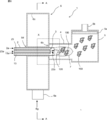
- FIG. 3 is a sectional view of the manufacturing apparatus 1 for manufacturing the carrier powder, which passes through the center of the burner 2. It is an enlarged view of the area
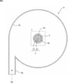
- FIG. 7 is a sectional view taken along line AA in FIG. 6. It is an enlarged view of the area
- Supported metal catalyst 100 As shown in FIGS. 1 to 4, the supported metal catalyst 100 is a carrier powder which is an aggregate of carrier fine particles 150 having a chain portion formed by fusion bonding a plurality of crystallites 120 in a chain shape, The metal fine particles 130 carried by the carrier powder are provided. Each configuration will be described below.
- the carrier fine particles 150 are oxide fine particles containing one or more elements selected from rare earths, alkaline earths, transition metals, niobium, bismuth, tin, antimony, zirconium, molybdenum, indium, tantalum, and tungsten.
- Rare earths, alkaline earths, niobium, bismuth, antimony and tantalum are preferable because they are dopants that improve conductivity, and transition metals are preferable because they are elements that form the matrix that imparts conductivity, and other than the above.
- the elements are preferable because they are elements other than transition metals that constitute the matrix that gives conductivity. Since these fine particles do not dissolve even under strongly acidic conditions, it is preferable that at least one of titanium, iron, niobium, tantalum, zirconium, and tin is contained.
- the carrier fine particles 150 are formed with a branch 160 and a three-dimensional void 110 surrounded by holes existing between the plurality of branches.
- the branch 160 is a portion in which a chain-like portion formed by fusion-bonding a plurality of crystallites 120 constituting the carrier fine particles 150 into a chain is branched as a branch.
- a gas diffusion path for diffusing oxygen, which is an oxidant, and hydrogen, which is a fuel, and transporting it onto the supported metal catalyst 100 is formed by the configuration of the carrier fine particles 150 described above.
- the carrier fine particles 150 have branch points (branch points, sometimes simply referred to as branches hereinafter) b1, b2, b5, A first hole portion surrounded by b4 and b1, a second hole portion surrounded by branch points b1, b2, b3 and b1, a second hole portion surrounded by branch points b2, b3, b6, b7, b5 and b2.
- branch points branch points, sometimes simply referred to as branches hereinafter
- branch points branch points, sometimes simply referred to as branches hereinafter
- branch points b1, b2, b3 and b1 A first hole portion surrounded by branch points b1, b2, b3 and b1, a second hole portion surrounded by branch points b2, b3, b6, b7, b5 and b2.
- Three hole portions, a fourth hole portion surrounded by branch points b1, b3, b6, b7, b5, b4, b1 are provided, so that a total of four hole portions are
- the void 110 is a three-dimensional space surrounded by these four hole surfaces.
- the carrier fine particles 150 have a plurality of holes surrounded by a plurality of branch points connecting a plurality of branches in this way.
- the three-dimensional space (void) surrounded by the plurality of holes is continuously provided. Therefore, this void serves as a gas diffusion path (gas diffusion path) for oxygen and hydrogen.
- FIG. 4 is a diagram showing the gas diffusion path in FIG. FIG. 4 shows an example of the gas diffusion path (gas diffusion path) of the void 110.
- a flow (gas diffusion path) 170 such as an oxidant (gas), a fuel gas, etc. can flow in a desired direction via the void 110 as shown in FIG. That is, the void 110 serves as a gas diffusion path.
- the carrier fine particles 150 may simply have one hole (for example, the first hole surrounded by the branch points b1, b2, b5, b4, b1) as a simple structure.
- the voids 110 are provided by the thickness of the crystallite grains of the crystallite 120.
- the carrier fine particles 150 may have one or more branches. Even in this case, since there is a branch between the carrier fine particles 150, they cannot be adhered to each other, and the void 110 can be provided between them.
- the place described as a hole above may be restated as a closed curve (closed loop).
- the void 110 is surrounded by a closed curved surface including a plurality of branch points (for example, branch points b1 to b7).
- the branch points b1 to b7 may be regarded as the center of gravity of the crystallite of the metal oxide that constitutes the carrier fine particles 150 in which the branches are connected to each other, or may be any one point on the crystallite.
- the size of the crystallite 120 is preferably 10 to 30 nm, more preferably 10 to 15 nm. Specifically, this size is, for example, 10, 11, 12, 13, 14, 15, 16, 17, 18, 19, 20, 25, 30 nm, and is between any two of the numerical values exemplified here. It may be within the range.
- the size (crystallite diameter) of the crystallite 120 can be obtained from the half width of the peak of the XRD pattern based on the Scherrer equation. If the crystallite 120 is too small, the oxide is likely to be eluted and the durability of the catalyst may be reduced. If the crystallite 120 is too large, the volume of the secondary pores becomes small, and the flooding phenomenon may occur easily.
- the aggregate of the carrier fine particles 150 is in powder form. Such an aggregate is referred to as "carrier powder”.
- the average particle size of the carrier fine particles 150 in the carrier powder is preferably 0.1 ⁇ m to 4 ⁇ m, more preferably 0.5 ⁇ m to 2 ⁇ m.
- the average particle size of the carrier fine particles 150 can be measured by a laser diffraction / scattering type particle size distribution measuring device.
- the specific surface area of the carrier powder is preferably 12 m 2 / g or more, more preferably 25 m 2 / g or more.
- the specific surface area is, for example, 12 to 100 m 2 / g, and specifically, for example, 12, 15, 20 , 25, 30, 35, 40, 45, 50, 100 m 2 / g, which is exemplified here. It may be in the range between any two of the numerical values. These values are for fine particles of tin oxide, and when other oxides are used, the true density is different from that of tin oxide, and therefore the values per unit weight are different.
- the true density of tin oxide is 6.95 g / cm 3
- the specific surface area per 1 cm 3 can be converted by multiplying the true density by the above numerical value.
- 12m 2 / g is 83.4 ⁇ 83m 2 / cm 3
- 25m 2 / g becomes 173.75 ⁇ 174m 2 / cm 3.
- this value is, for example, 83, 85, 90, 95, 100, 105, 110, 115, 120, 125, 130, 135, 140, 145, 150, 155, 160, 165, 170 m 2 / cm. 3 , and may be within a range between any two of the numerical values exemplified here.
- the voids 110 included in the carrier powder have primary pores having a pore diameter of 25 nm or less determined by the BJH method and secondary pores having a pore diameter of more than 25 nm and 80 nm or less.
- the volume of the secondary holes is 0.045 cm 3 / g or more. Since this numerical value is also the case of fine particles of tin oxide, in order to generalize it, the numerical value per unit volume of the fine carrier particles constituting the carrier powder will be determined.
- the similarly multiplying the true density of the tin oxide 0.045 cm 3 / g, it has a secondary pore volume of 0.31275 ⁇ 0.313cm 3 / cm 3, and the support powder 1 cm 3 per 0.313Cm 3 become.
- the following numerical values per unit weight can be easily generalized (numerical values per unit volume).
- the primary pores and the secondary pores are deeply related to the discharge of water generated by the catalytic reaction, and the primary pores mainly transport the water generated on the catalyst surface to the secondary pores connected to the primary pores.
- the secondary pores mainly serve to transport the water carried from the primary pores to the outside of the catalyst layer. If the volume of the primary holes and the secondary holes is too small, flooding phenomenon easily occurs. In the present embodiment, since the volume of the secondary holes is a relatively large value of 0.045 cm 3 / g or more, the flooding phenomenon is suppressed.
- the volume of the secondary holes is, for example, 0.045 to 0.100 cm 3 / g, and specifically, for example, 0.045, 0.050, 0.055, 0.060, 0.065, 0.070. , 0.075, 0.080, 0.085, 0.090, 0.095, 0.100 cm 3 / g, and may be in the range between any two of the numerical values exemplified here.
- the volume of the secondary pores is, for example, 0.312 ⁇ 0.695cm 3 / cm 3, specifically, for example, 0.312,0.350,0.400,0 .450, 0.500, 0.550, 0.600, 0.650, 0.695 cm 3 / cm 3 , and may be in the range between any two of the numerical values exemplified here.
- volume of primary hole / volume of secondary hole is preferably 0.80 or less.
- the volume of the secondary holes becomes sufficiently large, and the flooding phenomenon is easily suppressed.
- This value is, for example, 0.10 to 0.80, and specifically, for example, 0.10, 0.15, 0.20, 0.25, 0.30, 0.35, 0.40, 0. .45, 0.50, 0.55, 0.60, 0.65, 0.70, 0.75, 0.80, and is in a range between any two of the numerical values exemplified here. Good.
- the carrier powder preferably has a porosity of 50% or more, more preferably 60% or more.
- the porosity is, for example, 50 to 80%, specifically, for example, 50, 55, 60, 65, 70, 75, 80%, and within a range between any two of the numerical values exemplified here. It may be.
- the porosity can be determined by mercury porosimetry or FIB-SEM.
- the carrier powder preferably has an angle of repose of 50 degrees or less, more preferably 45 degrees or less.
- the carrier powder has the same fluidity as wheat flour and is easy to handle.
- This angle of repose is, for example, 20 to 50 degrees, specifically, for example, 20, 25, 30, 35, 40, 45, 50 degrees, and is within a range between any two of the numerical values exemplified here. May be The angle of repose can be obtained by the drop volume method.
- the conductivity of the carrier powder is preferably 0.001 S / cm or more, more preferably 0.01 S / cm or more.
- This electrical conductivity is, for example, 0.01 to 1000 S / cm, and specifically, for example, 0.01, 0.1, 1, 10, 100, 1000 S / cm, and any of the numerical values exemplified here. It may be in the range between the two.
- the conductivity can be measured based on the JIS standard (JIS K 7194).
- the carrier fine particles 150 have a branch 160 composed of a chain portion formed by fusion bonding a plurality of crystallites 120 in a chain shape, and have a property of allowing electrons to flow. As shown in FIGS. 1 to 4, the carrier fine particles 150 have a plurality of branches 160, and the branches form a network via branch points (b1 to b7) where the branches are connected to each other. Therefore, between them, it has an electrically conductive property. Therefore, the branch 160 of the carrier fine particle 150 shown by a dotted line from the point P0 in FIG. 1 itself constitutes the electron conduction path (electron conduction path) 140.
- the fine metal particles 130 are fine particles of metal (eg, platinum) or alloy that can function as a catalyst.
- the average particle size of the large number of metal fine particles 130 carried on the carrier powder is preferably 1 to 20 nm, more preferably 3 to 10 nm. This average particle diameter is specifically, for example, 1, 2, 3, 4, 5, 6, 7, 8, 9, 10, 11, 12, 13, 14, 15, 16, 17, 18, 19, It is 20 nm, and may be in the range between any two of the numerical values exemplified here. If the average particle size of the metal fine particles 130 is less than 1 nm, it dissolves as the electrode reaction proceeds, and if it exceeds 20 nm, the electrochemically active surface area becomes small and desired electrode performance cannot be obtained.
- the average particle diameter of the metal fine particles 130 can be obtained by measuring the diameters of the circumscribing circles of all the metal fine particles 130 shown in the TEM image of the supported metal catalyst 100 and calculating the arithmetic mean thereof.
- the fine metal particles 130 are made of any metal or alloy having a catalytic ability.
- the fine metal particles 130 are preferably composed of only a noble metal or an alloy of a noble metal and a transition metal.
- the metal fine particles 130 may include a core and a skin layer that covers the core.
- the core preferably comprises an alloy of a noble metal and a transition metal.
- the skin layer preferably contains a noble metal. Platinum is preferable as the noble metal, and cobalt (Co) or nickel (Ni) is preferable as the transition element, and cobalt is particularly preferable.
- the amount of the metal fine particles 130 carried is preferably 1 to 50% by mass, more preferably 5 to 25% by mass. This supported amount is, for example, 1, 5, 10, 15, 20, 25, 30, 35, 40, 45, 50% by mass, and is a range between any two of the numerical values exemplified here. May be inside.
- FIG. 5 shows a model diagram of the fuel cell of the present invention. 5, in the fuel cell (fuel cell) 200, the catalyst layer 220A on the anode 201 side, the gas diffusion layer 210A, the catalyst layer 220K on the cathode 202 side, and the gas diffusion layer 210K are opposed to each other with the electrolyte membrane 230 interposed therebetween. Is composed of.
- the anode side gas diffusion layer 210A, the anode side catalyst layer 220A, the electrolyte membrane 230, the cathode side catalyst layer 220K, and the cathode side gas diffusion layer 210K are arranged in this order.
- the cathode side catalyst layer 220K includes the supported metal catalyst 100.
- the anode-side catalyst layer 220A may also include the supported metal catalyst 100, but may include another catalyst.
- the manufacturing apparatus 1 includes a burner 2, a raw material supply unit 3, a reaction tube 4, a recovery unit 5, and a gas storage unit 6.
- the raw material supply unit 3 includes an outer cylinder 13 and a raw material distribution cylinder 23.
- the burner 2 has a cylindrical shape, and the raw material supply unit 3 is arranged inside the burner 2.
- the burner gas 2a is circulated between the burner 2 and the outer cylinder 13.
- the burner gas 2a is used to form a flame 7 at the tip of the burner 2 by ignition.
- the flame 7 forms a high temperature region of 1000 ° C. or higher.
- the burner gas 2a preferably contains a combustible gas such as propane, methane, acetylene, hydrogen or nitrous oxide.
- a mixed gas of oxygen and propane can be used as the burner gas 2a.
- the temperature in the high temperature region is, for example, 1000 to 2000 ° C., and specifically, for example, 1000, 1100, 1200, 1300, 1400, 1500, 1600, 1700, 1800, 1900, 2000 ° C., and the numerical values exemplified here. It may be within a range between any two.
- a raw material solution 23 a for producing a carrier powder is circulated in the raw material distribution cylinder 23.
- a solution containing a metal compound is used.
- the metal compound include fatty acid metal (Sn, Ti, Nb, Ta, W, etc.) salts.
- the carbon number of the fatty acid is, for example, 2 to 20, preferably 4 to 15, and more preferably 6 to 12.
- metal octylates titanium octylate, niobium octylate, tantalum octylate, tungsten octylate, etc.
- the metal compound is preferably dissolved or dispersed in a non-aqueous solvent.
- the mist-forming gas 13a used for forming the mist of the raw material solution 23a is circulated between the outer cylinder 13 and the raw material distribution cylinder 23.
- the mist forming gas 13a and the raw material solution 23a are jetted together from the tip of the raw material supply unit 3, the raw material solution 23a is misted.
- the mist 23b of the raw material solution 23a is sprayed into the flame 7, and the metal compound in the raw material solution 23a undergoes a thermal decomposition reaction in the flame 7 so that the crystallite 120 is fused and bonded in a chain shape to form a chain portion.
- Carrier powder which is an aggregate of carrier fine particles 150 having, is generated.
- the mist-ized gas 13a is oxygen in one example.
- the reaction tube 4 is provided between the collector 5 and the gas storage section 6. A flame 7 is formed in the reaction tube 4.
- the collector 5 is provided with a filter 5a and a gas discharge part 5b. Negative pressure is applied to the gas discharge part 5b. Therefore, an air flow toward the gas discharge part 5b is generated in the collector 5 and the reaction tube 4.
- the gas storage section 6 is cylindrical and has a cooling gas introduction section 6a and a slit 6b.
- the cooling gas 6g is introduced into the gas storage section 6 from the cooling gas introduction section 6a. Since the cooling gas introduction part 6a is oriented in the direction along the tangent line of the inner peripheral wall 6c of the gas storage part 6, the cooling gas 6g introduced into the gas storage part 6 through the cooling gas introduction part 6a is Turn along 6c.
- a burner insertion hole 6d is provided at the center of the gas storage portion 6. The burner 2 is inserted into the burner insertion hole 6d.
- the slit 6b is provided at a position adjacent to the burner insertion hole 6d so as to surround the burner insertion hole 6d.
- the slit 6b is provided so as to surround the burner 2.
- the cooling gas 6g in the gas storage portion 6 is driven by the negative pressure applied to the gas discharge portion 5b and is discharged toward the reaction tube 4 from the slit 6b.
- the cooling gas 6g may be any gas that can cool the produced oxide, and is preferably an inert gas, for example, air.
- the flow rate of the cooling gas 6g is preferably twice or more the flow rate of the burner gas 2a.
- the upper limit of the flow rate of the cooling gas 6g is not particularly specified, but is, for example, 1000 times the flow rate of the burner gas 2a.
- the flow rate of the cooling gas 6g / the flow rate of the burner gas 2a is, for example, 2 to 1000, and specifically, for example, 2, 5, 10, 15, 20, 25, 30, 35, 40, 45, 50, 100, 200, 500, 1000, and may be in the range between any two of the numerical values exemplified here.
- the cooling gas 6g is caused to flow by applying a negative pressure to the gas discharge part 5b, but the cooling gas 6g may be caused to flow by applying a positive pressure to the cooling gas introduction part 6a.
- the cooling gas 6g since the cooling gas 6g is supplied to the periphery of the flame 7 through the slit 6b, the cooling gas 6g becomes a laminar flow and flows around the flame 7. For this reason, the mist 23b, the crystallites 120, and the carrier fine particles 150 are not disturbed by the cooling gas 6g and are sufficiently heated by the flame 7 while moving along the flame 7 and the reaction proceeds. Further, after the carrier fine particles 150 are emitted from the flame 7, the carrier fine particles 150 are immediately cooled by the cooling gas 6g, so that the structure having the chain-like portion is maintained. The cooled carrier particles 150 are captured and collected by the filter 5a.
- the carrier powder which is an aggregate of the carrier fine particles 150, uses the manufacturing apparatus 1 to form a high temperature region of 1000 ° C. or higher by the flame 7 at the tip of the burner 2, and the cooling gas 6 g is supplied to the high temperature region through the slit 6b. It can be produced by subjecting the metal compound to a thermal decomposition reaction in this high temperature region while supplying it to the surroundings of.
- the high temperature region may be formed by plasma or the like other than the flame 7.
- the method of manufacturing supported metal catalyst 100 includes a carrier powder generating step, a supporting step, a heat treatment step, and a reducing step.
- the carrier powder is produced by the above method.
- the metal fine particles 130 are carried on the carrier powder.
- This loading can be performed using a method such as a reverse micelle method, a colloid method, an impregnation method, or the like.
- metal colloid particles are adsorbed on the carrier powder. More specifically, by preparing a dispersion liquid in which metal colloid particles synthesized by the colloid method are dispersed in an aqueous solution, and adding and mixing the metal colloid particles in the dispersion liquid, the colloid particles on the surface of the carrier powder. Adsorb.
- the carrier powder to which the colloidal particles are adsorbed can be separated from the dispersion medium through filtration and drying.
- heat treatment step heat treatment is performed at 500 to 750 ° C.
- the crystallites of the carrier powder grow and grow in size.
- the carrying step is performed by the colloid method, the colloid particles become the metal fine particles 130.
- This heat treatment is specifically, for example, 500, 550, 600, 650, 700, and 750 ° C., and may be within a range between any two of the numerical values exemplified here.
- crystallites grow, but if the heat treatment temperature is too low, the crystallites 120 of the carrier fine particles 150 do not grow sufficiently and are easily eluted.
- the higher the heat treatment temperature the smaller the secondary pore volume. Therefore, if the heat treatment temperature is too high, the secondary pore volume becomes too small and the flooding phenomenon easily occurs.
- the heat treatment time is, for example, 0.1 to 20 hours, preferably 0.5 to 5 hours. Specifically, this time is, for example, 0.1, 0.5, 1, 2, 3, 4, 5, 6, 7, 8, 9, 10, 15, 20 hours, and the numerical values exemplified here. It may be within a range between any two.
- the heat treatment can be performed in an inert gas atmosphere such as nitrogen or in an inert gas atmosphere containing 1 to 4% hydrogen.
- the reduction treatment of the metal fine particles 130 is performed after the heat treatment step.
- the reduction treatment can be performed by performing heat treatment in a reducing atmosphere containing a reducing gas such as hydrogen.
- the reduction step can be omitted if unnecessary.
- the temperature of this heat treatment is, for example, 70 to 300 ° C, preferably 100 to 200 ° C.
- This temperature is, for example, specifically, 70, 80, 90, 100, 110, 120, 130, 140, 150, 160, 170, 180, 190, 200, 250, 300 ° C., and is exemplified here. It may be in the range between any two of the numerical values.
- the time of this heat treatment is, for example, 0.01 to 20 hours, preferably 0.1 to 5 hours. This time is specifically 0.01, 0.05, 0.1, 0.5, 1, 2, 3, 4, 5, 6, 7, 8, 9, 10, 15, 20 hours. And may be within a range between any two of the numerical values exemplified here.
- the reducing gas is hydrogen
- its concentration is, for example, 0.1 to 100% by volume, preferably 0.2 to 10% by volume, and more preferably 0.5 to 3% by volume.
- This concentration is, for example, 0.1, 0.2, 0.5, 1, 1.5, 2, 2.5, 3, 10, 100% by volume. It may be in the range between any two.
- the metal fine particles 130 after the heat treatment in the heat treatment step may be in an oxidized state, and in that case, the metal fine particles 130 may not show catalytic activity. In this case, the catalytic activity can be increased by reducing the metal fine particles 130.
- Carrier powder was manufactured using the manufacturing apparatus 1 shown in FIGS. 6 to 9.
- the burner gas 2a a gas obtained by mixing 5 L / min of oxygen and 1 L / min of propane gas was used, and this gas was ignited to form a flame (chemical flame) 7 at 1600 ° C. or higher at the tip of the burner 2.
- the raw material solution 23a a solution in which tin octylate and niobium octylate were mixed and dissolved in a mineral split terpene at a molar ratio of 0.95: 0.05 was used.
- Oxygen was used as the mist forming gas 13a.
- the raw material supply unit 3 has a double pipe structure (total length 322.3 mm), oxygen gas is supplied from the outer cylinder 13, a raw material solution 23a is supplied to the raw material distribution cylinder 23, and a fluid nozzle and an air nozzle are provided at the tip of the raw material distribution cylinder 23. Then, there, the raw material solution 23a was made into the mist 23b.
- the recovery amount of the carrier powder was 10 g or more after the operation for 60 minutes.
- the solution was diluted with 150 ml of water and the pH of the solution was adjusted to 5 with NaOH. Then, 25 ml of hydrogen peroxide was added, and the pH was readjusted to 5 with NaOH. Furthermore, a CoCl 2 solution (CoCl 2 (manufactured by Kanto Kagaku) / 15 mL ultrapure water) was added dropwise at 2 mL / min and stirred.
- a CoCl 2 solution CoCl 2 (manufactured by Kanto Kagaku) / 15 mL ultrapure water
- the sample of the heat treatment step was subjected to heat treatment in 1% hydrogen at 150 ° C. for 2 hours to reduce the metal fine particles 130.
- the supported metal catalyst 100 in which the metal fine particles 130 are supported on the carrier powder was obtained.
- Examples 2 to 3 and Comparative Example 1> A supported metal catalyst 100 was obtained in the same manner as in Example 1 except that the heat treatment temperature in step S5 was changed as shown in Table 1.
- BET specific surface area was calculated
- the pore volume distribution was obtained by using the BJH method in the nitrogen gas adsorption process under the conditions of a relative pressure of 0.01 to 0.98 using the above measuring device.
- the total volume of pores having a pore size of 25 nm or less in the obtained distribution was defined as a primary pore volume, and the total volume of pores having a pore size of more than 25 nm and 80 nm or less was defined as a secondary pore volume.
- Examples 1 to 3 which were heat-treated at 500 to 700 ° C. had higher mass activity in a high humidity environment of 80 to 100% humidity than Comparative Example 1 which was heat-treated at 800 ° C. This result is considered to be because the occurrence of the flooding phenomenon was suppressed in Examples 1 to 3 because the secondary pore volume was 0.045 cm 3 / g or more.
- the crystallite size was sufficiently large at 12 to 14 nm, so that the elution of crystallites was sufficiently suppressed.
Landscapes
- Chemical & Material Sciences (AREA)
- Engineering & Computer Science (AREA)
- Chemical Kinetics & Catalysis (AREA)
- Materials Engineering (AREA)
- Organic Chemistry (AREA)
- Electrochemistry (AREA)
- General Chemical & Material Sciences (AREA)
- Manufacturing & Machinery (AREA)
- Physics & Mathematics (AREA)
- Thermal Sciences (AREA)
- Catalysts (AREA)
- Nanotechnology (AREA)
- Inert Electrodes (AREA)
- Fuel Cell (AREA)
- Crystallography & Structural Chemistry (AREA)
Abstract
Priority Applications (4)
| Application Number | Priority Date | Filing Date | Title |
|---|---|---|---|
| CN201980060899.7A CN112714671B (zh) | 2018-10-19 | 2019-10-16 | 负载型金属催化剂及其制造方法 |
| JP2020553230A JP7309154B2 (ja) | 2018-10-19 | 2019-10-16 | 担持金属触媒 |
| EP19873654.8A EP3868473B1 (fr) | 2018-10-19 | 2019-10-16 | Procédé de production d'un catalyseur métallique sur support |
| US17/286,785 US11752490B2 (en) | 2018-10-19 | 2019-10-16 | Supported metal catalyst and method for producing same |
Applications Claiming Priority (2)
| Application Number | Priority Date | Filing Date | Title |
|---|---|---|---|
| JP2018-197385 | 2018-10-19 | ||
| JP2018197385 | 2018-10-19 |
Publications (1)
| Publication Number | Publication Date |
|---|---|
| WO2020080400A1 true WO2020080400A1 (fr) | 2020-04-23 |
Family
ID=70283793
Family Applications (1)
| Application Number | Title | Priority Date | Filing Date |
|---|---|---|---|
| PCT/JP2019/040661 Ceased WO2020080400A1 (fr) | 2018-10-19 | 2019-10-16 | Catalyseur métallique sur support et son procédé de production |
Country Status (5)
| Country | Link |
|---|---|
| US (1) | US11752490B2 (fr) |
| EP (1) | EP3868473B1 (fr) |
| JP (1) | JP7309154B2 (fr) |
| CN (1) | CN112714671B (fr) |
| WO (1) | WO2020080400A1 (fr) |
Cited By (4)
| Publication number | Priority date | Publication date | Assignee | Title |
|---|---|---|---|---|
| WO2021251341A1 (fr) * | 2020-06-11 | 2021-12-16 | 国立大学法人山梨大学 | Catalyseur d'électrode et cellule électrochimique à membrane échangeuse d'anions |
| WO2022045004A1 (fr) * | 2020-08-25 | 2022-03-03 | 国立大学法人山梨大学 | Catalyseur métallique supporté |
| JP2023139622A (ja) * | 2022-03-22 | 2023-10-04 | 株式会社豊田中央研究所 | 触媒層 |
| JP7636757B1 (ja) | 2023-09-08 | 2025-02-27 | 株式会社キャタラー | 導電性金属酸化物粒子及び電気化学反応用触媒粒子 |
Families Citing this family (1)
| Publication number | Priority date | Publication date | Assignee | Title |
|---|---|---|---|---|
| JP7504542B2 (ja) * | 2020-11-12 | 2024-06-24 | 株式会社豊田中央研究所 | 多孔質酸化物半導体粒子 |
Citations (4)
| Publication number | Priority date | Publication date | Assignee | Title |
|---|---|---|---|---|
| WO2005040038A1 (fr) * | 2003-10-23 | 2005-05-06 | Zempachi Ogumi | Procede et dispositif pour produire des particules fines |
| JP2009302044A (ja) * | 2008-05-14 | 2009-12-24 | Tokyo Institute Of Technology | 無機物粒子の製造方法、及びそれを用いた二次電池正極並びに二次電池 |
| WO2011065471A1 (fr) * | 2009-11-27 | 2011-06-03 | 国立大学法人山梨大学 | Porteur de charge à haut potentiel stable à base d'oxyde destiné à une pile à combustible polymère solide |
| JP2017157353A (ja) * | 2016-02-29 | 2017-09-07 | 国立大学法人山梨大学 | 合金電極触媒およびにそれを用いた燃料電池 |
Family Cites Families (9)
| Publication number | Priority date | Publication date | Assignee | Title |
|---|---|---|---|---|
| JP2002184414A (ja) | 2000-12-15 | 2002-06-28 | Asahi Glass Co Ltd | ガス拡散電極の製造方法及び固体高分子型燃料電池の製造方法 |
| US20030186805A1 (en) * | 2002-03-28 | 2003-10-02 | Vanderspurt Thomas Henry | Ceria-based mixed-metal oxide structure, including method of making and use |
| CN102811811B (zh) * | 2010-03-08 | 2015-11-25 | 新加坡国立大学 | 通过溶胶凝胶封装法将Ni纳米畴植入难熔金属氧化物载体——一种有效地解决天然气部分氧化中生焦的方案 |
| JP5730751B2 (ja) * | 2011-12-16 | 2015-06-10 | 国立大学法人 宮崎大学 | 燃料電池用白金・チタン酸化物・チタンカーバイド複合触媒及びその製造方法、並びに当該複合触媒を用いた燃料電池用膜・電極接合体 |
| JP6471979B2 (ja) | 2013-10-03 | 2019-02-20 | 国立大学法人山梨大学 | 電極触媒及びその製造方法 |
| JP6497525B2 (ja) * | 2014-03-28 | 2019-04-10 | 国立大学法人山梨大学 | 電極触媒および電極触媒の製造方法 |
| JP6703911B2 (ja) | 2016-07-14 | 2020-06-03 | 日本製鉄株式会社 | 燃料電池用触媒層、触媒担体用炭素材料、及び触媒担体用炭素材料の製造方法 |
| US10727496B2 (en) | 2016-07-14 | 2020-07-28 | Ford Global Technologies, Llc | Fuel cell oxidation reduction reaction catalyst |
| JP6768386B2 (ja) | 2016-07-21 | 2020-10-14 | 日鉄ケミカル&マテリアル株式会社 | 多孔質炭素材料、固体高分子形燃料電池用触媒および固体高分子形燃料電池ならびに多孔質炭素材料の製造方法 |
-
2019
- 2019-10-16 WO PCT/JP2019/040661 patent/WO2020080400A1/fr not_active Ceased
- 2019-10-16 CN CN201980060899.7A patent/CN112714671B/zh active Active
- 2019-10-16 EP EP19873654.8A patent/EP3868473B1/fr active Active
- 2019-10-16 US US17/286,785 patent/US11752490B2/en active Active
- 2019-10-16 JP JP2020553230A patent/JP7309154B2/ja active Active
Patent Citations (4)
| Publication number | Priority date | Publication date | Assignee | Title |
|---|---|---|---|---|
| WO2005040038A1 (fr) * | 2003-10-23 | 2005-05-06 | Zempachi Ogumi | Procede et dispositif pour produire des particules fines |
| JP2009302044A (ja) * | 2008-05-14 | 2009-12-24 | Tokyo Institute Of Technology | 無機物粒子の製造方法、及びそれを用いた二次電池正極並びに二次電池 |
| WO2011065471A1 (fr) * | 2009-11-27 | 2011-06-03 | 国立大学法人山梨大学 | Porteur de charge à haut potentiel stable à base d'oxyde destiné à une pile à combustible polymère solide |
| JP2017157353A (ja) * | 2016-02-29 | 2017-09-07 | 国立大学法人山梨大学 | 合金電極触媒およびにそれを用いた燃料電池 |
Non-Patent Citations (1)
| Title |
|---|
| J. ELECTROCHEM. SOC., vol. 162, no. 7, 2015, pages F736 - F743 |
Cited By (9)
| Publication number | Priority date | Publication date | Assignee | Title |
|---|---|---|---|---|
| WO2021251341A1 (fr) * | 2020-06-11 | 2021-12-16 | 国立大学法人山梨大学 | Catalyseur d'électrode et cellule électrochimique à membrane échangeuse d'anions |
| US12548781B2 (en) | 2020-06-11 | 2026-02-10 | University Of Yamanashi | Electrode catalyst, and anion exchange membrane electrochemical cell |
| WO2022045004A1 (fr) * | 2020-08-25 | 2022-03-03 | 国立大学法人山梨大学 | Catalyseur métallique supporté |
| CN116018204A (zh) * | 2020-08-25 | 2023-04-25 | 国立大学法人山梨大学 | 负载型金属催化剂 |
| JP2023139622A (ja) * | 2022-03-22 | 2023-10-04 | 株式会社豊田中央研究所 | 触媒層 |
| JP7475798B2 (ja) | 2022-03-22 | 2024-04-30 | 株式会社豊田中央研究所 | 触媒層 |
| JP7636757B1 (ja) | 2023-09-08 | 2025-02-27 | 株式会社キャタラー | 導電性金属酸化物粒子及び電気化学反応用触媒粒子 |
| WO2025052799A1 (fr) | 2023-09-08 | 2025-03-13 | 株式会社キャタラー | Particule d'oxyde métallique conducteur et particule de catalyseur pour réaction électrochimique |
| JP2025039297A (ja) * | 2023-09-08 | 2025-03-21 | 株式会社キャタラー | 導電性金属酸化物粒子及び電気化学反応用触媒粒子 |
Also Published As
| Publication number | Publication date |
|---|---|
| EP3868473B1 (fr) | 2026-02-25 |
| US11752490B2 (en) | 2023-09-12 |
| JPWO2020080400A1 (ja) | 2021-09-16 |
| EP3868473A4 (fr) | 2021-12-22 |
| JP7309154B2 (ja) | 2023-07-18 |
| US20210339224A1 (en) | 2021-11-04 |
| CN112714671B (zh) | 2023-08-15 |
| EP3868473A1 (fr) | 2021-08-25 |
| CN112714671A (zh) | 2021-04-27 |
Similar Documents
| Publication | Publication Date | Title |
|---|---|---|
| JP7309154B2 (ja) | 担持金属触媒 | |
| Liu et al. | A facile synthesis of CoFe 2 O 4/biocarbon nanocomposites as efficient bi-functional electrocatalysts for the oxygen reduction and oxygen evolution reaction | |
| Mao et al. | High-performance bi-functional electrocatalysts of 3D crumpled graphene–cobalt oxide nanohybrids for oxygen reduction and evolution reactions | |
| CN100593016C (zh) | 短碳纳米管、浸渍有催化剂的碳纳米管和燃料电池 | |
| CN101595584B (zh) | 燃料电池电极用的纳米线负载催化剂 | |
| Huang et al. | Novel graphite-carbon encased tungsten carbide nanocomposites by solid-state reaction and their ORR electrocatalytic performance in alkaline medium | |
| CN105521804B (zh) | 一种蜂窝状石墨烯/碳化钨/铂金复合电催化剂的制备方法与应用 | |
| JP7086338B2 (ja) | 担体粉末及びその製造方法、担持金属触媒及びその製造方法 | |
| JP2002298861A (ja) | 燃料電池、燃料電池用電極およびその製造方法 | |
| Huang et al. | High temperature shock (HTS) synthesis of carbon‐based nanomaterials for electrochemical applications | |
| Illathvalappil et al. | Nitrogen-doped graphene anchored with mixed growth patterns of CuPt alloy nanoparticles as a highly efficient and durable electrocatalyst for the oxygen reduction reaction in an alkaline medium | |
| Li et al. | Hollow hemisphere-shaped macroporous graphene/tungsten carbide/platinum nanocomposite as an efficient electrocatalyst for the oxygen reduction reaction | |
| JP7025636B2 (ja) | 担持金属触媒及びその製造方法 | |
| Lüsi et al. | Oxygen reduction reaction on Pd nanocatalysts prepared by plasma-assisted synthesis on different carbon nanomaterials | |
| US10230114B2 (en) | Oxygen reduction catalyst, uses thereof and production process therefor | |
| KR101013600B1 (ko) | 콜로이달-임프린티드 탄소구조체, 그의 제조방법 및 이를이용한 연료전지 전극용 ci 탄소 담지 촉매 | |
| JP2017091736A (ja) | 積層体及びその製造方法、燃料電池用膜電極接合体、固体高分子形燃料電池、並びに、直接メタノール形燃料電池 | |
| JP7190099B2 (ja) | 担持金属触媒及びその製造方法、燃料電池セル | |
| JP7678452B2 (ja) | 担持金属触媒、電気化学セル | |
| JP4037814B2 (ja) | 燃料電池用膜−電極接合体及び燃料電池 | |
| JP7781424B2 (ja) | 担持金属触媒 | |
| WO2024143230A1 (fr) | Catalyseur d'électrode et cellule électrochimique de type à membrane échangeuse d'anions | |
| JP2005270687A (ja) | 触媒担持炭素材およびその製造方法 | |
| Chang et al. | Rambutan-like CNT-Al2O3 scaffolds for high-performance cathode catalyst layers of polymer electrolyte fuel cells | |
| WO2022145349A1 (fr) | Catalyseur métallique supporté |
Legal Events
| Date | Code | Title | Description |
|---|---|---|---|
| 121 | Ep: the epo has been informed by wipo that ep was designated in this application |
Ref document number: 19873654 Country of ref document: EP Kind code of ref document: A1 |
|
| ENP | Entry into the national phase |
Ref document number: 2020553230 Country of ref document: JP Kind code of ref document: A |
|
| NENP | Non-entry into the national phase |
Ref country code: DE |
|
| ENP | Entry into the national phase |
Ref document number: 2019873654 Country of ref document: EP Effective date: 20210519 |
|
| WWG | Wipo information: grant in national office |
Ref document number: 2019873654 Country of ref document: EP |