WO2020084716A1 - Dispositif de fabrication additive et dispositif de commande de valeur numérique - Google Patents
Dispositif de fabrication additive et dispositif de commande de valeur numérique Download PDFInfo
- Publication number
- WO2020084716A1 WO2020084716A1 PCT/JP2018/039544 JP2018039544W WO2020084716A1 WO 2020084716 A1 WO2020084716 A1 WO 2020084716A1 JP 2018039544 W JP2018039544 W JP 2018039544W WO 2020084716 A1 WO2020084716 A1 WO 2020084716A1
- Authority
- WO
- WIPO (PCT)
- Prior art keywords
- wire
- drive
- manufacturing apparatus
- additional manufacturing
- time point
- Prior art date
- Legal status (The legal status is an assumption and is not a legal conclusion. Google has not performed a legal analysis and makes no representation as to the accuracy of the status listed.)
- Ceased
Links
Images


Classifications
-
- B—PERFORMING OPERATIONS; TRANSPORTING
- B23—MACHINE TOOLS; METAL-WORKING NOT OTHERWISE PROVIDED FOR
- B23K—SOLDERING OR UNSOLDERING; WELDING; CLADDING OR PLATING BY SOLDERING OR WELDING; CUTTING BY APPLYING HEAT LOCALLY, e.g. FLAME CUTTING; WORKING BY LASER BEAM
- B23K26/00—Working by laser beam, e.g. welding, cutting or boring
- B23K26/34—Laser welding for purposes other than joining
- B23K26/342—Build-up welding
-
- B—PERFORMING OPERATIONS; TRANSPORTING
- B23—MACHINE TOOLS; METAL-WORKING NOT OTHERWISE PROVIDED FOR
- B23K—SOLDERING OR UNSOLDERING; WELDING; CLADDING OR PLATING BY SOLDERING OR WELDING; CUTTING BY APPLYING HEAT LOCALLY, e.g. FLAME CUTTING; WORKING BY LASER BEAM
- B23K26/00—Working by laser beam, e.g. welding, cutting or boring
- B23K26/34—Laser welding for purposes other than joining
-
- B—PERFORMING OPERATIONS; TRANSPORTING
- B22—CASTING; POWDER METALLURGY
- B22F—WORKING METALLIC POWDER; MANUFACTURE OF ARTICLES FROM METALLIC POWDER; MAKING METALLIC POWDER; APPARATUS OR DEVICES SPECIALLY ADAPTED FOR METALLIC POWDER
- B22F10/00—Additive manufacturing of workpieces or articles from metallic powder
- B22F10/50—Treatment of workpieces or articles during build-up, e.g. treatments applied to fused layers during build-up
-
- B—PERFORMING OPERATIONS; TRANSPORTING
- B22—CASTING; POWDER METALLURGY
- B22F—WORKING METALLIC POWDER; MANUFACTURE OF ARTICLES FROM METALLIC POWDER; MAKING METALLIC POWDER; APPARATUS OR DEVICES SPECIALLY ADAPTED FOR METALLIC POWDER
- B22F10/00—Additive manufacturing of workpieces or articles from metallic powder
- B22F10/80—Data acquisition or data processing
- B22F10/85—Data acquisition or data processing for controlling or regulating additive manufacturing processes
-
- B—PERFORMING OPERATIONS; TRANSPORTING
- B22—CASTING; POWDER METALLURGY
- B22F—WORKING METALLIC POWDER; MANUFACTURE OF ARTICLES FROM METALLIC POWDER; MAKING METALLIC POWDER; APPARATUS OR DEVICES SPECIALLY ADAPTED FOR METALLIC POWDER
- B22F12/00—Apparatus or devices specially adapted for additive manufacturing; Auxiliary means for additive manufacturing; Combinations of additive manufacturing apparatus or devices with other processing apparatus or devices
- B22F12/30—Platforms or substrates
- B22F12/33—Platforms or substrates translatory in the deposition plane
-
- B—PERFORMING OPERATIONS; TRANSPORTING
- B23—MACHINE TOOLS; METAL-WORKING NOT OTHERWISE PROVIDED FOR
- B23K—SOLDERING OR UNSOLDERING; WELDING; CLADDING OR PLATING BY SOLDERING OR WELDING; CUTTING BY APPLYING HEAT LOCALLY, e.g. FLAME CUTTING; WORKING BY LASER BEAM
- B23K15/00—Electron-beam welding or cutting
- B23K15/0046—Welding
- B23K15/0086—Welding welding for purposes other than joining, e.g. build-up welding
-
- B—PERFORMING OPERATIONS; TRANSPORTING
- B33—ADDITIVE MANUFACTURING TECHNOLOGY
- B33Y—ADDITIVE MANUFACTURING, i.e. MANUFACTURING OF THREE-DIMENSIONAL [3D] OBJECTS BY ADDITIVE DEPOSITION, ADDITIVE AGGLOMERATION OR ADDITIVE LAYERING, e.g. BY 3D PRINTING, STEREOLITHOGRAPHY OR SELECTIVE LASER SINTERING
- B33Y30/00—Apparatus for additive manufacturing; Details thereof or accessories therefor
-
- B—PERFORMING OPERATIONS; TRANSPORTING
- B33—ADDITIVE MANUFACTURING TECHNOLOGY
- B33Y—ADDITIVE MANUFACTURING, i.e. MANUFACTURING OF THREE-DIMENSIONAL [3D] OBJECTS BY ADDITIVE DEPOSITION, ADDITIVE AGGLOMERATION OR ADDITIVE LAYERING, e.g. BY 3D PRINTING, STEREOLITHOGRAPHY OR SELECTIVE LASER SINTERING
- B33Y40/00—Auxiliary operations or equipment, e.g. for material handling
-
- B—PERFORMING OPERATIONS; TRANSPORTING
- B33—ADDITIVE MANUFACTURING TECHNOLOGY
- B33Y—ADDITIVE MANUFACTURING, i.e. MANUFACTURING OF THREE-DIMENSIONAL [3D] OBJECTS BY ADDITIVE DEPOSITION, ADDITIVE AGGLOMERATION OR ADDITIVE LAYERING, e.g. BY 3D PRINTING, STEREOLITHOGRAPHY OR SELECTIVE LASER SINTERING
- B33Y50/00—Data acquisition or data processing for additive manufacturing
- B33Y50/02—Data acquisition or data processing for additive manufacturing for controlling or regulating additive manufacturing processes
-
- Y—GENERAL TAGGING OF NEW TECHNOLOGICAL DEVELOPMENTS; GENERAL TAGGING OF CROSS-SECTIONAL TECHNOLOGIES SPANNING OVER SEVERAL SECTIONS OF THE IPC; TECHNICAL SUBJECTS COVERED BY FORMER USPC CROSS-REFERENCE ART COLLECTIONS [XRACs] AND DIGESTS
- Y02—TECHNOLOGIES OR APPLICATIONS FOR MITIGATION OR ADAPTATION AGAINST CLIMATE CHANGE
- Y02P—CLIMATE CHANGE MITIGATION TECHNOLOGIES IN THE PRODUCTION OR PROCESSING OF GOODS
- Y02P10/00—Technologies related to metal processing
- Y02P10/25—Process efficiency
Definitions
- the present invention relates to an additional manufacturing apparatus that adds a material to a workpiece to manufacture a modeled object and a numerical control apparatus that controls the additional manufacturing apparatus.
- An additional manufacturing device that manufactures a three-dimensional shaped object by the Direct Energy Deposition (DED) method.
- Some additional manufacturing apparatuses manufacture a modeled object by locally melting a material with a beam emitted from a processing head and adding the melted material to a workpiece.
- DED Direct Energy Deposition
- An additional manufacturing apparatus that uses a wire of a metal material as a material moves the irradiation position while supplying the wire to the irradiation position of the beam to form a linear bead, which is a solidified material of the molten metal material.
- the additional manufacturing apparatus retracts the wire from the workpiece while the material is molten before the wire is fixed to the bead at the end portion where the bead formation is stopped.
- Patent Document 1 discloses a method of welding a metal material by irradiating the metal material with a laser beam while supplying the wire with the laser beam, while gradually delaying the supply of the wire at the terminal end of the welded portion. It is disclosed that the irradiation of the laser beam is stopped after the laser beam is separated from the welded portion.
- the additive manufacturing apparatus can reduce the sticking of the wire to the bead, but on the other hand, there is a problem in that the processing quality is deteriorated due to the formation of a lump at the tip of the wire.
- the present invention has been made in view of the above, and an object of the present invention is to obtain an additional manufacturing apparatus capable of improving processing quality.
- the additive manufacturing apparatus adds a material melted by irradiation of a beam to a workpiece to manufacture a modeled object.
- An additional manufacturing apparatus includes a beam source that outputs a beam, and a drive unit that changes a relative position between a material sent from a material supply source and a workpiece.
- the drive unit is capable of performing a first drive for feeding the material from the supply source toward the workpiece and a second drive for pulling the fed material back to the supply source, Based on this, switching from the first drive to the second drive is performed.
- the additional manufacturing apparatus according to the present invention has the effect of improving the processing quality.
- FIG. 6 is a diagram illustrating a comparative example of Embodiment 1.
- FIG. 6 is a diagram for explaining the operation of the additional manufacturing apparatus according to the first embodiment.
- the figure explaining the mode of a laser beam and a wire in the additional manufacturing apparatus shown in FIG. 3 is a flowchart showing a procedure of operations performed by the additional manufacturing apparatus according to the first embodiment.
- FIG. 8 is a diagram for explaining the operation of the additional manufacturing apparatus according to the second embodiment.
- NC Numerical Control
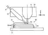
- FIG. 1 is a diagram showing an additional manufacturing apparatus 100 according to the first embodiment of the present invention.
- the additive manufacturing apparatus 100 is a machine tool that manufactures a modeled object by an additive process of adding a material melted by beam irradiation to a workpiece.
- the beam is a laser beam and the material is the wire 5 made of a metallic material.
- the additive manufacturing apparatus 100 forms beads 18 on the base material 17 to form a deposit 18 made of a metal material on the surface of the base material 17.
- the bead is a linear object formed by solidifying the molten wire 5.
- the base material 17 is placed on the stage 15.
- the work piece refers to the base material 17 and the deposit 18.
- the modeled object refers to the base material 17 and the deposit 18 after the addition of the material according to the processing program is completed.
- the base material 17 shown in FIG. 1 is a plate material.
- the base material 17 may be something other than a plate material.
- the additional manufacturing apparatus 100 includes a processing head 10 having a beam nozzle 11, a wire nozzle 12, and a gas nozzle.
- the beam nozzle 11 emits a laser beam that melts a material toward a workpiece.
- the wire nozzle 12 advances the wire 5 toward the irradiation position of the laser beam on the workpiece.
- the gas nozzle ejects a gas for suppressing the oxidation of the deposit 18 and cooling the bead toward the workpiece. In FIG. 1, the illustration of the gas nozzle is omitted.
- the processing head 10 is provided with a temperature sensor 9 and a camera 19.
- the laser oscillator 2 which is a beam source, oscillates a laser beam.
- the laser beam from the laser oscillator 2 propagates to the beam nozzle 11 through the fiber cable 3 which is an optical transmission line.
- the gas supply device 7 supplies gas to the gas nozzle through the pipe 8.
- the gas nozzle ejects gas along the central axis of the laser beam emitted from the beam nozzle 11. That is, the beam nozzle 11 and the gas nozzle are coaxially arranged.
- the gas nozzle may be provided at a position other than the position coaxial with the beam nozzle 11.
- the wire spool 6 around which the wire 5 is wound is a material supply source.
- the rotary motor 4 is a supply drive unit for supplying the material.
- the wire spool 6 rotates as the rotary motor 4, which is a servo motor, is driven to rotate.
- the rotary motor 4 performs a first drive for feeding the wire 5 from the wire spool 6 toward the workpiece, and a second drive for pulling the fed wire 5 back to the wire spool 6.
- the rotary motor 4 rotates the wire spool 6 in the first direction by the first drive, and rotates the wire spool 6 in the second direction opposite to the first direction by the second drive.
- the first direction is the counterclockwise direction and the second direction is the clockwise direction.
- the rotary motor 4 switches from the first drive to the second drive based on the machining program.
- the rotary motor 4 changes the relative position between the tip of the wire 5 sent from the wire spool 6 and the workpiece by switching from the first drive to the second drive.
- the wire 5 sent from the wire spool 6 is passed through the wire nozzle 12 and supplied to the laser beam irradiation position.
- the wire nozzle 12 may be provided with an operation mechanism for pulling out the wire 5 from the wire spool 6.
- the additional manufacturing apparatus 100 is provided with at least one of the rotation motor 4 connected to the wire spool 6 and the operation mechanism of the wire nozzle 12, so that the wire 5 can be supplied to the irradiation position of the laser beam.
- Such an operating mechanism is a feeding drive for feeding the material.
- FIG. 1 the illustration of the operation mechanism of the wire nozzle 12 is omitted.
- the head drive unit 14 moves the processing head 10 in each of the X-axis direction, the Y-axis direction, and the Z-axis direction.
- the X axis, the Y axis, and the Z axis are three axes that are perpendicular to each other.
- the X axis and the Y axis are axes parallel to the horizontal direction.
- the Z-axis direction is the vertical direction.
- the direction indicated by the arrow in the figure may be referred to as the plus X direction, and the direction opposite to the plus X direction may be referred to as the minus X direction.
- the direction indicated by the arrow in the figure may be referred to as the plus Y direction, and the direction opposite to the plus Y direction may be referred to as the minus Y direction.
- the direction indicated by the arrow in the figure may be referred to as the plus Z direction, and the direction opposite to the plus Z direction may be referred to as the minus Z direction.
- the plus Z direction is the vertically upward direction.
- the minus Z direction is the vertically downward direction.
- the head drive unit 14 includes a servo motor that constitutes an operating mechanism for moving the machining head 10 in the X-axis direction, a servo motor that constitutes an operating mechanism for moving the machining head 10 in the Y-axis direction, and a Z And a servo motor constituting an operation mechanism for moving the machining head 10 in the axial direction.
- the head drive unit 14 is an operation mechanism that enables translational movement in each of the three axes. In FIG. 1, the illustration of each servo motor is omitted.
- the additional manufacturing apparatus 100 moves the processing head 10 by driving the head driving unit 14 to move the irradiation position of the laser beam on the workpiece.
- the laser beam is advanced from the beam nozzle 11 in the minus Z direction.
- the wire nozzle 12 is provided at a position apart from the beam nozzle 11 in the XY plane and advances the wire 5 in a direction oblique to the Z axis.
- the processing head 10 may move the wire 5 along the central axis of the laser beam emitted from the beam nozzle 11. That is, the beam nozzle 11 and the wire nozzle 12 may be arranged coaxially with each other.
- the beam nozzle 11 may emit a laser beam whose beam cross-sectional shape is adjusted in a ring shape with the wire 5 as the center, or a plurality of beams dispersed around the wire 5 with the wire 5 as the center.
- the laser beam is adjusted so as to converge at the irradiation position of the workpiece.
- the rotary drive unit 16 is an operating mechanism that enables rotary motion about each of the two axes.
- the rotation drive unit 16 has a servo motor that constitutes an operating mechanism for rotating the stage 15 around the Z axis, and a servo motor that constitutes an operating mechanism for rotating the stage 15 around the X axis. In FIG. 1, the illustration of each servo motor is omitted.
- the rotation drive unit 16 rotates the workpiece together with the stage 15.
- the additional manufacturing apparatus 100 can rotate the stage 15 by the rotation driving unit 16 to make the posture of the workpiece suitable for machining.
- the temperature sensor 9 detects the temperature of the work piece including the molten pool in which the material melted on the work piece is stored.
- the camera 19 captures an image of the molten pool.
- the additional manufacturing apparatus 100 adjusts the processing conditions based on the detection result of the temperature sensor 9.
- the additional manufacturing apparatus 100 can perform processing while monitoring the state of the molten pool based on the image data obtained by photographing with the camera 19.
- the NC device 1 controls the additional manufacturing device 100 according to a processing program.
- the NC device 1 controls the head drive unit 14 by outputting an axis command to the head drive unit 14.
- the NC device 1 controls laser oscillation by the laser oscillator 2 by outputting an output command to the laser oscillator 2.
- the output command is the first command for controlling the output of the laser beam.
- the NC device 1 controls the rotary motor 4 by outputting a supply command to the rotary motor 4.
- the supply command is a second command for controlling the first drive and the second drive.
- the NC device 1 controls the first drive to adjust the speed of the wire 5 sent from the wire spool 6 toward the workpiece. Further, the NC device 1 adjusts the speed of the wire 5 pulled back from the workpiece toward the wire spool 6 by controlling the second drive.
- Such speed may be referred to as traveling speed.
- the traveling speed when the wire 5 is delivered from the wire spool 6 represents the supply amount of the material per hour.
- the NC device 1 controls the gas supply amount from the gas supply device 7 to the gas nozzle by outputting a command according to the gas supply amount condition to the gas supply device 7.
- the NC device 1 controls the drive of the rotation drive unit 16 by outputting a rotation command to the rotation drive unit 16.
- the temperature sensor 9 outputs a signal indicating the temperature detection result to the NC device 1.
- the camera 19 outputs the image data obtained by shooting to the NC device 1.
- the NC device 1 adjusts the processing conditions based on the temperature detection result and the image data.
- the NC device 1 may be one of the constituent elements of the additional manufacturing device 100, or may be a device external to the additional manufacturing device 100.
- FIG. 2 is a diagram showing a functional configuration of the NC device 1 that controls the additional manufacturing device 100 shown in FIG.
- a machining program 20 which is an NC program created by a computer aided manufacturing (CAM) device is input to the NC device 1.
- the processing program 20 designates a processing path that is a path for moving the irradiation position of the laser beam by instructing a movement path for moving the processing head 10 with respect to the workpiece placed on the stage 15.
- the NC device 1 has a processing condition table 21 in which data of various processing conditions is stored.
- the machining program 20 includes a command for selecting a machining condition from the machining conditions whose data is stored in the machining condition table 21.
- the NC device 1 includes a program analysis unit 22 that analyzes the machining program 20, and an axis command generation unit 23 that generates an axis command based on the analysis result of the program analysis unit 22.
- the program analysis unit 22 analyzes a movement path along which the processing head 10 is moved, based on the contents of processing described in the processing program.
- the program analysis unit 22 outputs data indicating the analyzed movement route to the axis command generation unit 23.
- the axis command generation unit 23 generates an axis command that is an interpolation point group for each unit time on the movement route.
- the NC device 1 includes a condition setting unit 24 that sets a processing condition, a condition adjusting unit 25 that adjusts the processing condition, and a condition command generation unit 26 that generates a command according to the processing condition.
- the program analysis unit 22 acquires information for specifying the processing conditions from the processing program 20, and outputs the acquired information to the condition setting unit 24.
- the condition setting unit 24 reads out the data of the machining condition designated in the machining program 20 from the machining condition table 21 based on the information from the program analysis unit 22. As a result, the condition setting unit 24 sets a processing condition for additional processing.
- the NC device 1 obtains the data of the specified machining condition from the data of the various machining conditions stored in advance in the machining condition table 21, and additionally, the machining program 20 in which the data of the machining condition is described. It is also possible to obtain the processing condition data based on the above. Also in this case, the program analysis unit 22 can obtain the data of the processing conditions by analyzing the processing program 20. The program analysis unit 22 outputs the obtained processing condition data to the condition adjustment unit 25.
- the condition adjusting unit 25 acquires data of the set processing conditions from the condition setting unit 24 and adjusts the processing conditions. A signal from the temperature sensor 9 is input to the condition adjusting unit 25. The condition adjusting unit 25 adjusts the output of the laser beam or the supply amount of gas based on the detection result of the temperature sensor 9. The condition adjusting unit 25 outputs the adjusted processing condition data to the condition command generating unit 26.
- the condition command generation unit 26 acquires data on the processing conditions from the condition adjustment unit 25 and generates various commands according to the processing conditions.
- the condition command generation unit 26 has an output command generation unit 27 that generates an output command for controlling the output of the laser beam, and a supply command generation unit 28 that generates a supply command for controlling the supply of the wire 5.
- the supply command generation unit 28 generates a supply command that changes the relative position between the tip of the wire 5 delivered from the wire spool 6 and the workpiece.
- the NC device 1 outputs the axis command generated by the axis command generation unit 23, the output command generated by the output command generation unit 27, and the supply command generated by the supply command generation unit 28.
- the head drive unit 14 shown in FIG. 1 includes a servo amplifier 31 that controls the drive of each servo motor included in the head drive unit 14.
- the servo amplifier 31 controls the drive of each servo motor according to the axis command output from the NC device 1.
- the laser oscillator 2 shown in FIG. 1 includes an oscillation control unit 32 that controls laser oscillation.
- the oscillation control unit 32 controls laser oscillation according to the output command output from the NC device 1.
- the rotary motor 4 shown in FIG. 1 has a servo amplifier 33 that controls a rotary operation.
- the servo amplifier 33 controls the drive of the rotary motor 4 according to the supply command output from the NC device 1.
- condition command generation unit 26 outputs a command according to the condition of the gas supply amount to the gas supply device 7.
- the axis command generation unit 23 outputs a rotation command to the rotation drive unit 16. In FIG. 2, the output of the command to the gas supply device 7 and the output of the rotation command to the rotation drive unit 16 are omitted.
- the NC device 1 controls the entire additional manufacturing device 100 by outputting various commands.
- the NC device 1 may adjust the axis command generated by the axis command generating unit 23 or the processing condition by the condition adjusting unit 25 based on the image data acquired from the camera 19.
- FIG. 2 the illustration of the input of image data from the camera 19 to the NC device 1 is omitted.
- Each functional unit of the NC device 1 shown in FIG. 2 is realized by executing a control program, which is a program for executing the control method of the additional manufacturing device 100 according to the first embodiment, using hardware.
- FIG. 3 is a block diagram showing a hardware configuration of the NC device 1 according to the first embodiment.
- the NC device 1 includes a CPU (Central Processing Unit) 41 that executes various processes, a RAM (Random Access Memory) 42 that includes a data storage area, a ROM (Read Only Memory) 43 that is a non-volatile memory, and an external storage device. 44 and an input / output interface 45 for inputting information to the NC device 1 and outputting information from the NC device 1.
- the units shown in FIG. 3 are connected to each other via a bus 46.
- the CPU 41 executes the programs stored in the ROM 43 and the external storage device 44.
- the program analysis unit 22, the axis command generation unit 23, the condition setting unit 24, the condition adjustment unit 25, the condition command generation unit 26, the output command generation unit 27, and the supply command generation unit 28 illustrated in FIG. 2 are realized using the CPU 41. To be done.
- the external storage device 44 is an HDD (Hard Disk Drive) or SSD (Solid State Drive).
- the external storage device 44 stores a control program and various data.
- the external storage device 44 stores the machining program 20 and the machining condition table 21 shown in FIG.
- the ROM 43 is a boot loader such as a BIOS (Basic Input / Output System) or a UEFI (Unified Extensible Firmware Interface) that is a program for basic control of a computer or a controller that is the NC device 1, and controls hardware. Stores software or programs.
- the control program may be stored in the ROM 43.
- the programs stored in the ROM 43 and the external storage device 44 are loaded into the RAM 42.
- the CPU 41 develops the control program in the RAM 42 and executes various processes.
- the input / output interface 45 is a connection interface with a device external to the NC device 1.
- the machining program 20 and the data stored in the machining condition table 21 are input to the input / output interface 45.
- the input / output interface 45 also outputs various commands.
- the NC device 1 may have an input device such as a keyboard or a pointing device and an output device such as a display.
- the control program may be stored in a computer-readable storage medium.
- the NC device 1 may store the control program stored in the storage medium in the external storage device 44.
- the storage medium may be a portable storage medium which is a flexible disk or a flash memory which is a semiconductor memory.
- the control program may be installed from another computer or a server device to a computer or a controller that will be the NC device 1 via a communication network.
- the function of the NC device 1 may be realized by a processing circuit that is dedicated hardware for controlling the additional manufacturing device 100.
- the processing circuit is a single circuit, a composite circuit, a programmed processor, a parallel programmed processor, an ASIC (Application Specific Integrated Circuit), an FPGA (Field-Programmable Gate Array), or a combination thereof.
- ASIC Application Specific Integrated Circuit
- FPGA Field-Programmable Gate Array
- Some of the functions of the NC device 1 may be realized by dedicated hardware, and the other part may be realized by software or firmware.
- FIG. 4 is a diagram showing a state in which the additional manufacturing apparatus 100 shown in FIG. 1 is forming the beads 50.
- the additional manufacturing apparatus 100 forms the beads 50 by moving the processing head 10 while supplying the wire 5 to the irradiation position of the laser beam.
- the additive manufacturing apparatus 100 moves the processing head 10 in the plus X direction to form the bead 50 having the X-axis direction as the longitudinal direction.
- the bead 50 of the first layer is formed by being directly placed on the base material 17.
- the bead 50 of the second layer is formed by being placed on the bead 50 of the first layer.
- the additive manufacturing apparatus 100 forms the deposit 18 by depositing the plurality of beads 50.
- the additional manufacturing apparatus 100 moves the processing head 10 to a position which becomes the starting point 51 of the bead 50.
- the additional manufacturing apparatus 100 starts moving the processing head 10 in the X-axis direction from the position, irradiating the laser beam, and sending out the wire 5.
- the rotary motor 4 sends the wire 5 from the wire spool 6 to the irradiation position of the laser beam on the base material 17 by the first drive.
- the additional manufacturing apparatus 100 moves the processing head 10 along with the irradiation of the laser beam and the feeding of the wire 5, and the bead 50 is formed by hardening the molten pool 53 due to the temperature decrease.
- the additional manufacturing apparatus 100 stops the movement of the processing head 10, the irradiation of the laser beam, and the sending out of the wire 5.
- the additional manufacturing apparatus 100 thus forms one bead 50.
- the additional manufacturing apparatus 100 causes the rotation motor 4 to rotate the wire spool 6 in the second direction, thereby pulling the wire 5 back to the wire spool 6.
- the additional manufacturing apparatus 100 moves the processing head 10 to the position that will be the starting point 51 of the next bead 50.
- the additional manufacturing apparatus 100 may form the next deposit 18 after finishing the formation of one deposit 18, or the formation of the plurality of deposits 18 may be performed. May be done in parallel.
- the formation of a plurality of deposits 18 in parallel means that the bead 50 of the first layer of each deposit 18 is formed and then the bead 50 of the second layer of each deposit 18 is formed. At this point, the formation of a plurality of deposits 18 is promoted.
- FIG. 5 is a diagram illustrating a comparative example of the first embodiment.
- FIG. 5 shows changes in the speed of the processing head 10, the output of the laser beam, and the speed of the wire 5 when the terminal end portion 54 that is the portion including the end point 52 of the bead 50 is formed.
- the vertical axis of the first graph is the speed F of the processing head 10
- the vertical axis of the second graph is the laser beam output P
- the vertical axis of the third graph is The speed V of the wire 5 is shown respectively.
- the horizontal axis of each graph represents time t.
- F1 is the speed value of the processing head 10 specified by the speed command of the processing program 20.
- P1 is the output value of the laser beam according to the processing conditions.
- V1 is the speed value of the wire 5 according to the processing conditions.
- the processing head 10 reaches the terminal end portion 54 at time T0. From time T0 to time T1, the speed F is maintained at F1, the output P is maintained at P1, and the speed V is maintained at V1.
- the additive manufacturing apparatus 100 starts decelerating the processing head 10, reducing the output of the laser beam, and decelerating the wire 5.
- the processing head 10 reaches the end point 52 at time T2 and stops at the end point 52.
- the output of the laser beam and the feeding of the wire 5 are stopped.
- the transition of the speed V when pulling back the wire 5 after time T2 is omitted.
- the tip portion 5 a of the wire 5 is pulled up from the molten pool 53 while the material which is about to be hardened is attached to the tip portion of the wire 5. It is possible. Also in this case, the material is hardened at the tip portion 5a, so that a lump is generated at the tip portion of the wire 5.
- the first cause of the formation of the lump on the wire 5 is that the material is transferred from the molten pool 53 to the tip of the wire 5 by starting the pulling back of the wire 5 after the irradiation of the laser beam is stopped. It may be attached.
- the second cause of the formation of lumps on the wire 5 is that the wire 5 is irradiated with the laser beam after the supply of the wire 5 is stopped, so that the wire 5 melts at a position away from the bead 50. It can be mentioned.
- the supply amount of the material at the starting point 51 is increased as compared with the case where the lump is not generated.
- the shape accuracy of the portion including the starting point 51 may deteriorate.
- part of the material forming the end portion 54 of the bead 50 is removed from the end portion 54 together with the wire 5, so that the shape accuracy of the end portion 54 may deteriorate.
- the wire 5 When the wire 5 is fixed to the bead 50, the wire 5 may be pulled by pulling the wire 5 when the wire 5 is pulled back or when the processing head 10 moves. The cutting of the wire 5 may deteriorate the shape accuracy of the terminal end portion 54. Further, when the rotary motor 4 is driven while the wire 5 is fixed, an excessive load may be applied to the rotary motor 4. When the head drive unit 14 is driven while the wire 5 is fixed, an excessive load may be applied to the head drive unit 14.
- a thermal balance state between the wire 5 and the molten pool 53 when the speed F is F1, the output P is P1, and the speed V is V1 is referred to as a steady state in the following description.
- the thermal balance state between the wire 5 and the molten pool 53 changes from the steady state. I have something to do. Such changes may occur due to changes in the temperature of the work piece. For example, as the bead 50 is deposited on the work piece, the heat capacity of the work piece and the thermal conductivity of the work piece each change, thereby causing a temperature change of the work piece. Clumps may form due to changes in thermal balance. In addition, the wire 5 may be fixed to the bead 50 due to a change in the thermal balance state. As described above, in the case of the comparative example, even if the transitions of the speed F, the output P, and the speed V in the formation of the terminal end portion 54 are accurately controlled, it is difficult to reduce the formation of the lump and the fixation of the wire 5.
- the rotary motor 4 has the third time point between the first time point when the laser oscillator 2 starts decreasing the output from P1 and the second time point when the output of the laser beam is stopped. At the time point, switching from the first drive to the second drive is performed. The rotary motor 4 starts pulling back the wire 5 from the work piece at the third time point by switching the drive from the first drive to the second drive.
- the output command generation unit 27, which is the first command generation unit, causes the laser oscillator 2 to start decreasing the output from P1 at the first time point and outputs the laser beam at the second time point based on the machining program. Generate an output command to stop.
- the supply command generation unit 28, which is the second command generation unit, generates a supply command for switching from the first drive to the second drive at the third time point based on the machining program. That is, the supply command generation unit 28 generates a supply command for starting the pulling back of the wire 5 to the wire spool 6 at the third time point.
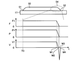
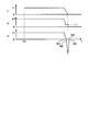
- FIG. 6 is a diagram for explaining the operation of the additional manufacturing apparatus 100 according to the first embodiment.
- FIG. 6 shows changes in the speed of the processing head 10, the output of the laser beam, and the speed of the wire 5 when the terminal end portion 54 of the bead 50 is formed.
- the vertical axis of the first graph is the speed F of the processing head 10
- the vertical axis of the second graph is the laser beam output P
- the vertical axis of the third graph is The speed V of the wire 5 is shown respectively.
- the horizontal axis of each graph represents time t.
- the additional manufacturing apparatus 100 starts decelerating the processing head 10, reducing the output of the laser beam, and decelerating the wire 5.
- the machining head 10 reaches the end point 52 at time M3 and stops at the end point 52.
- the output of the laser beam stops at time M3.
- the additional manufacturing apparatus 100 stops the feeding of the wire 5 at time M2 between time M1 and time M3. Further, the additional manufacturing device 100 starts pulling back the wire 5 at time M2.
- the speed of the wire 5 when the wire 5 is pulled back is decelerated after being accelerated from the time M2.
- the pulling back of the wire 5 stops at time M4 after time M3.
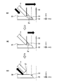
- FIG. 7 is a diagram illustrating a state of the laser beam 55 and the wire 5 in the additional manufacturing apparatus 100 shown in FIG.
- FIG. 7 shows a state of the laser beam 55 and the wire 5 when the end portion 54 of the bead 50 is formed.
- Each of “M1”, “M2”, and “M3” shown in FIG. 7 represents a state at time M1, time M2, and time M3 shown in FIG. 6, respectively.
- Deceleration of the movement of the machining head 10 in the X-axis direction is started at time M1. Also, at time M1, the output of the laser beam 55 starts to decrease. At time M1, the moving speed of the processing head 10 is F1, and the output of the laser beam 55 is P1. Further, deceleration of the speed at which the wire 5 is sent out is started at time M1. At time M1, the speed at which the wire 5 is delivered is V1. At time M1, the molten pool 53 occurs near the center of the laser beam 55 in the XY cross section. In the molten pool 53, the wire 5 and the bead 50 are fused and integrated. The tip 5a of the wire 5 has entered the molten bead 50. The boundary between the wire 5 and the bead 50 may not be clear. In FIG. 7, the boundary between the wire 5 and the bead 50 is schematically represented by a broken line.
- the position of the tip 5a is near the upper end of the molten pool 53.
- the wire 5 is in contact with the upper end of the molten pool 53, so to speak. Further, at time M2, the pulling back of the wire 5 is started. That is, the rotary motor 4 switches from the first drive to the second drive at time M2.
- the pulling back of the wire 5 is started from the state of being in contact with the upper end of the molten pool 53, so that the wire 5 is pulled back from the state of deeply entering the molten pool 53.
- the material adhering to the wire 5 from the molten pool 53 can be reduced.
- the additional manufacturing apparatus 100 can reduce deterioration of the shape accuracy of the terminal end portion 54. Further, the additional manufacturing apparatus 100 can reduce the formation of lumps at the tip 5a.
- the output of the laser beam 55 is stopped. Further, at time M3, the movement of the processing head 10 is stopped. Between the time M2 and the time M3, the wire 5 is pulled back and the machining head 10 moves while continuing to decelerate, whereby the position of the tip portion 5a is further retracted as compared with the time M2. As a result, the position of the tip portion 5a becomes a position outside the irradiation region of the laser beam 55. At time M3, the rotation motor 4 moves the tip 5a of the wire 5 to the outside of the irradiation area of the laser beam 55.
- the irradiation area at time M3 refers to the irradiation area up to immediately before time M3.
- the laser beam 55 that has been output until immediately before time M3 is indicated by a broken line.
- the output command generation unit 27 starts decreasing the output of the laser beam 55 at the first time point when the deceleration of the processing head 10 is started, and at the same time when the processing head 10 is stopped, the second output point is generated.
- An output command for stopping the output of the laser beam 55 is generated at the time point.
- the supply command generation unit 28 decelerates the delivery of the wire 5 at the first time point and pulls back the wire 5 from the delivery of the wire 5 at the third time point between the first time point and the second time point. Generate a supply command to switch to.
- the additional manufacturing apparatus 100 stops the feeding of the wire 5 and starts the pulling back of the wire 5 at time M2 while the output of the laser beam 55 is being reduced.
- the additional manufacturing apparatus 100 can reduce the formation of the lump due to the first factor by starting the pulling back of the wire 5 while the irradiation of the laser beam 55 is continued.
- the additional manufacturing apparatus 100 can shorten the time during which the laser beam 55 is continuously applied to the wire 5 by pulling back the wire 5 from the state in which the tip portion 5a is retracted to the upper end of the bead 50 at time M2. Therefore, the additional manufacturing apparatus 100 can reduce the formation of lumps due to the above second factor.
- the additional manufacturing apparatus 100 can reduce the sticking of the wire 5 to the bead 50 by stopping the feeding of the wire 5 before the irradiation of the laser beam 55 is stopped.
- the rotary motor 4 can retract the tip 5a of the wire 5 from the irradiation area of the laser beam 55 in a short time by performing the second drive that accelerates the speed of pulling back the wire 5 from the time M2. Thereby, the additional manufacturing apparatus 100 can further reduce the formation of lumps due to the second factor.
- the rotary motor 4 may perform a second drive in which the wire 5 is pulled back at a constant speed.
- FIG. 8 is a flowchart showing an operation procedure by the additional manufacturing apparatus 100 according to the first embodiment.
- step S1 the additional manufacturing apparatus 100 starts forming the bead 50 from the starting point 51 shown in FIG.
- step S2 the additional manufacturing apparatus 100 starts decelerating the movement of the processing head 10, reducing the output of the laser beam 55, and decelerating the feeding of the wire 5.
- Step S2 is a process at the time M1.
- step S3 the additional manufacturing apparatus 100 stops the feeding of the wire 5 and starts the pulling back of the wire 5 by switching the first drive to the second drive of the rotary motor 4.
- Step S3 is a process at time M2 described above.
- step S4 the additional manufacturing apparatus 100 stops the movement of the processing head 10 and stops the output of the laser beam 55.
- Step S4 is a process at time M3 described above.
- the additional manufacturing apparatus 100 ends the formation of one bead 50 in step S4.
- step S5 the additional manufacturing apparatus 100 stops the pullback of the wire 5 by stopping the second drive of the rotary motor 4.
- Step S5 is a process at time M4 described above.
- step S6 the additional manufacturing apparatus 100 determines whether or not there is a bead 50 to be formed next.
- step S6 Yes
- the additional manufacturing apparatus 100 moves the processing head 10 to a position which is the starting point 51 of the bead 50 to be formed next, in accordance with the processing program 20 in step S7. To move.
- the additional manufacturing apparatus 100 repeats the procedure from step S1 for the bead 50 to be formed next.
- step S6, No the additional manufacturing apparatus 100 ends the operation according to the procedure shown in FIG.
- the additive manufacturing apparatus 100 starts the first drive at the time between the time when the beam source starts decreasing the output and the time when the output of the beam source stops. Switching to the second drive is performed.
- the additive manufacturing apparatus 100 starts separating the wire 5 from the work piece at a time point between the time point when the beam source starts to decrease the output and the time point when the output of the beam source stops, so that the bead 50 is moved to the bead 50. It is possible to reduce the sticking of the wire 5 and the formation of the lump at the tip 5a of the wire 5.
- the additional manufacturing apparatus 100 can reduce the deterioration of processing quality due to the fixation of the wire 5 and the formation of the lump. Thereby, the additional manufacturing apparatus 100 has an effect that the processing quality can be improved.
- the beam may be a beam other than a laser beam, or may be an electron beam.
- the additional manufacturing apparatus 100 may include an electron beam generation source that is a beam source.
- the NC apparatus 1 can improve the processing quality even when the beam is a beam other than the laser beam.
- FIG. 9 is a diagram showing a functional configuration of the NC device 60 that controls the additional manufacturing device 100 according to the second embodiment of the present invention.
- the additional manufacturing apparatus 100 according to the second embodiment adjusts the time at which the drive unit switches from the first drive to the second drive based on the temperature of the workpiece.
- the same components as those in the above-described first embodiment are designated by the same reference numerals, and configurations different from the first embodiment will be mainly described.
- a signal from the temperature sensor 9 is input to the supply command generation unit 28.
- the supply command generation unit 28 adjusts the third time point based on the detection result of the temperature sensor 9 so that the third time point at which the first drive is switched to the second drive is the temperature of the workpiece. Adjust based on.
- FIG. 9 is the same as FIG. 2 except that an arrow indicating the transmission of a signal from the temperature sensor 9 to the supply command generation unit 28 is added.
- FIG. 10 is a diagram for explaining the operation of the additional manufacturing apparatus 100 according to the second embodiment.
- FIG. 10 shows changes in the output of the laser beam 55 and the speed of the wire 5 when the formation of the beads 50 is stopped.
- the time X1 is the first time point when the laser oscillator 2 starts decreasing the output from P1.
- Time point X2 is the second time point when the output of the laser beam 55 is stopped.
- Time M1 is a time point when the deceleration of the wire 5 is started.
- Time M2 is the third time point when the feeding of the wire 5 is stopped and the pulling back of the wire 5 is started.
- Time M3 is a time when the position of the tip portion 5a of the wire 5 becomes a position outside the irradiation region of the laser beam 55.
- Time M4 is the time when the pulling back of the wire 5 is stopped.
- FIG. 6 described above shows the operation when the time X1 matches the time M1 and the time X2 matches the time M3.
- the operation in such a case is referred to as a reference operation in the following description.
- the temperature detected by the temperature sensor 9 is referred to as the reference temperature. To do.
- the supply command generation unit 28 performs the adjustment to delay the third time point as compared with the case of the reference operation.
- the additional manufacturing apparatus 100 delays the laser beam 55 by delaying the third time point and the time point after the third time point and the position of the tip portion 5a is outside the irradiation area of the laser beam 55. Is pulled out, the wire 5 is pulled out.
- the additional manufacturing apparatus 100 can reduce the amount of heat received by the tip portion 5a of the wire 5 due to the irradiation of the laser beam 55, thereby reducing the formation of lumps due to the second factor.
- the supply command generation unit 28 may make an adjustment to delay the time point at which the deceleration of the feeding of the wire 5 is started after the time X1.
- the additional manufacturing apparatus 100 delays the time point when the deceleration of the wire 5 is started, the third time point, and the time point when the position of the tip 5a is outside the irradiation area of the laser beam 55. be able to.
- the supply command generation unit 28 makes an adjustment to advance the third time point as compared with the case of the reference operation.
- the additional manufacturing apparatus 100 hastens the laser beam 55 by advancing the third time point and the time point after the third time point, when the position of the tip portion 5a is outside the irradiation region of the laser beam 55. Is pulled out, the wire 5 is pulled out.
- the additive manufacturing apparatus 100 can reduce the amount of heat applied to the wire 5 by the irradiation of the laser beam 55, thereby reducing the sticking of the wire 5 to the bead 50.
- the supply command generation unit 28 may make adjustment so that the time point at which the deceleration of the feeding of the wire 5 is started is made earlier than the time X1.
- the additional manufacturing apparatus 100 advances the time point at which the deceleration of the wire 5 is started, the third time point, and the time point when the position of the tip 5a is outside the irradiation area of the laser beam 55. be able to.
- the supply command generation unit 28 may perform adjustment to advance the third time point earlier than the time X1 according to the detected degree of decrease in temperature.
- the additional manufacturing apparatus 100 may perform the adjustment at the third time point based on the temperature by the adjustment by the output instruction generator 27, instead of the adjustment by the supply instruction generator 28.
- the additional manufacturing apparatus 100 adjusts the third time point with respect to the first time point and the second time point by adjusting the time point at which the reduction of the laser output from P1 is started and the time point at which the laser output is stopped. be able to.
- the additional manufacturing apparatus 100 may adjust the third time point based on the temperature of the workpiece by detecting the temperature of the workpiece based on the image data from the camera 19.
- the additive manufacturing apparatus 100 can perform the adjustment at the third time point by using the existing configuration regardless of which of the detection result by the temperature sensor 9 and the image data from the camera 19 is used for the adjustment.
- the additional manufacturing apparatus 100 can reduce the number of parts as compared with the case where a configuration for adjustment at the third time point is separately required.
- the additional manufacturing apparatus 100 may be adjusted using a configuration other than the temperature sensor 9 or the camera 19. Such a configuration may be used only for the adjustment at the third time point.
- the additional manufacturing apparatus 100 may adjust the third time point based on the temperature detection result, or may adjust the third time point based on the workpiece temperature estimation result.
- the additive manufacturing apparatus 100 holds in advance information indicating the relationship between the number of beads 50 to be deposited and the temperature of the deposit 18, and adjusts the third time point based on the estimation result obtained from such information. You may.
- the additive manufacturing apparatus 100 adjusts the time when the drive unit switches from the first drive to the second drive based on the temperature of the workpiece including the molten pool 53. This can reduce the sticking of the wire 5 to the bead 50 and the formation of a lump at the tip 5a of the wire 5.
- the additional manufacturing apparatus 100 can reduce the deterioration of processing quality due to the fixation of the wire 5 and the formation of the lump. Thereby, the additional manufacturing apparatus 100 has an effect that the processing quality can be improved.
- FIG. 11 is a diagram showing a functional configuration of the NC device 70 that controls the additional manufacturing device 100 according to the third embodiment of the present invention.
- the additional manufacturing apparatus 100 according to the third embodiment adjusts the time when the drive unit switches from the first drive to the second drive based on the processing conditions.
- the same components as those in the above-described first and second embodiments are designated by the same reference numerals, and configurations different from those in the first and second embodiments will be mainly described.
- the condition setting unit 24 outputs the processing condition data to the supply command generation unit 28.
- the supply command generation unit 28 adjusts the third time point at which the first drive is switched to the second drive based on the processing conditions.
- FIG. 11 is the same as FIG. 2 except that an arrow indicating the transmission of data from the condition setting unit 24 to the supply command generation unit 28 is added.
- the transition of the output P and the transition of the speed V in the third embodiment are the same as the transition of the output P and the speed V in the second embodiment shown in FIG.
- the relationship between the transition of the output of the laser beam 55 and the transition of the speed of the wire 5 in the third embodiment will be described with reference to FIG. 10.
- the processing conditions when the bead 50 can be formed without causing the wire 5 to be fixed to the bead 50 and the formation of the lump at the tip portion 5a of the wire 5 by the reference operation are referred to as the reference processing conditions.
- the supply command generation unit 28 determines that the temperature of the workpiece is higher than the standard temperature in the adjustment in the second embodiment. Make the same adjustments as you did.
- the wire 5 when the wire 5 has a higher melting point than the wire 5 under the standard processing conditions or a wire 5 thicker than the wire 5 under the standard processing conditions is used, the wire 5 is less likely to melt than the wire under the standard processing conditions. Become.
- the supply command generation unit 28 performs the adjustment in the case where the temperature of the workpiece is lower than the standard temperature among the adjustments in the second embodiment. Make similar adjustments.
- the supply command generation unit 28 performs the same adjustment as the adjustment in the above-described second embodiment when the temperature of the workpiece is lower than the reference temperature.
- a laser beam 55 having a beam diameter larger than the beam diameter of the laser beam 55 under the standard processing conditions is used for processing, or a laser beam 55 having a higher output than the output of the laser beam 55 under the standard processing conditions is generated.
- the supply command generation unit 28 When used for processing, the supply command generation unit 28 performs the same adjustment as that performed when the temperature of the workpiece is higher than the reference temperature among the adjustments in the second embodiment. As a result, the additional manufacturing apparatus 100 can reduce the sticking of the wire 5 and the formation of the lump at the tip 5a of the wire 5, as in the second embodiment.
- the additional manufacturing apparatus 100 may adjust the third time point according to the number of the beads 50 accumulated.
- the temperature of the bead 50 being formed easily decreases due to heat dissipation from the bead 50 to the base material 17.
- the beads 50 of the second and subsequent layers are formed under the same processing conditions as in the case of the first layer, the larger the number of the beads 50 that are deposited, the less likely it is that heat is radiated from the deposit 18. In this case, since the heat accumulated in the deposit 18 increases, the temperature of the formed bead 50 is less likely to decrease.
- the additional manufacturing apparatus 100 adjusts to delay the third time point as the number of the deposited beads 50 increases because the wire 5 is more likely to melt as the number of the deposited beads 50 increases. As a result, the additional manufacturing apparatus 100 can reduce the formation of lumps at the tip 5a of the wire 5, as in the second embodiment.
- the additional manufacturing apparatus 100 may perform the adjustment at the third time point based on the processing condition by the adjustment by the output instruction generator 27 instead of the adjustment by the supply instruction generator 28.
- the additive manufacturing apparatus 100 may perform the adjustment at the third time point based on the temperature of the work piece as in the second embodiment, in addition to the adjustment at the third time point based on the processing condition.
- the additional manufacturing apparatus 100 adjusts the time point at which the drive unit switches from the first drive to the second drive, based on the processing conditions, so as to the second embodiment.
- the adhesion of the wire 5 to the bead 50 and the formation of a lump at the tip 5a of the wire 5 can be reduced.
- the additional manufacturing apparatus 100 has an effect that the processing quality can be improved.
- FIG. 12 is a diagram for explaining the operation of the additional manufacturing apparatus 100 according to the fourth embodiment of the present invention.
- the additional manufacturing apparatus 100 according to the fourth embodiment moves the processing head 10 in a direction away from the workpiece before the time when the drive unit switches the first drive to the second drive.
- the same components as those in the first to third embodiments are designated by the same reference numerals, and configurations different from those in the first to third embodiments will be mainly described.
- the transition of the output P and the transition of the speed V in the fourth embodiment are the same as the transition of the output P and the speed V in the second embodiment shown in FIG.
- the movement of the processing head 10 in the direction away from the work piece is performed at time M1 when the deceleration of the feeding of the wire 5 is started, and when the feeding of the wire 5 is stopped and the pulling back of the wire 5 is started. It is performed at the fourth time point between time M2, which is time point 3 of FIG. In FIG. 12, the direction away from the workpiece is the plus Z direction.
- the fourth time point may be the same as the time point M1. Further, the fourth time point is a time point before the third time point.
- FIG. 12 shows a state before the machining head 10 is moved in the plus Z direction and a state after the machining head 10 is moved in the plus Z direction.
- the tip portion 5a of the wire 5 has deeply entered the molten pool 53 as in the state at time M1 shown in FIG. From this state, the additional manufacturing apparatus 100 moves the processing head 10 in the plus Z direction by the distance ⁇ Z at the fourth time point.
- the position of the tip portion 5a of the wire 5 is raised by the distance ⁇ Z in the plus Z direction from the position at the time of processing along with the movement of the processing head 10, and becomes the position near the upper end of the molten pool 53.
- the axis command generation unit 23 generates an axis command for moving the machining head 10 in the plus Z direction by the distance ⁇ Z at the fourth time point.
- the head drive unit 14 moves the machining head 10 in a direction away from the workpiece at the fourth time point according to the axis command.
- the wire 5 is in contact with the upper end of the molten pool 53, so to speak.
- the pulling back of the wire 5 is started.
- the pulling back of the wire 5 is started from the state of being in contact with the upper end of the molten pool 53, so that the wire 5 is pulled back from the state of deeply entering the molten pool 53.
- the material adhering to the wire 5 from the molten pool 53 can be reduced.
- the additional manufacturing apparatus 100 can reduce deterioration of the shape accuracy of the terminal end portion 54. Further, the additional manufacturing apparatus 100 can reduce the formation of lumps at the tip 5a of the wire 5.
- the additional manufacturing apparatus 100 may perform the adjustment at the third time point based on the temperature of the work piece as in the second embodiment.
- the additional manufacturing apparatus 100 may perform the adjustment at the third time point based on the processing conditions as in the third embodiment.
- the additive manufacturing apparatus 100 moves the machining head 10 in a direction away from the workpiece before the drive unit switches the first drive to the second drive, thereby terminating the end portion.
- the deterioration of the shape accuracy in 54 can be reduced.
- the additional manufacturing apparatus 100 can reduce the formation of lumps at the tip 5a of the wire 5. Thereby, the additional manufacturing apparatus 100 has an effect that the processing quality can be improved.
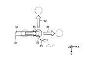
- FIG. 13 is a diagram for explaining the operation of the additional manufacturing apparatus 100 according to the fifth embodiment of the present invention.
- the additive manufacturing apparatus 100 according to the fifth embodiment changes the relative position of the processing head 10 with respect to the workpiece by moving the processing head 10 or rotating the workpiece at a position where the addition of the melted material is stopped. .
- the position where the addition of the melted material is stopped is the position where the end point 52 of the bead 50 is reached.
- the same components as those in the first to fourth embodiments are designated by the same reference numerals, and configurations different from those in the first to fourth embodiments will be mainly described.
- the first movement direction 81 that is the plus X direction and the second movement direction 82 that is the minus Y direction are the machining head 10 when the machining head 10 reaches the end point 52 of the bead 50.
- the rotation direction 83 is an example of the direction in which the workpiece is rotated by the drive of the rotation drive unit 16 when the processing head 10 reaches the position that is the end point 52 of the bead 50.
- the rotation direction 83 is a direction in which the relative distance between the workpiece and the tip portion 5a increases.
- the transition of the output P and the transition of the speed V in the fifth embodiment are the same as the transition of the output P and the speed V in the second embodiment shown in FIG.
- the movement of the processing head 10 and the rotation of the workpiece will be described with reference to FIG.
- the processing head 10 moves at the time M2 in the plus X direction, which is the same direction as the movement direction when the bead 50 is formed.
- the processing head 10 stops moving in the plus X direction and starts moving in the minus Y direction at time M2. .
- the axis command generation unit 23 which is the second command generation unit, generates an axis command that moves the machining head 10 in a preset direction at the position that is the end point 52.
- the head drive unit 14 moves the processing head 10 according to the axis command.
- the machining head 10 stops moving in the plus X direction.
- the rotation drive unit 16 rotates the workpiece in the rotation direction 83.
- the axis command generator 23 generates a rotation command to rotate the work piece in a preset direction at the position of the end point 52.
- the rotation driving unit 16 rotates the stage 15 according to the rotation command.
- the additional manufacturing apparatus 100 changes the relative position of the processing head 10 with respect to the workpiece when the wire 5 is pulled back to the wire spool 6.
- the additional manufacturing apparatus 100 can adjust the shape left at the terminal end portion 54 of the bead 50 to a shape suitable for processing a molded product. As a result, the additional manufacturing apparatus 100 can improve the shape accuracy.
- the direction in which the processing head 10 is moved and the direction in which the workpiece is rotated are not limited to those shown in FIG. 13 and may be arbitrary.
- the change in the relative position of the processing head 10 with respect to the workpiece does not have to be simultaneous with the switching from the first drive to the second drive by the drive unit.
- the additional manufacturing apparatus 100 may change the relative position of the processing head 10 with respect to the workpiece before the switching, and may change the relative position of the processing head 10 with respect to the workpiece after the switching. .
- the additional manufacturing apparatus 100 may not pull back the wire 5 by the rotary motor 4, but may pull back the wire 5 by moving the processing head 10.
- the pulling back of the wire 5 by the movement of the processing head 10 means a state in which the tip 5a is relatively separated from the workpiece toward the wire spool 6 by changing the relative position of the processing head 10 with respect to the workpiece. It means that.
- the rotary motor 4 functions as a drive unit that performs the first drive for feeding the material from the supply source toward the workpiece.
- the head drive unit 14 functions as a drive unit that performs a second drive for returning the fed material to the supply source.
- the rotary motor 4 and the head drive unit 14 switch from the first drive to the second drive based on the machining program.
- the first drive refers to feeding the wire 5 from the wire spool 6 toward the workpiece by the rotary motor 4.
- the second driving refers to moving the processing head 10 in order to change the relative position by the head driving unit 14. Also in this case, the additional manufacturing apparatus 100 can improve the shape accuracy and the processing quality.
- the additional manufacturing apparatus 100 may not pull back the wire 5 by the rotary motor 4, but may pull back the wire 5 by rotating the workpiece.
- the pulling back of the wire 5 due to the rotation of the workpiece means that the tip 5a is relatively pulled away from the workpiece toward the wire spool 6 by changing the relative position of the processing head 10 with respect to the workpiece. It means that.
- the rotary motor 4 functions as a drive unit that performs the first drive for feeding the material from the supply source toward the workpiece.
- the rotation drive unit 16 functions as a drive unit that performs a second drive for returning the fed material to the supply source.
- the rotary motor 4 and the rotary drive unit 16 switch from the first drive to the second drive based on the machining program.
- the first drive refers to feeding the wire 5 from the wire spool 6 toward the workpiece by the rotary motor 4.
- the second drive means that the rotation drive unit 16 rotates the workpiece in order to change the relative position by the rotation drive unit 16. Also in this case, the additional manufacturing apparatus 100 can improve the shape accuracy and the processing quality.
- the additional manufacturing apparatus 100 may change the relative position according to the fifth embodiment in addition to moving the machining head 10 in the plus Z direction according to the fourth embodiment.
- the additive manufacturing apparatus 100 may perform the adjustment at the third time point based on the temperature of the workpiece as in the second embodiment.
- the additional manufacturing apparatus 100 may perform the adjustment at the third time point based on the processing conditions as in the third embodiment.
- the addition manufacturing apparatus 100 can improve the shape accuracy by changing the relative position of the processing head 10 with respect to the workpiece at the position where the addition of the melted material is stopped. Thereby, the additional manufacturing apparatus 100 has an effect that the processing quality can be improved.
- FIG. 14 is a diagram for explaining the operation of the additional manufacturing apparatus 100 according to the sixth embodiment of the present invention.
- the additional manufacturing apparatus 100 according to the sixth embodiment keeps the output of the laser beam 55 constant during the period including the time point when the drive unit switches from the first drive to the second drive.
- the same components as those in the first to fifth embodiments are designated by the same reference numerals, and configurations different from those in the first to fifth embodiments will be mainly described.
- the decrease in the output of the laser beam 55 starts from time M1.
- the output of the laser beam 55 reaches a preset output value L1 before the time M2.
- L1 is an output value lower than P1 and higher than zero.
- the output of the laser beam 55 is maintained at L1 from the time when it reaches L1 to the time M3.
- L1 is an output value capable of maintaining the molten state of the molten pool 53 to the extent that the wire 5 can be separated from the bead 50.
- the output of the laser beam 55 decreases again from time M3 and reaches zero. In this way, the additional manufacturing apparatus 100 makes the output of the laser beam 55 constant during the period including the time M2 that is the third time point. Due to the above operation, the output command generation unit 27 generates an output command that causes the output to reach L1 before time M2 and sets the output to L1 until time M3.
- the additional manufacturing apparatus 100 can pull back the wire 5 from the molten pool 53 in the molten state by irradiating the laser beam 55 of L1 during the period including the third time point.
- the additive manufacturing apparatus 100 can reduce sticking of the wire 5 to the bead 50 by bringing the molten pool 53 into a molten state.
- the additional manufacturing apparatus 100 only needs to be able to bring the molten pool 53 into the molten state while the wire 5 is pulled back, and may appropriately change the length of the period for keeping the output value constant.
- the additional manufacturing apparatus 100 may start decreasing the output from L1 before the time M3.
- L1 may be set based on the detection result of the temperature of the workpiece.
- L1 may be adjusted based on how easily the wire 5 melts.
- the additional manufacturing apparatus 100 may perform the adjustment at the third time point based on the temperature of the work piece as in the second embodiment.
- the additional manufacturing apparatus 100 may perform the adjustment at the third time point based on the processing conditions as in the third embodiment.
- the additional manufacturing apparatus 100 may move the processing head 10 similarly to the fourth embodiment.
- the additional manufacturing apparatus 100 may move the processing head 10 or rotate the workpiece as in the fifth embodiment.
- the additive manufacturing apparatus 100 causes the beads 50 to move to the bead 50 by keeping the output of the laser beam 55 constant during the period including the time point when the driving unit switches from the first driving to the second driving.
- the sticking of the wire 5 can be reduced.
- the additional manufacturing apparatus 100 has an effect that the processing quality can be improved.
Landscapes
- Engineering & Computer Science (AREA)
- Chemical & Material Sciences (AREA)
- Materials Engineering (AREA)
- Manufacturing & Machinery (AREA)
- Physics & Mathematics (AREA)
- Optics & Photonics (AREA)
- Mechanical Engineering (AREA)
- Plasma & Fusion (AREA)
- Laser Beam Processing (AREA)
Abstract
L'invention concerne un dispositif de fabrication additive (100) équipé d'un oscillateur laser (2) qui est une source de faisceau destinée à émettre un faisceau, et d'un moteur rotatif (4) qui est une unité d'entraînement destinée à modifier les positions relatives d'un matériau dévidé d'une bobine de fil (6) servant de source d'alimentation d'un fil (5) qui est le matériau, et un objet à traiter. L'unité d'entraînement est apte à réaliser un premier entraînement afin de dévider le matériau de la source d'alimentation vers l'objet à traiter, et un second entraînement permettant de faire tourner le matériau dévidé et de le retourner à la source d'alimentation, la commutation du premier entraînement au second entraînement étant effectuée sur la base d'un programme de traitement.
Priority Applications (4)
| Application Number | Priority Date | Filing Date | Title |
|---|---|---|---|
| PCT/JP2018/039544 WO2020084716A1 (fr) | 2018-10-24 | 2018-10-24 | Dispositif de fabrication additive et dispositif de commande de valeur numérique |
| US17/283,020 US11331755B2 (en) | 2018-10-24 | 2018-10-24 | Additive manufacturing apparatus and numerical control device |
| JP2019524471A JP6676220B1 (ja) | 2018-10-24 | 2018-10-24 | 付加製造装置および数値制御装置 |
| DE112018008001.3T DE112018008001B4 (de) | 2018-10-24 | 2018-10-24 | 3D-Druckvorrichtung und numerisches Steuergerät |
Applications Claiming Priority (1)
| Application Number | Priority Date | Filing Date | Title |
|---|---|---|---|
| PCT/JP2018/039544 WO2020084716A1 (fr) | 2018-10-24 | 2018-10-24 | Dispositif de fabrication additive et dispositif de commande de valeur numérique |
Publications (1)
| Publication Number | Publication Date |
|---|---|
| WO2020084716A1 true WO2020084716A1 (fr) | 2020-04-30 |
Family
ID=70057994
Family Applications (1)
| Application Number | Title | Priority Date | Filing Date |
|---|---|---|---|
| PCT/JP2018/039544 Ceased WO2020084716A1 (fr) | 2018-10-24 | 2018-10-24 | Dispositif de fabrication additive et dispositif de commande de valeur numérique |
Country Status (4)
| Country | Link |
|---|---|
| US (1) | US11331755B2 (fr) |
| JP (1) | JP6676220B1 (fr) |
| DE (1) | DE112018008001B4 (fr) |
| WO (1) | WO2020084716A1 (fr) |
Cited By (2)
| Publication number | Priority date | Publication date | Assignee | Title |
|---|---|---|---|---|
| US20220270024A1 (en) * | 2021-02-21 | 2022-08-25 | Gloria J. Miller | Method and system to predict stakeholder project impact |
| US12508775B2 (en) | 2020-10-15 | 2025-12-30 | Mitsubishi Electric Corporation | Additive manufacturing method, additive manufacturing apparatus, and additive manufacturing system |
Families Citing this family (3)
| Publication number | Priority date | Publication date | Assignee | Title |
|---|---|---|---|---|
| US20250100077A1 (en) * | 2022-02-16 | 2025-03-27 | Nexa3D, Inc. | Wire oscillation for directed energy deposition |
| CN114749784A (zh) * | 2022-05-07 | 2022-07-15 | 浙江智熔增材制造技术有限公司 | 一种提高电子束熔丝成形零件表面质量的方法 |
| US12533730B2 (en) * | 2022-06-21 | 2026-01-27 | Mitsubishi Electric Corporation | Additive manufacturing apparatus and additive manufacturing method |
Citations (6)
| Publication number | Priority date | Publication date | Assignee | Title |
|---|---|---|---|---|
| JPS58122182A (ja) * | 1981-12-14 | 1983-07-20 | ゼネラル・エレクトリツク・カンパニイ | 溶加材を加工物に溶着中に加熱力を制御する方法と装置 |
| JPH0292479A (ja) * | 1988-09-29 | 1990-04-03 | Mazda Motor Corp | レーザ肉盛方法 |
| JP2001105163A (ja) * | 1999-10-07 | 2001-04-17 | Hitachi Constr Mach Co Ltd | レーザ溶接方法 |
| JP2016518267A (ja) * | 2013-03-22 | 2016-06-23 | マーク,グレゴリー,トーマス | 三次元印刷法 |
| JP2016179501A (ja) * | 2015-03-23 | 2016-10-13 | リンカーン グローバル, インコーポレイテッドLincoln Global, Inc. | 高エネルギー源とホットワイヤを用いた付加製造のための方法とシステム |
| JP2016190426A (ja) * | 2015-03-31 | 2016-11-10 | 武藤工業株式会社 | 三次元造形装置、及びその制御方法 |
Family Cites Families (16)
| Publication number | Priority date | Publication date | Assignee | Title |
|---|---|---|---|---|
| JP3621755B2 (ja) | 1995-06-27 | 2005-02-16 | 石川島播磨重工業株式会社 | 水中レーザ溶接方法 |
| US6046426A (en) * | 1996-07-08 | 2000-04-04 | Sandia Corporation | Method and system for producing complex-shape objects |
| US6459951B1 (en) * | 1999-09-10 | 2002-10-01 | Sandia Corporation | Direct laser additive fabrication system with image feedback control |
| AT512571B1 (de) * | 2012-01-25 | 2013-12-15 | Fronius Int Gmbh | Drahtfördervorrichtung für ein schweissgerät beziehungsweise für einen schweissbrenner |
| US20140021183A1 (en) * | 2012-07-19 | 2014-01-23 | Lincoln Global Inc. | Method and system for gas metal arc welding and a contact tip used for the same |
| WO2015048155A1 (fr) * | 2013-09-24 | 2015-04-02 | Fenner U.S., Inc. | Filament amélioré pour une modélisation par dépôt en fusion |
| US10046419B2 (en) * | 2014-01-24 | 2018-08-14 | Lincoln Global, Inc. | Method and system for additive manufacturing using high energy source and hot-wire |
| US9808886B2 (en) * | 2014-01-24 | 2017-11-07 | Lincoln Global, Inc. | Method and system for additive manufacturing using high energy source and hot-wire |
| US9833862B2 (en) * | 2014-01-24 | 2017-12-05 | Lincoln Global, Inc. | Method and system for additive manufacturing using high energy source and hot-wire |
| US9839978B2 (en) * | 2014-01-24 | 2017-12-12 | Lincoln Global, Inc. | Method and system for additive manufacturing using high energy source and hot-wire |
| US10675698B2 (en) * | 2015-12-31 | 2020-06-09 | Illinois Tool Works Inc. | Wire delivery apparatus with a non-rotational actuator |
| WO2017180116A1 (fr) * | 2016-04-13 | 2017-10-19 | Gkn Aerospace North America Inc. | Système et procédé de fabrication d'additifs |
| DE102016214562B3 (de) * | 2016-08-05 | 2017-10-19 | Trumpf Werkzeugmaschinen Gmbh + Co. Kg | Vorrichtung und Verfahren zum Laserschweißen mit einem Zusatzwerkstoff in Form eines Schweißdrahtes sowie Steuerungsprogramm zur Durchführung des Verfahrens |
| EP3332896A4 (fr) * | 2016-10-05 | 2019-06-19 | Technology Research Association For Future Additiv | Dispositif d'impression 3d, procédé de commande pour dispositif d'impression 3d et programme de commande pour dispositif d'impression 3d |
| DE102017112849A1 (de) * | 2017-03-14 | 2018-09-20 | Scansonic Holding Se | Verfahren und Vorrichtung zur drahtgebundenen additiven Fertigung |
| CN110603119B (zh) * | 2018-04-12 | 2021-07-30 | 三菱电机株式会社 | 附加制造装置、附加制造系统及附加制造方法 |
-
2018
- 2018-10-24 JP JP2019524471A patent/JP6676220B1/ja active Active
- 2018-10-24 WO PCT/JP2018/039544 patent/WO2020084716A1/fr not_active Ceased
- 2018-10-24 US US17/283,020 patent/US11331755B2/en active Active
- 2018-10-24 DE DE112018008001.3T patent/DE112018008001B4/de active Active
Patent Citations (6)
| Publication number | Priority date | Publication date | Assignee | Title |
|---|---|---|---|---|
| JPS58122182A (ja) * | 1981-12-14 | 1983-07-20 | ゼネラル・エレクトリツク・カンパニイ | 溶加材を加工物に溶着中に加熱力を制御する方法と装置 |
| JPH0292479A (ja) * | 1988-09-29 | 1990-04-03 | Mazda Motor Corp | レーザ肉盛方法 |
| JP2001105163A (ja) * | 1999-10-07 | 2001-04-17 | Hitachi Constr Mach Co Ltd | レーザ溶接方法 |
| JP2016518267A (ja) * | 2013-03-22 | 2016-06-23 | マーク,グレゴリー,トーマス | 三次元印刷法 |
| JP2016179501A (ja) * | 2015-03-23 | 2016-10-13 | リンカーン グローバル, インコーポレイテッドLincoln Global, Inc. | 高エネルギー源とホットワイヤを用いた付加製造のための方法とシステム |
| JP2016190426A (ja) * | 2015-03-31 | 2016-11-10 | 武藤工業株式会社 | 三次元造形装置、及びその制御方法 |
Cited By (2)
| Publication number | Priority date | Publication date | Assignee | Title |
|---|---|---|---|---|
| US12508775B2 (en) | 2020-10-15 | 2025-12-30 | Mitsubishi Electric Corporation | Additive manufacturing method, additive manufacturing apparatus, and additive manufacturing system |
| US20220270024A1 (en) * | 2021-02-21 | 2022-08-25 | Gloria J. Miller | Method and system to predict stakeholder project impact |
Also Published As
| Publication number | Publication date |
|---|---|
| JP6676220B1 (ja) | 2020-04-08 |
| JPWO2020084716A1 (ja) | 2021-02-15 |
| DE112018008001B4 (de) | 2024-07-18 |
| US20210308794A1 (en) | 2021-10-07 |
| US11331755B2 (en) | 2022-05-17 |
| DE112018008001T5 (de) | 2021-06-10 |
Similar Documents
| Publication | Publication Date | Title |
|---|---|---|
| JP6676220B1 (ja) | 付加製造装置および数値制御装置 | |
| CN112888525B (zh) | 层叠造形方法以及加工路径生成方法 | |
| US11325190B2 (en) | Additive manufacturing method and machining-path generation method | |
| US11229956B2 (en) | Numerical control device, additive manufacturing apparatus, and method for controlling additive manufacturing apparatus | |
| CN115461185B (zh) | 附加制造装置、附加制造方法及机器学习装置 | |
| JP6877576B2 (ja) | 付加製造装置および付加製造方法 | |
| WO2021005690A1 (fr) | Dispositif de fabrication additive | |
| US10562099B2 (en) | Gradient material control and programming of additive manufacturing processes | |
| JP5201114B2 (ja) | レーザ加工装置およびレーザ加工方法 | |
| CN112912231B (zh) | 数控装置及附加制造装置的控制方法 | |
| JP7023431B1 (ja) | 付加製造装置および付加製造方法 | |
| CN111482601B (zh) | 抑制加减速打印高点的同轴送粉3d激光打印控制方法 | |
| US20200238413A1 (en) | Wire electrical discharge machine, machining program editor, wire electrode moving method and machining program editing method | |
| JP7143964B1 (ja) | 金属積層造形体の製造装置および製造方法 | |
| JP7580682B1 (ja) | 積層造形装置および積層造形方法 | |
| JP2004195467A (ja) | レーザー加工における照射エネルギー制御方法 |
Legal Events
| Date | Code | Title | Description |
|---|---|---|---|
| ENP | Entry into the national phase |
Ref document number: 2019524471 Country of ref document: JP Kind code of ref document: A |
|
| 121 | Ep: the epo has been informed by wipo that ep was designated in this application |
Ref document number: 18937924 Country of ref document: EP Kind code of ref document: A1 |
|
| 122 | Ep: pct application non-entry in european phase |
Ref document number: 18937924 Country of ref document: EP Kind code of ref document: A1 |