WO2020084840A1 - ガラス板の折割機械 - Google Patents
ガラス板の折割機械 Download PDFInfo
- Publication number
- WO2020084840A1 WO2020084840A1 PCT/JP2019/026812 JP2019026812W WO2020084840A1 WO 2020084840 A1 WO2020084840 A1 WO 2020084840A1 JP 2019026812 W JP2019026812 W JP 2019026812W WO 2020084840 A1 WO2020084840 A1 WO 2020084840A1
- Authority
- WO
- WIPO (PCT)
- Prior art keywords
- glass plate
- cutting line
- along
- splitting
- glass
- Prior art date
- Legal status (The legal status is an assumption and is not a legal conclusion. Google has not performed a legal analysis and makes no representation as to the accuracy of the status listed.)
- Ceased
Links
Images






Classifications
-
- C—CHEMISTRY; METALLURGY
- C03—GLASS; MINERAL OR SLAG WOOL
- C03B—MANUFACTURE, SHAPING, OR SUPPLEMENTARY PROCESSES
- C03B33/00—Severing cooled glass
- C03B33/02—Cutting or splitting sheet glass or ribbons; Apparatus or machines therefor
- C03B33/04—Cutting or splitting in curves, especially for making spectacle lenses
-
- B—PERFORMING OPERATIONS; TRANSPORTING
- B26—HAND CUTTING TOOLS; CUTTING; SEVERING
- B26F—PERFORATING; PUNCHING; CUTTING-OUT; STAMPING-OUT; SEVERING BY MEANS OTHER THAN CUTTING
- B26F3/00—Severing by means other than cutting; Apparatus therefor
-
- B—PERFORMING OPERATIONS; TRANSPORTING
- B28—WORKING CEMENT, CLAY, OR STONE
- B28D—WORKING STONE OR STONE-LIKE MATERIALS
- B28D5/00—Fine working of gems, jewels, crystals, e.g. of semiconductor material; apparatus or devices therefor
-
- B—PERFORMING OPERATIONS; TRANSPORTING
- B28—WORKING CEMENT, CLAY, OR STONE
- B28D—WORKING STONE OR STONE-LIKE MATERIALS
- B28D7/00—Accessories specially adapted for use with machines or devices of the preceding groups
- B28D7/04—Accessories specially adapted for use with machines or devices of the preceding groups for supporting or holding work or conveying or discharging work
-
- C—CHEMISTRY; METALLURGY
- C03—GLASS; MINERAL OR SLAG WOOL
- C03B—MANUFACTURE, SHAPING, OR SUPPLEMENTARY PROCESSES
- C03B33/00—Severing cooled glass
- C03B33/02—Cutting or splitting sheet glass or ribbons; Apparatus or machines therefor
- C03B33/023—Cutting or splitting sheet glass or ribbons; Apparatus or machines therefor the sheet or ribbon being in a horizontal position
- C03B33/027—Scoring tool holders; Driving mechanisms therefor
-
- C—CHEMISTRY; METALLURGY
- C03—GLASS; MINERAL OR SLAG WOOL
- C03B—MANUFACTURE, SHAPING, OR SUPPLEMENTARY PROCESSES
- C03B33/00—Severing cooled glass
- C03B33/02—Cutting or splitting sheet glass or ribbons; Apparatus or machines therefor
- C03B33/023—Cutting or splitting sheet glass or ribbons; Apparatus or machines therefor the sheet or ribbon being in a horizontal position
- C03B33/03—Glass cutting tables; Apparatus for transporting or handling sheet glass during the cutting or breaking operations
-
- C—CHEMISTRY; METALLURGY
- C03—GLASS; MINERAL OR SLAG WOOL
- C03B—MANUFACTURE, SHAPING, OR SUPPLEMENTARY PROCESSES
- C03B33/00—Severing cooled glass
- C03B33/02—Cutting or splitting sheet glass or ribbons; Apparatus or machines therefor
- C03B33/023—Cutting or splitting sheet glass or ribbons; Apparatus or machines therefor the sheet or ribbon being in a horizontal position
- C03B33/033—Apparatus for opening score lines in glass sheets
Definitions
- the present invention relates to a glass plate breaking machine.
- the glass plate receiving surface of the glass plate receiving device when pushing and breaking the glass plate along the cutting line, generally, the glass plate receiving surface of the glass plate receiving device is arranged on the lower surface of the glass plate, and the glass plate receiving surface is the lower surface. Since the push bar is pressed against one part of the upper surface of the glass plate supported by one after another to break the glass plate along the score line, each part of the upper surface of the glass plate is pressed by the push bar. Pressing makes the folds unstable, and there is a possibility that the desired folds may not be performed.
- the present invention has been made in view of the above points, and an object of the present invention is to provide a glass plate folding machine capable of performing stable folding at each folding position.
- a glass plate breaking machine includes a supporting mechanism for supporting a glass plate having a cutting line formed on one surface thereof on the other surface of the glass plate, and a pressing device for breaking the glass plate along the cutting line.
- the slicing device is provided with a pressing device that simultaneously presses a plurality of portions along the slicing line on one surface of the glass plate during the slicing along the cutting line with respect to the glass plate at each slicing position with respect to the glass plate. It has a body.
- the pressing body simultaneously presses a plurality of portions along the cutting line on one surface of the glass plate during pressing along the cutting line for the glass plate. Therefore, stable folding can be performed at each folding position.
- the pressing body is at least one part of the plurality of parts in pressing a plurality of parts along the cutting line on one surface of the glass plate during splitting along the cutting line for the glass plate. It has a flat surface or a curved convex surface consisting of a partial spherical surface or a partial cylindrical surface in contact with each other, and in another preferable example, the pressing body includes at least one rotating body, and the rotating body has a structure with respect to the glass plate.
- the pressing body When pressing a plurality of parts along the cutting line on one surface of the glass plate when pressing along the cutting line, at least one part of the plurality of parts has a contact surface that rotatably or non-rotatably contacts ing.
- Such a rotating body in a preferred example, has a rotation axis extending in a direction intersecting with a direction along the cutting line, and the contact surface is one of the glass plates at the time of splitting along the cutting line with respect to the glass plate.
- the contact surface is one of the glass plates at the time of splitting along the cutting line with respect to the glass plate.
- the pressing body is one surface of the glass plate across the cutting line in at least one part of the plurality of parts along the cutting line on one surface of the glass plate during the splitting along the cutting line with respect to the glass plate. May be pressed.
- the pushing and breaking device is configured so that at each pushing and breaking position with respect to the glass sheet, the pushing plate simultaneously pushes a plurality of portions of the glass sheet along the cutting line to the pressing body. Even if it further comprises a rotating means for rotating the pressing body about an axis perpendicular to one surface of the glass plate, a plurality of glass plates along the cutting line on one surface of the glass plate at the time of splitting along the cutting line with respect to the glass plate.
- a pressing force applying unit that applies a pressing force required for the simultaneous pressing of the pressing body to the portion to the pressing body may be further provided.
- a glass plate breaking machine of the present invention receives a glass plate from the other surface of the glass plate via the flexible member on which the glass plate having cut lines is placed, and the flexible member.
- a glass plate receiving device having a glass plate receiving surface, a first moving device for moving the glass plate receiving device, and a second moving device for moving the splitting device may be provided.
- the support mechanism preferably has a support surface that supports the glass plate on the other surface of the glass plate via the flexible member.
- the glass plate receiving device is provided with an elevating means for elevating and lowering the glass plate receiving surface, and the glass plate receiving surface is always irrespective of whether the pressing member is pushed along the cutting line of the glass plate. , May be arranged above the supporting surface of the supporting mechanism, but if such elevating means is provided, the glass plate is preliminarily bent when the glass plate is pushed along the cutting line. As a result, it is possible to more reliably perform the split along the cutting line of the glass plate by the pressing body of the split device, and avoid unnecessary pressing of the flexible member of the glass plate receiving surface, The amount of damage to the flexible member can be reduced.
- the amount of the glass plate receiving surface arranged above the support surface of the support mechanism or the amount of elevation by the elevating means is the size, thickness, and folding width of the glass plate.
- the first moving device moves the glass plate receiving surface in a direction parallel to the surface of the glass plate in one direction and another direction intersecting with the one direction.
- the second moving device includes a moving mechanism that moves the pressing body in one direction and another direction intersecting the one direction in a plane parallel to the surface of the glass plate. is doing.
- the flexible member comprises an endless belt
- the glass plate breaking machine includes a tension applying means for applying tension to the endless belt and a running means for running the endless belt. It has.
- the glass plate receiving surface includes a flat surface that receives the lower surface of the glass plate via a flexible member, and the flat surface has a circular outer shape, an elliptical shape, or a triangular shape.
- the glass plate receiving surface may have a convex surface including a partial conical convex surface and a partial spherical convex surface, instead of the flat surface.
- the glass plate to be split by the folding machine of the present invention includes a glass plate for windows of general buildings, a glass plate for furniture, and a glass plate for automobiles such as windshield, rear glass or side glass, and a computer. Further, a glass plate for a display screen of a mobile phone or the like can be exemplified, but other glass plates can be included.
- a flexible endless belt which is a flexible endless member can be cited as a preferable example, but a flexible endless sheet may also be used.
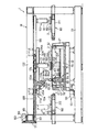
- FIG. 1 is a side view for explaining a preferred embodiment of the present invention.
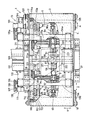
- FIG. 2 is a front explanatory view of the specific example shown in FIG.
- FIG. 3 is a plan explanatory view in which the endless belt, the supporting member and the like are partially broken in the specific example shown in FIG.
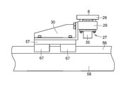
- FIG. 4 is a detailed side view of the glass plate receiving device in the specific example shown in FIG.
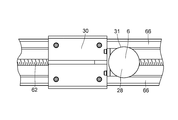
- FIG. 5 is a detailed plan view of the glass plate receiving device in the specific example shown in FIG.
- FIG. 6 is an operation explanatory view of the glass plate receiving device in the specific example shown in FIG.
- FIG. 7 is a detailed explanatory view of the push splitting device in the specific example shown in FIG.
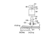
- FIG. 8 is a side view of the pressing body in the specific example shown in FIG. FIG.
- FIG. 9 is an operation explanatory diagram in the specific example shown in FIG.
- FIG. 10 is a cross-sectional view taken along the line XX shown in FIG.
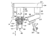
- FIG. 11 is a detailed explanatory view of another preferable specific example of the splitting device in the present invention.
- FIG. 12 is a detailed explanatory view of another preferable specific example of the pressing body according to the present invention.
- FIG. 13 is a cross sectional view taken along the line XII-XII shown in FIG.
- a glass plate breaking machine 1 of the present embodiment is provided with a flexible endless belt 3 as a flexible member on which a glass plate 2 is placed, and a periphery of an upper portion of the endless belt 3.
- a glass plate 2 having a support member 4 for supporting the glass plate 2 from its lower surface side and an upper surface as one surface of the glass plate 2 via an endless belt 3 in an area 5 surrounded by the support member 4.
- a plurality of glass plate receiving devices 7 and 7a each of which has glass plate receiving surfaces 6 and 6a received from the lower surface as a surface and is arranged below the upper portion of the endless belt 3,
- Each of the glass plate receiving devices 7 and 7a is placed in a plane parallel to the surface of the glass plate 2, that is, in the present example, the X direction, which is one direction in the horizontal plane, and the other direction that intersects the X direction, that is, the X direction in this example.
- Moving devices 8 and 8a for moving in the Y direction orthogonal to the direction, and glass 2 are arranged above the upper part of the endless belt 3 and are respectively pushed along the planned dividing line (main cutting line) 221 as a cutting line formed on the upper surface of the glass plate 2.
- Moving devices 10 and 10a for moving the glass plate 2 and the glass plate 2 before breaking into the region 5 and carrying out the glass plate 2 after breaking out of the region 5 and the endless belt 3 A tension applying means 12 for applying a tension to the belt, a traveling device 13 for traveling the endless belt 3 in the A direction in the X direction, and a glass plate 2 having a planned split line 221 formed on the upper surface thereof via the endless belt 3.
- a support mechanism 15 having an upper surface 51 as a surface, and a frame 16.
- each of the glass plate receiving devices 7 and 7a, each of the moving devices 8 and 8a, each of the slitting devices 9 and 9a, and each of the moving devices 10 and 10a are configured in the same manner, respectively Except for the above, only the glass plate receiving device 7, the moving device 8, the splitting device 9 and the moving device 10 will be described, and the corresponding parts will be shown only by adding the same numeral symbol to a.
- the endless belt 3 is wound around the driving drum 17, the driven drum 18, and the free rotating drums 19 and 20.
- the support member 4 made of hollow square bar is supported by the base 23 of the frame 16 via the bracket 21 and the intermediate base 22 of the frame 16.
- the support member 4 may be made of a plate-shaped member instead of the hollow square bar.
- the support member 4 supports the upper side portion of the endless belt 3 from the lower surface side thereof, and the upper side portion of the endless belt 3 droops extremely. Therefore, the support member 4 may be omitted as long as desired tension can be applied to the endless belt 3 so that the upper portion of the endless belt 3 does not droop extremely.
- the drive drum 17 and the driven drum 18 are provided as in this example, the drive drum 17 and the driven drum 18 are caused to function as a part of the support member 4, and the drive drum 17 and the driven drum are driven by the support member 4. A portion extending in parallel with the drum 18 may be omitted.
- the glass plate receiving device 7 raises the glass plate receiving surface 6 in contact with the lower surface of the upper side portion of the endless belt 3 by about 1 mm to 5 mm, and then lowers the glass plate receiving surface 6 to the original position after the raising.
- the elevating means 27 has a piston rod pierced movably through the support member 29 and connected to the movable receiving member 28.
- the cylinder device 35 may be an air cylinder device, or may be a hydraulic cylinder device, and the cylinder device 35 may be movable via a piston rod by its operation. And it is adapted to lift the only member 28.
- the flat glass plate receiving surface 6 having a circular outer contour line 31 and extending parallel to the lower surface of the glass plate 2 supports the upper surface 51 of the supporting mechanism 15 and the supporting member 4 when the elevating means 27 does not raise the flat glass plate receiving surface 6. It is parallel to the upper surface 52 as a surface, and is arranged at the same height as the upper surface 51 and the upper surface 52, and when it is lifted by the elevating means 27, about 1 mm to 5 mm with respect to the upper surface 51 and the upper surface 52. Highly priced.
- the moving device 8 includes an X-direction moving mechanism 55 and a Y-direction moving mechanism 56.
- the X-direction moving mechanism 55 is rotatably supported on the X-direction linear moving base 57 to which the base 30 is attached, the electric motor 59 attached to the lateral member 58, and the bearings 60 and 61 on the lateral member 58.
- the output shaft of the electric motor 59 and the pulleys 63 and 64 and the pulley 63 fixed to one end of the screw shaft 62 so that the rotation of the output shaft of the electric motor 59 is transmitted to the screw shaft 62.
- a belt 65 hung between 64 and 64, a nut (not shown) fixed to the lower surface of the linear movement base 57 by being screwed onto the screw shaft 62, and a pair formed on the lateral member 58.
- Rails 66, and a slider 67 that is slidably fitted to the pair of rails 66 and is attached and fixed to the lower surface of the linear movement base 57.
- the Y-direction moving mechanism 56 has substantially the same configuration as the X-direction moving mechanism 55, and includes a lateral member 58 as a Y-direction linear moving base, a support member 70, a bracket 21 and the like on the intermediate base 22.
- a lateral member 71 fixedly mounted, an electric motor 72 mounted to the lateral member 71, a screw shaft 75 rotatably supported by the lateral member 71 via bearings 73 and 74, and an output of the electric motor 72.
- Mated to Attached to the lower surface of the horizontal member 58 is provided with a slider 80 which is fixed.
- the lateral member 58 When the screw shaft 75 is rotated via the pulleys 76 and 77 and the belt 78 by the rotation of the output rotation shaft of the electric motor 72 due to the operation of the electric motor 72, the lateral member 58 is guided by the pair of rails 79 and linearly moves in the Y direction. By the linear movement of the lateral member 58 in the Y direction, the linear movement base 57 is also linearly moved in the Y direction.
- the slitting device 9 is provided on the upper surface of the glass plate 2 at the time of splitting along the planned split line 221 for the glass plate 2 at each split position with respect to the glass plate 2, for example, at each position of the split positions P1, P2, P3, P4 and P5.
- a pressing body 83 that simultaneously presses a plurality of parts along the planned split line 221, two parts 81 and 82 in the present example, in the vertical direction, that is, the Z direction, and the planned split line 221 for the glass plate 2.
- the axis line orthogonal to the upper surface of the glass plate 2 (rotation axis (Center)
- An electric motor 85 as a rotating means for rotating the pressing body 83 in the R1 direction about the O1
- an air cylinder device 89 and a piston rod 90 of the air cylinder device 89, which are attached via a bearing mechanism 91
- a cutter block 93 having a cutter wheel 92 at its tip, an electric motor 94, a pulley or gear 95 attached to the output rotation shaft of the electric motor 94, and an outer cylinder 96 of an air cylinder device 89 attached via a bracket 97.
- Bearing mechanism 98 a pulley or a gear 99 attached to the bearing mechanism 98, and a span between the gear 95 and the gear 99.
- the base 104 to which the electric motors 85 and 94 and the air cylinder device 89 are attached.
- the pressing body 83 is connected to and fixed to the piston rod 130 of the air cylinder device 84, and has a supporting base 106 having a forked portion, and the forked portion of the supporting base 106 is parallel to the upper surface of the glass plate 2 via a shaft 107. And, at least one, which is rotatably supported in the R3 direction about the rotation axis O2 and O3 extending in the direction orthogonal to the direction along the planned split line 221 in this example, is two in this example.
- the rotary body 108 is provided with the individual rotary bodies 108 and 109, and the rotary body 108 follows the planned split line 221 on the upper surface of the glass plate 2 at the time of pressing and splitting along the planned split line 221 with respect to the glass plate 2 by the pressing body 83.
- the rotary body 108 follows the planned split line 221 on the upper surface of the glass plate 2 at the time of pressing and splitting along the planned split line 221 with respect to the glass plate 2 by the pressing body 83.
- at least one part of the parts 81 and 82 in this example, a circle as a contact surface that rotatably contacts the part 81.
- the rotary body 109 also has a rotatable surface 301, and the rotary body 109 also follows the planned crease line 221 on the upper surface of the glass plate 2 at the time of pressing and splitting along the planned crease line 221 with respect to the glass plate 2 by the pressing body 83.
- a cylindrical rotatable surface 302 as a contact surface that rotatably contacts the portion 82 is provided. There is.
- the rotatable surface 301 is rotated when the pressing body 83 is pressed by a plurality of portions 81 and 82 along the planned breaking line 221 on the upper surface of the glass plate 2 at the time of pressing and breaking along the planned breaking line 221 with respect to the glass plate 2. At least one of each of the plurality of portions 81 and 82, which is the portion 81 in this example, is rotatably in contact with each other about the axis O2, and the rotatable surface 301 is folded over the glass plate 2. At least one part of a plurality of parts 81 and 82 along the planned split line 221 on the upper surface of the glass plate 2 at the time of pressing and splitting along the planned split line 221.
- the part 81 straddles the planned split line 221. It is formed with a width in the direction in which the rotation axis O2 extends so as to press the upper surface of the plate 2, and similarly, the rotatable surface 302 is formed on the glass plate 2.
- each of 81 and 82 is rotatably in contact with at least one of the parts, in this example, the part 82, and the rotatable surface 302 has a foldable surface 302 for the crushing along the planned fold line 221 with respect to the glass plate 2.
- At least one part of the plurality of parts 81 and 82 along the planned split line 221 on the upper surface of the glass plate 2, in this example, the part 82 is configured to press the upper surface of the glass plate 2 across the planned split line 221. , With a width in the extending direction of the rotation axis O3.
- Each of the rotating bodies 108 and 109 comprises a rigid disc and an elastic annular outer surface layer covering the outer peripheral surface of the disc so that the rotatable surfaces 301 and 302 are flexible elastic surfaces. May be.
- the cutter wheel 92 is moved in the Z direction, and the rotation of the gear 95 by the operation of the electric motor 94 causes the gear 99 to move through the chain 100.
- the engaging member 102 and the engaging piece 103 that engages with the engaging member 102 at the slit 101 are also rotated in the R2 direction about the axis (rotational axis) 105, and the cutter wheel 92 is also rotated by this rotation. It is rotated in the R2 direction about the axis 105, and its cutting edge is oriented in the cutting line forming direction.
- the output rotary shaft 131 is connected and fixed to the output rotary shaft 131 by the rotation of the output rotary shaft 131 in the R1 direction due to the operation of the electric motor 85 at each of the split positions P1, P2, P3, P4 and P5.
- the piston rod 130 of the air cylinder device 84 rotates in the R1 direction
- the two rotating bodies 108 and 109 are aligned with the planned split line 221 at the respective positions of the push split positions P1, P2, P3, P4, and P5.
- the rotary bodies 108 and 109 are respectively arranged by the lowering of the pressing body 83 due to the extension of the piston rod 130 by the operation of the air cylinder device 84.
- the moving device 10 includes an X-direction moving mechanism 110 and a Y-direction moving mechanism 111.
- the X-direction moving mechanism 110 includes an X-direction linear moving base 112 to which the base 104 of the splitting device 9 is attached, an electric motor 114 attached to the lateral member 113, and bearings 115 and 116 on the lateral member 113.
- a screw shaft 117 rotatably supported, and a pulley 118 fixed to the output rotary shaft of the electric motor 114 and one end of the screw shaft 117 so as to transmit the rotation of the output rotary shaft of the electric motor 114 to the screw shaft 117.
- a pair of formed rails 121 and a slider 122 that is slidably fitted to the pair of rails 121 and is attached and fixed to the lower surface of the linear movement base 112. It is equipped with.
- the Y-direction moving mechanism 111 is configured almost the same as the X-direction moving mechanism 110, and is fixed to the horizontal member 113 as a Y-direction linear moving base and the upper frame 132 of the frame 16 via the bracket 133 and the like.
- a slider (not shown) fixed to the upper surface of the horizontal member 134 by slidably fitting to the rail 141 of the horizontal member 134.
- the horizontal member 134 includes the slider and the pair of rails 141. It is hung and supported by the horizontal member 134 via the so as to be movable in the Y direction.
- the lateral member 134 is guided by the pair of rails 141 and moves linearly in the Y direction.
- the linear movement base 112 is also linearly moved in the Y direction by the linear movement of the lateral member 134 in the Y direction.
- the carrying-in / carrying-out means 11 lifts the glass plate 2 placed on the endless belt 3 and completed the breaking, and the glass plate 2 placed on the endless belt 3 during the breaking via the endless belt 3.
- a lifting mechanism 151 that clamps in cooperation with the support mechanism 15 and fixes it on the endless belt 3
- a lifting mechanism 152 that places the glass plate 2 to be split on the endless belt 3
- a pair of lifting mechanisms 151 and 152 and a reciprocating mechanism 153 that reciprocates in the Y direction.
- the lifting mechanism 151 includes an air cylinder device 156 attached to the movable base 155 and a vacuum suction device 158 attached to the tip of the piston rod 157 of the air cylinder device 156.
- the vacuum sucker device 158 lifts the glass plate 2 placed on the endless belt 3 and moves the glass plate 2 placed on the endless belt 3 to the endless belt. It is clamped in cooperation with the support mechanism 15 via 3 and fixed on the endless belt 3.
- the lifting mechanism 152 is formed similarly to the lifting mechanism 151, and has an air cylinder device 161 attached to a movable base 155 common to the lifting mechanism 151 and a vacuum attached to the tip of a piston rod 162 of the air cylinder device 161.
- the vacuum suction device 163 places the sucked glass plate 2 on the endless belt 3. Place.
- the reciprocating mechanism 153 includes a movable base 155, an electric motor 166 attached to the upper frame 165 of the frame 16, a screw shaft 168 rotatably supported by the upper frame 132 of the frame 16 via a bearing 167, and an electric motor.
- an electric motor In order to transmit the rotation of the output rotation shaft of the motor 166 to the screw shaft 168, the output rotation shaft of the electric motor 166 and the pulleys 169 and 170 fixed to one end of the screw shaft 168 and the pulleys 169 and 170 are provided.
- the movable base 155 suspended and supported by the upper frame 132 via the slider 174 so as to be movable in the Y direction is rotated by its output rotary shaft by the operation of the electric motor 166, and is screwed through the pulleys 169 and 170 and the belt 171.
- the shaft 168 When the shaft 168 is rotated, it is guided by the pair of rails 173 and linearly reciprocated in the Y direction.
- the carry-in / carry-out means 11 linearly reciprocates the lifting mechanisms 151 and 152 in the Y direction by the operation of the reciprocating mechanism 153, and in this linear reciprocal movement, the lifting mechanism 152 places the lifting mechanism 151 and 152 on the entrance-side transport device 181.
- the glass plate 2 before being broken is lifted up, carried into the region 5 surrounded by the supporting member 4, placed on the upper surface of the upper portion of the endless belt 3, and the lifting mechanism 151 causes the endless belt 3 to move.
- the broken glass plate 2 placed on the upper surface of the upper part of the above is carried out of the region 5 surrounded by the supporting member 4 and placed on the delivery device 182 on the delivery side.
- the tension applying means 12 is provided with a pair of air cylinder devices 185 and 186 supported by the bracket 21, and the piston rod of the air cylinder device 185 rotatably supports the free rotating drum 19.
- the piston rod of the device 186 rotatably supports the free rotating drum 20.
- the tension applying means 12 applies tension to the endless belt 3 via the free rotating drums 19 and 20 by the aeroelastic force of the air cylinder devices 185 and 186, whereby the endless belt 3 is tensioned. There is. If the endless belt 3 can be tensioned as desired by adjusting the positions of the driving drum 17, the driven drum 18, and the free rotating drums 19 and 20, the tension applying means 12 may not be provided.
- the traveling device 13 uses the electric motor 191, which is attached to the base 23, the driving drum 17 and the driven drum 18, the free rotating drums 19 and 20, and the rotation of the output rotating shaft of the electric motor 191, to rotate the rotating shaft of the driving drum 17. And a belt 194 wound around the pulleys 192 and 193 and the pulleys 192 and 193, which are attached to the output rotary shaft of the electric motor 191 and the rotary shaft of the drive drum 17.
- the driven drum 18 is rotatably attached to frames 195 and 196 supported by the intermediate base 22, respectively.
- the traveling device 13 rotates the drive drum 17 via the pulley 192, the belt 194, and the pulley 193, and the rotation of the drive drum 17 causes the endless belt 3 to rotate.
- the endless belt 3 travels in the A direction, and thereby the endless belt 3 conveys the cullet folded on the endless belt 3 in the A direction and discharges the cullet out of the region 5.
- the support mechanism 15 includes a rectangular receiving plate 201 and a supporting column 202 that supports the receiving plate 201, and the supporting column 202 is supported by the bracket 21 via a lateral member 203.
- the support mechanism 15 supports the glass plate 2 mounted on the endless belt 3 from below via the endless belt 3 on the upper surface 51 of the receiving plate 201, and cooperates with the vacuum suction device 158 to support the glass plate 2 accordingly. And is fixed on the endless belt 3.
- the entrance-side transport device 181 includes an endless belt 211 on which the glass plate 2 to be broken is placed, and a traveling device (not shown) that causes the endless belt 211 to travel.
- the plate 2 is accurately carried to a predetermined position by running the endless belt 211 based on the operation of the running device.
- the exit-side transport device 182 includes an endless belt 212 on which the folded glass plate 2 is placed, and a traveling device (not shown) for traveling the endless belt 212.
- the plate 2 is conveyed to the next processing step, for example, the step of grinding and polishing the split edge by traveling the endless belt 212 based on the operation of the traveling device.
- the glass plate breaking machine 1 is additionally provided with a control device including a microcomputer, etc., and the control device pre-programs numerical control commands for operating the electric motor, the air cylinder device, the vacuum suction device, and the like. Control through. Since such a control device itself is known, a detailed description thereof will be omitted.
- the glass plate breaking machine 1 performs the breaking work on the glass plate 2 as follows.
- the glass plate 2 to which the planned split line (main cutting line) 221 is attached in advance as a cutting line is placed at an accurate position by the endless belt 211.
- a planned splitting line 221 is an end cutting line (auxiliary cutting line) equipped with the air cylinder device 89, the cutter block 93, the electric motor 94 and the like in the splitting device 9 in the glass sheet splitting machine 1 of this example. ) It may be formed by a forming mechanism.
- the plate 2 is sucked by the vacuum sucker device 163 to the glass plate 2 to be folded next on the endless belt 211, and then the air cylinder devices 156 and 161 are operated to cause the vacuum sucker device 158 to move the glass plate 2 on the endless belt 3.
- the broken glass plate 2 is lifted by the vacuum suction device 163 on the endless belt 211 to be broken.
- the electric motor 166 of the reciprocating mechanism 153 is operated to move the movable table 155 forward, and the already broken glass plate 2 lifted by the vacuum suction device 158 is outside the area 5 surrounded by the support member 4. Then, the glass plate 2 which is carried out onto the endless belt 212 and lifted up by the vacuum suction device 163 to be broken is carried into the endless belt 3 into the region 5 surrounded by the supporting member 4.
- the electric motor 191 is operated, whereby the endless belt 3 travels in the direction A and remains on the upper side of the endless belt 3.
- the split cullet is conveyed and discharged in the direction A as the endless belt 3 travels.
- the operation of the electric motor 191 is stopped and the traveling of the endless belt 3 in the A direction is stopped.
- the air cylinder devices 156 and 161 are re-activated, the vacuum suction cup devices 158 and 163 are lowered, and after the vacuum suction cup devices 158 and 163 are lowered to a predetermined position, the suction of the vacuum suction cup devices 158 and 163 is performed. The operation is stopped, and the glass plate 2 folded and broken on the endless belt 212 by the vacuum sucker device 158 is placed on the endless belt 3 by the vacuum sucker device 163.
- the air cylinder devices 156 and 161 are reversely actuated to raise the vacuum suction cup devices 158 and 163, and further, the electric motor 166 of the reciprocating mechanism 153 is reversely actuated to return the movable table 155 to the vacuum suction cup.
- the device 163 is moved onto the endless belt 211, and the vacuum suction device 158 is moved onto the endless belt 3.
- the glass plate 2 to be broken next is carried into a predetermined position by the operation of the endless belt 211.
- the air cylinder devices 156 and 161 are reactivated, the vacuum suction cup devices 158 and 163 are lowered, and the vacuum suction cup devices 158 and 163 are moved to the predetermined positions.
- the glass plate 2 placed on the upper side of the endless belt 3 is pressed against the endless belt 3 by the vacuum suction device 158 with aeroelastic force based on the air cylinder device 156, and the air cylinder device 161 is also used.
- the glass plate 2 placed on the endless belt 211 is pressed against the endless belt 211 by the vacuum suction device 163 with aeroelastic force.
- the glass plate 2 placed on the upper side of the endless belt 3 is sandwiched between the vacuum suction device 158 and the receiving plate 201 with the endless belt 3 in between at the central portion thereof, and the endless belt 3 is securely held. It will be held and fixed on the upper part.
- the electric motors 59 and 59a and 72 and 72a are operated to move the glass plate receiving devices 7 and 7a in the X and Y directions so that the glass receiving surfaces 6 and 6a are arranged below the cutter wheels 92 and 92a.
- the electric motors 114 and 114a and 135 and 135a are operated to move the pushing and splitting devices 9 and 9a in the X and Y directions to move the cutter wheels 92 and 92a to one inflection point of the planned split line 221.
- the glass plate 2 is moved toward the outer edge 220 (outer edge of the raw sheet glass).
- the air cylinder devices 89 and 89a are simultaneously actuated to bring the cutter wheels 92 and 92a into contact with the glass plate 2 and thereby the cutter wheels 92 and 92a.
- An edge cutting line (auxiliary cutting line) 222 is formed on the glass plate 2 with 92a.
- the electric motors 94 and 94a are operated so that the cutting edges of the cutter wheels 92 and 92a are directed in the direction of forming the end cutting line.
- the rotating bodies 108 and 109 and the rotating bodies 108a and 109a are raised without the rotatable surfaces 301 and 302 and 301a and 302a contacting the upper surface of the glass plate 2.
- the pushing and splitting devices 9 and 9a and the glass plate receiving devices 7 and 7a are successively connected to the respective starting points of the end cutting line forming positions which are the respective inflection points of the planned splitting line 221.
- the cutter wheels 92 and 92a respectively form the end cutting lines 222 in the area 5.
- the glass plate receiving surfaces 6 and 6a correspond to the movement of the cutter wheels 92 and 92a so as to receive the pressing force of the cutter wheels 92 and 92a via the glass plate 2 and the endless belt 3.
- the plate receiving devices 7 and 7a are moved.
- the air cylinder devices 89 and 89a are then operated to raise the cutter wheels 92 and 92a to release the contact between the cutter wheels 92 and 92a and the glass plate 2.
- the electric motors 59 and 59a are arranged so that the glass plate receiving surfaces 6 and 6a are arranged at positions where the outer contour lines 31 of the glass plate receiving surfaces 6 and 6a are close to the planned split line 221 of the glass plate 2 in plan view. And 72 and 72a to move the glass plate receiving devices 7 and 7a in the X and Y directions, and also activate the electric motors 114 and 114a and 135 and 135a to move the splitting devices 9 and 9a in the X and Y directions. Then, the rotatable surfaces 301 and 302 and 301a and 302a of the rotating bodies 108 and 109 and 108a and 109a are respectively arranged on the planned split line 221. Disposed above the respective sites 81 and 82 I.
- the glass plate receiving surfaces 6 and 6a are actuated to raise the glass plate receiving surfaces 6 and 6a by about 1 mm to 5 mm through the movable receiving members 28 and 28a, and the upward bending from the vicinity of the planned split line 221 of the glass plate 2 as a starting point
- the air cylinder devices 84 and 84a are operated in a state in which the glass plate 2 on the outside is caused to bend and the pressure bodies 83 and 83a are lowered to rotate the rotatable surfaces 301 and 302 as shown in FIG.
- the breaking machine 1 for a glass plate 2 of this example supports a glass plate 2 having a planned splitting line 221 as a cut line on the upper surface, which is one surface, on the lower surface, which is the other surface of the glass plate 2. It is equipped with a supporting mechanism 15 for pushing and breaking, and a splitting device 9 and 9a for splitting the glass plate 2 along the planned split line 221.
- the splitting devices 9 and 9a are split positions P1, P2, P3 with respect to the glass plate 2. , P4 and P5 along the planned split line 221 against the glass plate 2 at the same time, a pressing body 83 for simultaneously pressing a plurality of portions 81 and 82 along the planned split line 221 on the upper surface of the glass plate 2.
- the pressing body 83 simultaneously presses a plurality of parts 81 and 82 along the planned breaking line 221 on the upper surface of the glass plate 2 during the pressing and breaking along the planned breaking line 221 with respect to the glass plate 2.
- the order adapted to press capable of performing bend-breaking position P1, P2, P3, P4 and a stable bend-breaking in each of P5.
- the planned split line 221 may be formed by the splitting devices 9 and 9a of the glass plate splitting machine 1, and in the glass plate splitting machine 1, only splitting is possible.
- the edge cutting line may be formed in the previous step, and in this case, the cutter wheels 92 and 92a and the like can be omitted.
- a pair of glass plate receiving devices 7 and 7a, a pair of moving devices 8 and 8a, a pair of splitting devices 9 and 9a, and a pair of moving devices 10 and 10a are provided, and the end to the glass plate 2 is provided.
- the glass plate receiving device 7 and the slitting device 9 are half of the region 5 in the X direction, and the glass plate receiving device 7a and the slitting device 9a are the rest in the X direction of the region 5.
- only one piece or three or more pieces may be provided to configure the glass plate breaking machine.
- the sharing operation such as the push and split does not have to be performed at the same time, and may be performed at an appropriate interval.
- the pressing body 83 is moved in the Z direction by the expansion and contraction of the piston rod 130 to bring the rotatable surfaces 301 and 302 into contact with the portions 81 and 82 on the upper surface of the glass plate 2, whereby Although the glass plate 2 is pushed and broken, instead of this, as shown in FIG. 11, the suspension member 231 is connected and fixed to the output rotation shaft 131, and the suspension member 231 is operated by the piston rod 130 in the Z-direction.
- the air cylinder device 84 is connected and fixed so as to advance and retreat in an oblique direction S intersecting the direction, and when the rotatable surfaces 301 and 302 come into contact with the portions 81 and 82 of the glass plate 2 when the piston rod 130 extends, the air cylinder device 84 rotates.
- the glass plate 2 is pushed diagonally downward by the free surfaces 301 and 302, and the glass plate 2 outside the area B is separated from the glass plate 2 inside the area B and kicked toward the outer edge 220 of the glass plate 2. As out, thereby, it may be divided down the glass plate 2.
- the pressing body 83 that presses the parts 81 and 82 at the same time has the rotatable surfaces 301 and 302 in the above example, but instead of this, from the partially spherical surface or the partially cylindrical surface that does not rotate. May have a curved convex surface or a flat surface.
- the pressing body 310 that simultaneously presses the portions 81 and 82 is a partial cylindrical surface as a contact surface that does not rotate.
- the pressing body 310 is configured such that, when the glass plate 2 is pushed and split along the planned dividing line 221, each of the planned dividing lines 2 of the curved convex surface 311 is formed. It will simultaneously push the respective parts 81 and 82 located at the bend-scheduled line 221 with along the bend-scheduled line 221 in linear lower end extending 1 and in the same direction.
- the glass plate receiving surfaces 6 and 6a are moved up and down by the elevating means 27 and 27a, but the elevating means 27 and 27a are not provided, and the glass plate receiving surfaces 6 and 6a are always on the upper surface. It may be arranged about 1 mm to 5 mm above 51.
- the cutter wheel 92 is rotated in the R2 direction about the axis 105 by the electric motor 94 as a rotating unit that rotates the pressing body 83 in the R1 direction about the axis (rotational axis) O1.
- the pressing body 83 is rotated in the R1 direction about the axis O1 by the electric motor 85, instead of this, an electric motor common to the rotation of the cutter wheel 92 and the pressing body 83 is attached to the base 104, and A common electric motor may be used to rotate the cutter wheel 92 through the air cylinder device 89 and the pressing body 83 through the air cylinder device 84 in the R2 direction about the axis 105.
- the base 104 is pushed without moving in the X direction and the Y direction, but instead of this, in the push split, for example, the rotatable surfaces 301 and 302 or the curved convex surface 311 is used.
- the glass plate 2 outside the region B is separated from the glass plate 2 in the region B toward the outer edge 220 of the glass plate 2 and rotatable surfaces 301 and 302 or curved convex surfaces.
- the base 104 may be moved by the moving device 10 in a direction orthogonal to the planned split line 221 so as to be pushed out by 311.
Landscapes
- Chemical & Material Sciences (AREA)
- Engineering & Computer Science (AREA)
- Materials Engineering (AREA)
- Organic Chemistry (AREA)
- Mechanical Engineering (AREA)
- Life Sciences & Earth Sciences (AREA)
- Forests & Forestry (AREA)
- Re-Forming, After-Treatment, Cutting And Transporting Of Glass Products (AREA)
- Perforating, Stamping-Out Or Severing By Means Other Than Cutting (AREA)
- Processing Of Stones Or Stones Resemblance Materials (AREA)
- Disintegrating Or Milling (AREA)
Abstract
ガラス板2の折割機械1は、一方の面である上面に切り線としての折割予定線221が形成されたガラス板2を当該ガラス板2の他方の面である下面で支持する支持機構15と、ガラス板2を折割予定線221に沿って押し割る押し割り装置9及び9aとを具備しており、押し割り装置9及び9aは、ガラス板2に対する押し割り位置P1、P2、P3、P4及びP5の夫々でのガラス板2に対する折割予定線221に沿う押し割りに際してガラス板2の上面における折割予定線221に沿った複数の部位81及び82を同時的に押圧する押圧体83を具備している。
Description
本発明は、ガラス板の折割機械に関する。
押し割り装置を、無端ベルト上に載置されたガラス板の面に平行な面内で、当該ガラス板に形成された折割線に沿って移動させる一方、無端ベルトの下方でガラス板受け装置を押し割り装置の移動に対応させて移動させるようにしたガラス板の折割機械は、知られている。
斯かるガラス板の折割機械では、切り線に沿ったガラス板に対する押し割りに際しては、一般に、ガラス板受け装置のガラス板受け面をガラス板の下面に配置し、斯かるガラス板受け面で下面が支持されたガラス板の上面の一の部位に押棒を次々に押し当てて、ガラス板を折割線に沿って折割しているために、押棒によるガラス板の上面の一の部位への各押し当てでは、折割が不安定となり、所望の折割を行い得ない虞が生じる。
本発明は、前記諸点に鑑みてなされたものであり、その目的とするところは、各折割位置で安定な折割を行い得るガラス板の折割機械を提供するところにある。
本発明によるガラス板の折割機械は、一方の面に切り線が形成されたガラス板を当該ガラス板の他方の面で支持する支持機構と、ガラス板を切り線に沿って押し割る押し割り装置とを具備しており、押し割り装置は、ガラス板に対する各押し割り位置でのガラス板に対する切り線に沿う押し割りに際してガラス板の一方の面における切り線に沿った複数の部位を同時的に押圧する押圧体を具備している。
斯かる本発明のガラス板の折割機械によれば、押圧体がガラス板に対する切り線に沿う押し割りに際してガラス板の一方の面における切り線に沿った複数の部位を同時的に押圧するようになっているために、各折割位置で安定な折割を行い得る。
本発明において、好ましい例では、押圧体は、ガラス板に対する切り線に沿う押し割りに際してのガラス板の一方の面における切り線に沿った複数の部位の押圧において当該複数の部位の少なくとも一つの部位に接触する平坦面又は部分球面若しくは部分円筒面からなる湾曲凸面を有しており、他の好ましい例では、押圧体は、少なくとも一つの回転体を具備しており、この回転体は、ガラス板に対する切り線に沿う押し割りに際してのガラス板の一方の面における切り線に沿った複数の部位の押圧において当該複数の部位の少なくとも一つの部位に回転自在に又は回転しないように接触する接触面を有している。
斯かる回転体は、好ましい例では、切り線に沿う方向に対して交差する方向に伸びる回転軸心を有しており、接触面は、ガラス板に対する切り線に沿う押し割りに際してのガラス板の一方の面における切り線に沿った複数の部位の押圧において、当該回転軸心を中心として当該複数の部位の少なくとも一つの部位に回転自在に又は回転しないように接触するようになっている。
本発明において、押圧体は、ガラス板に対する切り線に沿う押し割りに際してのガラス板の一方の面における切り線に沿った複数の部位の少なくとも一つの部位では切り線を跨いでガラス板の一方の面を押圧するようになっていてもよい。
本発明のガラス板の折割機械において、押し割り装置は、ガラス板に対する各押し割り位置で、切り線に沿ったガラス板の複数の部位への同時的な押圧を押圧体に行わせるべく、ガラス板の一方の面に直交する軸線を中心として押圧体を回転させる回転手段を更に具備していても、ガラス板に対する切り線に沿う押し割りに際してのガラス板の一方の面における切り線に沿った複数の部位への押圧体による同時的な押圧に必要な押圧力を当該押圧体に与える押圧力付与手段を更に具備していてもよい。
本発明のガラス板の折割機械は、切り線が形成されたガラス板が載置される可撓性部材と、当該可撓性部材を介してガラス板を当該ガラス板の他方の面から受けるガラス板受け面を有しているガラス板受け装置と、このガラス板受け装置を移動させる第一の移動装置と、押し割り装置を移動させる第二の移動装置とを具備していてもよく、この場合、支持機構は、好ましくは、可撓性部材を介してガラス板を当該ガラス板の他方の面で支持する支持面を有している。
本発明による好ましい例では、ガラス板受け装置は、ガラス板受け面を昇降させる昇降手段を具備しており、ガラス板受け面は、押圧体によるガラス板の切り線に沿う押し割りに拘わらず、常時、支持機構の支持面よりも上方に配されていてもよいのであるが、斯かる昇降手段を具備していると、ガラス板の切り線に沿っての押し割りにおいて、ガラス板に予め撓みを生じさせることができる結果、押し割り装置の押圧体によるガラス板の切り線に沿っての押し割りを更に確実に行い得る上に、ガラス板受け面の可撓性部材への不必要な押圧を回避でき、可撓性部材の損傷を低減でき、この場合、ガラス板受け面の支持機構の支持面よりも上方に配される量又は昇降手段による昇降量は、ガラス板の大きさ、厚み、折り割り幅(カレット幅)等により決定され、好ましい例では、1mmから5mm程度であるが、これに限定されない。
本発明において、好ましい例では、第一の移動装置は、ガラス板の面に平行な面内で、ガラス板受け面を一の方向とこの一の方向に交差する他の方向とに移動させる移動機構を具備しており、第二の移動装置は、ガラス板の面に平行な面内で、押圧体を一の方向とこの一の方向に交差する他の方向とに移動させる移動機構を具備している。
本発明の更に他の好ましい例では、可撓性部材は、無端ベルトを具備しており、ガラス板の折割機械は、無端ベルトに張力を与える張力付与手段及び無端ベルトを走行させる走行手段を具備している。
本発明において、ガラス板受け面は、好ましい例では、可撓性部材を介してガラス板の下面を受ける平坦面を具備しているが、斯かる平坦面は、外形が円形、楕円形又は三角形以上の多角形であってもよく、一方、ガラス板受け面は、斯かる平坦面に代えて、部分円錐凸面及び部分円球凸面を含む凸面を具備していてもよい。
本発明の折割機械によって折割されるガラス板としては、一般の建造物の窓用のガラス板、家具用のガラス板及び例えばフロントガラス、リアーガラス若しくはサイドガラス等の自動車用のガラス板並びにコンピュータ及び携帯電話機等の表示画面用のガラス板を例示することができるが、その他のガラス板をも含み得る。
本発明における可撓性部材としては、可撓性の無端部材である可撓性の無端ベルトを好ましい例として挙げることができるが、その他、可撓性の有端シートであってもよい。
本発明によれば、各折割位置で安定な折割を行い得るガラス板の折割機械を提供することができる。
以下、本発明を図面に示す具体例に基づいて更に詳細に説明する。これにより前記発明及び更に他の発明が明瞭となるであろう。尚、本発明はこれら具体例に何等限定されないのである。
図1から図8において、本例のガラス板の折割機械1は、ガラス板2が載置される可撓性部材としての可撓性の無端ベルト3と、無端ベルト3の上側部の周囲を、その下面側から支持する支持部材4と、一方の面としての上面を有したガラス板2を、支持部材4により囲まれた領域5内において無端ベルト3を介してガラス板2の他方の面としての下面から受けるガラス板受け面6及び6aの夫々を有していると共に無端ベルト3の上側部の下方に配された複数、本例では2機のガラス板受け装置7及び7aと、ガラス板受け装置7及び7aの夫々を、ガラス板2の面に平行な面内、本例では水平面内での一の方向であるX方向とX方向に交差する他の方向、本例ではX方向と直交するY方向とに移動させる移動装置8及び8aと、ガラス板2を当該ガラス板2の上面に形成された切り線としての折割予定線(主切り線)221に沿って夫々が押し割ると共に無端ベルト3の上側部の上方に配された複数、本例では2機の押し割り装置9及び9aと、押し割り装置9及び9aの夫々を、水平面内で一の方向であるX方向とX方向に交差する他の方向、本例ではX方向と直交するY方向とに移動させる移動装置10及び10aと、折割り前のガラス板2を領域5内に搬入し、折割り後のガラス板2を領域5外に搬出する搬入、搬出手段11と、無端ベルト3に張力を与える張力付与手段12と、無端ベルト3をX方向においてA方向に走行させる走行装置13と、上面に折割予定線221が形成されたガラス板2を無端ベルト3を介して当該ガラス板2の下面の中央部で支持する支持面としての上面51を有した支持機構15と、フレーム16とを具備している。
ガラス板受け装置7及び7aの夫々、移動装置8及び8aの夫々、押し割り装置9及び9aの夫々並びに移動装置10及び10aの夫々は、夫々同一に構成されているので、以下では特に必要な場合を除いて、ガラス板受け装置7、移動装置8、押し割り装置9及び移動装置10についてのみ説明し、対応するものには同じ数字符号にaを付して図示のみする。
無端ベルト3は、駆動ドラム17及び従動ドラム18並びに自由回転ドラム19及び20に掛け回されている。
中空角材からなる支持部材4は、フレーム16のブラケット21及び中間基台22を介してフレーム16の基台23に支持されている。支持部材4は、中空角材に代えて、板状部材からなっていてもよく、要は、無端ベルト3の上側部をその下面側から支持して、無端ベルト3の上側部が極端に垂れ下がらないようにできればよく、したがって、無端ベルト3に所望に張力を付与できて、無端ベルト3の上側部が極端に垂れ下がらないようにできれば、支持部材4を省いてもよい。また、本例のように、駆動ドラム17及び従動ドラム18が設けられる場合には、駆動ドラム17及び従動ドラム18を支持部材4の一部として機能させて、支持部材4において駆動ドラム17及び従動ドラム18と平行に伸びる部位を省いてもよい。
ガラス板受け装置7は、無端ベルト3の上側部の下面に接触しているガラス板受け面6を1mmから5mm程度上昇させる一方、当該上昇後、ガラス板受け面6を元の位置に下降させるガラス板受け面6の昇降手段27と、ガラス板受け面6が一端面に形成されている可動受け部材28と、可動受け部材28が上下方向に移動自在に取付けられた支持部材29と、支持部材29が取付けられた基台30とを具備しており、昇降手段27は、支持部材29を移動自在に貫通していると共に可動受け部材28に連結されたピストンロッドを有して支持部材29に取付けられたシリンダ装置35を具備しており、シリンダ装置35は、エアシリンダ装置からなってもよいが、油圧シリンダ装置でもよく、その作動で、ピストンロッドを介して可動受け部材28を昇降させるようになっている。
円形の外側輪郭線31を有すると共にガラス板2の下面に平行に伸びた平坦なガラス板受け面6は、昇降手段27により上昇されない場合には、支持機構15の上面51及び支持部材4の支持面としての上面52と平行であって、当該上面51及び上面52と同一高さに配されており、昇降手段27により上昇された場合には、上面51及び上面52に対して1mmから5mm程度高く配されている。
移動装置8は、X方向移動機構55とY方向移動機構56とからなる。
X方向移動機構55は、基台30が取付けられたX方向の直線移動台57と、横部材58に取付けられた電動モータ59と、横部材58に軸受60及び61を介して回転自在に支持されたねじ軸62と、電動モータ59の出力回転軸の回転をねじ軸62に伝達するように、電動モータ59の出力回転軸及びねじ軸62の一端に固着されたプーリ63及び64並びにプーリ63及び64間に掛け渡されたベルト65と、ねじ軸62に螺合して、直線移動台57の下面に取付けられて固着されたナット(図示せず)と、横部材58に形成された一対のレール66と、一対のレール66に摺動自在に嵌合して、直線移動台57の下面に取付けられて固着されたスライダ67とを具備している。
直線移動台57は、電動モータ59の作動によるその出力回転軸の回転でプーリ63及び64並びにベルト65を介してねじ軸62が回転されると、一対のレール66に案内されてX方向に直線移動されるようになっている。
Y方向移動機構56は、X方向移動機構55とほぼ同様に構成されており、Y方向の直線移動台としての横部材58と、中間基台22上に支持部材70及びブラケット21等を介して固定して取付けられた横部材71と、横部材71に取付けられた電動モータ72と、横部材71に軸受73及び74を介して回転自在に支持されたねじ軸75と、電動モータ72の出力回転軸の回転をねじ軸75に伝達するように、電動モータ72の出力回転軸及びねじ軸75の一端に固着されたプーリ76及び77並びにプーリ76及び77間に掛け渡されたベルト78と、ねじ軸75に螺合して、横部材58の下面に取付けられて固着されたナット(図示せず)と、横部材71に形成された一対のレール79と、一対のレール79に摺動自在に嵌合して、横部材58の下面に取付けられて固着されたスライダ80とを具備している。
横部材58は、電動モータ72の作動によるその出力回転軸の回転でプーリ76及び77並びにベルト78を介してねじ軸75が回転されると、一対のレール79に案内されてY方向に直線移動されるようになっており、而して、横部材58のY方向の直線移動により、直線移動台57は、同じく、Y方向に直線移動されるようになっている。
押し割り装置9は、ガラス板2に対する各押し割り位置、例えば押し割り位置P1、P2、P3、P4及びP5の夫々の位置でのガラス板2に対する折割予定線221に沿う押し割りに際してガラス板2の上面における折割予定線221に沿った複数の部位、本例では二つの部位81及び82を上下方向、即ちZ方向において同時的に下方に押圧する押圧体83と、ガラス板2に対する折割予定線221に沿う押し割りに際してのガラス板2の上面における折割予定線221に沿った二つの部位81及び82への押圧体83による同時的な押圧に必要なガラス板2の上面に向かう下方向の押圧力Fを押圧体83に与える押圧力付与手段としてのエアーシリンダ装置84と、ガラス板2に対する押し割り位置P1、P2、P3、P4及びP5の夫々の位置で、折割予定線221に沿ったガラス板2の複数の部位81及び82への同時的な押圧を押圧体83に行わせるべく、ガラス板2の上面に直交する軸線(回転軸心)O1を中心として押圧体83をR1方向に回転させる回転手段としての電動モータ85と、エアーシリンダ装置89と、エアーシリンダ装置89のピストンロッド90にベアリング機構91を介して取付けられており、先端にカッタホイール92を有したカッタブロック93と、電動モータ94と、電動モータ94の出力回転軸に取付けられたプーリ又は歯車95と、エアーシリンダ装置89の外筒96にブラケット97を介して取付けられたベアリング機構98と、ベアリング機構98に取付けられたプーリ又は歯車99と、歯車95と歯車99との間に掛け渡されたタイミングベルト又はチェーン100と、歯車99に取付けられていると共にスリット101が形成された係合部材102と、一端部がスリット101に配されていると共に他端部がカッタブロック93に取付けられた係合片103と、電動モータ85及び94並びにエアーシリンダ装置89が取付けられた基台104とを具備している。
押圧体83は、エアーシリンダ装置84のピストンロッド130に連結、固定されていると共に二股部を有した支持台106と、支持台106の二股部に軸107を介してガラス板2の上面に平行であって折割予定線221に沿う方向に対して交差、本例では直交する方向に伸びる回転軸心O2及びO3を中心としてR3方向に回転自在に支持された少なくとも一つ、本例では二個の回転体108及び109とを具備しており、回転体108は、押圧体83によるガラス板2に対する折割予定線221に沿う押し割りに際してのガラス板2の上面における折割予定線221に沿った複数の部位81及び82の同時的な押圧において複数の部位81及び82の少なくとも一つの部位、本例では部位81に回転自在に接触する接触面としての円筒状の回転自在面301を有しており、回転体109もまた、押圧体83によるガラス板2に対する折割予定線221に沿う押し割りに際してのガラス板2の上面における折割予定線221に沿った複数の部位81及び82の同時的な押圧において複数の部位81及び82の少なくとも一つの部位、本例では部位82に回転自在に接触する接触面としての円筒状の回転自在面302を有している。
回転自在面301は、ガラス板2に対する折割予定線221に沿う押し割りに際してのガラス板2の上面における折割予定線221に沿った複数の部位81及び82での押圧体83の押圧において、回転軸心O2を中心として複数の部位81及び82の夫々の少なくとも一つの部位、本例では部位81に回転自在に接触するようになっており、しかも、回転自在面301は、ガラス板2に対する折割予定線221に沿う押し割りに際してのガラス板2の上面における折割予定線221に沿った複数の部位81及び82の少なくとも一つの部位、本例では部位81では折割予定線221を跨いでガラス板2の上面を押圧するように、回転軸心O2の伸びる方向において幅をもって形成されており、同じく、回転自在面302は、ガラス板2に対する折割予定線221に沿う押し割りに際してのガラス板2の上面における折割予定線221に沿った複数の部位81及び82での押圧体83の押圧において、回転軸心O3を中心として複数の部位81及び82の夫々の少なくとも一つの部位、本例では部位82に回転自在に接触するようになっており、しかも、回転自在面302は、ガラス板2に対する折割予定線221に沿う押し割りに際してのガラス板2の上面における折割予定線221に沿った複数の部位81及び82の少なくとも一つの部位、本例では部位82では折割予定線221を跨いでガラス板2の上面を押圧するように、回転軸心O3の伸びる方向において幅をもって形成されている。
回転体108及び109の夫々は、回転自在面301及び302が可撓性弾性面となるように、剛性の円板と、この円板の外周面を被覆した弾性の環状の外面層とからなっていてもよい。
押し割り装置9では、エアーシリンダ装置89の作動でピストンロッド90が伸縮されると、カッタホイール92はZ方向に移動され、電動モータ94の作動による歯車95の回転でチェーン100を介して歯車99が回転されると、係合部材102及び係合部材102にスリット101で係合する係合片103も軸線(回転軸心)105を中心としてR2方向に回転され、この回転でカッタホイール92は同じく軸線105を中心としてR2方向に回転され、その刃先が切り線形成方向に向けられる。
また、押し割り装置9では、押し割り位置P1、P2、P3、P4及びP5の夫々の位置での電動モータ85の作動によるその出力回転軸131のR1方向の回転による出力回転軸131に連結、固定されたエアーシリンダ装置84におけるそのピストンロッド130の同じくR1方向の回転で、二個の回転体108及び109が押し割り位置P1、P2、P3、P4及びP5の夫々の位置での折割予定線221に沿う方向に配列され、回転体108及び109のこの配列後、エアーシリンダ装置84の作動によるそのピストンロッド130の伸長による押圧体83の下降で回転体108及び109の夫々の回転自在面301及び302が部位81及び82の夫々でのガラス板2の上面を押圧力Fをもって押圧してガラス板受け面6との協働で折割予定線221に沿ってのガラス板2に対する折割予定線221での押し割りを行うようになっている。
移動装置10は、X方向移動機構110とY方向移動機構111とからなる。
X方向移動機構110は、押し割り装置9の基台104が取付けられたX方向の直線移動台112と、横部材113に取付けられた電動モータ114と、横部材113に軸受115及び116を介して回転自在に支持されたねじ軸117と、電動モータ114の出力回転軸の回転をねじ軸117に伝達するように、電動モータ114の出力回転軸及びねじ軸117の一端に固着されたプーリ118及び119並びにプーリ118及び119間に掛け渡されたベルト120と、ねじ軸117に螺合して、直線移動台112の下面に取付けられて固着されたナット(図示せず)と、横部材113に形成された一対のレール121と、一対のレール121に摺動自在に嵌合して、直線移動台112の下面に取付けられて固着されたスライダ122とを具備している。
直線移動台112は、電動モータ114の作動によるその出力回転軸の回転でプーリ118及び119並びにベルト120を介してねじ軸117が回転されると、一対のレール121に案内されてX方向に直線移動されるようになっている。
Y方向移動機構111は、X方向移動機構110とほぼ同様に構成されており、Y方向の直線移動台としての横部材113と、フレーム16の上枠132にブラケット133等を介して固定して取付けられた横部材134と、横部材134に取付けられた電動モータ135と、横部材134に軸受(図示せず)を介して回転自在に支持されたねじ軸136と、電動モータ135の出力回転軸の回転をねじ軸136に伝達するように、電動モータ135の出力回転軸及びねじ軸136の一端に固着されたプーリ137及び138並びにプーリ137及び138間に掛け渡されたベルト139と、ねじ軸136に螺合して、横部材113の上面に取付けられて固着されたナット140と、横部材134に取付けられた一対のレール141と、一対のレール141に摺動自在に嵌合して、横部材134の上面に取付けられて固着されたスライダ(図示せず)とを具備しており、横部材134は、当該スライダ及び一対のレール141を介して横部材134にY方向に移動自在に吊り下げ支持されている。
横部材134は、電動モータ135の作動によるその出力回転軸の回転でプーリ137及び138並びにベルト139を介してねじ軸136が回転されると、一対のレール141に案内されてY方向に直線移動されるようになっており、而して、横部材134のY方向の直線移動により、直線移動台112は、同じく、Y方向に直線移動されるようになっている。
搬入、搬出手段11は、無端ベルト3上に載置されて折割が完了したガラス板2を持上げ、折割中に無端ベルト3上に載置されたガラス板2を無端ベルト3を介して支持機構15と協同して挟持して無端ベルト3上に固定する持上げ機構151と、無端ベルト3上に折割りすべきガラス板2を載置する持上げ機構152と、一対の持上げ機構151及び152をY方向に往復動させる往復動機構153とを具備している。
持上げ機構151は、可動台155に取付けられたエアーシリンダ装置156と、エアーシリンダ装置156のピストンロッド157の先端に取付けられた真空吸盤装置158とを具備しており、エアーシリンダ装置156の作動でそのピストンロッド157がZ方向に進退されると、真空吸盤装置158は、無端ベルト3上に載置されたガラス板2を持上げ、また無端ベルト3上に載置されたガラス板2を無端ベルト3を介して支持機構15と協同して挟持して無端ベルト3上に固定する。
持上げ機構152は、持上げ機構151と同様に形成されており、持上げ機構151と共通の可動台155に取付けられたエアーシリンダ装置161と、エアーシリンダ装置161のピストンロッド162の先端に取付けられた真空吸盤装置163とを具備しており、エアーシリンダ装置161の作動でそのピストンロッド162がZ方向に下降されると、真空吸盤装置163は、吸引しているガラス板2を無端ベルト3上に載置する。
往復動機構153は、可動台155と、フレーム16の上枠165に取付けられた電動モータ166と、フレーム16の上枠132に軸受167を介して回転自在に支持されたねじ軸168と、電動モータ166の出力回転軸の回転をねじ軸168に伝達するように、電動モータ166の出力回転軸及びねじ軸168の一端に固着されたプーリ169及び170並びにプーリ169及び170間に掛け渡されたベルト171と、ねじ軸168に螺合して、可動台155の上面に取付けられて固着されたナット172と、上枠132に形成された一対のレール173と、一対のレール173に摺動自在に嵌合して、可動台155の上面に取付けられて固着されたスライダ174とを具備している。
スライダ174を介して上枠132にY方向に移動自在に吊り下げ支持されている可動台155は、電動モータ166の作動によるその出力回転軸の回転でプーリ169及び170並びにベルト171を介してねじ軸168が回転されると、一対のレール173に案内されてY方向に直線往復移動されるようになっている。
搬入、搬出手段11は、往復動機構153の作動により持上げ機構151及び152をY方向に直線往復移動させ、この直線往復移動において、持上げ機構152により、入り側の搬送装置181に載置されている折割り前のガラス板2を持ち上げて、これを支持部材4に囲まれた領域5内に搬入して、無端ベルト3の上側部の上面に載置し、持上げ機構151により、無端ベルト3の上側部の上面に載置された折割り後のガラス板2を支持部材4に囲まれた領域5外に搬出して、これを出側の搬送装置182に載置する。
張力付与手段12は、ブラケット21に支持された一対のエアーシリンダ装置185及び186を具備しており、エアーシリンダ装置185のピストンロッドは、自由回転ドラム19を回転自在に支持しており、エアーシリンダ装置186のピストンロッドは、自由回転ドラム20を回転自在に支持している。
張力付与手段12は、エアーシリンダ装置185及び186の空気弾性力により自由回転ドラム19及び20を介して無端ベルト3に張力を付与しており、これにより無端ベルト3が緊張されるようになっている。駆動ドラム17、従動ドラム18、自由回転ドラム19及び20の位置調整により無端ベルト3を所望に緊張させることができる場合には、張力付与手段12を設けなくてもよい。
走行装置13は、基台23に取付けられた電動モータ191と、駆動ドラム17及び従動ドラム18と、自由回転ドラム19及び20と、電動モータ191の出力回転軸の回転を駆動ドラム17の回転軸に伝達するように、電動モータ191の出力回転軸及び駆動ドラム17の回転軸に取付けられたプーリ192及び193並びにプーリ192及び193に掛け回されたベルト194とを具備しており、駆動ドラム17及び従動ドラム18は夫々、中間基台22に支持されたフレーム195及び196に回転自在に取付けられている。
走行装置13は、電動モータ191が作動されてその出力回転軸が回転されると、プーリ192、ベルト194、プーリ193を介して駆動ドラム17を回転させ、駆動ドラム17の回転で無端ベルト3は例えばA方向に走行され、これにより無端ベルト3は、無端ベルト3上で折り割られたカレットをA方向に搬送して当該カレットを領域5外に排出する。
支持機構15は、矩形状の受け板201と、受け板201を支持する支柱202とを具備しており、支柱202は、横部材203を介してブラケット21に支持されている。
支持機構15は、受け板201の上面51で無端ベルト3を介して、当該無端ベルト3上に載置されたガラス板2を下から支持すると共に真空吸盤装置158と協同して当該ガラス板2を挟持してこれを無端ベルト3上に固定する。
入り側の搬送装置181は、折割すべきガラス板2が載置される無端ベルト211と、無端ベルト211を走行させる走行装置(図示せず)とを具備しており、折割すべきガラス板2を、走行装置の作動に基づく無端ベルト211の走行により所定位置まで正確に搬入する。
出側の搬送装置182は、折り割られたガラス板2が載置される無端ベルト212と、無端ベルト212を走行させる走行装置(図示せず)とを具備しており、折り割られたガラス板2を、走行装置の作動に基づく無端ベルト212の走行により次の処理工程、例えば折割縁を研削、研磨する工程に搬送する。
ガラス板の折割機械1は、その他にマイクロコンピュータ等からなる制御装置を具備しており、制御装置は、電動モータ並びにエアーシリンダ装置並びに真空吸引装置等の作動を、予めプログラムされた数値制御命令を介して制御する。このような制御装置自体は公知であるので、それの詳細な説明は省略する。
ガラス板の折割機械1は、次のようにしてガラス板2に対して折割作業を行う。
まず、切り線として予め折割予定線(主切り線)221が付されたガラス板2が無端ベルト211により正確な位置に配される。尚、このような折割予定線221は本例のガラス板の折割機械1における押し割り装置9でのエアーシリンダ装置89、カッタブロック93及び電動モータ94等を具備した端切り線(補助切り線)形成機構によって形成するようにしてもよい。
一つの折割完了において、エアーシリンダ装置156及び161の作動により既に下降されている真空吸盤装置158及び163の夫々を作動させて、真空吸盤装置158により無端ベルト3上のすでに折割されたガラス板2を、真空吸盤装置163により無端ベルト211上の次に折り割るべきガラス板2を夫々吸引して、その後、エアーシリンダ装置156及び161を作動させて、真空吸盤装置158により無端ベルト3上の折割されたガラス板2を、真空吸盤装置163により無端ベルト211上の折り割るべきガラス板2を持ち上げる。
持ち上げ後、往復動機構153の電動モータ166を作動させて可動台155を往動させ、真空吸盤装置158により持ち上げられた既に折割されたガラス板2を支持部材4により囲まれた領域5外であって、無端ベルト212上に搬出し、真空吸盤装置163に持ち上げられたこれから折り割るべきガラス板2を無端ベルト3上であって支持部材4により囲まれた領域5内に搬入する。
この搬出、搬入動作中において、ガラス板2が持上げられた状態で、電動モータ191が作動され、これにより無端ベルト3がA方向に走行されると、無端ベルト3の上側部上に残っている折割カレットが無端ベルト3の走行と共にA方向に搬送されて排出される。折割カレットの排出後、電動モータ191の作動が停止されて、無端ベルト3のA方向の走行が停止される。
搬出、搬入後、エアーシリンダ装置156及び161を再作動させて、真空吸盤装置158及び163を下降させて、真空吸盤装置158及び163の所定位置への下降後、真空吸盤装置158及び163の吸引動作を停止させて、真空吸盤装置158により無端ベルト212上に折割されたガラス板2を、真空吸盤装置163により無端ベルト3上にこれから折り割るべきガラス板2を載置する。その後、エアーシリンダ装置156及び161を逆作動させて、真空吸盤装置158及び163を上昇させて、更に、往復動機構153の電動モータ166を逆作動させて可動台155を復動させ、真空吸盤装置163を無端ベルト211上に、真空吸盤装置158を無端ベルト3上に移動させる。
真空吸盤装置158及び163の往復動中に、無端ベルト211の作動により、次に折割されるべきガラス板2が所定位置に搬入される。
真空吸盤装置158及び163が元の位置に復帰されると、エアーシリンダ装置156及び161を再作動させて、真空吸盤装置158及び163を下降させて、真空吸盤装置158及び163の所定位置への下降により、エアーシリンダ装置156に基づく空気弾性力をもって真空吸盤装置158により無端ベルト3の上側部上に載置されたガラス板2を当該無端ベルト3に押圧して、同じくエアーシリンダ装置161に基づく空気弾性力をもって真空吸盤装置163により無端ベルト211上に載置されたガラス板2を当該無端ベルト211に押圧する。
これにより無端ベルト3上の上側部に載置されたガラス板2は、その中央部で無端ベルト3を間にして真空吸盤装置158と受け板201とに挟持されて、しっかりと無端ベルト3の上側部上に保持、固定されることになる。
その後、電動モータ59及び59a並びに72及び72aを作動させてガラス板受け装置7及び7aをX及びY方向に移動させてガラス受け面6及び6aがカッタホイール92及び92aの下に配置されるようにすると共に、電動モータ114及び114a並びに135及び135aを作動させて押し割り装置9及び9aをX及びY方向に移動させてカッタホイール92及び92aを、折割予定線221の一つの変曲点を始点としてガラス板2の外縁220(素板ガラスの外縁)に向って移動させる。カッタホイール92及び92aが折割予定線221の変曲点から移動する際に同時にエアーシリンダ装置89及び89aを作動させてカッタホイール92及び92aをガラス板2に接触させ、これによりカッタホイール92及び92aでもってガラス板2に端切り線(補助切り線)222を形成する。
端切り線222の形成中は、端切り線形成方向にカッタホイール92及び92aの刃先を向けるべく、電動モータ94及び94aを作動させる。また端切り線形成中は、回転体108及び109並びに回転体108a及び109aは、回転自在面301及び302並びに301a及び302aの夫々がガラス板2の上面に接触することなく、上昇されている。
こうして一つの端切り線222が形成されると、押し割り装置9及び9a並びにガラス板受け装置7及び7aは折割予定線221の各変曲点である端切り線形成位置の各始点まで次々に移動され、各始点への移動後、カッタホイール92及び92aは領域5内で各端切り線222の形成を夫々行う。端切り線形成中には、ガラス板受け面6及び6aがカッタホイール92及び92aの押圧力をガラス板2及び無端ベルト3を介して受けるようにカッタホイール92及び92aの移動に対応してガラス板受け装置7及び7aは移動される。
端切り線形成が終了すると、次にエアーシリンダ装置89及び89aを作動させてカッタホイール92及び92aを上昇させてカッタホイール92及び92aとガラス板2との接触を解除する。
そして、図9及び図10に示すように、押し割り位置P1、P2、P3、P4及びP5の夫々の位置で、ガラス板2の切り線である折割予定線221で囲まれる領域B外の位置であって平面視でガラス板受け面6及び6aの外側輪郭線31がガラス板2の折割予定線221に近接する位置にガラス板受け面6及び6aを配置するように電動モータ59及び59a並びに72及び72aを作動させてガラス板受け装置7及び7aをX及びY方向に移動させると共に同じく電動モータ114及び114a並びに135及び135aを作動させて押し割り装置9及び9aをX及びY方向に移動させて、回転体108及び109並びに108a及び109aの回転自在面301及び302並びに301a及び302aの夫々を折割予定線221上であって部位81及び82の夫々の上方に配置する。
回転自在面301及び302並びに301a及び302aの夫々の下端と折割予定線221での部位81及び82とが夫々Z方向において対峙した状態で、図6に示すように、シリンダ装置35及び35aを作動させ、可動受け部材28及び28aを介してガラス板受け面6及び6aを1mmから5mm程度上昇させ、ガラス板2の折割予定線221の近傍を起点とした上方に向かった撓みを領域B外のガラス板2に生じさせ、斯かる撓みを生じさせた状態で、エアーシリンダ装置84及び84aを作動させて図10に示すように押圧体83及び83aを下降させて回転自在面301及び302並びに301a及び302aの夫々を押し割り位置P1、P2、P3、P4及びP5の夫々の位置でのガラス板2の上面の部位81及び82に接触させて、ガラス板2を各折割予定線221に沿って押し割り、領域B外のガラス板2であって端切り線222間のガラス板2を領域B内のガラス板2から押し割り、押し割り後のシリンダ装置35及び35aの逆作動によるガラス板受け面6及び6aの下降とシリンダ装置84及び84aの逆作動による押圧体83及び83aの上昇とでガラス板受け面6及び6a並びに回転自在面301及び302並びに301a及び302aを元の位置へ復帰させ、この復帰後、領域B外のガラス板2を折割カレットとして無端ベルト3のA方向の走行で排出する。
以上の押し割りが終了して、折割予定線221に沿って折り割られたガラス板2が得られると、以上の動作が繰り返される。
本例のガラス板2の折割機械1は、一方の面である上面に切り線としての折割予定線221が形成されたガラス板2を当該ガラス板2の他方の面である下面で支持する支持機構15と、ガラス板2を折割予定線221に沿って押し割る押し割り装置9及び9aとを具備しており、押し割り装置9及び9aは、ガラス板2に対する押し割り位置P1、P2、P3、P4及びP5の夫々でのガラス板2に対する折割予定線221に沿う押し割りに際してガラス板2の上面における折割予定線221に沿った複数の部位81及び82を同時的に押圧する押圧体83を具備している結果、押圧体83がガラス板2に対する折割予定線221に沿う押し割りに際してガラス板2の上面における折割予定線221に沿った複数の部位81及び82を同時的に押圧するようになっているために、折割位置P1、P2、P3、P4及びP5の夫々で安定な折割を行い得る。
なお、ガラス板の折割機械1の押し割り装置9及び9aによって、端切り線形成に加えて、折割予定線221を形成してもよく、また、ガラス板の折割機械1では、押し割りのみを行うようにし、端切り線形成を前工程で行ってもよく、この場合には、カッタホイール92及び92a等を省くことができる。
更に、上記の具体例では、一対のガラス板受け装置7及び7a、一対の移動装置8及び8a、一対の押し割り装置9及び9a並びに一対の移動装置10及び10aを設けて、ガラス板2に対する端切り線形成及び押し割りを分担、例えば、ガラス板受け装置7及び押し割り装置9は、領域5のX方向における半分の領域を、ガラス板受け装置7a及び押し割り装置9aは、領域5のX方向の残りの半分の領域を分担して行うようにしたが、これに代えて、夫々を一個だけ設けて又は3個以上設けてガラス板の折割機械を構成してもよく、また、端切り線形成及び押し割りの斯かる分担動作は、同時的に行われる必要はなく、適宜必要な間隔をもって行われてもよい。
更に、上記の具体例では、ピストンロッド130の伸縮で押圧体83をZ方向に移動させて、回転自在面301及び302をガラス板2の上面の部位81及び82に接触させて、これにより、ガラス板2を押し割っているが、これに代えて、図11に示すように、出力回転軸131に吊下げ部材231を連結、固定し、吊下げ部材231に、作動においてピストンロッド130がZ方向に交差する斜め方向Sに進退するようにエアーシリンダ装置84を連結、固定し、ピストンロッド130の伸長でのガラス板2の部位81及び82への回転自在面301及び302の接触で、回転自在面301及び302でガラス板2を斜め下方に押すと共に領域B外のガラス板2を領域B内のガラス板2から離してガラス板2の外縁220に向かって蹴り出すようにして、これにより、ガラス板2を押し割るようにしてもよい。
加えて、部位81及び82を同時的に押圧する押圧体83は、上記の例では、回転自在面301及び302を有しているが、これに代えて、回転しない部分球面若しくは部分円筒面からなる湾曲凸面又は平坦面を有していてもよく、例えば、図12及び図13に示すように、部位81及び82を同時的に押圧する押圧体310は、回転しない接触面としての部分円筒面からなる湾曲凸面311を夫々の下端に有した一対の棒状体312及び313と、一対の棒状体312及び313が取付けられていると共にエアーシリンダ装置84のピストンロッド130に連結、固定された基台314とを具備していてもよく、斯かる押圧体310は、折割予定線221に沿ってのガラス板2の押し割りの際には、湾曲凸面311の夫々の折割予定線221と同方向に伸びた線状の下端で折割予定線221に沿うと共に折割予定線221に位置した部位81及び82の夫々を同時的に押圧することになる。
また、上記の具体例では、昇降手段27及び27aでガラス板受け面6及び6aの夫々を昇降させたが、昇降手段27及び27aを設けないで、常時、ガラス板受け面6及び6aが上面51に対して1mmから5mm程度上方に配されていてもよい。
そして、上記の具体例では、軸線(回転軸心)O1を中心として押圧体83をR1方向に回転させる回転手段としての電動モータ94によりカッタホイール92を軸線105を中心としてR2方向に回転させ、電動モータ85により押圧体83を軸線O1を中心としてR1方向に回転させるようにしたが、これに代えて、カッタホイール92及び押圧体83の回転に共通な電動モータを基台104に取付け、この共通の電動モータで、カッタホイール92をエアーシリンダ装置89を介して、そして、押圧体83をエアーシリンダ装置84を介して軸線105を中心としてR2方向に回転させるようにしてもよい。
その上、上記の具体例では、基台104をX方向及びY方向に移動させないで押し割りを行わせたが、これに代えて、押し割りにおいて、例えば、回転自在面301及び302又は湾曲凸面311が部位81及び82においてガラス板2の上面に接触後、領域B外のガラス板2が領域B内のガラス板2から離れてガラス板2の外縁220に向かって回転自在面301及び302又は湾曲凸面311により押し出されるように、基台104を移動装置10により折割予定線221に直交する方向に移動されるようにしてもよい。
1 折割機械
2 ガラス板
3 無端ベルト
4 支持部材
5 領域
6、6a ガラス板受け面
7、7a ガラス板受け装置
8、8a 移動装置
9、9a 押し割り装置
83 押圧体
84 エアーシリンダ装置
85 電動モータ
2 ガラス板
3 無端ベルト
4 支持部材
5 領域
6、6a ガラス板受け面
7、7a ガラス板受け装置
8、8a 移動装置
9、9a 押し割り装置
83 押圧体
84 エアーシリンダ装置
85 電動モータ
Claims (8)
- 一方の面に切り線が形成されたガラス板を当該ガラス板の他方の面で支持する支持機構と、ガラス板を切り線に沿って押し割る押し割り装置とを具備しており、押し割り装置は、ガラス板に対する各押し割り位置でのガラス板に対する切り線に沿う押し割りに際してガラス板の一方の面における切り線に沿った複数の部位を同時的に押圧する押圧体を具備しているガラス板の折割機械。
- 押圧体は、ガラス板に対する切り線に沿う押し割りに際してのガラス板の一方の面における切り線に沿った複数の部位の押圧において当該複数の部位の少なくとも一つの部位に接触する平坦面又は部分球面若しくは部分円筒面からなる湾曲凸面を有している請求項1に記載のガラス板の折割機械。
- 押圧体は、少なくとも一つの回転体を具備しており、この回転体は、ガラス板に対する切り線に沿う押し割りに際してのガラス板の一方の面における切り線に沿った複数の部位の押圧において当該複数の部位の少なくとも一つの部位に回転自在に又は回転しないように接触する接触面を有している請求項1に記載のガラス板の折割機械。
- 回転体は、切り線に沿う方向に対して交差する方向に伸びる回転軸心を有しており、接触面は、ガラス板に対する切り線に沿う押し割りに際してのガラス板の一方の面における切り線に沿った複数の部位の押圧において、当該回転軸心を中心として当該複数の部位の少なくとも一つの部位に回転自在に又は回転しないように接触するようになっている請求項3に記載のガラス板の折割機械。
- 押圧体は、ガラス板に対する切り線に沿う押し割りに際してのガラス板の一方の面における切り線に沿った複数の部位の少なくとも一つの部位では切り線を跨いでガラス板の一方の面を押圧するようになっている請求項1から4のいずれか一項に記載のガラス板の折割機械。
- 押し割り装置は、ガラス板に対する各押し割り位置で、切り線に沿ったガラス板の複数の部位への同時的な押圧を押圧体に行わせるべく、ガラス板の一方の面に直交する軸線を中心として押圧体を回転させる回転手段を更に具備している請求項1から5のいずれか一項に記載のガラス板の折割機械。
- 押し割り装置は、ガラス板に対する切り線に沿う押し割りに際してのガラス板の一方の面における切り線に沿った複数の部位への押圧体による同時的な押圧に必要な押圧力を当該押圧体に与える押圧力付与手段を更に具備している請求項1から6のいずれか一項に記載のガラス板の折割機械。
- 切り線が形成されたガラス板が載置される可撓性部材と、当該可撓性部材を介してガラス板を当該ガラス板の他方の面から受けるガラス板受け面を有しているガラス板受け装置と、このガラス板受け装置を移動させる第一の移動装置と、押し割り装置を移動させる第二の移動装置とを具備しており、支持機構は、可撓性部材を介してガラス板を当該ガラス板の他方の面で支持する支持面を有している請求項1から7のいずれか一項に記載のガラス板の折割機械。
Priority Applications (3)
| Application Number | Priority Date | Filing Date | Title |
|---|---|---|---|
| US16/629,817 US11591251B2 (en) | 2018-10-22 | 2019-07-05 | Glass plate bend-breaking machine |
| EP19817939.2A EP3835271A4 (en) | 2018-10-22 | 2019-07-05 | Glass plate cutting/breaking machine |
| CN201980003495.4A CN111356660B (zh) | 2018-10-22 | 2019-07-05 | 玻璃板的折断机 |
Applications Claiming Priority (2)
| Application Number | Priority Date | Filing Date | Title |
|---|---|---|---|
| JP2018198809A JP2020066539A (ja) | 2018-10-22 | 2018-10-22 | ガラス板の折割機械 |
| JP2018-198809 | 2018-10-22 |
Publications (1)
| Publication Number | Publication Date |
|---|---|
| WO2020084840A1 true WO2020084840A1 (ja) | 2020-04-30 |
Family
ID=70331550
Family Applications (1)
| Application Number | Title | Priority Date | Filing Date |
|---|---|---|---|
| PCT/JP2019/026812 Ceased WO2020084840A1 (ja) | 2018-10-22 | 2019-07-05 | ガラス板の折割機械 |
Country Status (6)
| Country | Link |
|---|---|
| US (1) | US11591251B2 (ja) |
| EP (1) | EP3835271A4 (ja) |
| JP (1) | JP2020066539A (ja) |
| CN (1) | CN111356660B (ja) |
| TW (1) | TWI730447B (ja) |
| WO (1) | WO2020084840A1 (ja) |
Families Citing this family (1)
| Publication number | Priority date | Publication date | Assignee | Title |
|---|---|---|---|---|
| JP7737207B2 (ja) * | 2020-01-27 | 2025-09-10 | コーニング インコーポレイテッド | インライン工程でガラス基板のエッジトリミングを行うための方法および装置 |
Citations (8)
| Publication number | Priority date | Publication date | Assignee | Title |
|---|---|---|---|---|
| US1972210A (en) * | 1931-05-15 | 1934-09-04 | Pilkington Brothers Ltd | Apparatus for scoring and snapping flat glass automatically |
| JPH08217475A (ja) | 1995-02-07 | 1996-08-27 | Bando Kiko Kk | ガラス板の加工装置 |
| JPH11171573A (ja) * | 1997-08-25 | 1999-06-29 | Bando Kiko Kk | ガラス板の折割装置及びこれに用いる押し割りヘッド手段 |
| WO2004096721A1 (ja) * | 2003-04-28 | 2004-11-11 | Mitsuboshi Diamond Industrial Co., Ltd. | 脆性基板分断システムおよび脆性基板分断方法 |
| JP2015223818A (ja) * | 2014-05-30 | 2015-12-14 | 三星ダイヤモンド工業株式会社 | 基板分断方法並びに基板分断装置 |
| JP2017039271A (ja) * | 2015-08-20 | 2017-02-23 | 三星ダイヤモンド工業株式会社 | ブレイク装置 |
| JP2017177452A (ja) * | 2016-03-29 | 2017-10-05 | 三星ダイヤモンド工業株式会社 | 端材除去装置及び端材除去方法 |
| JP2017226549A (ja) * | 2016-06-20 | 2017-12-28 | 日本電気硝子株式会社 | 板ガラスの製造方法及びその製造装置 |
Family Cites Families (15)
| Publication number | Priority date | Publication date | Assignee | Title |
|---|---|---|---|---|
| US3532260A (en) * | 1968-05-22 | 1970-10-06 | Ford Motor Co | Method of cutting glass employing vibratory energy |
| DE2945682C2 (de) * | 1979-11-13 | 1982-06-24 | Vereinigte Glaswerke Gmbh, 5100 Aachen | Verfahren und Vorrichtung zum Abbrechen des Randstreifens einer nach einem vorgegebenen Umriß innerhalb eines Glasscheibenrohlings eingeritzten Glasscheibe |
| DE19652940C2 (de) * | 1996-12-19 | 1998-12-10 | Stimpfig Jun Friedrich Dipl In | Vorrichtung und Verfahren zum Schneiden und Brechen von Flachglas |
| JP4449084B2 (ja) * | 1998-08-28 | 2010-04-14 | 坂東機工株式会社 | ガラス板の折割機械 |
| ES2370880T3 (es) * | 2003-11-06 | 2011-12-23 | Peter Lisec | Procedimiento y dispositivo para romper placas de vidrio talladas. |
| JP4818120B2 (ja) * | 2004-10-13 | 2011-11-16 | 三星ダイヤモンド工業株式会社 | 脆性材料基板のスクライブ方法ならびにスクライブ装置および脆性材料基板の分断システム。 |
| HUE042384T2 (hu) * | 2004-10-15 | 2019-06-28 | Bystronic Masch | Berendezés és eljárás üvegtáblák törésére |
| WO2006129563A1 (ja) * | 2005-05-30 | 2006-12-07 | Mitsuboshi Diamond Industrial Co., Ltd. | 脆性材料基板分断装置および分断方法 |
| ITTO20080497A1 (it) * | 2008-06-25 | 2009-12-26 | Bottero Spa | Metodo e macchina per il troncaggio di una lastra di vetro |
| CN103946169B (zh) * | 2011-11-16 | 2017-10-24 | 日本电气硝子株式会社 | 板玻璃切断装置、板玻璃切断方法、板玻璃制作方法、及板玻璃切断系统 |
| KR20150045957A (ko) | 2012-08-21 | 2015-04-29 | 아사히 가라스 가부시키가이샤 | 복합 시트의 절단 방법, 유리 시트의 절단 방법, 복합 시트의 절단편 |
| JP2016104683A (ja) * | 2014-11-19 | 2016-06-09 | 坂東機工株式会社 | ガラス板の折割方法及びその折割装置 |
| CN107921602B (zh) | 2015-08-25 | 2020-09-22 | 坂东机工株式会社 | 玻璃板加工装置 |
| JP6838373B2 (ja) * | 2016-12-02 | 2021-03-03 | 日本電気硝子株式会社 | 板ガラスの製造方法及び板ガラスの折割装置 |
| WO2019026586A1 (ja) * | 2017-08-01 | 2019-02-07 | 坂東機工株式会社 | ガラス板の折割機械 |
-
2018
- 2018-10-22 JP JP2018198809A patent/JP2020066539A/ja active Pending
-
2019
- 2019-07-05 WO PCT/JP2019/026812 patent/WO2020084840A1/ja not_active Ceased
- 2019-07-05 EP EP19817939.2A patent/EP3835271A4/en active Pending
- 2019-07-05 US US16/629,817 patent/US11591251B2/en active Active
- 2019-07-05 CN CN201980003495.4A patent/CN111356660B/zh active Active
- 2019-10-15 TW TW108137009A patent/TWI730447B/zh active
Patent Citations (8)
| Publication number | Priority date | Publication date | Assignee | Title |
|---|---|---|---|---|
| US1972210A (en) * | 1931-05-15 | 1934-09-04 | Pilkington Brothers Ltd | Apparatus for scoring and snapping flat glass automatically |
| JPH08217475A (ja) | 1995-02-07 | 1996-08-27 | Bando Kiko Kk | ガラス板の加工装置 |
| JPH11171573A (ja) * | 1997-08-25 | 1999-06-29 | Bando Kiko Kk | ガラス板の折割装置及びこれに用いる押し割りヘッド手段 |
| WO2004096721A1 (ja) * | 2003-04-28 | 2004-11-11 | Mitsuboshi Diamond Industrial Co., Ltd. | 脆性基板分断システムおよび脆性基板分断方法 |
| JP2015223818A (ja) * | 2014-05-30 | 2015-12-14 | 三星ダイヤモンド工業株式会社 | 基板分断方法並びに基板分断装置 |
| JP2017039271A (ja) * | 2015-08-20 | 2017-02-23 | 三星ダイヤモンド工業株式会社 | ブレイク装置 |
| JP2017177452A (ja) * | 2016-03-29 | 2017-10-05 | 三星ダイヤモンド工業株式会社 | 端材除去装置及び端材除去方法 |
| JP2017226549A (ja) * | 2016-06-20 | 2017-12-28 | 日本電気硝子株式会社 | 板ガラスの製造方法及びその製造装置 |
Non-Patent Citations (1)
| Title |
|---|
| See also references of EP3835271A4 |
Also Published As
| Publication number | Publication date |
|---|---|
| CN111356660B (zh) | 2024-07-16 |
| TW202023976A (zh) | 2020-07-01 |
| TWI730447B (zh) | 2021-06-11 |
| CN111356660A (zh) | 2020-06-30 |
| US20210061700A1 (en) | 2021-03-04 |
| EP3835271A4 (en) | 2022-06-29 |
| JP2020066539A (ja) | 2020-04-30 |
| EP3835271A1 (en) | 2021-06-16 |
| US11591251B2 (en) | 2023-02-28 |
Similar Documents
| Publication | Publication Date | Title |
|---|---|---|
| JP4449084B2 (ja) | ガラス板の折割機械 | |
| JP7352933B2 (ja) | ガラス板の折割機械 | |
| JPWO2000012439A1 (ja) | ガラス板の折割機械 | |
| WO2020084840A1 (ja) | ガラス板の折割機械 | |
| JP5800011B2 (ja) | ガラス板の折割機械 | |
| JP6544502B1 (ja) | ガラス板の折割機械 | |
| JP6944636B2 (ja) | ガラス板の折割機械 | |
| JP6958787B2 (ja) | ガラス板の折割機械 | |
| JP5609794B2 (ja) | ガラス板の折割機械 | |
| JP4998535B2 (ja) | ガラス板の折割機械 | |
| JP2015129090A (ja) | ガラス板の折割機械 |
Legal Events
| Date | Code | Title | Description |
|---|---|---|---|
| 121 | Ep: the epo has been informed by wipo that ep was designated in this application |
Ref document number: 19817939 Country of ref document: EP Kind code of ref document: A1 |
|
| NENP | Non-entry into the national phase |
Ref country code: DE |