WO2020084885A1 - Appareillage de commutation - Google Patents
Appareillage de commutation Download PDFInfo
- Publication number
- WO2020084885A1 WO2020084885A1 PCT/JP2019/033054 JP2019033054W WO2020084885A1 WO 2020084885 A1 WO2020084885 A1 WO 2020084885A1 JP 2019033054 W JP2019033054 W JP 2019033054W WO 2020084885 A1 WO2020084885 A1 WO 2020084885A1
- Authority
- WO
- WIPO (PCT)
- Prior art keywords
- partition structure
- terminal portion
- partition
- short
- switchgear
- Prior art date
- Legal status (The legal status is an assumption and is not a legal conclusion. Google has not performed a legal analysis and makes no representation as to the accuracy of the status listed.)
- Ceased
Links
Images


Classifications
-
- H—ELECTRICITY
- H02—GENERATION; CONVERSION OR DISTRIBUTION OF ELECTRIC POWER
- H02B—BOARDS, SUBSTATIONS OR SWITCHING ARRANGEMENTS FOR THE SUPPLY OR DISTRIBUTION OF ELECTRIC POWER
- H02B13/00—Arrangement of switchgear in which switches are enclosed in, or structurally associated with, a casing, e.g. cubicle
- H02B13/02—Arrangement of switchgear in which switches are enclosed in, or structurally associated with, a casing, e.g. cubicle with metal casing
- H02B13/025—Safety arrangements, e.g. in case of excessive pressure or fire due to electrical defect
Definitions
- This application relates to switchgear.
- -Low-voltage, medium-voltage, or high-voltage power distribution equipment is an equipment system that is indispensable as a social infrastructure for power supply and demand such as buildings and factories. Therefore, the reliability of the power receiving and distributing equipment must be fully considered not only by the manufacturer but also by the installation work and the overall operation and maintenance. However, although it is extremely rare, ground faults or short circuits may occur due to the loss of the insulation function of the electric circuit due to unexpected invasion of small animals or foreign objects, deterioration of insulation due to long-term use, or damage to equipment in unexpectedly large earthquakes. May cause an accident or breakdown.
- Patent Document 2 when a short-circuit accident occurs inside the switchgear, the piston cylinder can be operated once when the internal pressure rises, and three-phase short-circuit closing can be performed in conjunction with the operation of this cylinder. .
- a mechanism such as a piston cylinder is required, there is a problem that the switch gear becomes expensive.
- the reliability of the three-phase short circuit closing depends on the two reliability of the operation of the piston cylinder and the mechanism of performing the short circuit closing in association with the operation of the cylinder.
- the present application has been made in order to solve the above-mentioned problems, and aims to obtain a switch gear having a simple structure and high reliability.
- a switchgear disclosed in the present application is a switchgear including a housing, a plurality of power supply conductors provided inside the housing, and a partitioning structure that partitions the inside of the housing, The feeding conductor is short-circuited by the operation of the partition structure in response to the internal pressure of the switch gear.
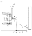
- FIG. 3 is a side sectional view showing a schematic configuration of the switchgear according to the first embodiment. It is an expanded side view of the A section enclosed with the dashed-two dotted line of FIG. It is a perspective view after a partition plate rotates in the A section enclosed with the dashed-two dotted line of FIG.
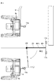
- FIG. 7 is an enlarged side view of a portion of the switchgear according to the second embodiment corresponding to the portion A in FIG. 1.
- Embodiment 1. 1 is a side sectional view showing a schematic configuration of the switch gear 100
- FIG. 2 is an enlarged side view of a portion A surrounded by a two-dot chain line in FIG. 1
- FIG. 3 is a portion A surrounded by a two-dot chain line in FIG.
- FIG. 6 is a perspective view after the partition plate has rotated in FIG.
- the switch gear 100 is a device for supplying power to each load (not shown) connected to the subsequent stage of the switch gear 100.
- the housing 1, which is the grounded portion, is made of metal, and the housing 1 is set to the ground potential.
- the inside of the housing 1 is divided into a plurality of compartments.
- a circuit breaker compartment 3 for accommodating the circuit breaker 2 is arranged on the left side of the drawing (on the front side of the switch gear 100).
- the circuit breaker 2 is a drawer type circuit breaker and can be pulled out from the front side.
- the circuit breaker 2 includes two connection terminals protruding from the rear surface (right side in the drawing).
- the connection terminal on the upper side of the figure is the power supply side terminal 2a, and the connection terminal on the lower side of the figure is the load side terminal 2b.
- a main circuit disconnecting portion 4a for disconnecting the main circuit and a main circuit disconnecting portion 4b are fixedly provided at predetermined intervals in the vertical direction.
- the main circuit disconnecting section 4a and the main circuit disconnecting section 4b can be attached to and detached from the power supply side terminal 2a and the load side terminal 2b.
- a control equipment compartment 5 in which a control device (not shown) is housed is arranged.
- a busbar compartment 8 in which a three-phase busbar 6 is supported and arranged by a support insulator 7 is arranged.
- the bus bar 6 and the main circuit disconnecting section 4a connected to the power source side terminal 2a of the circuit breaker 2 are connected by a branch conductor 9 which is a part of the power feeding conductor.
- a partition plate 13 for partitioning the main circuit disconnecting section 4a and the main circuit disconnecting section 4b is provided below the main circuit disconnecting section 4a.
- the partition plate 13, which is a partition structure for partitioning the inside of the housing 1, is made of a conductive material, and is electrically and mechanically connected to the housing 1, which is a ground portion.
- the partition plate 13 is a member that operates when the internal pressure of the switch gear 100 rises and serves as a pressure release flapper that releases the increased internal pressure. A specific structure of the partition plate 13 will be described.
- the partition plate 13 is formed by bending a metal plate so that the cross section has an L shape.
- the partition plate 13 is configured such that one edge portion of the metal plate turns around a fulcrum 16 and rotates, and a terminal portion 14 is formed at the other end.
- the partition plate 13 When a short circuit accident occurs inside the switchgear 100 and the internal pressure of the switchgear 100 rises, the partition plate 13 maintains the electrical and mechanical connection with the housing 1 which is a grounding portion, Starting from the fulcrum 16 which is the starting point of plastic deformation, the fulcrum is rotated in the direction indicated by the arrow in FIG. By the rotation of the partition plate 13, the terminal portion 14 provided on the tip of the partition plate 13 is electrically and mechanically connected to the terminal portion 15 provided on the branch conductor 9. The branch conductor 9 is grounded by connecting the terminal portion 14 and the terminal portion 15.
- the partition plate 13 after the rotation is shown by a virtual line (two-dot chain line).
- the connection between the terminal portion 14 and the terminal portion 15 is made in all of the three branch conductors 9 that form the three-phase circuit. Short-circuited and grounded. The three-phase grounding extinguishes the arc generated by a short-circuit accident inside the switchgear. Note that the terminal portion 14 and the terminal portion 15 need to be in contact with each other with a contact pressure that can pass a three-phase short-circuit current.
- the switchgear 100 includes a housing 1, a plurality of power supply conductors provided inside the housing 1, and a partition plate 13 that is a partition structure that partitions the inside of the housing 1.
- the plurality of power supply conductors are composed of a branch conductor 9 connected to the power supply side terminal 2a of the circuit breaker 2, a load side conductor 11 connected to the load side terminal 2b of the circuit breaker 2, and a cable 10.
- the upper section contains the busbar compartment 8 and the lower section contains the cable compartment 12.
- the partition plate 13 made of a conductive member partitions the upper partition and the lower partition to partition the partition. For example, in response to an increase in the internal pressure of the switch gear 100 in the upper section or the lower section due to an internal short circuit accident, the pressure receiving surface RP of the partition plate 13 is pressurized by the internal pressure, and the partition plate 13 operates.
- a three-phase circuit is configured by the branch conductor 9 which is a power feeding conductor, and the operation of the partition plate 13 short-circuits the three-phase circuit, so that the partition plate 13 is supplied with a three-phase short-circuit current. Further, the operation of the partition plate 13 connects the branch conductor 9 to the housing 1, which is a grounded portion.
- the branch conductor 9 is provided with a terminal portion 15 formed by bending a plate-shaped body, the partition plate 13 has a terminal portion 14 formed by bending the plate-shaped body, and the terminal portion 14 is integrally formed with the partition plate 13. It is provided.
- the terminal portion 14 and the terminal portion 15 each include a fitting portion C1 and a fitting portion C2 that are integrally provided by bending.
- the terminal portion 14 and the terminal portion 15 are fitted and brought into contact with each other at the fitting portion C1 and the fitting portion C2.
- a predetermined contact pressure maintains an energized connection state sufficient to energize the short-circuit current generated in the branched conductor 9 short-circuited by the contact.
- the fitting portion C1 and the fitting portion C2 are fitted, it is possible to prevent the terminal portion 14 and the terminal portion 15 from being separated from each other due to the rebound caused by the reaction when the partition plate 13 is opened.
- the fitting portion C1 and the fitting portion C2 are fitted together, the electrical and mechanical connection between the terminal portion 14 and the terminal portion 15 will not occur even if the internal pressure of the switchgear drops. Retained.
- the partition structure in the switchgear 100 provided with the partition structure for partitioning the upper partition and the lower partition inside the housing 1, the partition structure operates in response to the internal pressure at the time of an internal short circuit accident, and the partition structure Is in contact with the power supply conductor inside the switchgear 100.
- the partitioning structure that divides the inside of the housing 1 operates in response to a pressure increase due to an internal short-circuit accident, so that the power feeding conductor is short-circuited and the arc is extinguished, so that the configuration is simple and highly reliable. It is possible to obtain the switch gear 100 having the property.
- the partition plate 13 which is a partition structure, has a pressure receiving surface RP, and responds to an internal pressure increase due to an internal short circuit accident in the cable compartment 12 as a lower section, and is a three-phase circuit of the branch conductor 9 as a power supply conductor. Is to be short-circuited. Since the increase in pressure propagates radially from the location where the internal short-circuit accident occurs, the operating direction of the partition structure composed of the partition plate 13 may be reversed depending on the location where the internal short-circuit accident occurs. There is a possibility that the partition structure including the partition plate 13 operates in response to an internal pressure increase due to an internal short-circuit accident in the busbar compartment 8 to short-circuit the three-phase circuit of the branch conductor 9 as the power supply conductor.
- the partition plate 13 which is the partition structure provided in the switch gear 100 according to the first embodiment, has the following configuration, as shown in FIGS. 1 to 3.
- the partition plate 13 is a plate-shaped member having a quadrangular planar shape, and one surface thereof serves as a pressure receiving surface RP of the internal pressure of the switch gear 100.
- the terminal portion 14 of the partition plate 13 is provided in the partition plate 13, and the terminal portion 14 is projected orthogonally to the extending direction of the plate-shaped member.
- the terminal portion 14 is formed by bending.
- the partition structure including the partition plate 13 has an L-shaped cross section, one end serving as a fulcrum 16 for rotating with an increase in internal pressure at the time of an internal short-circuit accident, and the other end for supplying power to the switch gear 100. It is characterized in that the terminal portion 14 connected to the conductor is formed.
- the partitioning structure that partitions the inside of the housing 1 operates in response to a pressure increase due to an internal short-circuit accident, so that the power feeding conductor short-circuits and extinguishes the arc. Can be improved.
- the structure of the partition structure can be a simple structure suitable for operating in response to an increase in internal pressure.
- FIG. 4 is an enlarged side view of a portion of the switchgear 100 corresponding to the portion A in FIG. 1, and shows a side view of the main circuit disconnecting section 4a, the main circuit disconnecting section 4b and their surroundings in the second embodiment.
- the switchgear 100 according to the second embodiment has a configuration in which the terminal portion included in the partition plate is different from that of the first embodiment.
- the partition plate 23 is formed to have a T-shaped cross section, and one end edge portion of the partition plate 23 is configured to rotate as a fulcrum. Moreover, the 1st terminal part 17a and the 2nd terminal part 17b are formed in the other end.
- the partition plate 23 is provided with the first terminal portion 17a and the second terminal portion 17b projecting in the opposite directions so that the partition plate 23 is in the direction of the upper main circuit disconnecting portion 4a or the lower main circuit disconnecting portion 4a.
- the structure is such that the three-phase power supply conductors can be short-circuited and the arc can be extinguished regardless of which direction the part 4b operates.
- FIG. 4 the case where the partition plate 23 operates in the direction of the main circuit disconnecting portion 4b is shown by a virtual line (two-dot chain line).
- the second terminal portion 17b of the partition plate 23 and the terminal portion 15b provided on the load-side conductor 11 come into contact with each other.
- the partition plate 23 operates in the opposite direction and rotates counterclockwise, the first terminal portion 17a of the partition plate 23 and the terminal portion 15a provided on the branch conductor 9 come into contact with each other.
- the partition plate 23 is in contact with the terminal portion 15a near the main circuit disconnecting portion 4a or the terminal portion 15b near the main circuit disconnecting portion 4b, but this configuration is an example. However, the arrangement is not limited to the illustrated arrangement.
- the partition plate 23 that is the partition structure provided in the switch gear 100 according to the second embodiment.
- the partition plate 23 depends on whether the location where the internal pressure of the switchgear 100 has risen, that is, the location where the internal short-circuit accident has occurred is the upper section where the upper electric system is arranged or the lower section where the lower electric system is arranged. Then, either one of the branch conductor 9 that is a power supply conductor that constitutes the higher-order electric system or the load-side conductor 11 that is a power supply conductor that constitutes the lower-order electric system is selected and short-circuited.
- the partition plate 23 is a folded plate-shaped member having a quadrangular planar shape, one surface serving as a first pressure receiving surface RP1 for the internal pressure of the switch gear 100, and the other surface serving as a second internal pressure for the switch gear 100. Of the pressure receiving surface RP2.
- the partition plate 23 is provided with a first terminal portion 17a and a second terminal portion 17b which are pivotally attached to one end edge portion PP and which form a pair with the free end edge portion FP which is the other end edge. 17a and the second terminal portion 17b are orthogonal to the extending direction of the plate-shaped member and project in opposite directions.
- the first terminal portion 17a and the second terminal portion 17b are formed by bending. As shown by the arrow in FIG.
- the second terminal portion 17b is provided with the terminal portion provided on the load-side conductor 11. Fit and contact with 15b.
- the first terminal portion 17a is fitted and comes into contact with the terminal portion 15b provided on the branch conductor 9.
- the partition plate 23 which is a partition structure, can short-circuit either of the power supply conductors on the upper electric system side or the lower electric system side depending on the location where the internal short-circuit accident has occurred.
- the partition plate 23 is formed to have a T-shaped cross section. One end of the partition plate 23 serves as a fulcrum when the switch gear 100 rotates due to an increase in internal pressure at the time of a short circuit accident.
- a first terminal portion 17a and a second terminal portion 17b that are connected to the power supply conductors on the upper electrical system side and the lower electrical system side of the switch gear 100 are formed. Characterize.
- circuit breaker 2 is described as a drawer type here, the circuit breaker 2 is not limited to this and the same effect can be obtained even if the circuit breaker 2 is a fixed type.
Landscapes
- Engineering & Computer Science (AREA)
- Power Engineering (AREA)
- Patch Boards (AREA)
- Gas-Insulated Switchgears (AREA)
Abstract
Cet appareillage de commutation (100) comprend : un boîtier (1); une pluralité de conducteurs d'alimentation électrique disposés à l'intérieur du boîtier; et une structure de séparation qui divise l'intérieur du boîtier (1), le conducteur d'alimentation électrique étant court-circuité par un fonctionnement de la structure de séparation en réponse à la pression interne de l'appareillage de commutation (100).
Priority Applications (2)
| Application Number | Priority Date | Filing Date | Title |
|---|---|---|---|
| DE112019005346.9T DE112019005346T5 (de) | 2018-10-26 | 2019-08-23 | Schaltkasten |
| JP2019568784A JP6667744B1 (ja) | 2018-10-26 | 2019-08-23 | スイッチギヤ |
Applications Claiming Priority (2)
| Application Number | Priority Date | Filing Date | Title |
|---|---|---|---|
| JP2018201363 | 2018-10-26 | ||
| JP2018-201363 | 2018-10-26 |
Publications (1)
| Publication Number | Publication Date |
|---|---|
| WO2020084885A1 true WO2020084885A1 (fr) | 2020-04-30 |
Family
ID=70331335
Family Applications (1)
| Application Number | Title | Priority Date | Filing Date |
|---|---|---|---|
| PCT/JP2019/033054 Ceased WO2020084885A1 (fr) | 2018-10-26 | 2019-08-23 | Appareillage de commutation |
Country Status (2)
| Country | Link |
|---|---|
| DE (1) | DE112019005346T5 (fr) |
| WO (1) | WO2020084885A1 (fr) |
Citations (3)
| Publication number | Priority date | Publication date | Assignee | Title |
|---|---|---|---|---|
| JPS6321408U (fr) * | 1986-07-24 | 1988-02-12 | ||
| JP2004350442A (ja) * | 2003-05-23 | 2004-12-09 | Mitsubishi Electric Corp | スイッチギヤ |
| WO2009001425A1 (fr) * | 2007-06-25 | 2008-12-31 | Mitsubishi Electric Corporation | Appareillage de commutation fermé par métal |
-
2019
- 2019-08-23 DE DE112019005346.9T patent/DE112019005346T5/de active Pending
- 2019-08-23 WO PCT/JP2019/033054 patent/WO2020084885A1/fr not_active Ceased
Patent Citations (3)
| Publication number | Priority date | Publication date | Assignee | Title |
|---|---|---|---|---|
| JPS6321408U (fr) * | 1986-07-24 | 1988-02-12 | ||
| JP2004350442A (ja) * | 2003-05-23 | 2004-12-09 | Mitsubishi Electric Corp | スイッチギヤ |
| WO2009001425A1 (fr) * | 2007-06-25 | 2008-12-31 | Mitsubishi Electric Corporation | Appareillage de commutation fermé par métal |
Also Published As
| Publication number | Publication date |
|---|---|
| DE112019005346T5 (de) | 2021-07-08 |
Similar Documents
| Publication | Publication Date | Title |
|---|---|---|
| CN101814706B (zh) | 开关机构的接地装置 | |
| JP5615839B2 (ja) | 中電圧配電キュービクル | |
| US8975550B2 (en) | Switch unit and switchgear | |
| US9502868B2 (en) | Gas-insulated switchgear | |
| JP2013192369A (ja) | スイッチギヤ | |
| US10693284B2 (en) | Grounding switch for use in metal-clad switchgear | |
| CN106415960A (zh) | 带灭弧器的断路器以及应用该断路器的受配电设备 | |
| WO2014125948A1 (fr) | Appareillage de connexion à isolation gazeuse | |
| JP5026537B2 (ja) | スイッチギヤ | |
| EP3280016B1 (fr) | Appareillage de commutation à isolation gazeuse | |
| CN103872587B (zh) | 配电盘可移动绝缘器 | |
| JP6667744B1 (ja) | スイッチギヤ | |
| EP3709332A1 (fr) | Appareillage de commutation isolé pour systèmes d'alimentation électrique | |
| US10665410B2 (en) | Circuit breaker including active arc control features | |
| JP3102687B2 (ja) | 中圧又は高圧メタルクラッドステーション用のセル及びこの種のセルで作られるステーション | |
| KR20230099166A (ko) | 가스절연 전력개폐장치 | |
| CN111755279A (zh) | 用于配电网的气体绝缘的电气开关设备 | |
| JP2005137147A (ja) | スイッチギヤ | |
| JP6714948B2 (ja) | 遮断器及びスイッチギヤ | |
| KR20240142356A (ko) | 가스절연 개폐장치 | |
| JP4876469B2 (ja) | 配電盤 | |
| US9741512B2 (en) | Switchgear system, and electrical switching apparatus assembly and maintaining method therefor | |
| JP2024158591A (ja) | ガス絶縁開閉装置 | |
| US20220077664A1 (en) | Switching and/or Distributing Device | |
| JP2004236398A (ja) | 受電設備 |
Legal Events
| Date | Code | Title | Description |
|---|---|---|---|
| ENP | Entry into the national phase |
Ref document number: 2019568784 Country of ref document: JP Kind code of ref document: A |
|
| 121 | Ep: the epo has been informed by wipo that ep was designated in this application |
Ref document number: 19875883 Country of ref document: EP Kind code of ref document: A1 |
|
| 122 | Ep: pct application non-entry in european phase |
Ref document number: 19875883 Country of ref document: EP Kind code of ref document: A1 |