WO2020084971A1 - Procédé de soudage à l'arc à des fins d'assemblage de matériaux multiples, élément d'aide à l'assemblage, joint soudé pour matériaux multiples, et matériau en plaque équipé d'un élément d'aide à l'assemblage - Google Patents
Procédé de soudage à l'arc à des fins d'assemblage de matériaux multiples, élément d'aide à l'assemblage, joint soudé pour matériaux multiples, et matériau en plaque équipé d'un élément d'aide à l'assemblage Download PDFInfo
- Publication number
- WO2020084971A1 WO2020084971A1 PCT/JP2019/036831 JP2019036831W WO2020084971A1 WO 2020084971 A1 WO2020084971 A1 WO 2020084971A1 JP 2019036831 W JP2019036831 W JP 2019036831W WO 2020084971 A1 WO2020084971 A1 WO 2020084971A1
- Authority
- WO
- WIPO (PCT)
- Prior art keywords
- plate
- joining
- diameter
- hole
- auxiliary member
- Prior art date
- Legal status (The legal status is an assumption and is not a legal conclusion. Google has not performed a legal analysis and makes no representation as to the accuracy of the status listed.)
- Ceased
Links
Images


Classifications
-
- B—PERFORMING OPERATIONS; TRANSPORTING
- B23—MACHINE TOOLS; METAL-WORKING NOT OTHERWISE PROVIDED FOR
- B23K—SOLDERING OR UNSOLDERING; WELDING; CLADDING OR PLATING BY SOLDERING OR WELDING; CUTTING BY APPLYING HEAT LOCALLY, e.g. FLAME CUTTING; WORKING BY LASER BEAM
- B23K10/00—Welding or cutting by means of a plasma
- B23K10/02—Plasma welding
-
- B—PERFORMING OPERATIONS; TRANSPORTING
- B23—MACHINE TOOLS; METAL-WORKING NOT OTHERWISE PROVIDED FOR
- B23K—SOLDERING OR UNSOLDERING; WELDING; CLADDING OR PLATING BY SOLDERING OR WELDING; CUTTING BY APPLYING HEAT LOCALLY, e.g. FLAME CUTTING; WORKING BY LASER BEAM
- B23K9/00—Arc welding or cutting
- B23K9/007—Spot arc welding
-
- B—PERFORMING OPERATIONS; TRANSPORTING
- B23—MACHINE TOOLS; METAL-WORKING NOT OTHERWISE PROVIDED FOR
- B23K—SOLDERING OR UNSOLDERING; WELDING; CLADDING OR PLATING BY SOLDERING OR WELDING; CUTTING BY APPLYING HEAT LOCALLY, e.g. FLAME CUTTING; WORKING BY LASER BEAM
- B23K9/00—Arc welding or cutting
- B23K9/14—Arc welding or cutting making use of insulated electrodes
-
- B—PERFORMING OPERATIONS; TRANSPORTING
- B23—MACHINE TOOLS; METAL-WORKING NOT OTHERWISE PROVIDED FOR
- B23K—SOLDERING OR UNSOLDERING; WELDING; CLADDING OR PLATING BY SOLDERING OR WELDING; CUTTING BY APPLYING HEAT LOCALLY, e.g. FLAME CUTTING; WORKING BY LASER BEAM
- B23K9/00—Arc welding or cutting
- B23K9/16—Arc welding or cutting making use of shielding gas
- B23K9/167—Arc welding or cutting making use of shielding gas and of a non-consumable electrode
-
- B—PERFORMING OPERATIONS; TRANSPORTING
- B23—MACHINE TOOLS; METAL-WORKING NOT OTHERWISE PROVIDED FOR
- B23K—SOLDERING OR UNSOLDERING; WELDING; CLADDING OR PLATING BY SOLDERING OR WELDING; CUTTING BY APPLYING HEAT LOCALLY, e.g. FLAME CUTTING; WORKING BY LASER BEAM
- B23K9/00—Arc welding or cutting
- B23K9/16—Arc welding or cutting making use of shielding gas
- B23K9/173—Arc welding or cutting making use of shielding gas and of a consumable electrode
-
- B—PERFORMING OPERATIONS; TRANSPORTING
- B23—MACHINE TOOLS; METAL-WORKING NOT OTHERWISE PROVIDED FOR
- B23K—SOLDERING OR UNSOLDERING; WELDING; CLADDING OR PLATING BY SOLDERING OR WELDING; CUTTING BY APPLYING HEAT LOCALLY, e.g. FLAME CUTTING; WORKING BY LASER BEAM
- B23K9/00—Arc welding or cutting
- B23K9/23—Arc welding or cutting taking account of the properties of the materials to be welded
-
- B—PERFORMING OPERATIONS; TRANSPORTING
- B23—MACHINE TOOLS; METAL-WORKING NOT OTHERWISE PROVIDED FOR
- B23K—SOLDERING OR UNSOLDERING; WELDING; CLADDING OR PLATING BY SOLDERING OR WELDING; CUTTING BY APPLYING HEAT LOCALLY, e.g. FLAME CUTTING; WORKING BY LASER BEAM
- B23K9/00—Arc welding or cutting
- B23K9/235—Preliminary treatment
Definitions
- the present invention relates to an arc welding method for joining dissimilar materials, a joining auxiliary member, a dissimilar material welded joint, and a plate material with a joining auxiliary member.
- Patent Document 1 Although the joining method described in Patent Document 1 is a relatively easy method, when the strength of the steel is high, there is a problem that the caulking member cannot be inserted, and the joining strength depends on the frictional force and the caulking member. Since it depends on the rigidity, there is a problem that high joint strength cannot be obtained. Further, when inserting the caulking member, there is a problem that it cannot be applied to the closed cross-section structure because it is necessary to press the caulking member from both the front and back sides with a jig.
- Patent Document 2 cannot be applied to the closed cross-section structure, and the resistance welding method has a problem that the equipment is very expensive.
- Patent Document 3 applies pressure to the steel material surface while plastically flowing the aluminum alloy material in the low temperature region, so that both materials do not melt and prevent the formation of intermetallic compounds. It is said that a metal bonding force can be obtained, and there are also research results that steel and carbon fibers can be joined. However, this joining method is also not applicable to a closed cross-section structure and requires high pressure, so that it is mechanically large and expensive. Also, the joining force does not become so high.
- the existing dissimilar material joining technology has one or more problems such as (i) the members and the groove shape are limited to the open cross-section structure, (ii) the joining strength is low, and (iii) the equipment cost is high. have. Therefore, in order to popularize the multi-material design in which various materials are combined, (i ') applicable to both open cross-section structure and closed cross-section structure, (ii') sufficiently high bonding strength and reliability. There is a demand for a new technology that is easy to use and has all the elements of high cost (iii ') and low cost.
- the present invention has been made in view of the above-mentioned problems, and an object thereof is to dissimilar materials of aluminum alloy (hereinafter also referred to as “Al alloy”) or magnesium alloy (hereinafter also referred to as “Mg alloy”) and steel, Arc welding method for joining dissimilar materials, joining that can be joined with strong and reliable quality using inexpensive arc welding equipment already popular in the world, and can be applied to open cross-section structure and closed cross-section structure without restriction
- An object is to provide an auxiliary member, a dissimilar material welded joint, and a plate member with a joining auxiliary member.
- intermetallic compounds IMC
- welding of steels shows the highest joint strength and reliability. Therefore, the inventors of the present invention have devised a means for achieving welding of dissimilar materials by using welding of steels as a joining force and further utilizing a restraining force.
- An arc welding method for joining dissimilar materials which joins a first plate made of an aluminum alloy or a magnesium alloy and a second plate made of steel, Forming a circular hole in the first plate, It has a stepped outer shape having a shaft portion and a flange portion, at least one press-fitting protrusion portion is provided on the outer peripheral surface of the shaft portion, and a hollow portion penetrating the shaft portion and the flange portion is provided.
- the width of the flange portion is larger than the diameter of the hole of the first plate, and the diameter of the largest circle in contact with the outermost diameter portion of at least two of the protrusions, or the maximum diameter of one of the protrusions.
- B A non-gas arc welding method using the welding wire as a welding electrode.
- C A gas tungsten arc welding method using the welding wire as a non-electrolytic electrode filler.
- D A plasma arc welding method using the welding wire as a non-electrolytic electrode filler.
- E A coated arc welding method in which a coated arc welding rod from which the above-mentioned weld metal of an iron alloy or a Ni alloy is obtained is used as a welding electrode.
- a preferred embodiment of the present invention related to the arc welding method for joining dissimilar materials relates to the following (2) to (11).
- (2) A bulging portion is formed on the second plate by drawing, The arc welding method for joining dissimilar materials according to (1), wherein the bulging portion of the second plate is arranged in the hole of the first plate in the superposing step.
- the arc welding method for joining dissimilar materials according to (1) or (2) further comprising: (4) In the press-fitting step, an adhesive is applied to at least one opposing surface between the joining auxiliary member and the first plate facing the joining auxiliary member, (1) to (3) An arc welding method for joining dissimilar materials according to any one of 1. (5) Any of (1) to (4), wherein an adhesive is applied to the boundary between the joining auxiliary member and the surface of the first plate during the press-fitting step or after the filling and welding step. An arc welding method for joining dissimilar materials according to Crab.
- the height P H1 of the shaft portion of the joining auxiliary member is 10% or more and 100% or less of the plate thickness B H of the first plate, according to any one of (1) to (5) Arc welding method for joining dissimilar materials.
- the maximum diameter circle P D1 in contact with the outermost diameter of the at least two protrusions or the diameter P D1 of a circle in contact with the outer peripheral surface of the the outermost diameter of said one protrusion shank The arc welding method for joining dissimilar materials according to any one of (1) to (6), wherein the diameter B D of the hole of the first plate is 105% or more and 125% or less.
- the outer diameter P D0 of the shaft portion of the joining assisting member is 80% or more and 104% or less with respect to the diameter B D of the hole of the first plate.
- Arc welding method for joining dissimilar materials as described.
- Arc welding method. (10)
- the thickness P H2 of the flange portion of the joining auxiliary member is 50% or more and 150% or less of the plate thickness B H of the first plate, according to any one of (1) to (9). Arc welding method for joining dissimilar materials.
- the above object of the present invention is achieved by the following configuration (12) of the joining auxiliary member.
- a hollow portion is formed, the maximum outer diameter of the shaft portion and the width of the flange portion are each larger than the diameter of the hole of the first plate, and the maximum outer diameter portion of at least two of the protrusion portions is in contact with the maximum outer diameter portion.
- a joining assisting member wherein a diameter of a circle, or a diameter of a circle in contact with the outermost diameter portion of one of the protrusions and the outer peripheral surface of the shaft portion is larger than the diameter of the hole of the first plate.
- a dissimilar material welded joint comprising: a first plate made of an aluminum alloy or a magnesium alloy; and a second plate made of steel which is arc-welded to the first plate,
- the first plate has a circular hole facing the overlapping surface with the second plate, It has a stepped outer shape having a shaft portion and a flange portion, at least one press-fitting protrusion portion is provided on the outer peripheral surface of the shaft portion, and a hollow portion penetrating the shaft portion and the flange portion is provided.
- the width of the flange portion is larger than the diameter of the hole of the first plate, and the diameter of the largest circle in contact with the outermost diameter portion of at least two of the protrusions, or the maximum diameter of one of the protrusions.
- a preferred embodiment of the present invention relating to a dissimilar material welded joint relates to the following (14) to (23).
- (14) The dissimilar material welded joint according to (13), wherein the bulging portion formed on the second plate is arranged in the hole of the first plate.
- At least one of the first plate and the second plate is provided with an adhesive that is provided over the entire circumference of the overlapping surface around the hole, (13) or (14) ) Dissimilar material welded joint.
- an adhesive is provided on at least one opposing surface between the joining auxiliary member and the first plate facing the joining auxiliary member. Dissimilar material welded joint described.
- the above object of the present invention is achieved by the following constitution (24) of the plate member with a joining auxiliary member.
- a plate material with a joining auxiliary member capable of forming a dissimilar material welded joint by arc welding with a steel plate material A plate material made of an aluminum alloy or a magnesium alloy having a circular hole, It has a stepped outer shape having a shaft portion and a flange portion, at least one press-fitting protrusion portion is provided on the outer peripheral surface of the shaft portion, and is a hollow that penetrates the shaft portion and the flange portion.
- the width of the flange part is larger than the diameter of the hole of the plate material, and the diameter of the largest circle in contact with the outermost diameter part of at least two of the protrusions, or the outermost part of one of the protrusions.
- a diameter of a circle contacting the outer peripheral surface of the diameter portion and the shaft portion is larger than the diameter of the hole of the first plate, the joining auxiliary member made of steel, The plate member with a joining auxiliary member, wherein the joining auxiliary member is attached to the plate member by press-fitting the press-fitting protrusion into a hole provided in the plate member.
- a dissimilar material of aluminum alloy or magnesium alloy and steel can be joined with strong and reliable quality by using inexpensive arc welding equipment, and can be applied to both open-section structure and closed-section structure. It can be applied without restrictions.
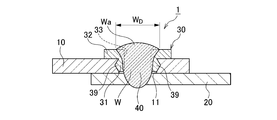
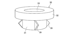
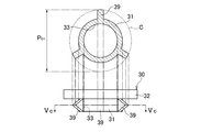
- FIG. 1B is a cross-sectional view of the dissimilar material welded joint taken along the line II of FIG. 1A. It is a perspective view of the joining auxiliary member of this embodiment.
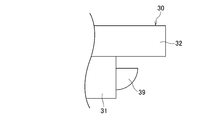
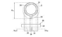
- FIG. 3 is a side view of a joining assisting member of the present embodiment and a sectional view taken along line II-II. It is a principal part side view of the 1st modification of a joining auxiliary member. It is a principal part side view of the 2nd modification of a joining auxiliary member. It is a principal part side view of the 3rd modification of a joining assistance member. It is a principal part side view of the 4th modification of a joining auxiliary member.
- 1B of the dissimilar material welding joint using the joining auxiliary member of the 17th modification It is a front view of the 18th modification of a joining auxiliary member. It is a front view of the 19th modification of a joining auxiliary member. It is a front view of the 20th modification of a joining auxiliary member. It is a front view of the 21st modification of a joining auxiliary member. It is a figure which shows the drilling operation of the arc welding method for joining dissimilar materials of embodiment. It is a figure which shows the press-fitting work of the arc welding method for dissimilar material joining of embodiment. It is a figure which shows the superposition work of the arc welding method for different material joining of embodiment.
- FIG. 9A It is a figure which shows the welding operation of the arc welding method for dissimilar material joining of embodiment. It is sectional drawing which shows the dissimilar material welded joint in which excess is not formed. It is sectional drawing which shows the state which the external stress of the board thickness direction (three-dimensional direction) acted on the dissimilar material welded joint of FIG. 9A. It is sectional drawing which shows the state which the external stress of the plate thickness direction (three-dimensional direction) acted on the dissimilar material welded joint in which the extra heap was formed. It is a sectional view of a dissimilar material welding joint for explaining penetration of welding metal. It is a sectional view of a dissimilar material welding joint for explaining penetration of welding metal.
- FIG. 12B is a cross-sectional view showing a state where shear tension acts on the dissimilar material welded joint of FIG. 12A.
- FIG. 13A shows the dissimilar material welding joint of FIG. 13A.
- FIG. 14A shows the dissimilar material welded joint of FIG. 14A.
- FIG. 15A is a perspective view of the dissimilar material welding joint as a comparative example which carried out the penetration welding of the aluminum upper plate which has a hole, and the steel lower plate.
- FIG. 15B is a cross-sectional view showing a state where shear tension acts on the dissimilar material welded joint of FIG. 15A.
- FIG. 15B is a perspective view showing a state where shear tension acts on the dissimilar material welded joint of FIG. 15A and the joint portion is displaced by nearly 90 °.
- FIG. 17A It is a perspective view which shows the dissimilar material welded joint of FIG. 17A. It is sectional drawing of the dissimilar material welded joint of this embodiment. It is a perspective view which shows the state which the up-and-down peeling tension acted on the dissimilar material welded joint of FIG. 18A. It is sectional drawing which shows the state which shear tension acted on the dissimilar material welded joint of this embodiment. It is sectional drawing which shows the state which shear tension acted on the dissimilar material welded joint of this embodiment in which the intermetallic compound was produced. It is a sectional view of an upper plate, a lower plate, and a joining auxiliary member showing a state before an arc welding in which a gap exists between the upper plate and the lower plate.
- FIG. 6 is a cross-sectional view showing a state in which a stress in a shearing direction is applied to a dissimilar material welded joint using a joining auxiliary member having no protrusion and a shaft portion having a too small diameter.
- FIG. 22B is a cross-sectional view taken along the line XXII-XXII of FIG. 22A. It is a figure which shows the state in which arc welding is performed in the upward posture. It is a side view which shows the 22nd modification of a joining assistance member.
- FIG. 34 is a diagram showing a state before the bulging portion is drawn on the lower plate of FIG. 33.
- FIG. 34 is a diagram showing a state after the bulging portion is drawn on the lower plate of FIG. 33.
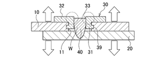
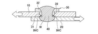
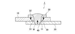
- the arc welding method for joining dissimilar materials of the present embodiment includes an upper plate 10 (first plate) made of an aluminum alloy or a magnesium alloy and a lower plate 20 (second plate) made of steel, which are superposed on each other.
- the welding of the dissimilar material welded joint 1 as shown in FIG. 1A and FIG. 1B is carried out by joining it by the arc welding method described later through the joining auxiliary member 30 made of steel.
- the upper plate 10 is provided with a circular hole 11 penetrating in the plate thickness direction and facing the overlapping surface of the lower plate 20, and the joining assisting member 30 is inserted into the hole 11 by applying pressure.
- the joining assisting member 30 is arranged on the shaft portion 31 arranged in the hole 11 of the upper plate 10 and on the upper surface of the upper plate 10 so as to face outward with respect to the shaft portion 31. It has a flanged portion 32 and a stepped outer shape having. Further, at least one (four in the present embodiment) press-fitting protrusions 39 are provided on the outer peripheral surface of the shaft portion 31.
- the joining auxiliary member 30 is formed with a circular hollow portion 33 that penetrates the shaft portion 31 and the flange portion 32.
- the width P D2 of the flange portion 32 is set to be larger than the diameter B D of the hole 11 of the upper plate 10 (see FIG. 25A). Further, the diameter P D1 of the largest circle C that contacts the outermost diameter portion of the plurality of protrusions 39 is also set to be larger than the diameter B D of the hole 11 of the upper plate 10.
- the protrusion 39 fixes the shaft portion 31 of the joining assisting member 30 in the hole 11 of the upper plate 10 by caulking and restraining force, so that there is no gap between the shaft portion 31 and the hole 11 of the upper plate 10, and
- the shaft portion 31 is formed in a blade shape in consideration of insertability. That is, the maximum outer diameter P D0 of the shaft portion 31 is made smaller than the diameter B D of the hole 11 of the upper plate 10, while the protrusion 39 is made to bite into the wall surface of the hole 11 of the upper plate 10 to partially Eliminate the gap. Further, in consideration of insertability, it is preferable that the shape of the protruding portion 39 gradually increase in radial width from the tip end portion of the shaft portion 31 toward the flange portion side. Furthermore, since the thickness of the protrusion 39 in the circumferential direction is small, the protrusion 39 is in a state close to a line contact with the hole 11 of the upper plate 10, and the pushing pressure is not so much increased.
- the shape of the protrusion 39 may be an isosceles triangle as shown in FIGS. 2A and 2B, but as shown in FIGS. 3A to 3I, other shapes such as triangle, rectangle, partial circle, and trapezoid are typical. And, there is no limit to its shape. Further, since the protrusion 39 is also connected to the lower surface of the flange 32, the strength of the protrusion 39 can be improved. Furthermore, the protrusion 39 may be parallel to the axial direction of the shaft 31 as shown in FIG. 2A, or may be inclined with respect to the axial direction as shown in FIG. 4A. In this case, it is suitable for press-fitting while rotating the joining auxiliary member 30. Further, as shown in FIG. 4B, the protrusion 39 may have a mountain shape whose width in the circumferential direction becomes narrower from the base to the tip.
- the number of the projections 39 is not limited to four as shown in FIG. 2, but may be at least one, and it is not necessary to set an upper limit. That is, as shown in FIGS. 5A to 5E, it may have one, two, three, six, and eight protrusions 39. However, if the number of protrusions 39 increases, the contact area with the holes 11 of the upper plate 10 increases and the pressure required for insertion increases, so the number of protrusions 39 should not be increased more than necessary. It is desirable that the number of protrusions 39 be 8 or less. In addition, as shown in FIG.
- the diameter P D1 of the circle C contacting the outermost diameter portion of one protrusion 39 and the outer peripheral surface of the shaft portion 31 is also the diameter of the upper plate 10. It is set larger than the diameter B D of the hole 11.
- the joining assisting member 30 can be designed by arbitrarily combining the number and shape of the above-mentioned protrusions 39.
- a joining assisting member 30 having three right triangular projections 39 may be configured.
- FIG. 6B is a cross-sectional view corresponding to FIG. 1B of the dissimilar material welded joint 1 when the joining assisting member 30 of FIG. 6A is used.
- the function of the protrusion 39 is substantially the same in any of the above-mentioned joining auxiliary members 30, the following description will be given using an arbitrary joining auxiliary member 30.
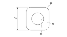
- the outer shape of the flange portion 32 of the joining auxiliary member 30 is not limited to the circular shape as shown in FIGS. 2A and 2B, and may be any shape as long as the hole 11 formed in the upper plate 10 is closed after welding. Can be For example, it may be a polygon having a quadrangle or more shown in FIGS. 7A to 7D. Further, as shown in FIG. 7B, the corners of the polygon may be rounded.
- the width P D2 of the flange portion 32 which will be described later, is defined by the shortest facing surface distance. When the flange portion 32 is circular, the outer diameter is the width P D2 of the flange portion 32.
- the joining assisting member 30 is press-fitted into the upper plate 10, so that the shaft portion 31 is fixed in the hole 11 of the upper plate 10.
- the shaft portion 31 and the hollow portion 33 are located coaxially with the hole 11 of the upper plate 10.
- one protrusion 39 is provided on the shaft portion 31, the shaft portion 31 and the hollow portion 33 are located offset from the holes 11 of the upper plate 10.
- the hollow portion 33 of the joining auxiliary member 30 is filled with the weld metal 40 of the iron alloy or the Ni alloy in which the filler material (welding material) is melted by arc welding, and is also melted with the weld metal 40.
- the lower plate 20 and a part of the joining auxiliary member 30 form a fusion zone W. Therefore, the fusion zone W is also arranged in the hole 11 of the upper plate 10 and welds the joining assisting member 30 and the lower plate 20, whereby the upper plate 10 and the lower plate 20 are joined. .
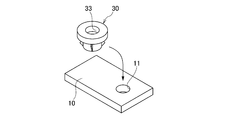
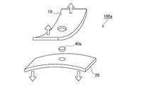
- FIG. 8A a hole 11 is punched in the upper plate 10 (step S1).
- step S2 the joining auxiliary member 30 is press-fitted into the hole 11 of the upper plate 10 from the upper surface of the upper plate 10 (step S2).
- step S3 the press-fitting projection 39 formed on the shaft portion 31 bites into the hole 11 of the upper plate 10 and is press-fitted.
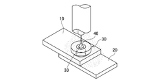
- step S3 a superposing operation for superposing the upper plate 10 and the lower plate 20 is performed (step S3). Then, as shown in FIG.
- Specific methods of the punching work in step S1 include a) punching using a punch, b) press die cutting using a die, c) cutting using a laser, plasma, water jet method or the like.
- step S4 the joining auxiliary member 30 and the lower plate 20 are joined via the weld metal 40 in the hole 11 of the upper plate 10, and the hollow portion 33 provided in the joining auxiliary member 30 is filled. Needed to do. Therefore, insertion of a filler material (welding material) as a filler is essential for arc welding. Specifically, the filler material is melted and the weld metal 40 is formed by the following four arc welding methods.
- the molten electrode gas shield arc welding method is a welding method generally called MAG (Metal Active Gas) or MIG (Metal Inert Gas), and uses a solid wire or a flux-cored wire as a filler / arc-generating molten electrode. It is a method of forming a sound weld by shielding the weld from the atmosphere with a shield gas such as CO 2 , O 2 , Ar, and He.
- MAG Metal Active Gas
- MIG Metal Inert Gas
- the non-gas arc welding method is also called a self-shielded arc welding method, which uses a special flux-cored wire as a filler and arc generating molten electrode, and on the other hand, is a means for forming a sound weld without the need for a shielding gas. is there.
- the gas tungsten arc welding method is a type of gas shielded arc welding method, but it is a non-melting electrode type and is generally called TIG (Tungsten Inert Gas).
- TIG Tungsten Inert Gas
- An inert gas of Ar or He is used as the shield gas.
- An arc is generated between the tungsten electrode and the base material, and the filler wire is laterally fed to the arc.
- the filler wire is not energized, but there is also a hot wire system TIG that energizes the filler wire to increase the melting rate. In this case, no arc is generated in the filler wire.
- the plasma arc welding method has the same principle as TIG, but it is a welding method in which the arc is tightened by double gas systemization and high speed to enhance the arc force.
- the covered arc welding method is an arc welding method using a covered arc welding rod in which flux is applied to a metal core wire as a filler, and does not require a shield gas.
- a commonly used welding wire or welding rod can be applied as long as the welding metal 40 is an Fe alloy. It should be noted that even Ni alloys are applicable because they do not cause any problems in welding with iron.
- JIS JIS, (a) Z3312, Z3313, Z3317, Z3318, Z3321, Z3323, Z3334, (b) Z3313, (c) Z3316, Z3321, Z3334, (d) Z3211, Z3221, Z3223, Z3224, AWS.
- the hollow portion 33 of the joining assisting member 30 is filled with a filler material by using these arc welding methods, but generally, it is not necessary to move the target position of the filler wire or the welding rod, and the arc is generated after an appropriate feeding time. It is enough to cut off and finish welding. However, when the area of the hollow portion 33 is large, the target position of the filler wire or the welding rod may be moved so as to draw a circle in the hollow portion 33.
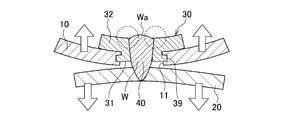
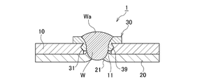
- the weld metal 40 fills the hollow portion 33 of the joining assisting member 30 and further form a swell Wa on the surface of the joining assisting member 30 (see FIG. 1B). If no bulge is formed, that is, as shown in FIG. 9A, when the hollow portion 33 remains in the appearance after welding, the joining strength is insufficient especially against external stress in the plate thickness direction (three-dimensional direction). (See FIG. 9B). Therefore, by forming the extra heap Wa, as shown in FIG. 10, deformation of the joining auxiliary member 30 is suppressed against external stress in the plate thickness direction (three-dimensional direction), and high joining strength is obtained. To be
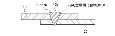
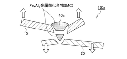
- the upper plate 10 made of aluminum and the lower plate 20 made of steel are simply stacked, and the welding wire made of steel or nickel alloy is placed from the upper plate side.
- the weld metal 40a formed is an alloy of aluminum and steel or an alloy of aluminum, steel and nickel. This alloy exhibits an intermetallic compound (IMC), which is a brittle property due to its high aluminum content.
- IMC intermetallic compound
- the weld metal 40a becomes an intermetallic compound in its entirety. It is also weak and not practical as a welded joint.
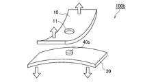
- a method in which a hole 11 having an appropriate size is opened in the upper plate 10 and a welding material of steel or nickel alloy is melted so as to fill the hole 11 can be considered.
- the welding metal 40b formed of the steel and the welding material, which is the lower plate 20 formed in the initial stage of welding does not melt aluminum, an intermetallic compound is not generated, and high strength and toughness are obtained. And is firmly connected to the lower plate 20.
- the weld metal 40b formed inside the hole 11 formed in the upper plate 10 has a very low aluminum melting rate, the generation of intermetallic compounds is significantly suppressed, and the center part has a soundness.
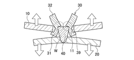
- the two-step-shaped joining auxiliary member 30 having the press-fitting protrusion 39 of the present embodiment is used so as to withstand the tensile stress in the shearing direction and the stress in the vertical peeling direction.
- the upper plate 10 is perforated, and the joining assisting member 30 is press-fitted into the hole 11 provided in the upper plate 10 and then fixed, and then the lower plate 20 to be joined.
- the weld metal 40 is formed by arc welding so as to fill the inside of the upper plate 10 and the joining auxiliary member 30.
- the joining assisting member 30, the weld metal 40, and the lower plate 20 are welded and joined together by a strong metal bond in cross section.
- the largest role of the flange portion 32 of the joining auxiliary member 30 which is wider than the hole 11 provided in the upper plate 10 is resistance to vertical peeling stress.
- FIG. 18A by applying the joining auxiliary member 30 having an appropriate size, it is possible to prevent the phenomenon that the interface between the upper plate 10 and the weld metal 40 peels off and comes off.
- the weld metal 40 sufficiently plastically deforms and then breaks. It is obvious that the joining assisting member 30 does not adversely affect the initial stress even with respect to the tensile stress in the shearing direction.
- the flange portion 32 of the joining auxiliary member 30 to increase the strength against external stress as the area is large and the thickness P H2 is larger thickness direction (three dimensional directions), desirable.
- the size of the joining assisting member 30 is determined according to the required design.
- the joining auxiliary member 30 has a protective wall action for avoiding melting of the Al alloy and the Mg alloy. This function is mainly performed by the shaft portion 31 of the joining auxiliary member 30.
- the most easily melted portion of the joint portion of the Al alloy or the Mg alloy is the inner surface of the hole 11 or the surface around the inner surface.
- the heat of arc welding is prevented from being directly transferred to the Al alloy or the Mg alloy, and is prevented from being mixed with steel to form an intermetallic compound (IMC). If the penetration range of the arc welding is limited to the joining auxiliary member 30 and the lower plate 20, the dilution of Al or Mg into the weld metal 40 becomes zero, and IMC is completely prevented. Therefore, as shown in FIG. 19A, the shaft portion 31 acts as a resistance action against external stress in the plate width direction (two-dimensional direction).
- the occurrence of IMC does not have to be zero, and some IMC formation is allowed.
- the weld metal 40 has ductility and an appropriate strength, the weld metal 40 is external in the plate width direction (two-dimensional direction). This is because the effect of the IMC layer formed around the weld metal 40 is small because it acts as a resistance action against stress.
- the IMC is brittle, even if tensile stress acts on the structure, the joint has a mechanism in which compressive stress and tensile stress are simultaneously applied, and the IMC has sufficient strength against compressive force. Therefore, the formation of the IMC layer does not lead to fracture propagation. Therefore, the shaft portion 31 of the joining assisting member 30 does not necessarily have to have the same thickness as the upper plate 10.
- the joining auxiliary member 30 plays a role of minimizing the gap (gap) generated in the superposed surfaces when the upper plate 10 made of Al alloy or Mg alloy and the lower plate 20 made of steel are superposed ( See FIG. 20A).
- the weld metal 40 undergoes thermal contraction, and at that time, a force acts in a direction in which both the lower plate 20 and the joining auxiliary member 30 approach each other.
- the gap g is reduced after welding, and the joint design accuracy is increased.
- the joining auxiliary member 30 plays a role in each of the shaft portion 31 and the flange portion 32, but the sizes of the shaft portion 31 and the flange portion 32 are important.
- the width P D2 of the flange portion 32 needs to be larger than the diameter B D of the hole 11 provided in the upper plate 10.
- the shaft portion 31 has a simple cylindrical shape without the press-fitting protrusion portion 39 and the outer diameter P D0 of the shaft portion 31 is smaller than the hole diameter B D of the upper plate 10, the diameter difference is industrially increased. Occurs. That is, the smaller the outer diameter P D0 of the shaft portion 31 is than the hole 11 formed in the upper plate 10, the easier the insertion of the shaft portion 31 is. The probability of failing will increase.
- the outer diameter P D0 of the shaft portion 31 is small from the viewpoint of insertability, but the gap formed between the hole 11 provided in the upper plate 10 and the shaft portion 31 of the joining auxiliary member 30 is This causes the upper plate 10 and the lower plate 20 to be displaced from each other. That is, in this joined state, a force for restraining the upper plate 10 in the horizontal direction is not generated, and therefore, when the upper plate 10 receives a shearing stress in the horizontal direction, the joining assisting member 30 and the hole 11 of the upper plate 10 can be relatively easily formed. There is a slippage due to the gap between them.
- the upper plate 10 After the upper plate 10 is displaced by the gap, it does not move easily, but even a slight amount of displacement easily causes a deterioration in design accuracy and is not allowed. Therefore, in the joined state, it is necessary that there is no gap between the joining auxiliary member 30 and the hole 11 of the upper plate 10.
- This state can be achieved by designing the outer diameter P D0 of the shaft portion 31 of the joining assisting member 30 to be larger than the diameter B D of the hole 11 of the upper plate 10 and inserting it under pressure.
- simply increasing the diameter not only makes it difficult to set the target position, but also significantly deteriorates the insertability, and even if the target position is set coaxially, a very high pressure is required.
- the press-fitting projection 39 on the outer peripheral surface of the shaft portion 31, it is possible to eliminate the gap between the shaft portion 31 and the hole 11 of the upper plate 10, and to improve the insertability. Both securing and securing can be achieved. That is, P D0 of the shaft portion 31 is made smaller than the hole diameter B D of the upper plate 10 and, on the other hand, the protrusion 39 bites into the wall surface of the hole 11 of the upper plate 10 to partially eliminate the gap. Since the protrusion 39 has a small thickness in the circumferential direction, the protrusion 39 is in a state close to a line contact with the hole 11 of the upper plate 10 and does not cause a significant increase in the pushing pressure.
- the joining assisting member 30 has a diameter P D1 of the largest circle C that is in contact with the outermost diameter portions of at least two protrusions 39, or the outermost diameter portion of one protrusion 39 and the outer peripheral surface of the shaft portion 31.
- the diameter P D1 of the contacting circle C is larger than the diameter B D of the hole 11 of the upper plate 10.
- the first is that the upper plate 10 and the lower plate 20, which are the joining targets, are hard to rotate relative to each other.
- the cross-sectional shape of the shaft portion 31 of the joining auxiliary member 30 is a true circle
- the joining auxiliary member 30 is joined by press fitting of the shaft portion 31, for example, when a strong horizontal rotational force F R is applied to the upper plate 10, the joining is performed.
- the upper plate 10 may rotate so as to rotate around the auxiliary member 30.
- the joining assisting member 30 is provided with the protrusion 39, and the protrusion 39 bites around the hole 11 of the upper plate 10 to easily prevent rotation. be able to.
- the upper plate 10 and the lower plate 20 can be joined together in any posture. If the press-fitting projection 39 is not provided and the maximum outer diameter P D0 of the shaft 31 is smaller than the diameter B D of the hole 11 of the upper plate 10 so that the shaft 31 can be easily taken in and out, for example, In the upward posture, the joining assisting member 30 falls and cannot be joined. However, as shown in FIG. 23, if the joining assisting member 30 is press-fitted into the hole 11 of the upper plate 10, the joining assisting member 30 does not easily drop, so that joining work is possible.
- the joining assisting members 30 are collectively press-fitted into the upper plate 10 of aluminum or magnesium alloy in a factory different from the joining.
- the joining step since the joining auxiliary member 30 does not easily come off from the upper plate 10, the joining step may be carried out after being transported to the joining factory, and the degree of freedom of the manufacturing step can be increased.
- the method for press-fitting the joining auxiliary member 30 may be any means, but it may be pushed in by a person's hand, hit with a hammer or the like, or a press machine using power such as hydraulic pressure, water pressure, air pressure, gas pressure, or electric drive may be used. There are practical means such as using the power of an industrial robot arm. Further, the joining auxiliary member 30 can be press-fitted by turning it into the hole 11. When such a means is used, as shown in FIG. 24, a screwdriver for screwing fits on the upper surface of the shaft portion 31. Providing the notch 38 makes it easier to turn the joining auxiliary member 30 into the upper plate 10.
- the pushing pressure is strong, not only the shaft portion 31 but also a part of the flange portion 32 may be pushed into the base material of the upper plate 10, but there is no problem. Rather, if the outer diameter of the flange portion 32 is non-circular (see FIGS. 7A to 7D), a part of the flange portion 32 is pushed into the base material of the upper plate 10 so that the upper plate 10 is attached to the lower plate 20. On the other hand, when a rotational force in the horizontal direction is applied, it is desirable to prevent the phenomenon that the caulking effect deviates with a comparatively weak force to rotate.
- the joining auxiliary member 30 is made of steel and has a stepped outer shape having the shaft portion 31 and the flange portion 32, and at least one press-fitting protrusion portion is provided on the outer peripheral surface of the shaft portion 31. 39 is provided, a hollow portion 33 that penetrates the shaft portion 31 and the flange portion 32 is formed, the width P D2 of the flange portion 32 is larger than the hole 11 of the upper plate 10, and the maximum width of at least two protruding portions 39. largest circle C of diameter P D1 in contact with the outer diameter, or the diameter of one hole 11 of the outermost diameter portion and the circle C diameter P D1 upper plate 10 in contact with the outer peripheral surface of the shaft portion 31 of the protrusion 39 B Those larger than D are used. This enables joining of an aluminum alloy or a magnesium alloy, which is generally impossible to weld, to a steel sheet.
- the material of the joining assisting member 30 made of steel is not particularly limited as long as it is pure iron or an iron alloy, and examples thereof include mild steel, carbon steel, stainless steel and the like.
- a surface treatment for forming a film such as an electrically base element, a processed product, an insulating substance, or a passivation on the joining auxiliary member 30 in order to prevent rust of itself and electrolytic corrosion generated between the joining auxiliary member 30 and the aluminum plate.
- Examples thereof include zinc plating, chrome plating, nickel plating, aluminum plating, tin (tin) plating, resin coating, and ceramic coating.
- various dimensions of the joining auxiliary member 30 are set as follows in relation to the upper plate 10 as shown in FIG. 25.
- the shaft height P H1 is designed to be 10% or more and 100% or less of the plate thickness B H of the upper plate 10.
- the shaft portion 31 of the joining assisting member 30 has an effect of preventing melting during the welding process of the Al and Mg upper plate 10 described above. It is preferable that the shaft height P H1 is larger because the heat transfer of the arc heat to the upper plate 10 is prevented. However, if the shaft height P H1 becomes larger than the plate thickness B H of the upper plate 10, a gap is created between the upper plate 10 and the lower plate 20, which is not desirable. Therefore, the upper limit of the shaft height P H1 is 100% with respect to the plate thickness B H. On the other hand, if it is less than 10%, the molten pool of steel comes into contact with aluminum or magnesium, and these are mixed to make the weld metal 40 extremely brittle. Accordingly, the lower limit of the shaft portion height P H1 is 10%.
- the diameter P D1 of the largest circle C that is in contact with the outermost diameter portion of the plurality of protrusions 39 provided on the shaft portion 31 is designed to be 105% or more and 125% or less of the diameter B D of the hole 11 of the upper plate 10.
- the protrusion 39 provided on the shaft portion 31 of the joining assisting member 30 has a function of restraining the caulking by press fitting into the upper plate 10. In order to exert the effect, the diameter P D1 of the maximum circle C must be larger than the hole diameter B D of the upper plate 10.
- the diameter P D1 of the maximum circle C is at least 5% or more larger than the hole diameter B D , appropriate pressure cannot be applied near the upper plate hole. Therefore, the diameter P D1 of the largest circle C is at least 105% or more of the hole diameter B D.
- the larger the diameter P D1 of the largest circle C that is in contact with the outermost diameter portion of the plurality of protrusions 39 the stronger the caulking force, but the greater the force required for press fitting, which impairs the convenience and further It may not be able to withstand the pressure around the upper plate hole and may cause cracks.
- the upper limit of the diameter P D1 of the maximum circle C is determined, and is specifically 125%.
- the diameter P D1 of the circle C contacting the outermost diameter portion of one protrusion 39 and the outer peripheral surface of the shaft 31 is the upper plate. It is designed to be 105% or more and 125% or less with respect to the diameter BD of the ten holes 11.
- the outer diameter P D0 of the shaft portion 31 is designed to be 80% or more and 104% or less with respect to the diameter B D of the hole 11 of the upper plate 10.
- the caulking restraint action on the upper plate 10 by the shaft portion 31 of the joining assisting member 30 is achieved by the protrusion portion 39. If the outer diameter P D0 of the shaft portion 31 is smaller than the hole diameter B D of the upper plate 10, it does not become a resistance factor for insertion and is desirable. However, if the outer diameter P D0 of the shaft portion 31 is excessively small, when the external stress acts on the dissimilar material welded joint 1 after joining, the shaft portion of the joining assisting member 30 is relatively weak in the plate surface direction.
- the outer diameter P D0 of the shaft portion 31 is less than 100% and closer to 100% of the diameter B D of the hole 11 of the upper plate 10.
- the upper limit of the outer diameter P D0 of the shaft portion 31 is allowed to be 104%, which is larger than the hole diameter B D of the upper plate 10.
- the width P D2 of the flange portion 32 is designed to be 105% or more of the diameter B D of the hole 11 of the upper plate 10.
- the flange portion 32 of the joining auxiliary member 30 has a main role as a resistance force against external stress in the plate thickness direction, in other words, when peeling stress acts.
- the shaft portion 31 also has a resistance to the peeling stress to some extent due to the effect of restraining the upper plate 10 by crimping, but the flange portion 32 has a large role.
- the joining assisting member 30 has a larger width P D2 of the flange portion 32 and has a larger thickness, because the joining assisting member 30 has higher strength against external stress in the plate thickness direction (three-dimensional direction).
- the width P D2 of the flange portion 32 is less than 105% of the diameter B DX of the hole 11, the size of the hole 11 of the upper plate 10 is large when the joining assisting member 30 is elastically plastically deformed by external stress in the plate thickness direction. It is easy for the apparent size to be less than the above, and the upper plate 10 is likely to come off. That is, the joining auxiliary member 30 does not exhibit high resistance. Therefore, the width P D2 of the flange portion 32 has a lower limit of 105% of the diameter B D of the hole 11. More preferably, the width P D2 of the flange portion 32 has a lower limit of 120% of the diameter B D of the hole 11. On the other hand, there is no need to set an upper limit from the viewpoint of the strength of the joint.
- the thickness P H2 of the flange portion 32 is designed to be 50% or more and 150% or less of the plate thickness B H of the upper plate 10. As described above, the flange portion 32 of the auxiliary bonding member 30 to increase the strength against external stress large external dimensions, and the thickness P H2 larger the thickness direction (three dimensional directions), desirable. The thickness P H2 of the flange portion 32 exhibits a high resistance by increasing in accordance with the thickness B H of the upper 10 of the joint.
- the flange portion 32 of the joining assisting member 30 When the thickness P H2 of the flange portion 32 is less than 50% of the plate thickness B H of the upper plate 10, the flange portion 32 of the joining assisting member 30 easily undergoes elastic-plastic deformation against external stress in the plate thickness direction, If the apparent size is equal to or smaller than the size of the hole 11 of the upper plate 10, it becomes easy to pull out. That is, the joining auxiliary member 30 does not exhibit high resistance. Therefore, the lower limit of the thickness P H2 of the flange portion 32 is 50% of the plate thickness B H of the upper plate 10.
- the thickness P H2 of the flange portion 32 exceeds 150% of the plate thickness B H of the upper plate 10, there is no problem in terms of joint strength, but the shape is excessively overhanging and the appearance is only poor. It also becomes heavier. Therefore, the thickness P H2 of the flange portion 32 needs to be 150% or less of the plate thickness B H of the upper plate 10.
- the diameter W D of the extra wa is determined by the hollow portion 33 of the joining auxiliary member 30. Is set to 105% or more of the diameter P S of As described above, the joining assisting member 30 has a role of exerting a resistance force against external stress in the plate thickness direction (three-dimensional direction), but does not exert a high resistance force unless the hollow portion 33 is completely filled. If the hollow portion 33 is not completely filled and the inner surface of the hollow portion 33 remains, the joint area between the joining assisting member 30 and the weld metal 40 may be insufficient, and the hollow portion 33 may easily come off.
- the joining assist member 30 and the weld metal 40 be completely filled and the extra wa is formed.
- the diameter W D thereof exceeds the diameter P S of the hollow portion 33 of the joining auxiliary member 30. If the diameter W D of the extra fill Wa is 105% or more of the diameter P S of the hollow portion 33 of the joining assisting member 30, it means that the extra fill has been formed, so this is the lower limit.
- the plate thicknesses of the upper plate 10 and the lower plate 20 are not necessarily limited, the plate thickness of the upper plate 10 is 5.0 mm or less in consideration of the construction efficiency and the shape as lap welding. Is desirable. On the other hand, considering the heat input of arc welding, if the plate thickness is too thin, it will melt down during welding and welding will be difficult. Therefore, it is desirable that both the upper plate 10 and the lower plate 20 be 0.5 mm or more. .
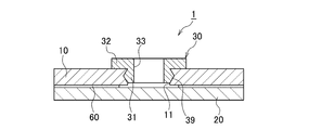
- the adhesive 60 may be annularly applied around the welded portion at the joint surface between the upper plate 10 and the lower plate 20.
- the adhesive 60 may be annularly applied around the welded portion at the joint surface between the upper plate 10 and the lower plate 20.
- This also includes the case of applying it to the entire joint surface except for the above. By this, the electrolytic corrosion rate of the upper plate 10, the lower plate 20, and the weld metal 40 can be reduced.
- the adhesive 60 may be applied between the periphery of the hole 11 of the upper plate 10 and the lower surface of the joining auxiliary member 30. Thereby, the electrolytic corrosion rate of the upper plate 10, the joining auxiliary member 30, and the weld metal 40 can be reduced.
- the adhesive 60 may be applied to the boundary between the joining assisting member 30 and the surface of the upper plate 10. As a result, the effect of reducing the electrolytic corrosion rate can be obtained.
- the coating can be performed only before the welding step, but in the fourth modification shown in FIGS. 29A and 29B, the coating can be performed before the welding step or after the welding step. Is.
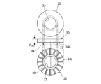
- the contact surface of the joining assisting member 30 with the upper plate 10 does not necessarily have to be a flat surface, as shown in FIG. 30A. That is, the contact surface of the joining assisting member 30 with the upper plate 10 may be provided with slits 34a and 34b as necessary, as shown in FIGS. 30B and 30C.
- a circumferential slit 34a, a lattice slit 34b, or a radial slit (not shown) is provided on the contact surface side with the upper plate 10, the adhesive 60 is applied to the gap between the slits 34a and 34b. Since it enters and does not escape, stable adhesion is achieved and the sealing effect is also ensured. Defining the thickness P H2 of the flange portion 32 of the auxiliary bonding member 30 in the case of such a non-planar surface is the largest part of the height.
- the surface of the hollow portion 33 provided in the joining assisting member 30 may be a cylindrical surface having a uniform diameter, but a screw groove 33a may be formed as shown in FIG.
- a male screw is not used, but the screw groove 33a increases the contact surface area with the molten pool during arc welding, so that the weld metal 40 and the joining auxiliary member 30 are more firmly joined.
- the diameter P S of the hole 11 when it is not a cylindrical surface such as the screw groove 33a is defined as the widest facing distance.
- the bulging portion 21 may be provided on the lower plate 20.
- the plate thickness of the upper plate 10 made of Al alloy or Mg alloy is relatively thin, the lower plate 20 is not processed, the upper plate 10 is perforated, and the joining auxiliary member 30 is inserted into the hole 11 at the time of joining. Good welding is possible by itself.
- the plate thickness of the upper plate 10 is large, it takes time to fill the hollow portion 33 of the joining auxiliary member 30 in the welding process, resulting in poor efficiency.
- the heat input during welding becomes excessive, and the steel plate of the lower plate 20 is likely to melt down before the completion of filling. For this reason, if the bulging portion 21 is provided in the lower plate 20 by drawing, the volume of the hole 11 becomes small, so that filling can be performed while preventing burn-through defects.
- the bulged portion 21 of the lower plate 20 serves as a mark for aligning the upper plate 10 and the lower plate 20, and the bulged portion 21 of the lower plate 20 and the hole 11 of the upper plate 10. Can be easily aligned, which improves the efficiency of overlaying work.
- the peripheral portion of the portion of the lower plate 20 where the bulged portion 21 is formed is restrained by the die 50. Then, as shown in FIG. 34B, pressure is applied to the portion where the bulging portion 21 is formed, and the punch 51 is pushed in to form the bulging portion 21.
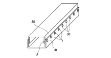
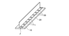
- the welding method of the present embodiment can be said to be spot welding with a small joint area. Therefore, when joining overlapping portions J of practical members having a certain joint area to each other, the present welding method is shown in FIGS. 35A to 35C. As shown, multiple implementations may be performed. As a result, strong joining is performed at the overlapping portion J.
- the present embodiment can be used for an open cross-section structure as shown in FIGS. 35B and 35C, but can be particularly preferably used for a closed cross-section structure as shown in FIG. 35A.
- the arc welding method for joining dissimilar materials of the present embodiment has a step of forming a circular hole 11 in the upper plate 10 and a stepped outer shape having a shaft portion 31 and a flange portion 32. At least one press-fitting projection 39 is provided on the outer peripheral surface of the shaft portion 31, a hollow portion 33 penetrating the shaft portion 31 and the flange portion 32 is formed, and the width P D2 of the flange portion 32 is equal to that of the upper plate 10.
- the diameter P D1 of the largest circle C that is larger than the diameter BD of the hole 11 and is in contact with the outermost diameter portions of at least two protrusions 39, or the outermost diameter portion of one protrusion 39 and the shaft portion 31.
- B A non-gas arc welding method using the welding wire as a welding electrode.
- C A gas tungsten arc welding method using the welding wire as a non-electrolytic electrode filler.
- D A plasma arc welding method using the welding wire as a non-electrolytic electrode filler.
- E A coated arc welding method in which a coated arc welding rod from which a weld metal 40 of an iron alloy or a Ni alloy is obtained is used as a welding electrode.
- the upper plate 10 of the Al alloy or the Mg alloy and the lower plate 20 of the steel can be joined with a strong and reliable quality by using inexpensive arc welding equipment, and an open cross-section structure or a closed cross-section structure can be obtained.
- the bulging portion 21 is formed on the lower plate 20 by drawing, and the bulging portion 21 of the lower plate 20 is arranged in the hole 11 of the upper plate 10 in the superposing process.
- a step of applying an adhesive agent 60 around the entire circumference of the hole 11 on at least one superposing surface of the upper plate 10 and the lower plate 20 is further provided.
- the adhesive acts as a sealing material in addition to improving the joint strength, and can reduce the electrolytic corrosion rate of the upper plate 10, the lower plate 20 and the weld metal 40.
- the adhesive 60 is applied to at least one of the facing surfaces between the joining auxiliary member 30 and the upper plate 10 facing the joining auxiliary member. Thereby, the electrolytic corrosion rate of the upper plate 10, the joining auxiliary member 30, and the weld metal 40 can be reduced.
- the adhesive 60 is applied to the boundary between the joining auxiliary member 30 and the surface of the upper plate 10. Thereby, the bonding strength between the upper plate 10 and the bonding auxiliary member 30 can be improved.
- the height P H1 of the shaft portion 31 of the joining assisting member 30 is 10% or more and 100% or less of the plate thickness B H of the upper plate 10, it is possible to suppress melting of the upper plate 10 during the welding process and perform welding. It is possible to suppress the embrittlement of the metal and prevent the gap between the upper plate 10 and the lower plate 20.
- the diameter P D1 of the largest circle C in contact with the outermost diameter of the at least two projections 39, or, a circle C of diameter P D1 in contact with the outermost diameter portion and the outer peripheral surface of the shaft portion 31 of the protrusion 39 Is 105% or more and 125% or less with respect to the diameter BD of the hole 11 of the upper plate 10, so that the joining assisting member 30 can be caulked and restrained in the hole 11 of the upper plate 10 with an appropriate caulking force.
- the maximum outer diameter P D0 of the shaft portion 31 of the joining assisting member 30 is 80% or more and 104% or less with respect to the diameter B D of the hole 11 of the upper plate 10, it is It is possible to suppress the displacement of the plate 10 and ensure insertability.
- the joining auxiliary member 30 since the width P D2 of the flange portion 32 of the joining auxiliary member 30 is 105% or more with respect to the diameter BD of the hole 11 of the upper plate 10, the joining auxiliary member 30 has a resistance to external stress in the plate thickness direction. Can act as a force.
- the joining auxiliary member 30 since the thickness P H2 of the flange portion 32 of the joining auxiliary member 30 is 50% or more and 150% or less of the plate thickness B H of the upper plate 10, the joining auxiliary member 30 considers appearance and weight increase. At the same time, it can function as a resistance force to external stress in the plate thickness direction.
- the extra wa is formed on the surface of the joining auxiliary member, and the diameter W D of the extra Wa is 105% or more with respect to the diameter P S of the hollow portion 33 of the joining auxiliary member 30. Therefore, the extra wa is capable of functioning as a resistance to external stress in the plate thickness direction.
- the joining assisting member 30 of the present embodiment is made of steel and has a stepped outer shape having a shaft portion 31 and a flange portion 32, and at least one press-fitting projection is provided on the outer peripheral surface of the shaft portion 31.
- the portion 39 is provided, the hollow portion 33 penetrating the shaft portion 31 and the flange portion 32 is formed, and the width P D2 of the flange portion 32 is each larger than the diameter B D of the hole 11 of the upper plate 10, and at least two largest circle C of diameter P D1 in contact with the outermost diameter of projections 39, or the diameter P D1 of the circle C in contact with the outer peripheral surface of the outermost diameter portion of the one protrusion 39 and the shaft portion 31 of the upper plate 10 It is larger than the diameter BD of the hole 11.
- the joining auxiliary member 30 is suitably used in the above-described arc welding method for joining dissimilar materials.
- the dissimilar material welded joint 1 of the present embodiment includes an upper plate 10 made of an aluminum alloy or a magnesium alloy, and a lower plate 20 made of steel that is arc-welded to the upper plate 10, and the upper plate 10 is a lower plate. It has a circular hole 11 facing the overlapping surface with the plate 20, and has a stepped outer shape having a shaft portion 31 and a flange portion 32 which are press-fitted into the hole 11 provided in the upper plate 10. At least one press-fitting projection 39 is provided on the outer peripheral surface of the shaft portion 31, a hollow portion 33 penetrating the shaft portion 31 and the flange portion 32 is formed, and the width P D2 of the flange portion 32 is the upper plate.
- the diameter P D1 of the largest circle C that is larger than the diameter B D of each of the holes 11 and is in contact with the outermost diameter portion of at least two protrusions 39, or the outermost diameter portion and the shaft portion of one protrusion 39.
- 31 diameter P D1 is the upper plate 10 of the circle C in contact with the outer peripheral surface of the Further comprising a diameter B auxiliary bonding member 30 made of steel is larger than D of the hole 11, the hollow portion 33 of the auxiliary bonding member 30 are iron alloys, or, together with is filled with weld metal 40 of Ni alloy, the weld metal 40 And the melted lower plate 20 and a part of the joining auxiliary member 30 form a melted portion W.
- the dissimilar material welded joint 1 including the upper plate 10 of the Al alloy or the Mg alloy and the lower plate 20 of the steel is joined with strong and reliable quality using the inexpensive arc welding equipment, and is opened. It can be applied to both a cross-section structure and a closed cross-section structure without limitation.
- the plate member with a joining assisting member of the present embodiment includes an upper plate (a plate member made of an aluminum alloy or a magnesium alloy) 10 made of an aluminum alloy or a magnesium alloy having a circular hole 11, a shaft portion 31 and a flange portion 32. At least one press-fitting projection 39 is provided on the outer peripheral surface of the shaft portion 31, and a hollow portion 33 penetrating the shaft portion 31 and the flange portion 32 is formed.
- the width P D2 of 32 is larger than the diameter B D of the hole 11 of the upper plate 10, and the diameter P D1 of the largest circle C that is in contact with the outermost diameter portion of at least two protrusions 39, or one protrusion 39.
- the joining assisting member 30 is a joining assisting member made of steel in which a diameter P D1 of a circle C that is in contact with the outermost diameter portion of the shaft 31 and the outer peripheral surface of the shaft portion 31 is larger than the diameter B D of the hole 11 of the upper plate 10, the joining assisting member 30 is , Pressure
- protrusion 39 is press-fitted into the hole 11 provided in the upper plate 10 is attached to the upper plate 19.
- the plate material with the joining auxiliary member can be arc-welded with the steel lower plate (steel plate material) 20 to form a dissimilar material welded joint with strong and highly reliable quality.
Landscapes
- Engineering & Computer Science (AREA)
- Physics & Mathematics (AREA)
- Plasma & Fusion (AREA)
- Mechanical Engineering (AREA)
- Chemical & Material Sciences (AREA)
- Materials Engineering (AREA)
- Arc Welding In General (AREA)
- Butt Welding And Welding Of Specific Article (AREA)
Abstract
L'invention concerne un procédé de soudage à l'arc destiné à l'assemblage de matériaux multiples, allant de l'acier à un alliage d'aluminium ou à un alliage de magnésium, qui permet à des matériaux multiples d'être assemblés solidement et de manière hautement fiable les uns aux autres à l'aide d'un équipement de soudage à l'arc peu coûteux. Ce joint soudé pour matériaux multiples (1) comporte une plaque supérieure en alliage d'aluminium ou en alliage de magnésium, (10) une plaque inférieure en acier (20) soudée à l'arc sur la plaque supérieure (10), et un élément d'aide à l'assemblage d'acier (30). La plaque supérieure (10) a un trou circulaire (11) faisant face à la surface chevauchante de la plaque inférieure (20). L'élément d'aide à l'assemblage (30) présente une forme extérieure étagée comprenant une partie axiale (31) et une partie bride (32), et a une partie creuse (33) formée dans ce dernier qui traverse la partie axiale (31) et la partie bride (32), et la surface périphérique externe de la partie axiale (31) est dotée d'au moins une partie saillante (39) permettant un ajustement par pression. L'élément d'aide à l'assemblage (30) est ajusté par pression dans un trou (11) de la plaque supérieure (10), et la partie creuse (33) est remplie d'un alliage de fer ou d'un métal de soudure en alliage de Ni (40).
Applications Claiming Priority (2)
| Application Number | Priority Date | Filing Date | Title |
|---|---|---|---|
| JP2018199373 | 2018-10-23 | ||
| JP2018-199373 | 2018-10-23 |
Publications (1)
| Publication Number | Publication Date |
|---|---|
| WO2020084971A1 true WO2020084971A1 (fr) | 2020-04-30 |
Family
ID=70330411
Family Applications (1)
| Application Number | Title | Priority Date | Filing Date |
|---|---|---|---|
| PCT/JP2019/036831 Ceased WO2020084971A1 (fr) | 2018-10-23 | 2019-09-19 | Procédé de soudage à l'arc à des fins d'assemblage de matériaux multiples, élément d'aide à l'assemblage, joint soudé pour matériaux multiples, et matériau en plaque équipé d'un élément d'aide à l'assemblage |
Country Status (2)
| Country | Link |
|---|---|
| JP (1) | JP2020066057A (fr) |
| WO (1) | WO2020084971A1 (fr) |
Citations (5)
| Publication number | Priority date | Publication date | Assignee | Title |
|---|---|---|---|---|
| JPS647911U (fr) * | 1987-07-06 | 1989-01-17 | ||
| JP2001132718A (ja) * | 1999-11-05 | 2001-05-18 | Toyota Motor Corp | リベット構造 |
| JP2010096351A (ja) * | 2008-10-20 | 2010-04-30 | Profil Verbindungstechnik Gmbh & Co Kg | コンポーネントアセンブリおよびコンポーネントアセンブリの製造方法 |
| WO2018123716A1 (fr) * | 2016-12-27 | 2018-07-05 | 株式会社神戸製鋼所 | Procédé de soudage à l'arc à des fins d'assemblage de matériaux multiples, élément d'aide à l'assemblage, joint soudé à matériaux multiples, et matériau en plaque équipé d'un élément d'aide à l'assemblage |
| JP2019150831A (ja) * | 2018-02-28 | 2019-09-12 | 株式会社神戸製鋼所 | 異材接合用アーク溶接法 |
-
2019
- 2019-09-19 WO PCT/JP2019/036831 patent/WO2020084971A1/fr not_active Ceased
- 2019-10-21 JP JP2019192176A patent/JP2020066057A/ja active Pending
Patent Citations (5)
| Publication number | Priority date | Publication date | Assignee | Title |
|---|---|---|---|---|
| JPS647911U (fr) * | 1987-07-06 | 1989-01-17 | ||
| JP2001132718A (ja) * | 1999-11-05 | 2001-05-18 | Toyota Motor Corp | リベット構造 |
| JP2010096351A (ja) * | 2008-10-20 | 2010-04-30 | Profil Verbindungstechnik Gmbh & Co Kg | コンポーネントアセンブリおよびコンポーネントアセンブリの製造方法 |
| WO2018123716A1 (fr) * | 2016-12-27 | 2018-07-05 | 株式会社神戸製鋼所 | Procédé de soudage à l'arc à des fins d'assemblage de matériaux multiples, élément d'aide à l'assemblage, joint soudé à matériaux multiples, et matériau en plaque équipé d'un élément d'aide à l'assemblage |
| JP2019150831A (ja) * | 2018-02-28 | 2019-09-12 | 株式会社神戸製鋼所 | 異材接合用アーク溶接法 |
Also Published As
| Publication number | Publication date |
|---|---|
| JP2020066057A (ja) | 2020-04-30 |
Similar Documents
| Publication | Publication Date | Title |
|---|---|---|
| CN109641307B (zh) | 异材接合用电弧点焊法、接合辅助部件及异材焊接接头 | |
| WO2018056172A1 (fr) | Procédé de soudage par points destiné à l'assemblage de différents matériaux, élément auxiliaire d'assemblage et assemblage par soudage de différents matériaux | |
| JP7017501B2 (ja) | 異材接合用溶接法、接合補助部材、及び、異材溶接継手 | |
| KR102225141B1 (ko) | 이재 접합용 아크 용접법, 접합 보조 부재, 이재 용접 이음, 및 접합 보조 부재를 구비한 판재 | |
| JP6829218B2 (ja) | 異材接合用アーク溶接法 | |
| WO2018042680A1 (fr) | Procédé de soudage à l'arc par points à des fins d'assemblage de différents matériaux, élément auxiliaire d'assemblage et assemblage par soudage de différents matériaux | |
| JP2018103240A (ja) | 異材接合用アーク溶接法、接合補助部材、異材溶接継手、及び、接合補助部材付き板材 | |
| WO2018042681A1 (fr) | Procédé de soudage à l'arc par points permettant de joindre des matériaux différents, élément auxiliaire de jonction, et joint de soudage de matériaux différents | |
| JP6999015B2 (ja) | 異材接合用アーク溶接法 | |
| EP3517240A1 (fr) | Procédé de soudage à l'arc pour joindre différents matériaux, élément d'aide à la jonction et joint soudé à différents matériaux | |
| JP2018103241A (ja) | 異材接合用アーク溶接法、接合補助部材、異材溶接継手、及び、接合補助部材付き板材 | |
| JP7025489B2 (ja) | 異材接合用アーク溶接法、接合補助部材、及び、異材溶接継手 | |
| WO2018042682A1 (fr) | Procédé de soudage à l'arc pour joindre différents matériaux, élément auxiliaire de jontoiement et joint de soudage en matériaux différents | |
| WO2020084971A1 (fr) | Procédé de soudage à l'arc à des fins d'assemblage de matériaux multiples, élément d'aide à l'assemblage, joint soudé pour matériaux multiples, et matériau en plaque équipé d'un élément d'aide à l'assemblage | |
| JP2022135926A (ja) | 異材接合用アークスポット溶接法及び異材溶接継手 | |
| JP7131927B2 (ja) | 異材接合法、接合補助部材、及び、異材接合継手 | |
| WO2022185884A1 (fr) | Procédé de soudage à l'arc par points pour assembler des matériaux dissemblables et joint soudé de matériaux dissemblables |
Legal Events
| Date | Code | Title | Description |
|---|---|---|---|
| 121 | Ep: the epo has been informed by wipo that ep was designated in this application |
Ref document number: 19875405 Country of ref document: EP Kind code of ref document: A1 |
|
| NENP | Non-entry into the national phase |
Ref country code: DE |
|
| 122 | Ep: pct application non-entry in european phase |
Ref document number: 19875405 Country of ref document: EP Kind code of ref document: A1 |