WO2020085018A1 - ハイドロゲル膜及びその使用 - Google Patents
ハイドロゲル膜及びその使用 Download PDFInfo
- Publication number
- WO2020085018A1 WO2020085018A1 PCT/JP2019/038854 JP2019038854W WO2020085018A1 WO 2020085018 A1 WO2020085018 A1 WO 2020085018A1 JP 2019038854 W JP2019038854 W JP 2019038854W WO 2020085018 A1 WO2020085018 A1 WO 2020085018A1
- Authority
- WO
- WIPO (PCT)
- Prior art keywords
- hydrogel
- hydrogel film
- film
- dried
- hole
- Prior art date
- Legal status (The legal status is an assumption and is not a legal conclusion. Google has not performed a legal analysis and makes no representation as to the accuracy of the status listed.)
- Ceased
Links
Images





Classifications
-
- A—HUMAN NECESSITIES
- A61—MEDICAL OR VETERINARY SCIENCE; HYGIENE
- A61L—METHODS OR APPARATUS FOR STERILISING MATERIALS OR OBJECTS IN GENERAL; DISINFECTION, STERILISATION OR DEODORISATION OF AIR; CHEMICAL ASPECTS OF BANDAGES, DRESSINGS, ABSORBENT PADS OR SURGICAL ARTICLES; MATERIALS FOR BANDAGES, DRESSINGS, ABSORBENT PADS OR SURGICAL ARTICLES
- A61L27/00—Materials for grafts or prostheses or for coating grafts or prostheses
- A61L27/14—Macromolecular materials
- A61L27/22—Polypeptides or derivatives thereof, e.g. degradation products
- A61L27/24—Collagen
-
- A—HUMAN NECESSITIES
- A61—MEDICAL OR VETERINARY SCIENCE; HYGIENE
- A61L—METHODS OR APPARATUS FOR STERILISING MATERIALS OR OBJECTS IN GENERAL; DISINFECTION, STERILISATION OR DEODORISATION OF AIR; CHEMICAL ASPECTS OF BANDAGES, DRESSINGS, ABSORBENT PADS OR SURGICAL ARTICLES; MATERIALS FOR BANDAGES, DRESSINGS, ABSORBENT PADS OR SURGICAL ARTICLES
- A61L27/00—Materials for grafts or prostheses or for coating grafts or prostheses
- A61L27/50—Materials characterised by their function or physical properties, e.g. injectable or lubricating compositions, shape-memory materials, surface modified materials
- A61L27/52—Hydrogels or hydrocolloids
-
- A—HUMAN NECESSITIES
- A61—MEDICAL OR VETERINARY SCIENCE; HYGIENE
- A61L—METHODS OR APPARATUS FOR STERILISING MATERIALS OR OBJECTS IN GENERAL; DISINFECTION, STERILISATION OR DEODORISATION OF AIR; CHEMICAL ASPECTS OF BANDAGES, DRESSINGS, ABSORBENT PADS OR SURGICAL ARTICLES; MATERIALS FOR BANDAGES, DRESSINGS, ABSORBENT PADS OR SURGICAL ARTICLES
- A61L27/00—Materials for grafts or prostheses or for coating grafts or prostheses
- A61L27/50—Materials characterised by their function or physical properties, e.g. injectable or lubricating compositions, shape-memory materials, surface modified materials
- A61L27/56—Porous materials, e.g. foams or sponges
-
- A—HUMAN NECESSITIES
- A61—MEDICAL OR VETERINARY SCIENCE; HYGIENE
- A61L—METHODS OR APPARATUS FOR STERILISING MATERIALS OR OBJECTS IN GENERAL; DISINFECTION, STERILISATION OR DEODORISATION OF AIR; CHEMICAL ASPECTS OF BANDAGES, DRESSINGS, ABSORBENT PADS OR SURGICAL ARTICLES; MATERIALS FOR BANDAGES, DRESSINGS, ABSORBENT PADS OR SURGICAL ARTICLES
- A61L31/00—Materials for other surgical articles, e.g. stents, stent-grafts, shunts, surgical drapes, guide wires, materials for adhesion prevention, occluding devices, surgical gloves, tissue fixation devices
- A61L31/04—Macromolecular materials
- A61L31/043—Proteins; Polypeptides; Degradation products thereof
- A61L31/044—Collagen
-
- A—HUMAN NECESSITIES
- A61—MEDICAL OR VETERINARY SCIENCE; HYGIENE
- A61L—METHODS OR APPARATUS FOR STERILISING MATERIALS OR OBJECTS IN GENERAL; DISINFECTION, STERILISATION OR DEODORISATION OF AIR; CHEMICAL ASPECTS OF BANDAGES, DRESSINGS, ABSORBENT PADS OR SURGICAL ARTICLES; MATERIALS FOR BANDAGES, DRESSINGS, ABSORBENT PADS OR SURGICAL ARTICLES
- A61L31/00—Materials for other surgical articles, e.g. stents, stent-grafts, shunts, surgical drapes, guide wires, materials for adhesion prevention, occluding devices, surgical gloves, tissue fixation devices
- A61L31/14—Materials characterised by their function or physical properties, e.g. injectable or lubricating compositions, shape-memory materials, surface modified materials
- A61L31/145—Hydrogels or hydrocolloids
-
- A—HUMAN NECESSITIES
- A61—MEDICAL OR VETERINARY SCIENCE; HYGIENE
- A61L—METHODS OR APPARATUS FOR STERILISING MATERIALS OR OBJECTS IN GENERAL; DISINFECTION, STERILISATION OR DEODORISATION OF AIR; CHEMICAL ASPECTS OF BANDAGES, DRESSINGS, ABSORBENT PADS OR SURGICAL ARTICLES; MATERIALS FOR BANDAGES, DRESSINGS, ABSORBENT PADS OR SURGICAL ARTICLES
- A61L31/00—Materials for other surgical articles, e.g. stents, stent-grafts, shunts, surgical drapes, guide wires, materials for adhesion prevention, occluding devices, surgical gloves, tissue fixation devices
- A61L31/14—Materials characterised by their function or physical properties, e.g. injectable or lubricating compositions, shape-memory materials, surface modified materials
- A61L31/146—Porous materials, e.g. foams or sponges
-
- A—HUMAN NECESSITIES
- A61—MEDICAL OR VETERINARY SCIENCE; HYGIENE
- A61L—METHODS OR APPARATUS FOR STERILISING MATERIALS OR OBJECTS IN GENERAL; DISINFECTION, STERILISATION OR DEODORISATION OF AIR; CHEMICAL ASPECTS OF BANDAGES, DRESSINGS, ABSORBENT PADS OR SURGICAL ARTICLES; MATERIALS FOR BANDAGES, DRESSINGS, ABSORBENT PADS OR SURGICAL ARTICLES
- A61L2430/00—Materials or treatment for tissue regeneration
- A61L2430/22—Materials or treatment for tissue regeneration for reconstruction of hollow organs, e.g. bladder, esophagus, urether, uterus
-
- A—HUMAN NECESSITIES
- A61—MEDICAL OR VETERINARY SCIENCE; HYGIENE
- A61L—METHODS OR APPARATUS FOR STERILISING MATERIALS OR OBJECTS IN GENERAL; DISINFECTION, STERILISATION OR DEODORISATION OF AIR; CHEMICAL ASPECTS OF BANDAGES, DRESSINGS, ABSORBENT PADS OR SURGICAL ARTICLES; MATERIALS FOR BANDAGES, DRESSINGS, ABSORBENT PADS OR SURGICAL ARTICLES
- A61L2430/00—Materials or treatment for tissue regeneration
- A61L2430/34—Materials or treatment for tissue regeneration for soft tissue reconstruction
Definitions
- the present invention relates to hydrogel membranes and their uses. More specifically, the present invention relates to a hydrogel film, a dried product of a hydrogel film, an apparatus for producing a hydrogel film or a dried product of a hydrogel film, a method for producing a hydrogel, a method for producing a hydrogel film, and a hydrogel. And a method for producing the dried body of the hydrogel film.
- the present application claims priority based on Japanese Patent Application No. 2018-201946 filed in Japan on October 26, 2018, and the content thereof is incorporated herein.
- Patent Document 1 and Non-Patent Document 1 describe that the effect of preventing esophageal stenosis and promoting epithelialization can be obtained by applying an atelocollagen vitrigel membrane to the excised mucosa of the esophagus. Similar procedures are believed to be useful for digestive tracts other than the esophagus. Further, not limited to the medical field, there is generally a demand for bringing a hydrogel film into close contact with an uneven surface.
- an object of the present invention is to provide a technique for bringing a hydrogel film into close contact with an uneven surface.
- the present invention includes the following aspects.
- [1] A hydrogel film having a plurality of through holes penetrating one surface and the other surface.
- [4] The hydrogel film according to [1] or [2], wherein the through holes have a density of 1 to 1,000,000 holes / cm 2 .
- [5] The hydrogel film according to any one of [1] to [4], wherein the hydrogel contains native collagen or atelocollagen.
- a production method comprising a step (f) of obtaining a hydrated hydrogel film.
- (A) is a schematic diagram explaining an example of the hydrogel film of this embodiment. 6B is a sectional view taken along line bb ′ of FIG. It is a photograph which shows an example of the manufacturing apparatus of this embodiment.
- (A) is a photograph showing a state in which the side surface portion of the production apparatus is removed from the hydrogel film in Production Example 1.
- (B) is a photograph showing a state where the columnar member is removed from the hydrogel film in Production Example 1.
- (C) and (d) are photographs of the hydrogel taken out from the production apparatus in Production Example 1.
- (A) And (b) is a photograph of the hydrogel dried body after vitrification in manufacture example 1.
- (C) is a photograph of the hydrogel film after the first rehydration in Production Example 1.
- (D) is a photograph of the hydrogel film after the second rehydration in Production Example 1.
- (E) is a photograph of the hydrogel film after the third rehydration in Production Example 1.
- (A)-(d) and (f) are photographs of each step in Production Example 6.
- (E) is a photomicrograph of the through holes of the dried hydrogel after vitrification, and (g) is the through holes of the hydrogel film after rehydration.
- (A), (d), (g), (j), and (m) are photographs of the hydrogel films of Production Examples 1 to 5, respectively. Further, (b) and (c), (e) and (f), (h) and (i), (k) and (l), (n) and (o) are Production Examples 1 to 5, respectively.
- FIG. 2 is a micrograph of the hydrogel film of FIG.
- A is a photograph showing the results of Experimental Example 2 in which an atelocollagen vitrigel film having no through holes was brought into close contact with an uneven surface.
- B is a photograph showing the results of Experimental Example 2 in which the hydrogel film of Production Example 2 was brought into close contact with the uneven surface.
- C is a photograph showing the results of Experimental Example 2 in which the hydrogel film of Production Example 1 was brought into close contact with the uneven surface.
- 7 is a photograph showing a state in which a conical tube is covered with each hydrogel film in Experimental Example 3.
- (A) is a photograph showing a state in which the conical tube on which the atelocollagen vitrigel membrane having no through hole is fixed is inverted in Experimental Example 3.
- (B) is a photograph showing a state in which the inverted conical tube was brought into contact with cardboard in Experimental Example 3.
- (C) is a photograph taken in Experimental Example 3 in which no trace of water was observed as a result of contact with thick paper.
- 7 is a photograph showing a state in which the conical tube on which the hydrogel film of Production Example 2 is fixed is inverted in Experimental Example 3.
- (A) is a photograph showing a state in which the conical tube on which the hydrogel film of Production Example 1 is fixed is inverted in Experimental Example 3.
- (B) is a photograph showing a state in which the inverted conical tube was brought into contact with the cardboard approximately 15 minutes after the conical tube was inverted in Experimental Example 3.
- (C) is a photograph of a state in which traces of water were observed as a result of contact with thick paper in Experimental Example 3.
- the present invention provides a hydrogel membrane having a plurality of through holes penetrating one surface and the other surface.
- FIG. 1 is a schematic diagram illustrating an example of the hydrogel film of this embodiment.
- FIG. 1A is a perspective view of the hydrogel film 100.
- the hydrogel film 100 has one surface 110 and the other surface 120. Further, the hydrogel film 100 has a plurality of through holes 130 penetrating the one surface 110 and the other surface 120.
- FIG. 1B is a sectional view taken along the line bb 'of FIG. 1A.
- the hydrogel film of the present embodiment can be easily attached to the uneven surface. Further, even when the uneven surface is a wound part of the living body and the exudate can be exuded from the uneven surface, the exudate can be passed through the through-holes, so that the adhesion of the hydrogel film to the uneven surface can be maintained. it can.
- the "hydrogel film having a through hole" may be referred to as a "porous hydrogel film".
- sol means that colloidal particles of dispersoid having a liquid as a dispersion medium (particle diameter of about 1 to several hundred nm) are composed of a polymer compound in particular. More specific sols include aqueous solutions of natural polymer compounds and synthetic polymer compounds. Therefore, when these polymer compounds have a network structure due to a chemical bond, they are transformed into "hydrogel” which is a semi-solid state substance having a large amount of water in the network. That is, the “hydrogel” means a gel of sol. More specific examples of the hydrogel include gels formed by introducing crosslinks into an artificial material of a natural polymer compound or a synthetic polymer compound.
- the “membrane” can be called a sheet.
- the thickness of the hydrogel film of the present embodiment can be appropriately set according to need, and may be, for example, 0.1 ⁇ m to 5 mm, for example, 2 ⁇ m to 1 mm, for example, 20 ⁇ m to 400 ⁇ m. It may be.
- a hydrogel having a thickness of more than 5 mm is called a hydrogel and may be distinguished from a hydrogel film.
- the opening area of the through-hole on one surface of the hydrogel film may be the same as or different from the opening area of the through-hole on the other surface of the hydrogel film.
- the opening area of the through hole on one surface of the hydrogel film may be smaller than the opening area of the through hole on the other surface of the hydrogel film.
- the area of one surface of the hydrogel film is larger than the area of the other surface of the hydrogel film.
- the uneven surface is a wound part of a living body
- the opening area of the through hole is small, the exudate can be passed through the through hole, and the hydrogel It is possible to maintain close contact with the uneven surface of the film.
- the opening area of the through-hole on one surface of the hydrogel film is different from the opening area of the through-hole on the other surface of the hydrogel film, the opening area of the through-hole on one surface of the hydrogel film, The ratio of the opening area of the through hole on the other surface may be, for example, about 100: 1 to 1: 100, 50: 1 to 1:50, or 10: 1 to 1:10. It may be.
- the cylindrical blade include medical instruments such as a trepan.
- the shape of the blade may be appropriately changed according to the sectional shape of the through hole, and is not limited to the cylindrical shape.
- a hydrogel film in which the opening area of the through-hole on one surface of the hydrogel film and the opening area of the through-hole on the other surface of the hydrogel film are the same can be obtained by laser irradiation after forming the hydrogel film. It can also be manufactured by forming a through hole having the same opening area on one side and the opening area on the other side.
- the opening area of the through-hole on one surface of the hydrogel film and the opening area of the through-hole on the other surface of the hydrogel film are different, for example, after forming the hydrogel film, by laser irradiation, the through-hole It can be manufactured by forming or the like.
- the irradiation angle of the laser or the like it is possible to manufacture a hydrogel film in which the opening area of the through hole on one surface of the hydrogel film and the opening area of the through hole on the other surface of the hydrogel film are different. it can.
- a hydrogel film in which the opening area of the through-hole on one surface of the hydrogel film and the opening area of the through-hole on the other surface of the hydrogel film are different is manufactured by the manufacturing method described below using a manufacturing apparatus described below. be able to.
- the material of the hollowed-out portion is wasted.
- the material of the part cut out by laser irradiation is wasted, and the part irradiated by laser is denatured by heat, which is a problem. May be.
- the area of the hydrogel film of the present embodiment can be appropriately set as needed, and may be, for example, 1 mm 2 to 400 cm 2 , for example, 20 mm 2 to 40 cm 2 , and for example, 80 mm 2 to It may be 4 cm 2 .
- the hydrogel film of this embodiment has through holes.
- the shape of the plane perpendicular to the axial direction of the through hole (hereinafter, sometimes referred to as the cross-sectional shape of the through hole) is not particularly limited, and examples thereof include triangle, quadrangle (including square, rectangle, and trapezoid), pentagon, hexagon, A polygon such as a heptagon or an octagon; a circle, an ellipse, a substantially circle, an ellipse, a substantially ellipse, a semicircle, a fan shape, or the like.
- the cross-sectional shape of the through hole may be constant or may change in the middle.
- the hydrogel film may have a plurality of types of through holes having different shapes.
- the diameter of the through-hole of the hydrogel film means the diameter of the circle assuming the circle having the same area as the widest cross-sectional area among the cross-sectional areas of the plane perpendicular to the axial direction of the through-hole. I shall.
- the diameter of the through hole of the hydrogel film of this embodiment may be 0.1 ⁇ m to 5 mm, 1 ⁇ m to 2 mm, or 10 ⁇ m to 1 mm.
- the diameter of the through hole does not have to be constant.
- a plurality of types of through holes having different diameters may be mixed.
- the diameter of the through hole may be different depending on the position of the hydrogel film.
- the density of through holes can be appropriately set as necessary, and may be 1 to 1,000,000 pieces / cm 2 , or 1 to 10,000 pieces / cm 2. it may be cm 2, and may be 1 to 100 pieces / cm 2. When the diameter of the through holes is about 0.1 ⁇ m, the density of the through holes may be higher than 1,000,000 holes / cm 2 .
- the density of the through holes may differ depending on the position of the hydrogel film.
- the through hole may have a higher density in the central portion of the hydrogel film than in the surrounding area.
- the density of the through holes may be lower in the central portion of the hydrogel film than in the surroundings.
- sols that is the material of the hydrogel membrane of the present embodiment include gelling extracellular matrix-derived components, natural polymer compounds such as fibrin, agar, agarose, and cellulose, and polyacrylamide, polyvinyl alcohol, polyethylene oxide, Synthetic polymer compounds such as poly (II-hydroxymethylmethacrylate) / polycaprolactone are included.
- extracellular matrix-derived component examples include collagen (type I, type II, type III, type V, type XI, etc.), mouse EHS tumor extract (type IV collagen, laminin, heparan sulfate proteoglycan, etc.) (Including) and a basement membrane component (trade name “matrigel”), glycosaminoglycan, hyaluronic acid, proteoglycan, gelatin, and the like, but are not limited thereto.
- a desired hydrogel film can be produced by selecting the components such as salt, concentration, pH, etc. that are optimal for gelation.
- the sol is preferably an extracellular matrix-derived component that gels, and collagen is more preferable. Further, among collagen, native collagen or atelocollagen is more preferable.
- the present invention provides a dried body of the hydrogel film described above.
- the above-mentioned hydrogel film may be dried to obtain a dried body.
- free water in the hydrogel can be completely removed, and further partial removal of bound water can be promoted.
- Vitrigel (registered trademark) can be obtained by rehydrating the dried body of the present embodiment with phosphate buffered saline (PBS), a culture solution, or the like.
- PBS phosphate buffered saline
- Vitrigel refers to a gel in a stable state obtained by rehydrating a vitrification product obtained by drying a conventional hydrogel, and the present inventor has referred to it as “vitrigel”. (Registered trademark) ”. In the following, when the term “vitrigel” is used, the term “(registered trademark)” may be omitted.
- the vitrigel obtained by rehydration after short-term drying may be washed with PBS or the like and re-vitrified.
- drying method various methods such as air drying, drying in a closed container (circulating the air in the container to constantly supply dry air), and drying in an environment where silica gel is placed may be used. it can.
- air-drying method it is dried in a thermo-hygrostat kept at 10 ° C. 40% relative humidity for about 2 days, and in a sterile clean bench for about 24 hours at room temperature. Etc.
- a dried body of hydrogel that has not been rehydrated after being dried may be simply referred to as “dried body of hydrogel”.
- the gel obtained by hydrating the hydrogel after drying may be referred to as a “vitrigel”, and the dried product obtained by drying the vitrigel may be referred to as a “vitrigel dried product”.
- a film-shaped hydrogel may be simply referred to as a “hydrogel film”, and a film-shaped vitrigel may be simply referred to as a “vitrigel film”.
- the dried product of the obtained vitrigel film may be irradiated with ultraviolet rays.
- a known ultraviolet irradiation device can be used for the irradiation of ultraviolet rays.
- UV irradiation energy to Bitorigeru membrane dryer body a total irradiation dose per unit area is preferably from 0.1mJ / cm 2 ⁇ 6000mJ / cm 2, is 10mJ / cm 2 ⁇ 4000mJ / cm 2 it is more preferable, and further preferably 100mJ / cm 2 ⁇ 3000mJ / cm 2.
- the total irradiation amount is within the above range, the transparency and strength of the vitrigel membrane material obtained by the subsequent rehydration can be made particularly preferable.
- the irradiation of the dried vitrigel membrane with ultraviolet light may be repeated multiple times.
- the steps of rehydration and re-vitrification of the dried vitrigel membrane subjected to ultraviolet irradiation treatment are performed, and then the second time. It is preferable to irradiate the dried body of the vitrigel film material after the subsequent revitrification with ultraviolet rays.
- the irradiation of ultraviolet rays to the dried vitrigel membrane is repeatedly performed by dividing into multiple times, and the transparency of the vitrigel membrane material obtained in the subsequent rehydration step is increased. And the strength can be further increased.
- the larger the number of divisions the better. For example, when the total amount of irradiation of the dried vitrigel membrane with ultraviolet light per unit area is in the range of 1000 mJ / cm 2 to 4000 mJ / cm 2 , the number of irradiations in the range is 2 to 10 times. Or 2 to 6 times.
- the irradiation site of the ultraviolet rays is divided into one side and the other side of the dried vitrigel membrane, and the total irradiation amount is applied to the dried vitrigel membrane.
- the total irradiation amount of ultraviolet rays per unit area may be set.
- the strength and transparency of the vitrigel membrane material obtained in the subsequent rehydration step are increased because the polymer compounds in the vitrigel membrane material are crosslinked by ultraviolet rays. It is thought to be because of this. That is, by the operation, high transparency and strength can be imparted to the vitrigel film material.
- the obtained dried vitrigel membrane subjected to the ultraviolet irradiation treatment may be rehydrated with PBS, a culture solution or the like to be used as a vitrigel membrane material.
- the obtained vitrigel film material may be dried to be re-vitrified to obtain a dried vitrigel film material.
- a vitrigel membrane material obtained by subjecting a dried vitrigel membrane to ultraviolet irradiation treatment a gel film obtained by hydrating the vitrigel membrane material.
- a gel film obtained by hydrating the vitrigel membrane material May be referred to as “vitrigel film material”
- a dried product obtained by drying the vitrigel film material may be referred to as “dried product of vitrigel film material”.
- the "vitrigel membrane” and “vitrigel membrane material” are hydrates.
- the present invention provides a manufacturing apparatus including a container part having a bottom surface part and a side surface part, and a plurality of columnar jigs that can be arranged in contact with the bottom surface part.
- the manufacturing apparatus of the present embodiment is for manufacturing the above-mentioned hydrogel film or a dried body of the hydrogel film.
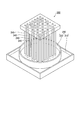
- FIG. 2 is a photograph showing an example of the manufacturing apparatus of this embodiment.
- the manufacturing apparatus 200 includes a container portion 230 having a bottom surface portion 210 and a side surface portion 220, and a plurality of columnar jigs 240 that can be arranged in contact with the bottom surface portion 210.
- sol is injected into the container part 230. Then, the sol is gelated in a state where the columnar jig 240 is arranged so as to be in contact with the bottom surface portion 210. Then, when the columnar jig 240 is removed, a hydrogel in which the portion where the columnar jig 240 was present is a through hole is obtained. That is, the through holes of the hydrogel are formed by the columnar jig 240. Since the columnar jig 240 gels in a state of being in contact with the bottom surface portion 210, the formed through hole is one that penetrates one surface and the other surface of the hydrogel.
- the through-hole on the bottom surface of the hydrogel tends to be narrowed by being pushed from the surroundings by the weight of the hydrogel film. Therefore, the opening area of the through hole on the bottom surface of the hydrogel tends to be smaller than the opening area of the through hole on the other surface of the hydrogel film.
- Examples of the material of the bottom surface portion 210, the side surface portion 220, and the columnar jig that constitute the manufacturing apparatus 200 include, but are not limited to, glass material, polyacrylate (acrylic resin), polystyrene, nylon, stainless steel, and the like.
- the glass material include soda-lime glass, Pyrex (registered trademark) glass, Vycor (registered trademark) glass, and quartz glass.
- polyacrylate (acrylic resin) for example, poly (methyl methacrylate), poly (ethyl methacrylate), poly (butyl methacrylate), poly (isobutyl methacrylate), poly (hexyl methacrylate), Poly (isodecyl methacrylate), poly (lauryl methacrylate), poly (phenyl methacrylate), poly (methyl acrylate), poly (isopropyl acrylate), poly (isobutyl acrylate), poly (octadecyl acrylate), etc. Can be mentioned.
- At least the side surface portion 220 is transparent because it becomes easy to inject the sol into the container portion 230, confirm the gelation, etc. during the production of the hydrogel.
- the present invention is a method of manufacturing a hydrogel having a plurality of through holes penetrating one surface and the other surface, which is a step (a) of injecting sol into the container portion 230 of the manufacturing apparatus described above. ), A step (b) of arranging the plurality of columnar jigs 240 in contact with the bottom surface portion 210 before or after the injection of the sol, and a step of allowing the sol to stand and gel to obtain a hydrogel ( and a step (d) of removing the plurality of columnar jigs 240 to obtain a hydrogel having a plurality of through holes penetrating one surface and the other surface.
- the produced hydrogel having a plurality of through holes may be a vitrigel film having a plurality of through holes by repeating the drying step and the hydration step once or a plurality of times. That is, the manufacturing method of the present embodiment includes a step (e) of drying the hydrogel obtained in the step (d) to obtain a dried body, and a hydrated hydrogel film obtained by hydrating the dried body. The method for producing a hydrogel film may further include the step (f) of obtaining.
- the collagen sol When the sol injected in the step (a) is a collagen sol, the collagen sol has an optimum salt concentration, for example, physiological saline, phosphate buffered saline (PBS), HBSS (Hank's Balanced). Salt solution), a basal culture solution, a serum-free culture solution, a serum-containing culture solution, etc. can be used. Further, the pH of the solution at the time of gelatinizing the collagen can be set to 6 to 8, for example.
- the collagen sol may be prepared, for example, at about 4 ° C.
- the hydrogel film obtained by using the serum-free culture solution is suitable for medical use.
- the concentration of the collagen sol for producing the hydrogel is preferably 0.1 to 1.0% by mass, more preferably 0.2 to 0.6% by mass.
- concentration of the collagen sol is equal to or higher than the lower limit, gelation is not too weak, and when the concentration of the collagen sol is equal to or lower than the upper limit, a hydrogel composed of a uniform collagen gel can be obtained. .
- step (b) a plurality of columnar jigs 240 are arranged so as to be in contact with the bottom surface portion 210. This may be performed before or after the injection of the sol into the container portion 230.
- step (c) the sol is allowed to stand and gelated to obtain a hydrogel.
- the temperature for keeping the sol warm can be appropriately adjusted depending on the type of the sol used.
- the heat retention during gelation can be lower than the denaturation temperature of collagen depending on the animal species of the collagen used, and is generally 20 ° C or higher and 37 ° C or lower.
- gelation can be performed within a few minutes to a few hours.
- step (d) the plurality of columnar jigs 240 are removed to obtain a hydrogel having a plurality of through holes penetrating one surface and the other surface.
- the hydrogel may be used as it is, or may be further used in the steps (e) and (f) by repeating drying and hydration to produce a vitrigel film, which may be used as the vitrigel film.
- the present invention is a method for manufacturing a dried body of hydrogel having a plurality of through holes penetrating one surface and the other surface, wherein sol is injected into the container portion 230 of the manufacturing apparatus described above.
- Step (a) step (b) of arranging the plurality of columnar jigs 240 in contact with the bottom surface portion 210 before or after injecting the sol, and allowing the sol to stand and gel to form hydrogel.
- the dried product of hydrogel produced may be a dried vitrigel film by repeating the hydration step and the drying step once or several times. That is, the production method of the present embodiment includes a step (f) of hydrating the dried product of the hydrogel obtained in the step (e) to obtain a hydrated hydrogel film, and a step (f).
- the method for producing a dried body of a hydrogel film may further include the step (e2) of drying the obtained hydrogel film to obtain a dried body of the hydrogel film.
- steps (a) to (e) are the same as those described above.
- the step (e2) is the same as the step (e) except that the object to be dried is a hydrogel or a hydrogel film.
- the hydrogel can be manufactured as follows without using the above-mentioned apparatus. First, the sol is injected into a suitable container. Then, the sol is allowed to stand and gelated to obtain a hydrogel. Subsequently, the through hole is formed by hollowing out the hydrogel using a cylindrical blade or the like. Examples of the cylindrical blade include medical instruments such as a trepan. The shape of the blade may be appropriately changed according to the sectional shape of the through hole, and is not limited to the cylindrical shape.
- through holes may be formed in the hydrogel film by laser irradiation.
- the produced hydrogel may be dried to give a dried hydrogel (membrane).
- the drying step and the hydration step may be repeated once or a plurality of times to obtain a vitrigel film or a dried vitrigel film.
- 16 mL of serum-free culture solution was dispensed into a 50 mL conical tube on ice. Subsequently, 16 mL of porcine atelocollagen (Kanto Chemical Co., Inc., collagen concentration 1% by mass) was added to prepare a uniform collagen sol.
- porcine atelocollagen Kerat Chemical Co., Inc., collagen concentration 1% by mass
- 20 mM HEPES catalog number "15630-080", manufactured by Thermo Fisher Scientific
- 100 units in DMEM medium catalog number "11885-084", manufactured by Thermo Fisher Scientific
- ML penicillin 100 ⁇ g / mL streptomycin (catalog number “15140-148”, manufactured by Thermo Fisher Scientific) was used.
- FIG. 3A is a photograph showing a state in which the side surface portion of the manufacturing apparatus is removed from the hydrogel.
- FIG. 3B is a photograph showing a state where the columnar member is removed from the hydrogel.
- 3C and 3D are photographs of the porous hydrogel taken out from the manufacturing apparatus.
- FIG. 4 (c) is a photograph of the hydrogel film rehydrated by the first washing with PBS addition.
- FIG. 4 (d) is a photograph of the hydrogel membrane rehydrated by the second washing with PBS addition.
- FIG. 4 (e) is a photograph of the hydrogel film rehydrated by the third washing with PBS.
- a hydrogel film having a through hole was produced using a mold having a bottom surface portion and a cylindrical side surface portion having an inner diameter of 34 mm.
- the through hole was formed using a trepan.
- the mold was sterilized with 70% ethanol and dried in a clean bench.
- 10 mL of the same collagen sol as in Production Example 1 was injected into the mold.
- the template was allowed to stand for 2 hours in an incubator set at 37 ° C. and 5% CO 2 for gelation to obtain a hydrogel.
- the free water in the hydrogel was dehydrated from the gap between the bottom surface and the side surface of the mold and dried from the top surface, and when the height of the hydrogel reached 6 mm, the hydrogel was taken out from the mold at 10 ° C. It was dried and vitrified in a thermo-hygrostat kept aseptic at% relative humidity.
- Production Example 3 A porous hydrogel membrane of Production Example 3 was obtained in the same manner as in Production Example 2 except that a trepan having a diameter of 1 mm was used.
- Production Example 4 A porous hydrogel membrane of Production Example 4 was obtained in the same manner as in Production Example 2 except that an 18 G (1.2 mm diameter) injection needle was used.
- Production Example 5 A porous hydrogel membrane of Production Example 5 was obtained in the same manner as in Production Example 2 except that a 27 G (diameter 0.4 mm) injection needle was used.
- a hydrogel film having a through hole was produced using a mold having a bottom surface portion and a cylindrical side surface portion having an inner diameter of 34 mm.
- the through hole was formed using a trepan.
- the mold was sterilized with 70% ethanol and dried in a clean bench.
- 10 mL of the same collagen sol as in Production Example 1 was injected into the mold.
- the template was allowed to stand for 2 hours in an incubator set at 37 ° C. and 5% CO 2 for gelation to obtain a hydrogel.
- FIGS. 5 (a) to 5 (c) are photographs taken of a state in which a through hole is formed in a hydrogel using a trepan.
- FIG. 5 (d) is a photograph of the vitrified dried hydrogel. Moreover, the through holes of the vitrified dried hydrogel were observed with a microscope.
- FIG. 5E is a micrograph of the through hole, and the scale bar is 1 mm.
- FIG. 5 (f) is a photograph of the rehydrated hydrogel membrane. Further, the through holes of the rehydrated hydrogel film were observed with a microscope.
- FIG. 5 (g) is a micrograph of the through hole, and the scale bar is 1 mm.
- the washing process by rehydration with fresh PBS was repeated, and washing was performed 3 times in total to obtain a porous hydrogel membrane of Production Example 6.
- the hydrogel film of Production Example 6 was mainly different from the hydrogel film of Production Example 2 in that a through hole was formed before vitrifying the hydrogel.
- Production Example 7 was repeated in the same manner as Production Example 6 except that when the height of the hydrogel reached 10 mm, the trepan with a diameter of 2.5 mm was pressed to form the through hole without taking out the hydrogel from the mold. A porous hydrogel film was obtained. Since the trepan blade was insufficient at 7 mm for a gel height of 10 mm, the trepan was pressed against the hydrogel and then hollowed out with tweezers to form a through hole.
- FIGS. 6B and 6C, 6E and 6F, 6H and 7I, 6K and 1L, 6N and 6O are Production Example 1 respectively.
- 6 is a micrograph of a hydrogel film of ⁇ 5.
- 6 (b), (e), (h), (k), and (n) have the same magnification, and the scale bar is 1 mm.
- 6 (c), (f), (i), (l), and (o) have the same magnification, and the scale bar is 1 mm.
- the through-holes of the hydrogel of Production Example 1 appear unclear because the opening area of the through-holes on one surface of the hydrogel film is smaller than the opening area of the through-holes on the other surface of the hydrogel film. is there.
- FIG. 7 (a) is a photograph showing the result of adhering an atelocollagen vitrigel film having no through holes to the uneven surface.
- FIG. 7 (b) is a photograph showing the results of bringing the hydrogel film of Production Example 2 into close contact with the uneven surface.
- FIG. 7 (c) is a photograph showing the result of bringing the hydrogel film of Production Example 1 into close contact with the uneven surface.
- the hydrogel film having the through holes had better adhesion to the uneven surface as compared with the hydrogel film having no through holes.
- FIG. 8 is a photograph showing a conical tube covered with each hydrogel film.
- FIG. 9 (a) is a photograph showing a state in which a conical tube on which a dried body of atelocollagen vitrigel membrane having no through holes is fixed is inverted.
- FIG. 9B is a photograph showing a state in which the inverted conical tube is brought into contact with cardboard.
- FIG. 9C is a photograph of a state in which no trace of water was observed as a result of the contact with the cardboard. As a result, it became clear that water did not permeate at all.
- FIG. 10 is a photograph showing a state in which the conical tube on which the dried body of the hydrogel film of Production Example 2 is fixed is inverted. As a result, it was observed that the water permeated through vigorously.
- FIG. 11 (a) is a photograph showing a state in which the conical tube on which the dried body of the hydrogel film of Production Example 1 is fixed is inverted.
- FIG. 11 (b) is a photograph showing a state in which the inverted conical tube was brought into contact with the cardboard approximately 15 minutes after the conical tube was inverted.
- FIG. 11 (c) is a photograph of a state in which traces of water were observed as a result of contact with thick paper. As a result, it was revealed that the hydrogel membrane of Production Example 1 had a liquid permeability that was such that the liquid gradually leaked out.
- Hydrogel film 110 ... One surface, 120 ... Other surface, 130 ... Through hole, 200 ... manufacturing device, 210 ... bottom part, 220 ... side part, 230 ... container part, 240 ... columnar jig.
Landscapes
- Health & Medical Sciences (AREA)
- Life Sciences & Earth Sciences (AREA)
- Chemical & Material Sciences (AREA)
- Veterinary Medicine (AREA)
- General Health & Medical Sciences (AREA)
- Public Health (AREA)
- Animal Behavior & Ethology (AREA)
- Epidemiology (AREA)
- Dermatology (AREA)
- Transplantation (AREA)
- Medicinal Chemistry (AREA)
- Oral & Maxillofacial Surgery (AREA)
- Dispersion Chemistry (AREA)
- Heart & Thoracic Surgery (AREA)
- Surgery (AREA)
- Vascular Medicine (AREA)
- Biophysics (AREA)
- Materials For Medical Uses (AREA)
- Colloid Chemistry (AREA)
Abstract
一方面と他方面とを貫通した複数の貫通孔を有する、ハイドロゲル膜。
Description
本発明は、ハイドロゲル膜及びその使用に関する。より具体的には、本発明は、ハイドロゲル膜、ハイドロゲル膜の乾燥体、ハイドロゲル膜又はハイドロゲル膜の乾燥体の製造装置、ハイドロゲルの製造方法、ハイドロゲル膜の製造方法、ハイドロゲルの乾燥体の製造方法、及び、ハイドロゲル膜の乾燥体の製造方法に関する。
本願は、2018年10月26日に、日本に出願された特願2018-201946号に基づき優先権を主張し、その内容をここに援用する。
本願は、2018年10月26日に、日本に出願された特願2018-201946号に基づき優先権を主張し、その内容をここに援用する。
早期食道癌や、バレット食道と診断される病変の治療において、食道の粘膜切除が行われる場合がある。その結果、術後に炎症性肉芽組織の形成と筋線維芽細胞の過剰な増殖により病的な組織収縮が生じ、食道狭窄が発症する場合がある。これに対し、特許文献1、非特許文献1には、食道の粘膜切除部にアテロコラーゲンビトリゲル膜を適用することにより、食道狭窄防止と上皮化促進の効果が得られることが記載されている。同様の処置は、食道以外の消化管にも有用であると考えられる。また、医薬分野に限られず、一般にハイドロゲル膜を凹凸面に密着させる需要がある。
Aoki S., et al., High-density collagen patch prevents stricture after endoscopic circumferential submucosal dissection of the esophagus: a porcine model, Gastrointest Endosc., 85 (5), 1076-1085, 2017
しかしながら、特許文献1に記載のコラーゲンビトリゲル膜の創部への固定には外科用クリップが必要である。また、非特許文献1に記載されているように、アテロコラーゲンビトリゲル膜を広範囲の創部に密着させることは非常に困難である。これは、食道内壁の創部には凹凸があること、創部からは滲出液が滲出すること、食道には運動性があること等による。そこで、本発明は、ハイドロゲル膜を凹凸面に密着させる技術を提供することを目的とする。
本発明は以下の態様を含む。
[1]一方面と他方面とを貫通した複数の貫通孔を有する、ハイドロゲル膜。
[2]前記貫通孔の前記一方面における開口面積と前記他方面における開口面積が異なっている、[1]に記載のハイドロゲル膜。
[3]前記貫通孔の直径が0.1μm~5mmである、[1]又は[2]に記載のハイドロゲル膜。
[4]前記貫通孔の密度が1~1,000,000個/cm2である、[1]又は[2]に記載のハイドロゲル膜。
[5]前記ハイドロゲルが、ネイティブコラーゲン又はアテロコラーゲンを含む、[1]~[4]のいずれかに記載のハイドロゲル膜。
[6][1]~[5]のいずれかに記載のハイドロゲル膜の乾燥体。
[7]底面部と側面部とを有する容器部と、前記底面部に接して配置可能な複数の柱状治具と、を含む、[1]~[5]のいずれかに記載のハイドロゲル膜又は[6]に記載のハイドロゲル膜の乾燥体の製造装置。
[8]一方面と他方面とを貫通した複数の貫通孔を有するハイドロゲルの製造方法であって、底面部と側面部とを有する容器部と、前記底面部に接して配置可能な複数の柱状治具と、を含む製造装置の前記容器部にゾルを注入する工程(a)と、前記ゾルの注入前又は注入後に前記複数の柱状冶具を前記底面部に接するように配置する工程(b)と、前記ゾルを静置してゲル化し、ハイドロゲルを得る工程(c)と、前記複数の柱状冶具を除去し、一方面と他方面とを貫通した複数の貫通孔を有するハイドロゲルを得る工程(d)と、を含む、製造方法。
[9]一方面と他方面とを貫通した複数の貫通孔を有するハイドロゲルの乾燥体の製造方法であって、[8]に記載の製造方法により得られたハイドロゲルを乾燥させ、ハイドロゲルの乾燥体を得る工程(e)を含む、製造方法。
[10]一方面と他方面とを貫通した複数の貫通孔を有するハイドロゲル膜の製造方法であって、[9]に記載の製造方法により得られたハイドロゲルの乾燥体を水和させ、水和したハイドロゲル膜を得る工程(f)を含む、製造方法。
[11]一方面と他方面とを貫通した複数の貫通孔を有するハイドロゲル膜の乾燥体の製造方法であって、[10]に記載の製造方法により得られたハイドロゲル膜を乾燥させ、ハイドロゲル膜の乾燥体を得る工程(e2)を含む、製造方法。
[1]一方面と他方面とを貫通した複数の貫通孔を有する、ハイドロゲル膜。
[2]前記貫通孔の前記一方面における開口面積と前記他方面における開口面積が異なっている、[1]に記載のハイドロゲル膜。
[3]前記貫通孔の直径が0.1μm~5mmである、[1]又は[2]に記載のハイドロゲル膜。
[4]前記貫通孔の密度が1~1,000,000個/cm2である、[1]又は[2]に記載のハイドロゲル膜。
[5]前記ハイドロゲルが、ネイティブコラーゲン又はアテロコラーゲンを含む、[1]~[4]のいずれかに記載のハイドロゲル膜。
[6][1]~[5]のいずれかに記載のハイドロゲル膜の乾燥体。
[7]底面部と側面部とを有する容器部と、前記底面部に接して配置可能な複数の柱状治具と、を含む、[1]~[5]のいずれかに記載のハイドロゲル膜又は[6]に記載のハイドロゲル膜の乾燥体の製造装置。
[8]一方面と他方面とを貫通した複数の貫通孔を有するハイドロゲルの製造方法であって、底面部と側面部とを有する容器部と、前記底面部に接して配置可能な複数の柱状治具と、を含む製造装置の前記容器部にゾルを注入する工程(a)と、前記ゾルの注入前又は注入後に前記複数の柱状冶具を前記底面部に接するように配置する工程(b)と、前記ゾルを静置してゲル化し、ハイドロゲルを得る工程(c)と、前記複数の柱状冶具を除去し、一方面と他方面とを貫通した複数の貫通孔を有するハイドロゲルを得る工程(d)と、を含む、製造方法。
[9]一方面と他方面とを貫通した複数の貫通孔を有するハイドロゲルの乾燥体の製造方法であって、[8]に記載の製造方法により得られたハイドロゲルを乾燥させ、ハイドロゲルの乾燥体を得る工程(e)を含む、製造方法。
[10]一方面と他方面とを貫通した複数の貫通孔を有するハイドロゲル膜の製造方法であって、[9]に記載の製造方法により得られたハイドロゲルの乾燥体を水和させ、水和したハイドロゲル膜を得る工程(f)を含む、製造方法。
[11]一方面と他方面とを貫通した複数の貫通孔を有するハイドロゲル膜の乾燥体の製造方法であって、[10]に記載の製造方法により得られたハイドロゲル膜を乾燥させ、ハイドロゲル膜の乾燥体を得る工程(e2)を含む、製造方法。
本発明によれば、ハイドロゲル膜を凹凸面に密着させる技術を提供することができる。
[ハイドロゲル膜]
1実施形態において、本発明は、一方面と他方面とを貫通した複数の貫通孔を有する、ハイドロゲル膜を提供する。
1実施形態において、本発明は、一方面と他方面とを貫通した複数の貫通孔を有する、ハイドロゲル膜を提供する。
図1は、本実施形態のハイドロゲル膜の一例を説明する模式図である。図1(a)は、ハイドロゲル膜100の斜視図である。ハイドロゲル膜100は、一方面110と他方面120とを有する。また、ハイドロゲル膜100は、一方面110と他方面120とを貫通した貫通孔130を複数有する。図1(b)は図1(a)のb-b’線における矢視断面図である。
実施例において後述するように、本実施形態のハイドロゲル膜は、凹凸面に密着させることが容易である。また、凹凸面が生体の創部であり、凹凸面から浸出液が滲出する場合であっても、貫通孔を通して浸出液を通過させることができるため、ハイドロゲル膜の凹凸面への密着を維持することができる。なお、本明細書において、「貫通孔を有するハイドロゲル膜」を「多孔質のハイドロゲル膜」という場合がある。
本明細書において、「ゾル」とは、液体を分散媒とする分散質のコロイド粒子(粒径約1~数百nm程度)が、特に高分子化合物で構成されるものを意味する。より具体的なゾルとしては、天然物高分子化合物や合成高分子化合物の水溶液が挙げられる。そのため、これらの高分子化合物が化学結合によって網目構造をとった場合は、その網目に多量の水を保有した半固形状態の物質である、「ハイドロゲル」に転移する。すなわち、「ハイドロゲル」とは、ゾルをゲル化させたものを意味する。ハイドロゲルとして、より具体的には、天然物高分子化合物や合成高分子化合物の人工素材に架橋を導入してゲル化させたものが挙げられる。
また、本明細書において、「膜」はシートといいかえることもできる。本実施形態のハイドロゲル膜の厚さは、必要に応じて適宜設定することができ、例えば0.1μm~5mmであってもよく、例えば2μm~1mmであってもよく、例えば20μm~400μmであってもよい。本明細書において、厚さが5mmを超えるハイドロゲルをハイドロゲルといい、ハイドロゲル膜と区別する場合がある。
また、ハイドロゲル膜の一方面における貫通孔の開口面積は、ハイドロゲル膜の他方面における貫通孔の開口面積と、同じであってもよいし、異なっていてもよい。
例えば、ハイドロゲル膜の一方面における貫通孔の開口面積は、ハイドロゲル膜の他方面における貫通孔の開口面積よりも小さくてもよい。この場合、ハイドロゲル膜の一方面の面積は、ハイドロゲル膜の他方面の面積よりも大きいことになる。このようなハイドロゲル膜を凹凸面に密着させる場合、ハイドロゲル膜の一方面側を凹凸面に対向するように密着させると、他方面側を凹凸面に対向するように密着させた場合よりも良好に密着させることができる傾向にある。
また、例えば、凹凸面が生体の創部である場合、ハイドロゲル膜の一方面において、貫通孔の開口面積は小さくても開口しているため、貫通孔を通して浸出液を通過させることができ、ハイドロゲル膜の凹凸面への密着を維持することができる。
ハイドロゲル膜の一方面における貫通孔の開口面積が、ハイドロゲル膜の他方面における貫通孔の開口面積と異なっている場合、ハイドロゲル膜の一方面における貫通孔の開口面積と、ハイドロゲル膜の他方面における貫通孔の開口面積との比は、例えば、100:1~1:100程度であってもよく、50:1~1:50であってもよく、10:1~1:10であってもよい。
ハイドロゲル膜の一方面における貫通孔の開口面積と、ハイドロゲル膜の他方面における貫通孔の開口面積が同じであるハイドロゲル膜は、例えば、ハイドロゲル膜を形成した後に、円筒形の刃物等を用いてハイドロゲル膜をくり抜いて貫通孔を形成すること等により製造することができる。円筒形の刃物としては、例えば、トレパン等の医療器具が挙げられる。刃物の形状は貫通孔の断面形状に応じて適宜変更すればよく、円筒形には限られない。
あるいは、ハイドロゲル膜の一方面における貫通孔の開口面積と、ハイドロゲル膜の他方面における貫通孔の開口面積が同じであるハイドロゲル膜は、ハイドロゲル膜を形成した後に、レーザー照射により、一方面における開口面積と他方面における開口面積が同じ貫通孔を形成すること等によっても製造することができる。
ハイドロゲル膜の一方面における貫通孔の開口面積と、ハイドロゲル膜の他方面における貫通孔の開口面積が異なるハイドロゲル膜は、例えば、ハイドロゲル膜を形成した後に、レーザー照射により、貫通孔を形成すること等により製造することができる。ここで、レーザーの照射角度等を調整することにより、ハイドロゲル膜の一方面における貫通孔の開口面積と、ハイドロゲル膜の他方面における貫通孔の開口面積が異なるハイドロゲル膜を製造することができる。
あるいは、ハイドロゲル膜の一方面における貫通孔の開口面積と、ハイドロゲル膜の他方面における貫通孔の開口面積が異なるハイドロゲル膜は、後述する製造装置を用いて、後述する製造方法により製造することができる。
しかしながら、刃物でハイドロゲル膜をくり抜いて貫通孔を形成する方法では、くり抜いた部分の材料が無駄になってしまう。また、ハイドロゲル膜にレーザー照射で貫通孔を形成すると、レーザー照射でくり抜いた部分の材料が無駄になってしまうことに加え、レーザーが照射された部分が熱により変性してしまうことが問題になる場合がある。
本実施形態のハイドロゲル膜の面積は、必要に応じて適宜設定することができ、例えば1mm2~400cm2であってもよく、例えば20mm2~40cm2であってもよく、例えば80mm2~4cm2であってもよい。
上述したように、本実施形態のハイドロゲル膜は貫通孔を有する。貫通孔の軸線方向に垂直な面の形状(以下、貫通孔の断面形状という場合がある。)は特に限定されず、例えば、三角形、四角形(正方形、長方形、台形含む)、五角形、六角形、七角形、八角形等の多角形;円形、楕円形、略円形、楕円形、略楕円形、半円形、扇形等が挙げられる。1つの貫通孔において、貫通孔の断面形状は一定であってもよく、途中で変化してもよい。
また、ハイドロゲル膜は形状が異なる複数種類の貫通孔を有していてもよい。
また、ハイドロゲル膜は形状が異なる複数種類の貫通孔を有していてもよい。
本明細書において、ハイドロゲル膜の貫通孔の直径とは、貫通孔の軸線方向に垂直な面の断面積のうち、最も広い断面積と同じ面積の円を想定し、当該円の直径をいうものとする。本実施形態のハイドロゲル膜が有する貫通孔の直径は0.1μm~5mmであってもよく、1μm~2mmであってもよく、10μm~1mmであってもよい。
貫通孔の直径は一定でなくてもよい。例えば、直径が異なる複数種類の貫通孔が混在していてもよい。あるいは、ハイドロゲル膜の位置により、貫通孔の直径が異なっていてもよい。
本実施形態のハイドロゲル膜において、貫通孔の密度は、必要に応じて適宜設定することができ、1~1,000,000個/cm2であってもよく、1~10,000個/cm2であってもよく、1~100個/cm2であってもよい。なお、貫通孔の直径が0.1μm程度である場合には、貫通孔の密度は1,000,000個/cm2より更に多くてもよい。
また、ハイドロゲル膜の位置により、貫通孔の密度が異なっていてもよい。例えば、ハイドロゲル膜の中央部分では周囲よりも貫通孔の密度が高い構成としてもよい。あるいは、ハイドロゲル膜の中央部分では周囲よりも貫通孔の密度が低い構成としてもよい。
本実施形態のハイドロゲル膜の材料であるゾルとしては、例えば、ゲル化する細胞外マトリックス由来成分、フィブリン、寒天、アガロース、セルロース等の天然高分子化合物、及びポリアクリルアミド、ポリビニルアルコール、ポリエチレンオキシド、poly(II-hydroxyethylmethacrylate)/polycaprolactone等の合成高分子化合物が包含される。
上記のゲル化する細胞外マトリックス由来成分としては、例えば、コラーゲン(I型、II型、III型、V型、XI型等)、マウスEHS腫瘍抽出物(IV型コラーゲン、ラミニン、ヘパラン硫酸プロテオグリカン等を含む)より再構成された基底膜成分(商品名「マトリゲル」)、グリコサミノグリカン、ヒアルロン酸、プロテオグリカン、ゼラチン等が挙げられ、これらに限定されない。それぞれのゲル化に至適な塩等の成分、その濃度、pH等を選択し所望のハイドロゲル膜を製造することができる。中でも、ゾルとしては、ゲル化する細胞外マトリックス由来成分が好ましく、コラーゲンがより好ましい。また、コラーゲンの中でも、ネイティブコラーゲン又はアテロコラーゲンが更に好ましい。
[ハイドロゲル膜の乾燥体]
1実施形態において、本発明は、上述したハイドロゲル膜の乾燥体を提供する。上述したハイドロゲル膜は乾燥して乾燥体としてもよい。ハイドロゲル膜を乾燥させることにより、ハイドロゲル内の自由水を完全に除去し、さらに結合水の部分除去を進行させることができる。本実施形態の乾燥体をリン酸緩衝生理食塩水(PBS)や、培養液等で再水和することで、ビトリゲル(登録商標)とすることができる。
1実施形態において、本発明は、上述したハイドロゲル膜の乾燥体を提供する。上述したハイドロゲル膜は乾燥して乾燥体としてもよい。ハイドロゲル膜を乾燥させることにより、ハイドロゲル内の自由水を完全に除去し、さらに結合水の部分除去を進行させることができる。本実施形態の乾燥体をリン酸緩衝生理食塩水(PBS)や、培養液等で再水和することで、ビトリゲル(登録商標)とすることができる。
「ビトリゲル」とは、従来のハイドロゲルを乾燥させることによりガラス化(vitrification)したものを再水和して得られる安定した状態にあるゲルのことを指し、発明者によって、「ビトリゲル(vitrigel)(登録商標)」と命名されている。なお、以下、用語「ビトリゲル」を用いる際には、用語「(登録商標)」を省略して用いる場合がある。
ガラス化工程、すなわち、ハイドロゲル内の自由水を完全に除去した後に結合水の部分除去を進行させる工程の期間を長くすればするほど、再水和した場合に、透明度及び強度が優れたビトリゲルを得ることができる。なお、必要に応じて短期間の乾燥後に再水和して得たビトリゲルをPBS等で洗浄し、再度ガラス化することもできる。
乾燥方法としては、例えば、風乾、密閉容器内で乾燥(容器内の空気を循環させ、常に乾燥空気を供給する。)、シリカゲルを置いた環境下で乾燥する等、種々の方法を用いることができる。例えば、風乾の方法としては、10℃40%相対湿度で無菌に保たれた恒温恒湿器内で2日間程度乾燥させること、無菌状態のクリーンベンチ内で、24時間程度、室温で乾燥させること等が挙げられる。
また、本明細書において、乾燥後、再水和していないハイドロゲルの乾燥体を、単に「ハイドロゲル乾燥体」という場合がある。そして、ハイドロゲルの乾燥後に水和させて得られたゲルを「ビトリゲル」として区別して表し、ビトリゲルを乾燥させて得られた乾燥体を「ビトリゲル乾燥体」という場合がある。さらに、本明細書において、膜状のハイドロゲルを単に「ハイドロゲル膜」、また、膜状のビトリゲルを単に「ビトリゲル膜」という場合がある。
また、得られたビトリゲル膜の乾燥体に紫外線を照射してもよい。紫外線の照射には、公知の紫外線照射装置を使用することができる。ビトリゲル膜乾燥体への紫外線の照射エネルギーは、単位面積あたりの総照射量が、0.1mJ/cm2~6000mJ/cm2であることが好ましく、10mJ/cm2~4000mJ/cm2であることがより好ましく、100mJ/cm2~3000mJ/cm2であることが更に好ましい。総照射量が上記の範囲であることにより、続く再水和により得られるビトリゲル膜材料の透明度及び強度を特に好ましいものとすることができる。
また、ビトリゲル膜乾燥体への紫外線の照射は、複数回繰り返し行ってもよい。ビトリゲル膜乾燥体への紫外線の照射を繰り返す場合、1度目の紫外線の照射を行った後に、紫外線照射処理を施したビトリゲル膜乾燥体の再水和及び再ガラス化の工程を行い、その後2度目以降の再ガラス化後のビトリゲル膜材料の乾燥体への紫外線の照射を行うことが好ましい。
単位面積あたりの紫外線総照射量が同一であるとき、ビトリゲル膜乾燥体への紫外線の照射を、複数回に分割して繰り返して行うことで、続く再水和工程において得られるビトリゲル膜材料の透明度及び強度をより高めることができる。また分割の回数は多いほど好ましい。例えば、ビトリゲル膜乾燥体への紫外線の照射の単位面積あたりの総照射量が、1000mJ/cm2~4000mJ/cm2の範囲であるとき、該範囲内での照射回数が2~10回であってもよく、2~6回であってもよい。
また、ビトリゲル膜乾燥体への紫外線の照射を繰り返す場合、紫外線の照射部位を、ビトリゲル膜乾燥体の一方面と他方面とに分けて照射して、その総照射量を、ビトリゲル膜乾燥体への単位面積あたりの紫外線総照射量としてもよい。
紫外線の照射を、ビトリゲル膜乾燥体に行うことで、続く再水和工程において得られるビトリゲル膜材料の強度と透明度が高まるのは、ビトリゲル膜材料内の高分子化合物同士が、紫外線によって架橋されるためであると考えられる。つまり、当該操作により、高い透明度及び強度をビトリゲル膜材料に付与することができる。
さらに、得られた紫外線照射処理を施したビトリゲル膜乾燥体をPBSや培養液等で再水和することで、ビトリゲル膜材料としてもよい。さらに、得られたビトリゲル膜材料を乾燥することで、再ガラス化させて、ビトリゲル膜材料の乾燥体としてもよい。
本明細書において、ビトリゲル膜乾燥体に紫外線照射して得られるものを「ビトリゲル膜乾燥体に紫外線照射処理を施したビトリゲル膜材料」といい、該ビトリゲル膜材料を水和して得られるゲル膜を「ビトリゲル膜材料」といい、ビトリゲル膜材料を乾燥させて得られた乾燥体を「ビトリゲル膜材料の乾燥体」という場合がある。したがって、「ビトリゲル膜」及び「ビトリゲル膜材料」は水和体である。
[製造装置]
1実施形態において、本発明は、底面部と側面部とを有する容器部と、前記底面部に接して配置可能な複数の柱状治具と、を含む製造装置を提供する。本実施形態の製造装置は、上述したハイドロゲル膜、又は、ハイドロゲル膜の乾燥体を製造するものである。
1実施形態において、本発明は、底面部と側面部とを有する容器部と、前記底面部に接して配置可能な複数の柱状治具と、を含む製造装置を提供する。本実施形態の製造装置は、上述したハイドロゲル膜、又は、ハイドロゲル膜の乾燥体を製造するものである。
図2は、本実施形態の製造装置の一例を示す写真である。図2に示すように、製造装置200は、底面部210と側面部220とを有する容器部230と、底面部210に接して配置可能な複数の柱状治具240と、を含む。
後述するように、ハイドロゲル膜の製造にあたっては、まず、容器部230にゾルを注入する。続いて、柱状冶具240を底面部210に接するように配置した状態でゾルをゲル化する。その後、柱状冶具240を除去すると、柱状冶具240が存在していた部分が貫通孔であるハイドロゲルが得られる。つまり、ハイドロゲルの貫通孔は、柱状冶具240により形成されたものである。柱状冶具240が底面部210に接した状態でゲル化するため、形成される貫通孔は、ハイドロゲルの一方面と他方面とを貫通したものとなる。
また、ハイドロゲルの底面側の面における貫通孔は、ハイドロゲル膜の自重により周囲から押されて狭くなる傾向にある。このため、ハイドロゲルの底面側の面における貫通孔の開口面積は、ハイドロゲル膜の他方面における貫通孔の開口面積よりも小さくなる傾向にある。
また、ハイドロゲルの底面側の面における貫通孔は、ハイドロゲル膜の自重により周囲から押されて狭くなる傾向にある。このため、ハイドロゲルの底面側の面における貫通孔の開口面積は、ハイドロゲル膜の他方面における貫通孔の開口面積よりも小さくなる傾向にある。
製造装置200を構成する、底面部210、側面部220、柱状冶具の材質は、例えば、ガラス材料、ポリアクリレート(アクリル樹脂)、ポリスチレン、ナイロン、ステンレス等が挙げられ、これらに限定されない。
ガラス材料としてより具体的には、例えば、ソーダ石灰ガラス、パイレックス(登録商標)ガラス、バイコール(登録商標)ガラス、石英ガラス等が挙げられる。ポリアクリレート(アクリル樹脂)としてより具体的には、例えば、ポリ(メタクリル酸メチル)、ポリ(メタクリル酸エチル)、ポリ(メタクリル酸ブチル)、ポリ(メタクリル酸イソブチル)、ポリ(メタクリル酸ヘキシル)、ポリ(メタクリル酸イソデシル)、ポリ(メタクリル酸ラウリル)、ポリ(メタクリル酸フェニル)、ポリ(アクリル酸メチル)、ポリ(アクリル酸イソプロピル)、ポリ(アクリル酸イソブチル)、ポリ(アクリル酸オクタデシル)等が挙げられる。
また、少なくとも側面部220が透明であると、ハイドロゲル製造時に、容器部230へのゾルの注入、ゲル化の確認等が容易になり好ましい。
[製造方法]
(第1実施形態)
1実施形態において、本発明は、一方面と他方面とを貫通した複数の貫通孔を有するハイドロゲルの製造方法であって、上述した製造装置の前記容器部230にゾルを注入する工程(a)と、前記ゾルの注入前又は注入後に前記複数の柱状冶具240を前記底面部210に接するように配置する工程(b)と、前記ゾルを静置してゲル化し、ハイドロゲルを得る工程(c)と、前記複数の柱状冶具240を除去し、一方面と他方面とを貫通した複数の貫通孔を有するハイドロゲルを得る工程(d)と、を含む、製造方法を提供する。
(第1実施形態)
1実施形態において、本発明は、一方面と他方面とを貫通した複数の貫通孔を有するハイドロゲルの製造方法であって、上述した製造装置の前記容器部230にゾルを注入する工程(a)と、前記ゾルの注入前又は注入後に前記複数の柱状冶具240を前記底面部210に接するように配置する工程(b)と、前記ゾルを静置してゲル化し、ハイドロゲルを得る工程(c)と、前記複数の柱状冶具240を除去し、一方面と他方面とを貫通した複数の貫通孔を有するハイドロゲルを得る工程(d)と、を含む、製造方法を提供する。
製造した複数の貫通孔を有するハイドロゲルは、乾燥工程と水和工程を1回又は複数回繰り返して複数の貫通孔を有するビトリゲル膜としてもよい。すなわち、本実施形態の製造方法は、前記工程(d)で得られたハイドロゲルを乾燥させ、乾燥体を得る工程(e)と、前記乾燥体を水和させ、水和したハイドロゲル膜を得る工程(f)と、を更に含む、ハイドロゲル膜の製造方法であってもよい。
工程(a)で注入するゾルがコラーゲンゾルである場合、コラーゲンゾルは至適な塩濃度を有するものとして、例えば、生理食塩水、リン酸緩衝生理食塩水(PBS)、HBSS(Hank’s Balanced Salt Solution)、基礎培養液、無血清培養液、血清含有培養液等を用いて、調製したものを用いることができる。また、コラーゲンのゲル化の際の溶液のpHは、例えば6~8とすることができる。また、コラーゲンゾルの調製は例えば4℃程度で行えばよい。
特に無血清培養液を用いる場合、他動物血清成分中に含まれる、生体の創部への適用に適さない物質(例えば、抗原、病原因子等)がハイドロゲルに含まれることを回避できる。このため、無血清培養液を用いて得られたハイドロゲル膜は、医療用に好適に用いられる。
また、ハイドロゲルを製造するためのコラーゲンゾルの濃度は、0.1~1.0質量%であることが好ましく、0.2~0.6質量%であることがより好ましい。コラーゲンゾルの濃度が上記下限値以上であることにより、ゲル化が弱すぎず、また、コラーゲンゾルの濃度が上記上限値以下であることにより、均一なコラーゲンゲルからなるハイドロゲルを得ることができる。
続いて、工程(b)で、複数の柱状冶具240を前記底面部210に接するように配置する。これは、ゾルの容器部230への注入前に行ってもよいし、注入後に行ってもよい。
続いて、工程(c)で、ゾルを静置してゲル化し、ハイドロゲルを得る。ゾルを保温する温度は、用いるゾルの種類に応じて適宜調整することができる。例えば、ゾルがコラーゲンゾルである場合、ゲル化する際の保温は、用いるコラーゲンの動物種に依存したコラーゲンの変性温度より低い温度とすることができ、一般的には20℃以上37℃以下の温度で保温することで数分から数時間でゲル化を行うことができる。
続いて、工程(d)で、複数の柱状冶具240を除去し、一方面と他方面とを貫通した複数の貫通孔を有するハイドロゲルを得る。ハイドロゲルは、そのまま使用してもよいし、更に、工程(e)及び工程(f)において、乾燥及び水和を繰り返してビトリゲル膜を製造し、ビトリゲル膜として用いてもよい。
(第2実施形態)
1実施形態において、本発明は、一方面と他方面とを貫通した複数の貫通孔を有するハイドロゲルの乾燥体の製造方法であって、上述した製造装置の前記容器部230にゾルを注入する工程(a)と、前記ゾルの注入前又は注入後に前記複数の柱状冶具240を前記底面部210に接するように配置する工程(b)と、前記ゾルを静置してゲル化し、ハイドロゲルを得る工程(c)と、前記複数の柱状冶具240を除去し、一方面と他方面とを貫通した複数の貫通孔を有するハイドロゲルを得る工程(d)と、前記工程(d)で得られたハイドロゲルを乾燥させ、ハイドロゲルの乾燥体を得る工程(e)と、を含む、製造方法を提供する。
1実施形態において、本発明は、一方面と他方面とを貫通した複数の貫通孔を有するハイドロゲルの乾燥体の製造方法であって、上述した製造装置の前記容器部230にゾルを注入する工程(a)と、前記ゾルの注入前又は注入後に前記複数の柱状冶具240を前記底面部210に接するように配置する工程(b)と、前記ゾルを静置してゲル化し、ハイドロゲルを得る工程(c)と、前記複数の柱状冶具240を除去し、一方面と他方面とを貫通した複数の貫通孔を有するハイドロゲルを得る工程(d)と、前記工程(d)で得られたハイドロゲルを乾燥させ、ハイドロゲルの乾燥体を得る工程(e)と、を含む、製造方法を提供する。
製造したハイドロゲルの乾燥体は、水和工程と乾燥工程を1回又は複数回繰り返してビトリゲル膜乾燥体としてもよい。すなわち、本実施形態の製造方法は、前記工程(e)で得られたハイドロゲルの乾燥体を水和させ、水和したハイドロゲル膜を得る工程(f)と、前記工程(f)で得られたハイドロゲル膜を乾燥させ、ハイドロゲル膜の乾燥体を得る工程(e2)と、を更に含む、ハイドロゲル膜の乾燥体の製造方法であってもよい。
本実施形態の製造方法において、工程(a)~(e)は上述したものと同様である。また、工程(e2)は乾燥させる対象がハイドロゲルであるかハイドロゲル膜であるかの点を除いて工程(e)と同様である。
(第3実施形態)
ハイドロゲルは、上述した装置を用いなくても、次のようにして製造することができる。まず、適切な容器内にゾルを注入する。続いて、ゾルを静置してゲル化し、ハイドロゲルを得る。続いて、円筒形の刃物等を用いてハイドロゲルをくり抜いて貫通孔を形成する。円筒形の刃物としては、例えば、トレパン等の医療器具が挙げられる。刃物の形状は貫通孔の断面形状に応じて適宜変更すればよく、円筒形には限られない。
ハイドロゲルは、上述した装置を用いなくても、次のようにして製造することができる。まず、適切な容器内にゾルを注入する。続いて、ゾルを静置してゲル化し、ハイドロゲルを得る。続いて、円筒形の刃物等を用いてハイドロゲルをくり抜いて貫通孔を形成する。円筒形の刃物としては、例えば、トレパン等の医療器具が挙げられる。刃物の形状は貫通孔の断面形状に応じて適宜変更すればよく、円筒形には限られない。
あるいは、ハイドロゲル膜を形成した後に、レーザー照射により、ハイドロゲル膜に貫通孔を形成してもよい。
製造したハイドロゲル(膜)は、乾燥させてハイドロゲル(膜)の乾燥体にしてもよい。あるいは、乾燥工程と水和工程を1回又は複数回繰り返してビトリゲル膜又はビトリゲル膜の乾燥体としてもよい。
次に実施例を示して本発明を更に詳細に説明するが、本発明は以下の実施例に限定されるものではない。
[製造例1]
図2に示す製造装置を用いてハイドロゲル膜を製造した。柱状部材として、直径2mmの円柱状のステンレス製シャフトを使用した。製造装置を70%エタノールで滅菌し、クリーンベンチ内で乾燥させた。
図2に示す製造装置を用いてハイドロゲル膜を製造した。柱状部材として、直径2mmの円柱状のステンレス製シャフトを使用した。製造装置を70%エタノールで滅菌し、クリーンベンチ内で乾燥させた。
氷上で無血清培養液16mLを50mLコニカルチューブに分注した。続いて、ブタアテロコラーゲン(関東化学社製、コラーゲン濃度1質量%)16mLを添加し、均一なコラーゲンゾルを調製した。無血清培養液としては、DMEM培地(カタログ番号「11885-084」、サーモフィッシャーサイエンティフィック社製)に、20mM HEPES(カタログ番号「15630-080」、サーモフィッシャーサイエンティフィック社製)及び100ユニット/mL ペニシリン、100μg/mL ストレプトマイシン(カタログ番号「15140-148」、サーモフィッシャーサイエンティフィック社製)を含有させたものを使用した。
続いて、製造装置の容器部にゾル26.7mLを注入した。続いて、製造装置を37℃、5%CO2に設定したインキュベーター内に2時間静置してゲル化させ、ハイドロゲルを得た。
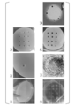
続いて、ハイドロゲル内の自由水を容器の底面部と側面部の間隙より脱水させるとともに上面から乾燥させ、ハイドロゲルの高さが6mmになった時点で製造装置から多孔質のハイドロゲルを取り出し、10℃40%相対湿度で無菌に保たれた恒温恒湿器で乾燥させガラス化させた。図3(a)は、ハイドロゲルから製造装置の側面部を外している状態を示す写真である。図3(b)は、ハイドロゲルから柱状部材を外している状態を示す写真である。図3(c)及び(d)は、製造装置から取り出した多孔質のハイドロゲルの写真である。
続いて、ガラス化後、恒温恒湿器から取り出し、PBS中で再水和させた。更に、新鮮なPBSで再水和による洗浄工程を繰り返し、合計3回洗浄して、製造例1のハイドロゲル膜を得た。図4(a)及び(b)はガラス化後のハイドロゲル乾燥体の写真である。図4(c)は、1回目のPBS添加の洗浄により再水和されたハイドロゲル膜の写真である。図4(d)は、2回目のPBS添加の洗浄により再水和されたハイドロゲル膜の写真である。図4(e)は、3回目のPBS添加の洗浄により再水和されたハイドロゲル膜の写真である。
[製造例2]
底面部と、内径34mmの円筒型の側面部とを有する鋳型を用いて、貫通孔を有するハイドロゲル膜を製造した。貫通孔はトレパンを用いて形成した。まず、鋳型を70%エタノールで滅菌し、クリーンベンチ内で乾燥させた。続いて、製造例1と同様のコラーゲンゾル10mLを鋳型に注入した。続いて、30分間静置後、鋳型を37℃、5%CO2に設定したインキュベーター内に2時間静置してゲル化させ、ハイドロゲルを得た。
底面部と、内径34mmの円筒型の側面部とを有する鋳型を用いて、貫通孔を有するハイドロゲル膜を製造した。貫通孔はトレパンを用いて形成した。まず、鋳型を70%エタノールで滅菌し、クリーンベンチ内で乾燥させた。続いて、製造例1と同様のコラーゲンゾル10mLを鋳型に注入した。続いて、30分間静置後、鋳型を37℃、5%CO2に設定したインキュベーター内に2時間静置してゲル化させ、ハイドロゲルを得た。
続いて、ハイドロゲル内の自由水を鋳型の底面部と側面部の間隙より脱水させるとともに上面から乾燥させ、ハイドロゲルの高さが6mmになった時点で鋳型からハイドロゲルを取り出し、10℃40%相対湿度で無菌に保たれた恒温恒湿器で乾燥させガラス化させた。
続いて、ガラス化後、恒温恒湿器から取り出し、PBS中で再水和させた。更に、新鮮なPBSで再水和による洗浄工程を繰り返し、合計3回洗浄した後、直径2.5mmのトレパンを押し当てて貫通孔を形成することで、製造例2の多孔質のハイドロゲル膜を得た。
[製造例3]
直径1mmのトレパンを用いた点以外は製造例2と同様にして、製造例3の多孔質のハイドロゲル膜を得た。
直径1mmのトレパンを用いた点以外は製造例2と同様にして、製造例3の多孔質のハイドロゲル膜を得た。
[製造例4]
18G(直径1.2mm)の注射針を用いた点以外は製造例2と同様にして、製造例4の多孔質のハイドロゲル膜を得た。
18G(直径1.2mm)の注射針を用いた点以外は製造例2と同様にして、製造例4の多孔質のハイドロゲル膜を得た。
[製造例5]
27G(直径0.4mm)の注射針を用いた点以外は製造例2と同様にして、製造例5の多孔質のハイドロゲル膜を得た。
27G(直径0.4mm)の注射針を用いた点以外は製造例2と同様にして、製造例5の多孔質のハイドロゲル膜を得た。
[製造例6]
底面部と、内径34mmの円筒型の側面部とを有する鋳型を用いて、貫通孔を有するハイドロゲル膜を製造した。貫通孔はトレパンを用いて形成した。まず、鋳型を70%エタノールで滅菌し、クリーンベンチ内で乾燥させた。続いて、製造例1と同様のコラーゲンゾル10mLを鋳型に注入した。続いて、30分間静置後、鋳型を37℃、5%CO2に設定したインキュベーター内に2時間静置してゲル化させ、ハイドロゲルを得た。
底面部と、内径34mmの円筒型の側面部とを有する鋳型を用いて、貫通孔を有するハイドロゲル膜を製造した。貫通孔はトレパンを用いて形成した。まず、鋳型を70%エタノールで滅菌し、クリーンベンチ内で乾燥させた。続いて、製造例1と同様のコラーゲンゾル10mLを鋳型に注入した。続いて、30分間静置後、鋳型を37℃、5%CO2に設定したインキュベーター内に2時間静置してゲル化させ、ハイドロゲルを得た。
続いて、ハイドロゲル内の自由水を鋳型の底面部と側面部の間隙より脱水させるとともに上面から乾燥させ、ハイドロゲルの高さが6mmになった時点で鋳型からハイドロゲルを取り出した。続いて、直径2.5mmのトレパンを押し当てて貫通孔を形成した。図5(a)~(c)は、トレパンを用いてハイドロゲルに貫通孔を形成している様子を撮影した写真である。
続いて、10℃40%相対湿度で無菌に保たれた恒温恒湿器で乾燥させガラス化させた。図5(d)は、ガラス化させたハイドロゲル乾燥体の写真である。また、ガラス化させたハイドロゲル乾燥体の貫通孔を顕微鏡で観察した。図5(e)は貫通孔の顕微鏡写真であり、スケールバーは1mmである。
続いて、ガラス化したハイドロゲル乾燥体を恒温恒湿器から取り出し、PBS中で再水和させた。図5(f)は再水和させたハイドロゲル膜の写真である。また、再水和させたハイドロゲル膜の貫通孔を顕微鏡で観察した。図5(g)は貫通孔の顕微鏡写真であり、スケールバーは1mmである。
更に、新鮮なPBSで再水和による洗浄工程を繰り返し、合計3回洗浄し、製造例6の多孔質のハイドロゲル膜を得た。製造例6のハイドロゲル膜は、製造例2のハイドロゲル膜と、ハイドロゲルをガラス化させる前に貫通孔を形成した点で主に異なっていた。
[製造例7]
ハイドロゲルの高さが10mmになった時点で鋳型からハイドロゲルを取り出さずに直径2.5mmのトレパンを押し当てて貫通孔を形成した点以外は製造例6と同様にして、製造例7の多孔質のハイドロゲル膜を得た。ゲルの高さ10mmに対して、トレパンの刃が7mmと足りなかったため、トレパンをハイドロゲルに押し当てた後、ピンセットでくり抜いて貫通孔を形成した。
ハイドロゲルの高さが10mmになった時点で鋳型からハイドロゲルを取り出さずに直径2.5mmのトレパンを押し当てて貫通孔を形成した点以外は製造例6と同様にして、製造例7の多孔質のハイドロゲル膜を得た。ゲルの高さ10mmに対して、トレパンの刃が7mmと足りなかったため、トレパンをハイドロゲルに押し当てた後、ピンセットでくり抜いて貫通孔を形成した。
[実験例1]
(ハイドロゲル膜の観察)
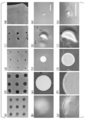
製造例1~5のハイドロゲル膜を観察した。図6(a)、(d)、(g)、(j)、(m)は、それぞれ、製造例1~5のハイドロゲル膜を撮影した写真である。また、図6(b)及び(c)、(e)及び(f)、(h)及び(i)、(k)及び(l)、(n)及び(o)は、それぞれ、製造例1~5のハイドロゲル膜の顕微鏡写真である。図6(b)、(e)、(h)、(k)、(n)の倍率は同じであり、スケールバーは1mmである。また、図6(c)、(f)、(i)、(l)、(o)の倍率は同じであり、スケールバーは1mmである。
(ハイドロゲル膜の観察)
製造例1~5のハイドロゲル膜を観察した。図6(a)、(d)、(g)、(j)、(m)は、それぞれ、製造例1~5のハイドロゲル膜を撮影した写真である。また、図6(b)及び(c)、(e)及び(f)、(h)及び(i)、(k)及び(l)、(n)及び(o)は、それぞれ、製造例1~5のハイドロゲル膜の顕微鏡写真である。図6(b)、(e)、(h)、(k)、(n)の倍率は同じであり、スケールバーは1mmである。また、図6(c)、(f)、(i)、(l)、(o)の倍率は同じであり、スケールバーは1mmである。
製造例1のハイドロゲルの貫通孔が不鮮明に見えるのは、ハイドロゲル膜の一方面における貫通孔の開口面積が、ハイドロゲル膜の他方面における貫通孔の開口面積よりも狭くなっているためである。
[実験例2]
(凹凸面への密着の検討)
製造例1及び製造例2のハイドロゲル膜を凹凸面に密着させ、その様子を観察した。また、比較のために、貫通孔を有していないアテロコラーゲンビトリゲル膜についても同様の検討を行った。
(凹凸面への密着の検討)
製造例1及び製造例2のハイドロゲル膜を凹凸面に密着させ、その様子を観察した。また、比較のために、貫通孔を有していないアテロコラーゲンビトリゲル膜についても同様の検討を行った。
図7(a)は、貫通孔を有していないアテロコラーゲンビトリゲル膜を凹凸面に密着させた結果を示す写真である。図7(b)は、製造例2のハイドロゲル膜を凹凸面に密着させた結果を示す写真である。図7(c)は、製造例1のハイドロゲル膜を凹凸面に密着させた結果を示す写真である。
その結果、貫通孔を有するハイドロゲル膜は、貫通孔を有していないハイドロゲル膜と比較して、凹凸面への密着が良好であることが確認された。
[実験例3]
(液体の透過性の検討)
製造例1及び製造例2のハイドロゲル膜について、液体の透過性を検討した。また、比較のために、貫通孔を有していないアテロコラーゲンビトリゲル膜についても同様の検討を行った。
(液体の透過性の検討)
製造例1及び製造例2のハイドロゲル膜について、液体の透過性を検討した。また、比較のために、貫通孔を有していないアテロコラーゲンビトリゲル膜についても同様の検討を行った。
まず、水を15mLずつ入れた50mLコニカルチューブの口に、貫通孔を有していないアテロコラーゲンビトリゲル膜、製造例1及び製造例2のハイドロゲル膜をそれぞれ被せて乾燥させた。
続いて、ハイドロゲル膜が乾燥した後に、コニカルチューブの口の周囲にパラフィルムを巻き付けて、各ハイドロゲル膜の乾燥体を固定した。続いて、コニカルチューブを反転させて、水がハイドロゲル膜を透過する様子を観察した。図8は、コニカルチューブに各ハイドロゲル膜を被せた様子を示す写真である。
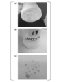
図9(a)は、貫通孔を有していないアテロコラーゲンビトリゲル膜の乾燥体を固定したコニカルチューブを反転させた様子を示す写真である。図9(b)は、反転させたコニカルチューブを厚紙上に接触させた様子を示す写真である。図9(c)は、厚紙上に接触させた結果、水の跡が認められなかった様子を撮影した写真である。その結果、全く水が透過しないことが明らかとなった。
図10は、製造例2のハイドロゲル膜の乾燥体を固定したコニカルチューブを反転させた様子を示す写真である。その結果、水が勢いよく透過する様子が観察された。
図11(a)は、製造例1のハイドロゲル膜の乾燥体を固定したコニカルチューブを反転させた様子を示す写真である。図11(b)は、コニカルチューブを反転状態にしてから約15分後に、反転させたコニカルチューブを厚紙上に接触させた様子を示す写真である。図11(c)は、厚紙上に接触させた結果、水の跡が認められた様子を撮影した写真である。その結果、製造例1のハイドロゲル膜は、液体が徐々に浸みだす程度の液体の透過性を有していることが明らかとなった。
本発明によれば、ハイドロゲル膜を凹凸面に密着させる技術を提供することができる。
100…ハイドロゲル膜、110…一方面、120…他方面、130…貫通孔、200
…製造装置、210…底面部、220…側面部、230…容器部、240…柱状冶具。
…製造装置、210…底面部、220…側面部、230…容器部、240…柱状冶具。
Claims (11)
- 一方面と他方面とを貫通した複数の貫通孔を有する、ハイドロゲル膜。
- 前記貫通孔の前記一方面における開口面積と前記他方面における開口面積が異なっている、請求項1に記載のハイドロゲル膜。
- 前記貫通孔の直径が0.1μm~5mmである、請求項1又は2に記載のハイドロゲル膜。
- 前記貫通孔の密度が1~1,000,000個/cm2である、請求項1又は2に記載のハイドロゲル膜。
- 前記ハイドロゲルが、ネイティブコラーゲン又はアテロコラーゲンを含む、請求項1~4のいずれか一項に記載のハイドロゲル膜。
- 請求項1~5のいずれか一項に記載のハイドロゲル膜の乾燥体。
- 底面部と側面部とを有する容器部と、
前記底面部に接して配置可能な複数の柱状治具と、
を含む、請求項1~5のいずれか一項に記載のハイドロゲル膜又は請求項6に記載のハイドロゲル膜の乾燥体の製造装置。 - 一方面と他方面とを貫通した複数の貫通孔を有するハイドロゲルの製造方法であって、
底面部と側面部とを有する容器部と、前記底面部に接して配置可能な複数の柱状治具と、を含む製造装置の前記容器部にゾルを注入する工程(a)と、
前記ゾルの注入前又は注入後に前記複数の柱状冶具を前記底面部に接するように配置する工程(b)と、
前記ゾルを静置してゲル化し、ハイドロゲルを得る工程(c)と、
前記複数の柱状冶具を除去し、一方面と他方面とを貫通した複数の貫通孔を有するハイドロゲルを得る工程(d)と、を含む、製造方法。 - 一方面と他方面とを貫通した複数の貫通孔を有するハイドロゲルの乾燥体の製造方法であって、請求項8に記載の製造方法により得られたハイドロゲルを乾燥させ、ハイドロゲルの乾燥体を得る工程(e)を含む、製造方法。
- 一方面と他方面とを貫通した複数の貫通孔を有するハイドロゲル膜の製造方法であって、請求項9に記載の製造方法により得られたハイドロゲルの乾燥体を水和させ、水和したハイドロゲル膜を得る工程(f)を含む、製造方法。
- 一方面と他方面とを貫通した複数の貫通孔を有するハイドロゲル膜の乾燥体の製造方法であって、
請求項10に記載の製造方法により得られたハイドロゲル膜を乾燥させ、ハイドロゲル膜の乾燥体を得る工程(e2)を含む、製造方法。
Priority Applications (4)
| Application Number | Priority Date | Filing Date | Title |
|---|---|---|---|
| EP19875491.3A EP3871702A4 (en) | 2018-10-26 | 2019-10-02 | HYDROGEL FILM AND ITS USE |
| US17/274,959 US20220031910A1 (en) | 2018-10-26 | 2019-10-02 | Hydrogel membrane and use thereof |
| KR1020217009685A KR20210086609A (ko) | 2018-10-26 | 2019-10-02 | 하이드로겔막 및 그 사용 |
| CN201980064533.7A CN112789064A (zh) | 2018-10-26 | 2019-10-02 | 水凝胶膜及其使用 |
Applications Claiming Priority (2)
| Application Number | Priority Date | Filing Date | Title |
|---|---|---|---|
| JP2018-201946 | 2018-10-26 | ||
| JP2018201946A JP7290302B2 (ja) | 2018-10-26 | 2018-10-26 | ハイドロゲル膜及びその使用 |
Publications (1)
| Publication Number | Publication Date |
|---|---|
| WO2020085018A1 true WO2020085018A1 (ja) | 2020-04-30 |
Family
ID=70331092
Family Applications (1)
| Application Number | Title | Priority Date | Filing Date |
|---|---|---|---|
| PCT/JP2019/038854 Ceased WO2020085018A1 (ja) | 2018-10-26 | 2019-10-02 | ハイドロゲル膜及びその使用 |
Country Status (6)
| Country | Link |
|---|---|
| US (1) | US20220031910A1 (ja) |
| EP (1) | EP3871702A4 (ja) |
| JP (1) | JP7290302B2 (ja) |
| KR (1) | KR20210086609A (ja) |
| CN (1) | CN112789064A (ja) |
| WO (1) | WO2020085018A1 (ja) |
Citations (8)
| Publication number | Priority date | Publication date | Assignee | Title |
|---|---|---|---|---|
| JPH08243156A (ja) * | 1995-03-07 | 1996-09-24 | Menicon Co Ltd | 培養皮膚およびその製造法 |
| JPH09173362A (ja) * | 1995-12-25 | 1997-07-08 | Menicon Co Ltd | 人工皮膚 |
| WO2005014774A1 (ja) * | 2003-08-11 | 2005-02-17 | National Institute Of Agrobiological Sciences | 動物細胞の培養担体と、該培養担体を用いた動物細胞の培養方法および移植方法 |
| WO2012026531A1 (ja) * | 2010-08-25 | 2012-03-01 | 独立行政法人農業生物資源研究所 | ハイドロゲル乾燥体、ビトリゲル膜乾燥体およびこれらの製造方法 |
| WO2013129465A1 (ja) * | 2012-02-29 | 2013-09-06 | 株式会社ラステック | 医療用多孔プレート |
| WO2017110776A1 (ja) | 2015-12-24 | 2017-06-29 | 国立大学法人 佐賀大学 | 粘膜再生用デバイスおよびこれを利用する粘膜欠損の治療方法 |
| CN107007879A (zh) * | 2017-03-14 | 2017-08-04 | 暨南大学 | 一种活性人工角膜及其制备方法 |
| JP2018201946A (ja) | 2017-06-07 | 2018-12-27 | サミー株式会社 | 遊技機 |
Family Cites Families (13)
| Publication number | Priority date | Publication date | Assignee | Title |
|---|---|---|---|---|
| DE10237531A1 (de) | 2002-08-16 | 2004-02-26 | Tutogen Medical Gmbh | Implantat |
| JPH01170453A (ja) * | 1987-12-25 | 1989-07-05 | Nippon Zeon Co Ltd | 創傷被覆材の製造方法 |
| IT1248934B (it) * | 1990-06-01 | 1995-02-11 | Fidia Spa | Membrane forate biocompatibili,processi per la loro preparazione,loro impiego come supporto per la crescita in vitro di cellule epiteliali, pelli artificiali cosi' ottenute e loro impiego nei trapianti di pelle |
| JPH05192363A (ja) * | 1991-11-07 | 1993-08-03 | Terumo Corp | 創傷被覆材 |
| JPH05337151A (ja) * | 1992-06-11 | 1993-12-21 | Terumo Corp | 創傷被覆材 |
| RU2122842C1 (ru) * | 1996-12-24 | 1998-12-10 | Межотраслевой научно-технический комплекс "Микрохирургия глаза" | Искусственный хрусталик глаза "флоут" |
| GB2377939B (en) | 2001-07-26 | 2005-04-20 | Johnson & Johnson Medical Ltd | Apertured sheet materials |
| JP2004057430A (ja) | 2002-07-29 | 2004-02-26 | Daiya Seiyaku Kk | パッド材及び携帯用パッド材 |
| US20070110962A1 (en) * | 2003-09-23 | 2007-05-17 | Joe Tien | Three-dimensional gels that have microscale features |
| WO2006053291A2 (en) * | 2004-11-09 | 2006-05-18 | Proxy Biomedical Limited | Tissue scaffold |
| US8353967B2 (en) * | 2009-08-10 | 2013-01-15 | Osseous Technologies Of America | Self-supporting collagen tunnel for guided tissue regeneration and method of using same |
| TWI590843B (zh) * | 2011-12-28 | 2017-07-11 | 信迪思有限公司 | 膜及其製造方法 |
| US20170189159A1 (en) * | 2014-06-24 | 2017-07-06 | Osteogenics Biomedical, Inc. | Perforated membrane for guided bone and tissue regeneration |
-
2018
- 2018-10-26 JP JP2018201946A patent/JP7290302B2/ja active Active
-
2019
- 2019-10-02 EP EP19875491.3A patent/EP3871702A4/en not_active Withdrawn
- 2019-10-02 US US17/274,959 patent/US20220031910A1/en not_active Abandoned
- 2019-10-02 KR KR1020217009685A patent/KR20210086609A/ko not_active Withdrawn
- 2019-10-02 WO PCT/JP2019/038854 patent/WO2020085018A1/ja not_active Ceased
- 2019-10-02 CN CN201980064533.7A patent/CN112789064A/zh active Pending
Patent Citations (8)
| Publication number | Priority date | Publication date | Assignee | Title |
|---|---|---|---|---|
| JPH08243156A (ja) * | 1995-03-07 | 1996-09-24 | Menicon Co Ltd | 培養皮膚およびその製造法 |
| JPH09173362A (ja) * | 1995-12-25 | 1997-07-08 | Menicon Co Ltd | 人工皮膚 |
| WO2005014774A1 (ja) * | 2003-08-11 | 2005-02-17 | National Institute Of Agrobiological Sciences | 動物細胞の培養担体と、該培養担体を用いた動物細胞の培養方法および移植方法 |
| WO2012026531A1 (ja) * | 2010-08-25 | 2012-03-01 | 独立行政法人農業生物資源研究所 | ハイドロゲル乾燥体、ビトリゲル膜乾燥体およびこれらの製造方法 |
| WO2013129465A1 (ja) * | 2012-02-29 | 2013-09-06 | 株式会社ラステック | 医療用多孔プレート |
| WO2017110776A1 (ja) | 2015-12-24 | 2017-06-29 | 国立大学法人 佐賀大学 | 粘膜再生用デバイスおよびこれを利用する粘膜欠損の治療方法 |
| CN107007879A (zh) * | 2017-03-14 | 2017-08-04 | 暨南大学 | 一种活性人工角膜及其制备方法 |
| JP2018201946A (ja) | 2017-06-07 | 2018-12-27 | サミー株式会社 | 遊技機 |
Non-Patent Citations (2)
| Title |
|---|
| AOKI S. ET AL.: "High-density collagen patch prevents stricture after endoscopic circumferential submucosal dissection of the esophagus: a porcine model", GASTROINTEST ENDOSC., vol. 85, no. 5, 2017, pages 1076 - 1085, XP029978508, DOI: 10.1016/j.gie.2016.10.012 |
| See also references of EP3871702A4 |
Also Published As
| Publication number | Publication date |
|---|---|
| EP3871702A4 (en) | 2022-07-27 |
| JP7290302B2 (ja) | 2023-06-13 |
| CN112789064A (zh) | 2021-05-11 |
| US20220031910A1 (en) | 2022-02-03 |
| EP3871702A1 (en) | 2021-09-01 |
| JP2020065849A (ja) | 2020-04-30 |
| KR20210086609A (ko) | 2021-07-08 |
Similar Documents
| Publication | Publication Date | Title |
|---|---|---|
| CN101312756B (zh) | 神经导管 | |
| CN105310794B (zh) | 一种内壁具有取向性结构的多孔人工神经导管的制备方法 | |
| JP6031435B2 (ja) | コラーゲン材料、及びコラーゲン材料の製造方法 | |
| ES2960795T3 (es) | Material de reparación de dermis artificial y método de preparación del mismo | |
| CN111317867A (zh) | 一种神经导管及其制备方法 | |
| CN116966345A (zh) | 3d可打印生物凝胶及其使用方法 | |
| CN105999414A (zh) | 制备人造微环境的方法及其应用 | |
| JP6240997B2 (ja) | ガラス化後のハイドロゲル膜の製造方法、ハイドロゲル材料の製造方法、ガラス化後のハイドロゲル膜、ガラス化後のハイドロゲル膜の乾燥体および細胞シート | |
| Guptha et al. | A comprehensive review of the application of 3D-bioprinting in chronic wound management | |
| JP7168937B2 (ja) | 糸及びその製造方法 | |
| CN107708755A (zh) | 利用紫外线的胶原膜的制备方法、利用该方法制备的胶原膜及利用胶原膜制备的生物材料 | |
| CN113350483A (zh) | 一种用于疤痕修复的载白喉毒素的微针及其制备方法 | |
| US20220305177A1 (en) | Thread and method for preparing same | |
| CN105944150B (zh) | 一种水凝胶和应用该水凝胶的人工皮肤及其制备方法 | |
| WO2020085018A1 (ja) | ハイドロゲル膜及びその使用 | |
| JP2023056154A (ja) | コラーゲンスポンジの製造方法およびその製造方法によって製造されたコラーゲンスポンジ | |
| JPS62266064A (ja) | コラ−ゲン膜の製造方法 | |
| JP7344525B2 (ja) | 管状ビトリゲル及びその使用 | |
| JP6993740B2 (ja) | 糸及びその製造方法 | |
| JP7350238B2 (ja) | ハイドロゲル膜乾燥体又はビトリゲル膜乾燥体、その製造装置及びその製造方法、並びに、鼓膜治療デバイス及び創部治療デバイス | |
| JP7019250B2 (ja) | 伸縮性コラーゲンシート | |
| WO2025154731A1 (ja) | 医療材料 | |
| He et al. | High Dense Cell Patches from Acoustically Assisted 3D Bioprinting for Wound Healing | |
| WO2020223480A1 (en) | Systems and methods for magnet-induced assembly of tissue grafts | |
| Lin et al. | Peripheral nerve repair with electrospinning composite conduit |
Legal Events
| Date | Code | Title | Description |
|---|---|---|---|
| 121 | Ep: the epo has been informed by wipo that ep was designated in this application |
Ref document number: 19875491 Country of ref document: EP Kind code of ref document: A1 |
|
| ENP | Entry into the national phase |
Ref document number: 20217009685 Country of ref document: KR Kind code of ref document: A |
|
| NENP | Non-entry into the national phase |
Ref country code: DE |
|
| ENP | Entry into the national phase |
Ref document number: 2019875491 Country of ref document: EP Effective date: 20210526 |