WO2020085055A1 - 自動分析装置 - Google Patents
自動分析装置 Download PDFInfo
- Publication number
- WO2020085055A1 WO2020085055A1 PCT/JP2019/039428 JP2019039428W WO2020085055A1 WO 2020085055 A1 WO2020085055 A1 WO 2020085055A1 JP 2019039428 W JP2019039428 W JP 2019039428W WO 2020085055 A1 WO2020085055 A1 WO 2020085055A1
- Authority
- WO
- WIPO (PCT)
- Prior art keywords
- reagent
- value
- dead volume
- setting
- automatic analyzer
- Prior art date
- Legal status (The legal status is an assumption and is not a legal conclusion. Google has not performed a legal analysis and makes no representation as to the accuracy of the status listed.)
- Ceased
Links
Images


Classifications
-
- G—PHYSICS
- G01—MEASURING; TESTING
- G01N—INVESTIGATING OR ANALYSING MATERIALS BY DETERMINING THEIR CHEMICAL OR PHYSICAL PROPERTIES
- G01N35/00—Automatic analysis not limited to methods or materials provided for in any single one of groups G01N1/00 - G01N33/00; Handling materials therefor
- G01N35/10—Devices for transferring samples or any liquids to, in, or from, the analysis apparatus, e.g. suction devices, injection devices
- G01N35/1009—Characterised by arrangements for controlling the aspiration or dispense of liquids
- G01N35/1016—Control of the volume dispensed or introduced
-
- G—PHYSICS
- G01—MEASURING; TESTING
- G01N—INVESTIGATING OR ANALYSING MATERIALS BY DETERMINING THEIR CHEMICAL OR PHYSICAL PROPERTIES
- G01N35/00—Automatic analysis not limited to methods or materials provided for in any single one of groups G01N1/00 - G01N33/00; Handling materials therefor
- G01N35/00584—Control arrangements for automatic analysers
-
- G—PHYSICS
- G01—MEASURING; TESTING
- G01N—INVESTIGATING OR ANALYSING MATERIALS BY DETERMINING THEIR CHEMICAL OR PHYSICAL PROPERTIES
- G01N35/00—Automatic analysis not limited to methods or materials provided for in any single one of groups G01N1/00 - G01N33/00; Handling materials therefor
- G01N35/02—Automatic analysis not limited to methods or materials provided for in any single one of groups G01N1/00 - G01N33/00; Handling materials therefor using a plurality of sample containers moved by a conveyor system past one or more treatment or analysis stations
- G01N35/025—Automatic analysis not limited to methods or materials provided for in any single one of groups G01N1/00 - G01N33/00; Handling materials therefor using a plurality of sample containers moved by a conveyor system past one or more treatment or analysis stations having a carousel or turntable for reaction cells or cuvettes
-
- G—PHYSICS
- G01—MEASURING; TESTING
- G01N—INVESTIGATING OR ANALYSING MATERIALS BY DETERMINING THEIR CHEMICAL OR PHYSICAL PROPERTIES
- G01N35/00—Automatic analysis not limited to methods or materials provided for in any single one of groups G01N1/00 - G01N33/00; Handling materials therefor
- G01N35/10—Devices for transferring samples or any liquids to, in, or from, the analysis apparatus, e.g. suction devices, injection devices
- G01N35/1002—Reagent dispensers
-
- G—PHYSICS
- G01—MEASURING; TESTING
- G01N—INVESTIGATING OR ANALYSING MATERIALS BY DETERMINING THEIR CHEMICAL OR PHYSICAL PROPERTIES
- G01N35/00—Automatic analysis not limited to methods or materials provided for in any single one of groups G01N1/00 - G01N33/00; Handling materials therefor
- G01N35/00584—Control arrangements for automatic analysers
- G01N35/00594—Quality control, including calibration or testing of components of the analyser
- G01N35/00613—Quality control
- G01N35/00623—Quality control of instruments
- G01N2035/00633—Quality control of instruments logging process history of individual samples
-
- G—PHYSICS
- G01—MEASURING; TESTING
- G01N—INVESTIGATING OR ANALYSING MATERIALS BY DETERMINING THEIR CHEMICAL OR PHYSICAL PROPERTIES
- G01N35/00—Automatic analysis not limited to methods or materials provided for in any single one of groups G01N1/00 - G01N33/00; Handling materials therefor
- G01N35/00584—Control arrangements for automatic analysers
- G01N35/00722—Communications; Identification
- G01N2035/00891—Displaying information to the operator
- G01N2035/0091—GUI [graphical user interfaces]
Definitions
- the present invention relates to an automatic analyzer equipped with a reagent residual amount management mechanism.
- a sample is mixed with a reagent, and the absorbance of the resulting reaction solution is measured to determine the concentration of any substance in the sample. At this time, if the reagent is insufficient, the reaction with the sample becomes insufficient, and an accurate measurement result cannot be obtained.
- Patent Document 2 in order to prevent erroneous detection of the sensor, re-detection is performed or the detection probe position is changed by about 0.1 to 0.2 mm based on the container top height information and the liquid level height information. The technology is described.
- Reagent containers in automatic analyzers have various combinations of materials and shapes.
- many reagent containers have a bottle bottom having a complicated shape so that the reagent in the reagent container can be accurately sucked in a region where the amount of liquid in the reagent container is small.
- the properties of reagents are diverse.
- a phenomenon that the meniscus becomes a convex shape due to the complicated shape of the bottle bottom is observed. This phenomenon can occur especially near the small amount of the reagent liquid in the reagent container.
- Patent Document 2 improves the accuracy of liquid level detection, but it is difficult to determine whether or not the meniscus has a convex shape. Therefore, similar to the technique described in Patent Document 1, liquid The phenomenon in which the actual remaining amount becomes smaller than the estimated remaining amount converted from the height at which the surface is detected does not improve.
- An object of the present invention is to set a measurement item and a threshold value of a reagent remaining amount as a set value of a dead volume, and determine that there is a reagent remaining amount although the reagent remaining amount is actually almost zero. It is an object of the present invention to realize an automatic analyzer capable of avoiding such a situation and suppressing the reagent dispensing failure.
- the present invention is configured as follows.
- a reagent dispensing mechanism that sucks a reagent in a reagent container and dispenses it into a reaction container, an analysis unit that analyzes a sample in the reaction container, and a dead volume setting of the reagent in the reagent container
- the control unit includes a display unit that displays a setting screen for setting a value by an operator, and a control unit that controls the operation of the reagent dispensing mechanism, wherein the control unit sets the reagent in the reagent container on the display screen.
- the reagent distribution is stopped so that the aspiration of the reagent from the reagent container is stopped. Controls the note mechanism.
- a reagent dispensing mechanism that sucks the reagent in the reagent container and dispenses it into the reaction container, an analysis unit that analyzes the sample in the reaction container, and a dead volume of the reagent in the reagent container.
- a display unit for displaying a setting screen having a dead volume setting portion where the operator sets the set value and an automatic mode setting portion where the operator sets the automatic mode; and a dead volume set in the dead volume setting portion.
- a storage unit that stores a set value, and a control unit that controls the operation of the reagent dispensing mechanism, wherein the control unit sets the dead volume in which the reagent in the reagent container is set on the display screen.
- the reagent in the reagent container is less than the set value of the dead volume and the automatic mode is not set, then the reagent is determined. Control the reagent dispensing mechanism to stop the suction of the reagent from the container, the reagent in the reagent container is less than the set value of the dead volume, and, if the automatic mode is set,
- the reagent residual amount information 1 obtained from the number of times of reagent dispensing of the reagent dispensing mechanism and the reagent residual amount information 2 obtained from the liquid level detection value by the liquid level detector mechanism have a difference of a certain amount or more
- a value obtained by adding a change value width to the dead volume set value stored in the storage unit is stored in the storage unit as a dead volume set value, and the reagent dispensing mechanism is configured to stop aspiration of the reagent from the reagent container.
- the measurement item and the threshold value of the reagent remaining amount can be set as the set value of the dead volume, and it is determined that the reagent remaining amount is present although the reagent remaining amount is practically 0. It is possible to realize an automatic analyzer capable of avoiding such a situation and suppressing defective dispensing of reagents.
- Example 1 is an overall schematic configuration diagram of an automatic analyzer to which Example 1 of the present invention is applied. It is explanatory drawing of the reagent dispensing mechanism of the system which detects by the pressure change in a reagent dispensing probe. It is explanatory drawing of the reagent dispensing mechanism of the system which detects by the electrostatic capacitance change between a reagent dispensing probe and ground. It is a figure which shows an example of the screen which a user sets the setting value of dead volume for every measurement item. It is a figure which shows an example of the screen which sets the setting value of the dead volume for every measurement item for every shape of a reagent bottle.
- FIG. 9 is a diagram showing a setting screen for setting a dead volume setting value according to the second embodiment.
- 6 is an operation flowchart of reagent dispensing in the second embodiment.
- FIG. 9 shows the example of the setting screen of a dead volume setting value which defines a setting value as mm instead of a test.
- the reagent remaining amount management system in the vicinity of the minimum liquid amount capable of accurately aspirate the reagent used in the embodiment of the present invention, the dead volume set value of the reagent and the liquid of the reagent are manually or automatically according to the conditions set by the user. It has the function of changing the amount of the reagent probe rushed into the surface and preventing the delay of inspection due to defective reagent dispensing.
- Example 1 An example in which the user (operator) manually sets the management of the reagent remaining amount will be described in the first embodiment.
- Example 1 will be described with reference to FIGS. 1 to 8.
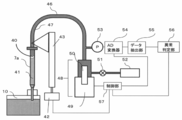
- FIG 1 is an overall schematic configuration diagram of an automatic analyzer to which the first embodiment of the present invention is applied.
- a plurality of reaction vessels 2 for mixing a sample such as blood or urine and a reagent are lined up on the circumference on a reaction disk 1.
- a plurality of reagent bottles (reagent containers) 10 can be placed on the circumference.
- Rotatable and vertically movable reagent dispensing mechanisms 7 and 8 are installed between the reaction disc 1 and the reagent disc 9, and the reagent dispensing mechanisms 7 and 8 include reagent probes 7a and 8a.
- a reagent syringe 18 is connected to the reagent probes 7a and 8a.
- the reagent dispensing mechanisms 7 and 8 suction the reagent from the reagent bottle 10 and dispense (discharge) the reagent into the reaction container 2.
- transfer mechanisms 36 and 37 for moving a sample storage container 16 on which a sample container 15 containing a sample such as a test tube is placed. Between the reaction disk 1 and the transport mechanisms 36 and 37, sample dispensing mechanisms 11 and 35 that can rotate and move up and down are installed, and sample probes 11a and 12a are provided.
- a sample syringe 19 is connected to the sample probes 11a and 12a.
- the sample probes 11a and 12a move while drawing an arc around the rotation axis to suck and discharge the sample from the sample container 15 to the reaction container 2.
- a cleaning mechanism 3, a light source (not shown), a spectrophotometer 4, stirring mechanisms 5 and 6, a reagent disk 9, and transport mechanisms 36 and 37 are arranged around the reaction disk 1, and the cleaning mechanism 3 is for cleaning.
- the pump 20 is connected.
- the washing tanks 13, 14, 30, 31, 32, and 33 are installed on the operating ranges of the reagent dispensing mechanisms 7 and 8, the sample dispensing mechanisms 11 and 35, and the stirring mechanisms 5 and 6, respectively.
- the sample container 15 contains a sample, and the sample container 15 is placed on the sample storage container 16 and is transported by the transport mechanisms 36 and 37.
- Light emitted from a light source (not shown) is applied to the mixed liquid of the sample and the reagent mixed in the reaction container 2.
- the irradiated light is received by the spectrophotometer 4, and the computer 21 for overall management includes an analysis unit 24, and the analysis unit 24 determines the amount of light received by the spectrophotometer 4 (for transmitted light or scattered light of the mixed liquid).
- the concentration of a predetermined component contained in the sample is calculated from the light amount), and the sample is analyzed.
- the reagents used differ depending on the measurement item. In this way, automatic analysis is performed.
- the computer 21 for overall management is provided with a display unit 22 for displaying the analysis result and the setting of the dead volume set value of the reagent, and a storage unit 23 for storing the setting of the automatic analyzer. Further, the overall management computer 21 includes an operation unit for inputting necessary information, a control unit 25 for controlling the reagent dispensing mechanisms 7, 8 and the display unit 22 based on the settings stored in the storage unit 23. (Or is connected).
- the liquid level detection by the liquid level detection mechanism in the reagent bottle 10 is performed by a method of detecting by a pressure change in the reagent dispensing probes 7a, 8a and a capacitance change between the reagent dispensing probes 7a, 8a and the ground. There is a method.
- FIG. 2 is an explanatory view of the reagent dispensing mechanism 7 having a liquid level detection mechanism that detects the liquid level by the pressure change in the reagent dispensing probe 7a
- FIG. It is explanatory drawing of the reagent dispensing mechanism 7 which has a liquid level detection mechanism of the system which detects a liquid level by a change in electric capacity.
- the reagent dispensing mechanism 8 can also have the same configuration as the reagent dispensing mechanism 7.
- the metering pump 48 has a drive mechanism 49 and a plunger 50, and is connected to the pump 52 through a valve 51.
- the metering pump 48 is controlled by the control unit 57 to suck and discharge the reagent.
- the metering pump 48 and the reagent dispensing probe 7a are connected via a dispensing channel 46.
- the pressure sensor 53 is arranged between the plunger 50 and the reagent dispensing probe 7a via the dispensing channel 46, and detects the pressure in the reagent dispensing probe 7a.
- the pressure sensor 53 is connected to the AD converter 54.
- the AD converter 54 digitally converts the analog voltage data output from the pressure sensor 53.
- the data extraction unit 55 receives the digital data of the pressure waveform from the AD converter 54 and delivers it to the abnormality determination unit 56.
- the abnormality determination unit 56 uses the data to determine whether the liquid suction by the reagent dispensing probe 7a is normal or abnormal.
- the determination result of the abnormality determination unit 56 is transmitted to the control unit 57.
- the AD converter 54, the data extraction unit 55, the abnormality determination unit 56, and the control unit 57 can be configured as a part of the overall control computer 21.
- control unit 57 Before sucking the reagent, the control unit 57 opens the valve 51 and fills the inside of the dispensing flow path 46 and the reagent dispensing probe 7a with the system liquid 47 supplied from the pump 52. Next, the control unit 57 causes the drive mechanism 49 to move the plunger 50 downward while the tip of the reagent dispensing probe 7a is in the air, and sucks the segmented air 40.
- the reagent dispensing probe 7a is moved up and down by a reagent probe up-and-down drive mechanism 43 driven by a motor 42.
- the operation of the motor 42 is controlled by the controller 57.
- the control unit 57 lowers the reagent dispensing probe 7a to a predetermined height in the reagent container 10, lowers the plunger 50 by a predetermined amount with the tip immersed in the reagent, and dispenses the reagent into the reagent dispensing probe 7a. Aspirate into. As a result, the reagent as the suction liquid 41 is sucked into the reagent dispensing probe 7a.
- the pressure sensor 53 detects a pressure change in the reagent dispensing probe 7a and determines from the pressure waveform whether or not the probe is in contact with the reagent liquid surface during the suction operation of the probe.
- the pressure sensor 53, the AD converter 54, the data extraction unit 55, and the abnormality determination unit 56 of the example shown in FIG. 2 are not provided.
- the capacitance detection unit 58 that detects the capacitance between the reagent dispensing probe 7a and the ground, and whether the capacitance detected by the capacitance detection unit 58 is abnormal is reversed.
- An abnormality determination unit 59 is provided.
- the control unit 5 detects a change in the capacitance detected by the capacitance detection unit 58 and determines whether or not the reagent dispensing probe 7a has come into contact with the liquid surface of the reagent when the reagent dispensing probe 7a descends.
- the control unit 57, the electrostatic capacitance detection unit 58, and the abnormality determination unit 59 can be configured as a part of the overall control computer 21.
- the present invention may be applied to either the method of detecting the reagent liquid surface by the pressure change shown in FIG. 2 or the method of detecting the reagent liquid surface by the capacitance change shown in FIG.
- the reagent dispensing probe In the method of detecting the reagent liquid surface by the pressure change shown in FIG. 2, the reagent dispensing probe is lowered to a preset height, and whether the reagent liquid surface is reached by the pressure waveform during the suction operation. Determine whether or not.
- the reagent dispensing probe is lowered while detecting the capacitance, and the height at which the change in capacitance is detected is the reagent level. Position.
- the automatic analyzer according to the first embodiment of the present invention has the following reagent remaining amount management function.
- the reagent information such as the reagent name and the remaining amount of the reagent used for the measurement is registered in the storage unit 23 of the computer 21 for overall management.
- the general management computer 21 detects the liquid level by a soft count method of calculating the remaining amount by subtracting the used reagent amount from the reagent amount registered in the storage unit 23 or a sensor or a detection unit attached to the reagent probe 7a, 8a. With this method, the remaining amount of the reagent in the reagent container 10 mounted on the reagent disk 9 is converted into the number of remaining tests and managed.
- the user arbitrarily sets the dead volume setting value according to the measurement item, the shape of the reagent container 10, the wettability of the reagent, and the amount of the device-specific reagent probes 7a and 8a that plunge into the reagent liquid surface. Suggest a method.
- the overall management computer 21 ends the suction from the reagent bottle 10.
- the dead volume in the present specification refers to the minimum amount of liquid in the reagent container 10 that can accurately aspirate the reagent, and the set value of the dead volume is a value set by the user as the dead volume. is there.
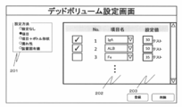
- FIG. 4 is a diagram showing an example of a screen on which the user sets a dead volume setting value for each measurement item.
- the dead volume setting screen shown in FIG. 4 is displayed on the display unit 22 (the dead volume setting screens in the examples of FIGS. 5 and 6 described later are also displayed on the display unit 22).
- the dead volume setting value is set using the keyboard, mouse, etc., which is the operation unit, on the setting screen (dead volume setting screen) of the reagent remaining amount management method displayed on the screen.
- This setting screen displays a setting method selection part 201 for selecting a setting method and an application condition setting part 202 for setting conditions for applying the setting.
- the applicable condition setting part (measurement item name setting part) 202 has a column for selecting an arbitrary measurement item set by the user.
- the dead volume setting value setting part 203 for setting the dead volume setting value is a part where the user can set an arbitrary dead volume setting value.
- a check box may be provided to facilitate switching of settings. In the screen example of FIG. 4, three check boxes are displayed on the left side of the applicable condition setting part 202, and two check boxes are checked.
- the setting No. that the setting is valid.
- the setting No. The second measurement item ALB is set to end the measurement from the reagent bottle 10 in use when the remaining 50 tests fall.
- the check box is not checked, that is, the setting is invalid. Therefore, instead of the 35 tests on the screen display, according to the number of remaining tests set by default, from the reagent bottle 10 in use, It is set to end the measurement by suctioning the reagent.
- the number of remaining tests set by default is, for example, 10 tests.
- the user can arbitrarily set the measurement items from the dead volume setting value setting screen shown in FIG. 4, so that it is possible to manage the reagent remaining amount near the dead volume only for the measurement items that need to be set. As a result, it is possible to efficiently take measures against reagent dispensing failure, including operation of reagents.
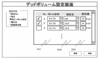
- FIG. 5 is a diagram showing an example of a screen for setting a dead volume set value for each measurement item for each bottle shape (container shape) of the reagent bottle 10.
- the remaining amount management method can be set by the combination of the reagent bottle shape and the measurement item.
- the bottle shape setting part (container shape setting part) 301 of the reagent container 10 the measurement item having the specified bottle shape is stored in the measurement item name setting part 302 from the application information registered by the user. Will be picked up.
- a check box similar to that shown in FIG. 4 may be provided to facilitate switching of settings.
- the measurement item IgA of the bottle shape type A of No. 1 is less than the remaining 30 tests as shown in the dead volume value setting portion 303, the setting No.
- the remaining measurement item ALB of the bottle shape type B of 2 is less than the remaining 50 tests, the measurement by the reagent suction from the reagent bottle 10 in use is completed.
- the check box is not checked. That is, since the setting is invalid, the measurement from the reagent bottle 10 in use is ended according to the number of remaining tests set by default instead of the 50 tests on the screen display.
- the number of remaining tests set by default is, for example, 10 tests.
- the user can arbitrarily set the bottle shape and the measurement item in advance, so that the reagent remaining amount near the dead volume can be managed only for the bottle shape and the measurement item that need to be set. it can.
- the dead volume set value setting portion 303 allows the user to set an arbitrary dead volume set value.
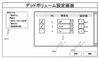
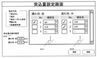
- FIG. 6 is a diagram showing an example of a screen for setting a dead volume set value for each wettability of a reagent.
- the user has two groups of a low wettability display portion 401 showing “wetness: low” of the reagent and a middle wettability display portion 402 showing “wettability: medium” of the reagent. Can be set for any measurement item.
- the low wettability display portion 401 and the middle wettability display portion 402 are collectively referred to as the wettability display portion of the reagent.
- the same check boxes as shown in FIGS. 4 and 5 may be provided to facilitate switching of settings.
- the dead volume set value of the dead volume set value setting portion 403 is 50 tests
- the dead volume set value of the “wetness: medium” measurement item is 30 tests. Is set to.
- the measurement item IgA of No. 1 has the remaining 50 tests according to the “wetting property: low” setting, and the setting No. of the measuring item “wetting property: medium”.
- Measurement item CRE of No. 1 and No. 1 When the second measurement item CRP falls below the remaining 30 tests, the measurement from the reagent bottle 10 in use is terminated.
- the user can set the dead volume setting value for each group within the range specified by the manufacturer.
- the setting value of the target group can be changed in a batch, so that the time required for the operator to set can be further saved.
- the reagent dead volume setting value in the reagent bottle 10 there is a setting by a device-specific value.
- the device-specific value is a value that is set depending on the amount of the reagent dispensing probes 7a and 8a that plunge from the liquid surface of the reagent.
- the plunge amount setting part is displayed, and the operator sets the dead volume set value for each plunging amount from the reagent liquid surface of the reagent dispensing mechanism 7, 8. It is configurable to allow. Since the setting is applied to all the measurement items, the operator can save the labor as compared with other options in setting the dead volume setting value.
- the settings of these dead volume setting values are stored in the storage unit 23 of the general management computer 21. Since the user can select the method of setting the dead volume setting value that suits the operating environment from the viewpoint of workability and the amount of waste reagent, the first embodiment of the present invention can be applied to various usage scenes.
- the dead volume setting value may be selected by the user from a plurality of recommended values. Further, on the dead volume setting screen, the user may select only the setting method and the applicable range of the setting, and the fixed volume set by the manufacturer may be used as the set value of the dead volume with the setting.
- FIG. 7 is an operation flowchart of reagent dispensing in the first embodiment. The operation flow shown in FIG. 7 is performed under the control of the general management computer 21 for each measurement item.
- step 501 analysis is started (step 501), and the reagent is dispensed by the reagent dispensing probe 7a or 8a (step 502).
- step 503 it is confirmed in the storage unit 23 whether the dead volume set value is set (step 503).
- step 503 when the dead volume set value is not set in the storage unit 23, the reagent in the reagent bottle 10 is equal to or more than the default set value of the dead volume by the management by the liquid level sensor (liquid level detection mechanism) or the soft count described above. It is determined whether there is any (step 504).
- step 504 If it is determined in step 504 that the reagent in the reagent bottle 10 is equal to or greater than the default setting value of the dead volume, the process proceeds to the measurement of the next sample (step 506).
- step 504 when the reagent in the reagent bottle 10 is less than the default setting value of the dead volume, the reagent dispensing mechanisms 7 and 8 are controlled so as to stop the suction operation of the reagent from the reagent bottle 10 and the reagent concerned.
- the measurement with the reagent in the bottle 10 is completed (step 507), the reagent container is replaced with the next reagent container, and the measurement is continued.
- step 503 it is determined by the above-described liquid level sensor or soft count management whether the remaining amount of the reagent in the reagent bottle 10 is the dead volume set value or more (step 505).
- step 505 If the remaining amount of the reagent in the reagent bottle 10 is equal to or greater than the set value of the dead volume in step 505, the process proceeds to the measurement of the next sample (step 508).
- step 505 when the remaining amount of the reagent in the reagent bottle 10 is less than the set value of the dead volume, the reagent dispensing mechanisms 7 and 8 are controlled so as to stop the suction operation of the reagent from the reagent bottle 10, and the reagent is dispensed.
- the measurement with the reagent of the bottle 10 is completed, the use of the reagent bottle 10 is finished (step 507), the reagent bottle 10 is replaced with the next reagent bottle 10, and the measurement is continued.
- FIG. 8 is a diagram showing a confirmation screen (displayed on the display unit 22) for confirming whether the condition, the remaining amount of the reagent, and the dead volume set value are set for each measurement item.
- the confirmation screen includes a reagent position display portion 601, a measurement item name display portion 602, a usage status display portion 603 for displaying whether the reagent is in use or a standby state, a reagent remaining test number display portion 604, and the like.
- the dead volume setting display part 605 is displayed.
- the dead volume setting display area 605 it is possible to confirm whether the dead volume setting value is not set or is set, and if it is set, which setting is selected is displayed. This allows the user to know whether unnecessary settings have been made.
- the user can previously set and set the dead volume set value of the reagent in the reagent bottle 10 for each measurement item, bottle shape, and wettability of the reagent. Since the reagent dispensing operation is controlled according to the dead volume set value (threshold value), it is determined that the remaining amount is present although the remaining amount is actually almost zero. It is possible to realize an automatic analyzer capable of avoiding the situation that occurs, preventing reagent dispensing failure, and performing efficient reagent operation.
- Example 2 is an example in which the device automatically changes the dead volume setting value. Since the automatic analyzer to which the second embodiment is applied is the same as that of the first embodiment, illustration and detailed description thereof are omitted.
- Example 2 will be described with reference to FIGS. 9 and 10.
- the automatic analyzer has a system for judging whether or not the amount of the reagent is reduced by one test per use of the reagent by the liquid level detection of the reagent in the reagent bottle 10 by the liquid level detection mechanism and the soft count.
- the corrected dead volume set value is stored in the storage unit of the entire computer 21 of the automatic analyzer. 23.
- FIG. 9 is a diagram showing a dead volume setting screen in the second embodiment.
- the dead volume setting screen has an automatic mode setting button (automatic mode setting part) 701 such as a check box for switching the automatic mode.
- the automatic mode setting button 701 may be arranged on the screen of the first embodiment. Further, in order to reduce the risk of reagent dispensing failure that occurs immediately before the remaining amount of the reagent near the dead volume becomes 0 test, it is possible to set Example 1 and Example 2 at the same time. Using the dead volume setting value set by the method 1 as a reference, according to the flow of the second embodiment, the dead volume installation value is changed according to a preset value when a certain condition is satisfied.
- the configuration is such that the setting part of the dead volume setting value is displayed like the setting screen shown in FIGS. 4, 5 or 6 in the first embodiment. it can.
- FIG. 10 is an operation flowchart of reagent dispensing in the second embodiment.
- step 801 after the analysis is started (step 801), reagent dispensing is performed (step 802), and at this time, the overall management computer 21 manages the liquid level sensor or the soft count so that the reagent remaining in the reagent bottle 10 remains. It is confirmed whether or not the amount is equal to or less than the set dead volume setting value (step 803). When the remaining amount of the reagent in the reagent bottle 10 is larger than the dead volume set value in step 803, the process returns to step 802, and the reagent of the reagent bottle 10 is used when the use of the reagent is requested in the next measurement. To be done.
- step 803 If the remaining amount of the reagent in the reagent bottle 10 is less than or equal to the dead volume set value in step 803, it is confirmed whether or not the automatic mode is set for the dead volume (step 804).
- the automatic mode is not set for the dead volume in step 804, the measurement from the reagent bottle 10 is completed and the dead volume set value is not changed (step 808).
- step 804 when the automatic mode is set, the dead volume setting is performed from the test number in which the reagent in the reagent bottle 10 is preset to the dead volume setting value and the remaining test number (for example, 30 tests) is added.
- the remaining test number for example, 30 tests
- the number of remaining tests obtained from the liquid level detection value by the liquid level sensor (reagent remaining amount information 1) and the remaining test number calculated by soft count (reagent remaining amount information 2) are compared with each other, and it is determined whether or not there is a difference of a certain amount or more (whether or not there is a remaining amount skip) based on the information stored in the storage unit 23 (step 805).
- step 805 if there is no difference between the remaining test number obtained from the liquid level detection by the liquid level sensor and the remaining test number calculated by the soft count, that is, if there is no remaining amount skip, the inside of the reagent bottle 10 The measurement by the reagent dispensing is completed, and the dead volume setting value is not changed (step 809).
- step 805 when the difference in the remaining test number occurs in the reagent in the reagent bottle 10 and the remaining test number obtained from the liquid level detection by the sensor is larger than the remaining test number calculated by the soft count by a certain amount or more. That is, when the remaining amount is skipped, the dead volume setting value of this type of reagent is changed by adding a +5 test (change width value) to the current setting value (step 806), and the changed information is stored in the storage unit 23. Store in. Then, the measurement by dispensing the reagent in the reagent bottle 10 is completed (step 807).
- the dead volume setting value since the dead volume setting value is automatically changed, the user can save the trouble of manual setting (changing the dead volume setting value). Further, when it is not desired to increase the amount of discarded reagent beyond a certain line, the upper limit value for changing the dead volume may be set. It is also possible to change the change width value of this dead volume from the +5 test to another value. This can be changed by the dead volume change width setting portion 702 shown in FIG. By operating this dead volume change width setting portion 702, the current dead volume change upper limit value is displayed on the dead volume change width setting portion 702, and the displayed value can be changed.
- the same effect as that of the first embodiment can be obtained, and the number of remaining tests and soft count obtained from the liquid level detection by the liquid level detection mechanism (liquid level sensor) near the dead volume set value. Even if there is a discrepancy between the remaining test number calculated by (counting (counting) the reagent dispensing times of the reagent dispensing mechanisms 7 and 8 by the control unit 25), that is, when the remaining amount is skipped, the automatic Since the dead volume set value can be changed to an appropriate value, the user does not need to manually change the dead volume set value, and the work load on the user (operator) can be reduced.
- step 805 the set value of the number of tests for determining the presence / absence of remaining amount skip is not limited to 30 tests, and the user may arbitrarily change it.
- the remaining amount of the reagent may be managed and set not by the number of tests but by the volume of the reagent or the liquid level height.
- changing the dead volume setting has been described as an example of means for solving the problem.
- the amount of the reagent dispensing probes 7a and 8a that plunge into the liquid surface in the reagent bottle 10 may be changed.
- the plunge amount setting portions 204 (FIG. 12), 304 (FIG. 13), and 404 (FIG. 14) are displayed, and each measurement item, each reagent container shape, and each reagent wettability is displayed.
- the amount of the reagent dispensing probe that plunges into the liquid surface may be set. Further, the amount of plunge may be set together with the dead volume setting value.
- the amount of protrusion to the liquid surface in the reagent bottle 10 may be set to be increased by 0.01 mm.
- the user sets the value within the range specified by the manufacturer, such as 0 to 0.3 mm.
- Analysis unit 36, 37 ... Transport mechanism, 40 ... Segment air, 41 ... Aspirate, 42 ... Motor, 43 ... Reagent probe vertical drive mechanism, 46 ... Dispensing flow path, 4 ... system liquid, 48 ... metering pump, 49 ... drive mechanism, 50 ... plunger, 51 ... valve, 52 ... pump, 53 ... pressure sensor, 54 ... AD Converter, 55 ... Data extraction section, 56, 59 ... Abnormality determination section, 57 ... Control section, 58 ... Capacitance detection section, 201 ... Setting method selection section site, 202 ... ..Applied condition setting part, 203, 303, 403 ... Dead volume value setting part, 204, 304, 404 ...
- Plunge amount setting part 301 ... Bottle shape setting part, 302 ... Measurement item name Setting site, 401, 402 ... Low wettability display site, 601 ... Reagent position display site, 602 ... Measurement item name display site, 603 ... Usage status display site, 604 ... Reagent Remaining test count display area, 60 ... dead volume setting display site, 701 ... automatic mode setting button, 702 ... dead volume change width set-up site
Landscapes
- Chemical & Material Sciences (AREA)
- Physics & Mathematics (AREA)
- Health & Medical Sciences (AREA)
- Life Sciences & Earth Sciences (AREA)
- Analytical Chemistry (AREA)
- Biochemistry (AREA)
- General Health & Medical Sciences (AREA)
- General Physics & Mathematics (AREA)
- Immunology (AREA)
- Pathology (AREA)
- Chemical Kinetics & Catalysis (AREA)
- Automatic Analysis And Handling Materials Therefor (AREA)
Abstract
Description
試薬残量の管理の設定をユーザー(操作者)がマニュアルで行う例を実施例1で説明する。実施例1について、図1~図8を参照して説明する。
次に、本発明の実施例2について説明する。
Claims (15)
- 試薬容器内の試薬を吸引し、反応容器に分注する試薬分注機構と、
前記反応容器内の試料を分析する分析部と、
前記試薬容器内の試薬のデッドボリューム設定値の値を操作者が設定する設定画面を表示する表示部と、
前記試薬分注機構の動作を制御する制御部と、
を備え、前記制御部は、前記試薬容器内の試薬が前記表示画面に設定された前記デッドボリューム設置値の値以上か否かを判定し、前記試薬容器内の試薬が前記デッドボリューム設定値未満であれば、当該試薬容器からの試薬の吸引を停止するように前記試薬分注機構を制御することを特徴とする自動分析装置。 - 請求項1に記載の自動分析装置において、
前記設定画面は、前記操作者が測定項目別に前記デッドボリューム設定値を設定する測定項目名設定部位を表示することを特徴とする自動分析装置。 - 請求項2に記載の自動分析装置において、
前記設定画面は、前記操作者が、容器形状毎に測定項目別で前記デッドボリューム設定値の値を設定する容器形状設定部位を表示することを特徴とする自動分析装置。 - 請求項1に記載の自動分析装置において、
前記設定画面は、前記操作者が、前記試薬の濡れ性別に前記デッドボリューム設定値の値を設定する試薬の濡れ性表示部位を表示することを特徴とする自動分析装置。 - 請求項1に記載の自動分析装置において、
前記設定画面は、前記操作者が、測定項目別に前記試薬分注機構の前記試薬の液面への突込量の値を設定する突込量設定部位を表示することを特徴とする自動分析装置。 - 請求項5に記載の自動分析装置において、
前記設定画面は、前記操作者が、容器形状毎に前記試薬分注機構の前記試薬の液面への突込量の値を設定する突込量設定部位を表示することを特徴とする自動分析装置。 - 請求項5に記載の自動分析装置において、
前記設定画面は、前記操作者が、前記試薬の濡れ性別に前記試薬分注機構の前記試薬の液面への突込量の値を設定する突込量設定部位を表示することを特徴とする自動分析装置。 - 請求項1、2、3、4、5のうちのいずれか一項に記載の自動分析装置において、
前記試薬の液面を検知する液面検知機構を備えることを特徴とする自動分析装置。 - 試薬容器内の試薬を吸引し、反応容器に分注する試薬分注機構と、
前記反応容器内の試料を分析する分析部と、
前記試薬容器内の試薬のデッドボリューム設定値の値を操作者が設定するデッドボリューム設定部位及び前記操作者が自動モードを設定する自動モード設定部位を有する設定画面を表示する表示部と、
分析に必要な設定値の値を記憶する記憶部と、
前記試薬分注機構の動作を制御する制御部と、
を備え、前記制御部は、前記試薬容器内の試薬が前記表示画面に設定された前記デッドボリューム設定値の値以下か否かを判定し、前記試薬容器内の試薬が前記デッドボリューム設定値以下であり、かつ、前記自動モードが設定されていない場合は、当該試薬容器からの試薬の吸引を停止するように前記試薬分注機構を制御し、
前記試薬容器内の試薬が前記デッドボリューム設定値以下であり、かつ、前記自動モードが設定されている場合は、
前記デットボリューム設定値に所定のテスト数を加えた残テスト数から、前記デットボリューム設定値までの間に、前記試薬分注機構の試薬分注回数から得られる試薬残量情報1と前記液面検知器機構による液面検知値から得られた試薬残量情報2とに一定以上の乖離があったか否かを判定し、一定以上の乖離があった場合には、前記記憶部に記憶された前記デッドボリューム設定値に変更値幅を加算した値をデッドボリューム設定値として前記記憶部に記憶し、当該試薬容器からの試薬の吸引を停止するように前記試薬分注機構を制御することを特徴とする自動分析装置。 - 請求項7に記載の自動分析装置において、
前記設定画面は、前記操作者が測定項目別に前記デッドボリューム設定値を設定する測定項目名設定部位を表示することを特徴とする自動分析装置。 - 請求項8に記載の自動分析装置において、
前記設定画面は、前記操作者が、容器形状毎に測定項目別で前記デッドボリューム設定値の値を設定する容器形状設定部位を表示することを特徴とする自動分析装置。 - 請求項7に記載の自動分析装置において、
前記設定画面は、前記操作者が、前記試薬の濡れ性別に前記デッドボリューム設定値の値を設定する試薬の濡れ性表示部位を表示することを特徴とする自動分析装置。 - 請求項9に記載の自動分析装置において、
前記設定画面は、前記操作者が、測定項目別に前記試薬分注機構の前記試薬の液面への突込量の値を設定する突込量設定部位を表示することを特徴とする自動分析装置。 - 請求項13に記載の自動分析装置において、
前記設定画面は、前記操作者が、容器形状毎に前記試薬分注機構の前記試薬の液面への突込量の値を設定する突込量設定部位を表示することを特徴とする自動分析装置。 - 請求項14に記載の自動分析装置において、
前記設定画面は、前記操作者が、前記試薬の濡れ性別に前記試薬分注機構の前記試薬の液面への突込量の値を設定する突込量設定部位を表示することを特徴とする自動分析装置。
Priority Applications (4)
| Application Number | Priority Date | Filing Date | Title |
|---|---|---|---|
| EP19876433.4A EP3872496B1 (en) | 2018-10-26 | 2019-10-07 | Automated analyzer |
| US17/277,417 US12228585B2 (en) | 2018-10-26 | 2019-10-07 | Automatic analyzer |
| CN201980057145.6A CN112639481A (zh) | 2018-10-26 | 2019-10-07 | 自动分析装置 |
| JP2020553076A JP7061686B2 (ja) | 2018-10-26 | 2019-10-07 | 自動分析装置 |
Applications Claiming Priority (2)
| Application Number | Priority Date | Filing Date | Title |
|---|---|---|---|
| JP2018201395 | 2018-10-26 | ||
| JP2018-201395 | 2018-10-26 |
Publications (1)
| Publication Number | Publication Date |
|---|---|
| WO2020085055A1 true WO2020085055A1 (ja) | 2020-04-30 |
Family
ID=70331069
Family Applications (1)
| Application Number | Title | Priority Date | Filing Date |
|---|---|---|---|
| PCT/JP2019/039428 Ceased WO2020085055A1 (ja) | 2018-10-26 | 2019-10-07 | 自動分析装置 |
Country Status (5)
| Country | Link |
|---|---|
| US (1) | US12228585B2 (ja) |
| EP (1) | EP3872496B1 (ja) |
| JP (1) | JP7061686B2 (ja) |
| CN (1) | CN112639481A (ja) |
| WO (1) | WO2020085055A1 (ja) |
Families Citing this family (4)
| Publication number | Priority date | Publication date | Assignee | Title |
|---|---|---|---|---|
| JP7417463B2 (ja) * | 2020-04-24 | 2024-01-18 | 株式会社日立ハイテク | 分注装置、自動分析装置、分注方法 |
| US20220268796A1 (en) * | 2021-02-19 | 2022-08-25 | Roche Molecular Systems, Inc. | Method of Operating a Laboratory Instrument |
| CN118829885A (zh) * | 2022-03-10 | 2024-10-22 | 株式会社日立高新技术 | 分注装置及自动分析装置 |
| CN116465709B (zh) * | 2023-04-19 | 2023-12-29 | 杭州海世嘉生物科技有限公司 | 一种全自动免疫组化染色机控制方法、系统及存储介质 |
Citations (12)
| Publication number | Priority date | Publication date | Assignee | Title |
|---|---|---|---|---|
| JPH11132830A (ja) | 1997-11-04 | 1999-05-21 | Olympus Optical Co Ltd | 超音波液面検知装置及びこの装置を用いた液面検知方法 |
| JPH11316239A (ja) * | 1998-05-01 | 1999-11-16 | Shimadzu Corp | 自動化学分析装置 |
| JP2002098706A (ja) * | 2000-09-22 | 2002-04-05 | Fuji Photo Film Co Ltd | 定量吸引チップおよび定量吸引装置 |
| JP2002350454A (ja) | 2001-05-30 | 2002-12-04 | Aloka Co Ltd | 分注装置 |
| JP2007322241A (ja) * | 2006-05-31 | 2007-12-13 | Olympus Corp | 自動分析装置 |
| JP2009036512A (ja) * | 2007-07-31 | 2009-02-19 | Hitachi High-Technologies Corp | 自動分析装置 |
| JP2009180605A (ja) * | 2008-01-30 | 2009-08-13 | Olympus Corp | 分注装置 |
| JP2010139485A (ja) * | 2008-12-15 | 2010-06-24 | Toshiba Corp | 自動分析装置 |
| JP2012117953A (ja) * | 2010-12-02 | 2012-06-21 | Toshiba Corp | 自動分析装置および試薬容器保管装置 |
| JP2014145677A (ja) * | 2013-01-29 | 2014-08-14 | Hitachi High-Technologies Corp | 自動分析装置 |
| JP2017129393A (ja) * | 2016-01-19 | 2017-07-27 | 日本電子株式会社 | 自動分析装置及び自動分析方法 |
| WO2018051672A1 (ja) * | 2016-09-16 | 2018-03-22 | 株式会社 日立ハイテクノロジーズ | 自動分析装置および自動分析システム並びに試薬リストの表示方法 |
Family Cites Families (8)
| Publication number | Priority date | Publication date | Assignee | Title |
|---|---|---|---|---|
| JP3156550B2 (ja) * | 1995-07-11 | 2001-04-16 | 株式会社日立製作所 | 試薬管理の方法および装置 |
| FR2777086B3 (fr) * | 1998-04-01 | 2000-06-09 | Bio Merieux | Procede de prelevement et de detection de surface d'un echantillon biologique par l'intermediaire d'un appareil d'aspiration-refoulement |
| CN101233233A (zh) * | 2005-08-30 | 2008-07-30 | 富士胶片株式会社 | 分离和纯化rna的方法 |
| JP4851267B2 (ja) * | 2006-08-18 | 2012-01-11 | シスメックス株式会社 | 試料分析装置 |
| JP4916328B2 (ja) * | 2007-02-02 | 2012-04-11 | ベックマン コールター, インコーポレイテッド | 自動分析装置 |
| JP4538477B2 (ja) * | 2007-08-31 | 2010-09-08 | 株式会社日立ハイテクノロジーズ | 自動分析装置 |
| CN103162770B (zh) * | 2013-04-02 | 2017-02-22 | 常州市微凯医疗科技有限公司 | 用于免疫组化染色机的微量试剂液面检测方法及装置 |
| CN107533079B (zh) * | 2015-04-24 | 2021-06-29 | 株式会社日立高新技术 | 自动分析装置及方法 |
-
2019
- 2019-10-07 JP JP2020553076A patent/JP7061686B2/ja active Active
- 2019-10-07 WO PCT/JP2019/039428 patent/WO2020085055A1/ja not_active Ceased
- 2019-10-07 EP EP19876433.4A patent/EP3872496B1/en active Active
- 2019-10-07 US US17/277,417 patent/US12228585B2/en active Active
- 2019-10-07 CN CN201980057145.6A patent/CN112639481A/zh active Pending
Patent Citations (12)
| Publication number | Priority date | Publication date | Assignee | Title |
|---|---|---|---|---|
| JPH11132830A (ja) | 1997-11-04 | 1999-05-21 | Olympus Optical Co Ltd | 超音波液面検知装置及びこの装置を用いた液面検知方法 |
| JPH11316239A (ja) * | 1998-05-01 | 1999-11-16 | Shimadzu Corp | 自動化学分析装置 |
| JP2002098706A (ja) * | 2000-09-22 | 2002-04-05 | Fuji Photo Film Co Ltd | 定量吸引チップおよび定量吸引装置 |
| JP2002350454A (ja) | 2001-05-30 | 2002-12-04 | Aloka Co Ltd | 分注装置 |
| JP2007322241A (ja) * | 2006-05-31 | 2007-12-13 | Olympus Corp | 自動分析装置 |
| JP2009036512A (ja) * | 2007-07-31 | 2009-02-19 | Hitachi High-Technologies Corp | 自動分析装置 |
| JP2009180605A (ja) * | 2008-01-30 | 2009-08-13 | Olympus Corp | 分注装置 |
| JP2010139485A (ja) * | 2008-12-15 | 2010-06-24 | Toshiba Corp | 自動分析装置 |
| JP2012117953A (ja) * | 2010-12-02 | 2012-06-21 | Toshiba Corp | 自動分析装置および試薬容器保管装置 |
| JP2014145677A (ja) * | 2013-01-29 | 2014-08-14 | Hitachi High-Technologies Corp | 自動分析装置 |
| JP2017129393A (ja) * | 2016-01-19 | 2017-07-27 | 日本電子株式会社 | 自動分析装置及び自動分析方法 |
| WO2018051672A1 (ja) * | 2016-09-16 | 2018-03-22 | 株式会社 日立ハイテクノロジーズ | 自動分析装置および自動分析システム並びに試薬リストの表示方法 |
Non-Patent Citations (1)
| Title |
|---|
| See also references of EP3872496A4 |
Also Published As
| Publication number | Publication date |
|---|---|
| JP7061686B2 (ja) | 2022-04-28 |
| CN112639481A (zh) | 2021-04-09 |
| US12228585B2 (en) | 2025-02-18 |
| JPWO2020085055A1 (ja) | 2021-09-02 |
| EP3872496B1 (en) | 2025-07-23 |
| EP3872496A1 (en) | 2021-09-01 |
| US20220034930A1 (en) | 2022-02-03 |
| EP3872496A4 (en) | 2022-08-03 |
Similar Documents
| Publication | Publication Date | Title |
|---|---|---|
| JP7061686B2 (ja) | 自動分析装置 | |
| JP5736280B2 (ja) | 自動分析装置 | |
| US20130064737A1 (en) | Automatic analyzer | |
| EP2878955B1 (en) | Automated analyzer | |
| US9052300B2 (en) | Methods, systems, and apparatus to determine a clot carryout condition upon probe retraction during sample aspiration and dispensing | |
| JP7455142B2 (ja) | 自動分析装置 | |
| JP2010071765A (ja) | 分注プローブ洗浄方法および自動分析装置 | |
| JP2004271266A (ja) | 分注装置およびそれを用いた自動分析装置 | |
| JP2018194301A (ja) | 自動分析装置、及び洗浄液量の調整方法 | |
| JP2010071766A (ja) | 分注装置、自動分析装置および分注不良確認方法 | |
| JP6919535B2 (ja) | 分注装置 | |
| US10514387B2 (en) | Method for monitoring the functionality of a wash station for pipetting needles | |
| US20190369130A1 (en) | Automatic Analyzer | |
| EP4350358A1 (en) | Automatic analysis device | |
| CN118401842A (zh) | 自动分析装置、分注方法 | |
| JP7167037B2 (ja) | 自動分析装置および検体分注機構の異常検出方法 | |
| JP2007327779A (ja) | 自動分析装置および自動分析装置の分注精度確認方法 | |
| JP2012137436A (ja) | 自動分析装置 | |
| JP2024008589A (ja) | 自動分析装置 | |
| JP6333550B2 (ja) | 自動分析装置 | |
| JP5388745B2 (ja) | 自動分析装置 | |
| WO2010150502A1 (ja) | 自動分析装置 | |
| JP2012189514A (ja) | 自動分析装置 | |
| JP2025035764A (ja) | 撹拌プローブ及び撹拌装置 | |
| WO2024034381A1 (ja) | 自動分析装置および洗浄液量の調整方法 |
Legal Events
| Date | Code | Title | Description |
|---|---|---|---|
| 121 | Ep: the epo has been informed by wipo that ep was designated in this application |
Ref document number: 19876433 Country of ref document: EP Kind code of ref document: A1 |
|
| ENP | Entry into the national phase |
Ref document number: 2020553076 Country of ref document: JP Kind code of ref document: A |
|
| NENP | Non-entry into the national phase |
Ref country code: DE |
|
| ENP | Entry into the national phase |
Ref document number: 2019876433 Country of ref document: EP Effective date: 20210526 |
|
| WWG | Wipo information: grant in national office |
Ref document number: 2019876433 Country of ref document: EP |