WO2020085401A1 - Dispositif de connecteur coaxial - Google Patents
Dispositif de connecteur coaxial Download PDFInfo
- Publication number
- WO2020085401A1 WO2020085401A1 PCT/JP2019/041572 JP2019041572W WO2020085401A1 WO 2020085401 A1 WO2020085401 A1 WO 2020085401A1 JP 2019041572 W JP2019041572 W JP 2019041572W WO 2020085401 A1 WO2020085401 A1 WO 2020085401A1
- Authority
- WO
- WIPO (PCT)
- Prior art keywords
- contact member
- connector device
- signal
- coaxial connector
- coaxial
- Prior art date
- Legal status (The legal status is an assumption and is not a legal conclusion. Google has not performed a legal analysis and makes no representation as to the accuracy of the status listed.)
- Ceased
Links
Images




Classifications
-
- H—ELECTRICITY
- H01—ELECTRIC ELEMENTS
- H01R—ELECTRICALLY-CONDUCTIVE CONNECTIONS; STRUCTURAL ASSOCIATIONS OF A PLURALITY OF MUTUALLY-INSULATED ELECTRICAL CONNECTING ELEMENTS; COUPLING DEVICES; CURRENT COLLECTORS
- H01R13/00—Details of coupling devices of the kinds covered by groups H01R12/70 or H01R24/00 - H01R33/00
- H01R13/648—Protective earth or shield arrangements on coupling devices, e.g. anti-static shielding
- H01R13/658—High frequency shielding arrangements, e.g. against EMI [Electro-Magnetic Interference] or EMP [Electro-Magnetic Pulse]
- H01R13/6581—Shield structure
- H01R13/6585—Shielding material individually surrounding or interposed between mutually spaced contacts
-
- H—ELECTRICITY
- H01—ELECTRIC ELEMENTS
- H01R—ELECTRICALLY-CONDUCTIVE CONNECTIONS; STRUCTURAL ASSOCIATIONS OF A PLURALITY OF MUTUALLY-INSULATED ELECTRICAL CONNECTING ELEMENTS; COUPLING DEVICES; CURRENT COLLECTORS
- H01R13/00—Details of coupling devices of the kinds covered by groups H01R12/70 or H01R24/00 - H01R33/00
- H01R13/648—Protective earth or shield arrangements on coupling devices, e.g. anti-static shielding
- H01R13/658—High frequency shielding arrangements, e.g. against EMI [Electro-Magnetic Interference] or EMP [Electro-Magnetic Pulse]
- H01R13/6581—Shield structure
- H01R13/6585—Shielding material individually surrounding or interposed between mutually spaced contacts
- H01R13/6589—Shielding material individually surrounding or interposed between mutually spaced contacts with wires separated by conductive housing parts
-
- H—ELECTRICITY
- H01—ELECTRIC ELEMENTS
- H01R—ELECTRICALLY-CONDUCTIVE CONNECTIONS; STRUCTURAL ASSOCIATIONS OF A PLURALITY OF MUTUALLY-INSULATED ELECTRICAL CONNECTING ELEMENTS; COUPLING DEVICES; CURRENT COLLECTORS
- H01R12/00—Structural associations of a plurality of mutually-insulated electrical connecting elements, specially adapted for printed circuits, e.g. printed circuit boards [PCB], flat or ribbon cables, or like generally planar structures, e.g. terminal strips, terminal blocks; Coupling devices specially adapted for printed circuits, flat or ribbon cables, or like generally planar structures; Terminals specially adapted for contact with, or insertion into, printed circuits, flat or ribbon cables, or like generally planar structures
- H01R12/50—Fixed connections
- H01R12/51—Fixed connections for rigid printed circuits or like structures
- H01R12/52—Fixed connections for rigid printed circuits or like structures connecting to other rigid printed circuits or like structures
-
- H—ELECTRICITY
- H01—ELECTRIC ELEMENTS
- H01R—ELECTRICALLY-CONDUCTIVE CONNECTIONS; STRUCTURAL ASSOCIATIONS OF A PLURALITY OF MUTUALLY-INSULATED ELECTRICAL CONNECTING ELEMENTS; COUPLING DEVICES; CURRENT COLLECTORS
- H01R12/00—Structural associations of a plurality of mutually-insulated electrical connecting elements, specially adapted for printed circuits, e.g. printed circuit boards [PCB], flat or ribbon cables, or like generally planar structures, e.g. terminal strips, terminal blocks; Coupling devices specially adapted for printed circuits, flat or ribbon cables, or like generally planar structures; Terminals specially adapted for contact with, or insertion into, printed circuits, flat or ribbon cables, or like generally planar structures
- H01R12/50—Fixed connections
- H01R12/51—Fixed connections for rigid printed circuits or like structures
- H01R12/55—Fixed connections for rigid printed circuits or like structures characterised by the terminals
- H01R12/57—Fixed connections for rigid printed circuits or like structures characterised by the terminals surface mounting terminals
-
- H—ELECTRICITY
- H01—ELECTRIC ELEMENTS
- H01R—ELECTRICALLY-CONDUCTIVE CONNECTIONS; STRUCTURAL ASSOCIATIONS OF A PLURALITY OF MUTUALLY-INSULATED ELECTRICAL CONNECTING ELEMENTS; COUPLING DEVICES; CURRENT COLLECTORS
- H01R9/00—Structural associations of a plurality of mutually-insulated electrical connecting elements, e.g. terminal strips or terminal blocks; Terminals or binding posts mounted upon a base or in a case; Bases therefor
- H01R9/03—Connectors arranged to contact a plurality of the conductors of a multiconductor cable, e.g. tapping connections
- H01R9/05—Connectors arranged to contact a plurality of the conductors of a multiconductor cable, e.g. tapping connections for coaxial cables
-
- H—ELECTRICITY
- H01—ELECTRIC ELEMENTS
- H01R—ELECTRICALLY-CONDUCTIVE CONNECTIONS; STRUCTURAL ASSOCIATIONS OF A PLURALITY OF MUTUALLY-INSULATED ELECTRICAL CONNECTING ELEMENTS; COUPLING DEVICES; CURRENT COLLECTORS
- H01R24/00—Two-part coupling devices, or either of their cooperating parts, characterised by their overall structure
- H01R24/38—Two-part coupling devices, or either of their cooperating parts, characterised by their overall structure having concentrically or coaxially arranged contacts
- H01R24/40—Two-part coupling devices, or either of their cooperating parts, characterised by their overall structure having concentrically or coaxially arranged contacts specially adapted for high frequency
- H01R24/50—Two-part coupling devices, or either of their cooperating parts, characterised by their overall structure having concentrically or coaxially arranged contacts specially adapted for high frequency mounted on a PCB [Printed Circuit Board]
Definitions
- the invention described in the claims of the present application is such that a plurality of coaxial cables are connected to a counterpart coaxial connector device attached to a circuit board under the condition that the coaxial cables are electrically connected to the circuit board.
- the present invention relates to a coaxial connector device that is electrically connected.
- a center conductor and an outer conductor surrounding the center conductor which form a signal transmission path that is hardly affected by external noise, are formed.
- a coaxial cable in which is covered with a skin insulator is often used.
- a coaxial cable is connected to a circuit board that handles high-frequency signals, and a high-frequency signal is transmitted from the circuit board to the outside through the coaxial cable, or a high-frequency signal from the outside is transmitted to the circuit board through a coaxial cable. Transmission takes place.
- the cable side coaxial connector device When the coaxial cable is connected to the circuit board, for example, the cable side coaxial connector device is attached to one end of the coaxial cable, and the cable side coaxial connector device is fitted to the board side coaxial connector device attached to the circuit board. The state of being connected is taken.
- the cable-side coaxial connector device includes a signal contact to which the center conductor of the coaxial cable is connected and a ground contact to which the outer conductor of the coaxial cable is connected.
- the board-side coaxial connector device includes a signal connection contact supplied with a high-frequency signal handled on a circuit board, and a ring-shaped grounding connection contact surrounding the signal connection contact and receiving a ground potential.
- the ground contact of the cable-side coaxial connector device is fitted and connected to the ring-shaped grounding connection contact of the board-side coaxial connector device.
- the signal contact of the cable-side coaxial connector device is brought into contact with the signal connection contact of the substrate-side coaxial connector device.
- the board-side coaxial connector device mounted on the mounting surface of the component etc. of the circuit board is, for example, a signal connection contact.
- the ring-shaped grounding connection contact are directed to above the mounting surface of the circuit board such as the component, and the board-side coaxial connector device is mounted on one end of the coaxial cable by the cable-side coaxial connector device.
- the grounding contact of the cable side coaxial connector device is engaged with the ring side connecting contact of the substrate side coaxial connector device by being engaged in a direction from above the component mounting surface of the board toward the component mounting surface.
- the signal contacts of the cable side coaxial connector device are connected to the substrate side coaxial connector device. It is contact-connected to the signal connection contact.
- each of the plurality of coaxial cables is connected to the circuit board while limiting the occupied area of the component device mounting surface of the circuit board of the connector device required for connecting the plurality of coaxial cables to the circuit board. It would be desirable to be surely connected to.
- the first conductor to which the central conductor (inner conductor) of the first coaxial cable is connected The first signal contact (signal terminal (14a)) and the second signal contact (signal terminal (14c)) to which the central conductor (inner conductor) of the second coaxial cable is connected have a common insulating housing ( The insulating member (16)) supports the first signal contact and the second signal contact, which are supported by the insulating member (16)) in a state of being arranged close to each other with a small space therebetween, and around the insulating housing.
- a common ground contact (a lower portion (20) of the fixed terminal (12)) is arranged for the first signal contact and the second signal contact.
- the first signal contact and the second signal contact are arranged in close proximity to each other with a small interval, and a common ground contact is provided to them.
- the first signal contact to which the center conductor of the first coaxial cable is connected and the center conductor (inner conductor) of the second coaxial cable are connected.
- a second signal contact which is supported by the common insulating housing in a state of being arranged in close proximity to each other with a small gap.
- the first signal contact and the second signal contact are arranged in close proximity to each other with a small gap, thereby providing the first signal contact.
- the high-frequency signal transmitted through the first signal contact is mixed into the high-frequency signal transmitted through the second signal contact as crosstalk noise, and the high-frequency signal transmitted through the second signal contact.
- a signal may be mixed into a high-frequency signal transmitted through the first signal contact as crosstalk noise, resulting in a crosstalk failure.
- the invention described in the claims of the present application is a counterpart coaxial connector that is a board-side coaxial connector device attached to a component mounting surface of a circuit board under the condition that two coaxial cables are connected.
- a cable-side coaxial connector device that is fitted and connected to a device, it is possible to reduce the occupied area on the mounting surface of the circuit board components and the like, and the transmission characteristics of high-frequency signals transmitted therethrough are degraded.
- (EN) Provided is a coaxial connector device capable of suppressing the resulting situation.
- a coaxial connector device (hereinafter, referred to as the invention of the present application) described in any of the claims of the present application, the central conductor of the first coaxial cable is electrically connected, the other side coaxial
- the first signal contact member, which is contact-connected to the first signal connection contact member in the connector device, and the center conductor of the second coaxial cable are electrically connected, and the second signal in the counterpart coaxial connector device is formed.
- Second signal contact member that is contact-connected to the signal connection contact member, and an annular fitting that is arranged around the first and second signal contact members and that fits into the grounding connection contact member in the counterpart coaxial connector device
- a ground portion is provided, which includes a shell portion that bendably extends from the joining portion and the annular fitting portion and is electrically connected to the outer conductors of the first and second coaxial cables, respectively.
- the first signal contact member to which the central conductor of the first coaxial cable is electrically connected and the central conductor of the second coaxial cable are electrically connected by the insulating housing.
- a second signal contact member electrically connected to the second signal contact member is supported by an insulating housing in a mutually insulated state, and an annular fitting portion and a ring are provided around the first and second signal contact members.
- a grounding contact member having a shell portion that flexibly extends from the fitting portion and is electrically connected to the respective outer conductors of the first and second coaxial cables is the first and second signal contact members.
- Is cut wall member is provided.
- the annular fitting portion of the ground contact member is common to the first signal contact member and the second signal contact member, and is located outside them.
- the first signal contact member and the second signal contact member, which are arranged inside the common annular fitting portion, are relatively small, that is, a small distance, while being supported by the insulating housing. It is assumed that they are placed close to each other. Further, the flat plate-shaped partition wall member to which the ground potential is applied is arranged within a small space between the first signal contact member and the second signal contact member.
- a part of the annular fitting portion of the grounding contact member and the flat partition wall member form a first conductive partition wall portion that is arranged around the first signal contact member, and also grounding.
- the other part of the annular contact portion of the signal contact member and the flat partition wall member form a second conductive partition wall portion arranged around the second signal contact member.
- the flat partition wall member is, for example, one integrally configured with the ground contact member, and the flat partition wall member integrally configured with the ground contact member is For example, it may extend from a part of the annular fitting portion of the ground contact member to the inside of the annular body formed by it.
- the first signal contact member and the second signal contact member which are arranged inside the annular fitting portion of the grounding contact member, have a small interval.
- the flat partition wall member to which the ground potential is applied is arranged within the small interval between the first signal contact member and the second signal contact member, so that the first signal The contact member for contact and the second contact member for signal are electromagnetically shielded from each other by the flat partition wall member to which the ground potential is applied, thereby transmitting through the first contact member for signal.
- the generated high-frequency signal into the high-frequency signal transmitted through the second signal contact member as crosstalk noise and the high-frequency signal transmitted through the second signal contact member for the first signal Mixing of high-frequency signals transmitted through the contact member as crosstalk noise is reduced, and as a result, the first signal contact member and the second signal contact member are reduced. Deterioration in transmission characteristics of high-frequency signal transmitted through each of the use the contact members will be able to suppress a situation brought about.
- the flat partition wall member is formed integrally with the grounding contact member as extending from a part of the annular fitting portion of the grounding contact member.
- the number of constituent parts can be reduced, the structure can be simplified, and the flat partition wall member in the insulating housing can be firmly arranged.
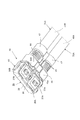
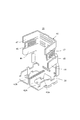
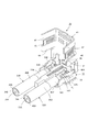
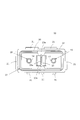
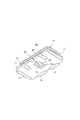
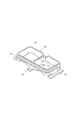
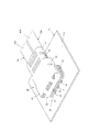
- FIG. 3 is a perspective view looking down from above showing an example of the coaxial connector device according to the present invention together with the first and second coaxial cables connected thereto. It is the perspective view looked up from the bottom which shows an example of the coaxial connector device concerning the invention in this application with the 1st and 2nd coaxial cable connected to it. It is a perspective view showing a grounding contact member with which an example of a coaxial connector device concerning the present invention is provided. It is a perspective view which shows the process in which the 1st and 2nd coaxial cable is connected to an example of the coaxial connector apparatus which concerns on this invention.
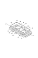
- FIG. 6 is a perspective view showing a grounding connection contact member included in an example of a mating coaxial connector device into which an example of the coaxial connector device according to the present invention is fitted and connected.
- FIG. 3 is a perspective view showing a state in which an example of the coaxial connector device according to the present invention, to which a plurality of coaxial cables are connected, is arranged so as to face an example of a counterpart coaxial connector device mounted on a circuit board.
- FIG. 9 is a perspective view showing a state in which an example of the coaxial connector device according to the present invention, to which a plurality of coaxial cables are connected, is fitted and connected to an example of a counterpart coaxial connector device mounted on a circuit board. It is a top view showing the state where an example of the coaxial connector device concerning the present invention to which the 1st and 2nd coaxial cable was connected was fitted and connected to an example of the other party coaxial connector device.
- FIG. 6 is a side view showing a state in which an example of the coaxial connector device according to the present invention to which the first and second coaxial cables are connected is fitted and connected to an example of the counterpart coaxial connector device.
- FIG. 12 is a sectional view showing a section taken along line XIII-XIII in FIG. 11.
- FIG. 12 is a sectional view showing a section taken along the line XIV-XIV in FIG. 11.
- FIG. 13 is a sectional view showing a section taken along line XV-XV in FIG. 12. It is a graph which shows the experimental result about a signal transmission state under the condition that an example of the coaxial connector device concerning the invention in this application was fitted and connected to the other party coaxial connector device.
- FIG. 1 and 2 show a coaxial connector device 30 which is an example of the coaxial connector device according to the present invention, together with a part of each of the first and second coaxial cables 31A and 31B connected thereto.
- the coaxial connector device 30 shown in FIGS. 1 and 2 is a counterpart that forms a board-side coaxial connector device attached to a component mounting surface of a circuit board under the condition that the first and second coaxial cables 31A and 31B are connected. It is used as a cable side coaxial connector device that is fitted and connected to the coaxial connector device.
- the coaxial connector device 30 includes a first signal contact member 33A, a second signal contact member 33B, a grounding contact member 35, and an insulating housing 36 as main components.
- the first signal contact member 33A is made of a conductive material and electrically connected to the central conductor 32A of the first coaxial cable 31A.
- the second signal contact member 33B is made of a conductive material and electrically connected to the center conductor 32B of the second coaxial cable 31B.
- the ground contact member 35 is made of a conductive material, and is electrically connected to the outer conductor 34A of the first coaxial cable 31A and the outer conductor 34B of the second coaxial cable 31B, so that the ground potential is reduced. Given.
- the insulating housing 36 is made of an insulating material such as a synthetic resin material, and supports the first signal contact member 33A, the second signal contact member 33B, and the ground contact member 35 in a mutually insulated state.
- the central conductor 32A is electrically connected to the first signal contact member 33A
- the outer conductor 34A is electrically connected to the ground contact member 35.
- the second coaxial cable 31B has its center conductor 32B electrically connected to the second signal contact member 33B and its outer conductor.
- 34B is electrically connected to the grounding contact member 35 and connected to the coaxial connector device 30.
- the insulating housing 36 has a first base portion 38A having a rectangular through hole 37A formed in the central portion and a second base portion 38B having a rectangular through hole 37B formed in the central portion, which are adjacent to each other.
- the first base portion 38A holds the first signal contact member 33A
- the second base portion 38B holds the second signal contact member 33B.
- the first signal contact member 33A and the second signal contact member 33B are arranged so as to be close to each other at a relatively small interval, that is, at a small interval.
- the ground contact member 35 has an annular fitting portion 39 that substantially surrounds the first base portion 38A and the second base portion 38B of the insulating housing 36, and the annular fitting portion 39 has the first fitting portion 39A. It is arranged around the first signal contact member 33A held by the base portion 38A and the second signal contact member 33B held by the second base portion 38B. Then, the first base portion 38A and the second base portion 38B of the insulating housing 36 and the annular fitting portion 39 of the grounding contact member 35 constitute a fitting connecting portion in the coaxial connector device 30.
- the coaxial connector device 30 to which the coaxial cable 31A and the second coaxial cable 31B are connected is fitted and connected to the mating coaxial connector device that constitutes the board-side coaxial connector device with such a fitting connection portion.
- the insulating housing 36 includes, in addition to the first base portion 38A and the second base portion 38B, a bending contact portion extending from one end of the first base portion 38A so as to be bendable. 40A and a folding contact portion 40B extending from one end of the second base portion 38B in a bendable manner are provided.
- Each of the bending contact portion 40A and the bending contact portion 40B forms a flat plate-like portion as a whole, and when bent, the bent signal contact member 33A and the second signal contact member 33B are provided to the first signal contact member 33A and the second signal contact member 33B. It is supposed to contact each other.
- the annular fitting portion 39 of the grounding contact member 35 has a flat plate extending from a part thereof to the inside of the annular body formed by the annular fitting portion 39.
- a partition wall member 41 is provided. That is, the flat partition wall member 41 is configured integrally with the ground contact member 35.
- the flat partition wall member 41 includes the first signal contact member 33A held by the first base portion 38A of the insulating housing 36 and the first contact member 33A of the insulating housing 36 when the grounding contact member 35 is supported by the insulating housing 36.
- the second signal contact member 33B held by the second base portion 38B is sandwiched between the second signal contact member 33B and the second signal contact member 33B.
- the plate-shaped partition wall member 41 is arranged within the small space between the first signal contact member 33A and the second signal contact member 33B, and is arranged between the first signal contact member 33A and the second signal contact member 33A.
- the signal contact member 33B is separated from the signal contact member 33B.
- the central conductor 32A is connected to the first signal contact member 33A
- the outer conductor 34A is connected to the grounding contact member 35
- the first coaxial cable 31A is connected to the coaxial connector device 30.
- the center conductor 32B is connected to the second signal contact member 33B
- the outer conductor 34B is connected to the ground contact member 35
- the second coaxial cable 31B is connected to the coaxial connector device 30.
- the first signal contact member 33A and the second signal contact member 33B are They are electromagnetically shielded from each other by the flat plate-shaped partition wall member 41 which is provided with the ground potential.
- an engagement connecting portion 41a which is in contact with a grounding connection contact member of the counterpart coaxial connector device when the coaxial connector device 30 is fitted and connected to the counterpart coaxial connector device. It is provided.
- the engaging connecting portion 41a of the flat partition wall member 41 comes into contact with the ground connection contact member of the mating coaxial connector device, so that the ground contact member 35 provided with the flat partition wall member 41 and the mating coaxial connector. The interconnection with the connecting contact member for grounding in the device is robust.
- the annular fitting portion 39 of the ground contact member 35 is provided with a pair of cable support portions 42A and 42B with the rising portion of the flat partition wall member 41 interposed therebetween.
- the cable support portion 42A supports the first coaxial cable 31A in which the center conductor 32A is connected to the first signal contact member 33A, and the cable support portion 42B has the center conductor 32B in the second signal contact. It supports the second coaxial cable 31B connected to the member 33B.
- the ground contact member 35 is provided with a shell portion 43 extending from one end of the annular fitting portion 39 so as to be bendable (bendable).
- the shell portion 43 is bent, as shown in FIG. 13 described later, the bending contact portions 40A and 40B of the insulating housing 36 are bent accordingly, and the central conductor 32A is used for the first signal.
- the outer conductor 34A and the center conductor 32B of the first coaxial cable 31A connected to the contact member 33A are connected to the outer conductor 34B of the second coaxial cable 31B connected to the second signal contact member 33B, respectively. To be done.
- the shell portion 43 is provided with a pair of first bending engagement portions 44, a pair of second bending engagement portions 45, and a pair of third bending engagement portions 47.
- the pair of first bending engagement portions 44 are bent and engage with the cable support portions 42A and 42B, respectively.
- the pair of second bending engagement portions 45 are bent so that the outer conductor 34A and the central conductor 32B of the first coaxial cable 31A whose central conductor 32A is connected to the first signal contact member 33A are second. To the outer conductor 34B of the second coaxial cable 31B connected to the signal contact member 33B.
- the pair of third bending engagement portions 47 are bent so that the skin insulator 46A and the center conductor 32B of the first coaxial cable 31A in which the center conductor 32A is connected to the first signal contact member 33A are the first conductor 32A.
- the second coaxial cable 31B connected to the second signal contact member 33B is engaged with the skin insulator 46B.
- the coaxial connector device 30 including the insulating housing 36, the first signal contact member 33A and the second signal contact member 33B, and the grounding contact member 35 has the first connector
- the shell portion 43 provided on the grounding contact member 35 was left unfolded.
- the first coaxial cable 31A has the outer conductor 34A and the center conductor 32A exposed at one end thereof, and the exposed outer conductor 34A is a cable supporting portion of the ground contact member 35. 42A, and the exposed central conductor 32A abuts on the first signal contact member 33A.
- outer conductor 34B and the center conductor 32B are exposed at one end of the second coaxial cable 31B, and the exposed outer conductor 34B is the cable supporting portion of the ground contact member 35.
- the exposed central conductor 32B is placed in contact with the second signal contact member 33B while being in contact with the second signal contact member 33B.
- the shell portion 43 provided on the ground contact member 35 is bent toward the annular fitting portion 39.
- the bent contact portion 40A provided in the insulating housing 36 is bent by the shell portion 43 and pressed against the first signal contact member 33A so that the central conductor 32A of the first coaxial cable 31A moves to the first conductor 32A.
- the bent contact portion 40B provided on the insulating housing 36 is bent by the shell portion 43 and pressed against the second signal contact member 33B.
- the center conductor 32B of the second coaxial cable 31B is brought into contact with the second signal contact member 33B to be firmly connected thereto.
- the bent shell portion 43 abuts on the outer conductor 34A of the first coaxial cable 31A abutting on the cable support portion 42A provided on the annular fitting portion 39, and has the outer conductor 34A.
- the coaxial cable 31A is sandwiched between the cable support portion 42A and the outer conductor 34B of the second coaxial cable 31B that is in contact with the cable support portion 42B provided in the annular fitting portion 39.
- the second coaxial cable 31B having the above is held between the cable supporting portion 42B and the second coaxial cable 31B.
- the first bent engagement portions 44 provided in the shell portion 43 are bent so as to be close to each other, and the cable support portions that respectively support the first coaxial cable 31A and the second coaxial cable 31B. 42A and 42B are engaged with each other, and the pair of second bending engagement portions 45 provided on the shell portion 43 are bent so as to be close to each other, so that the central conductor 32A has the first portion.
- the outer conductor 34A and the center conductor 32B of the first coaxial cable 31A connected to the signal contact member 33A are respectively engaged with the outer conductor 34B of the second coaxial cable 31B connected to the second signal contact member 33B.
- the pair of third bending engagement portions 47 provided in the shell portion 43 are bent so as to be close to each other, and the central conductor 32A is made to be the first signal coil.
- the skin insulator 46A and the center conductor 32B of the first coaxial cable 31A connected to the tact member 33A are respectively engaged with the skin insulator 46B of the second coaxial cable 31B connected to the second signal contact member 33B.
- the first coaxial cable 31A and the second coaxial cable 31B are firmly connected to the coaxial connector device 30, and as a result, the coaxial connector device 30 is placed in the state shown in FIGS. 1 and 2 described above. It will be.
- the board-side coaxial connector device 10 shown in FIGS. 5, 6 and 7 is a coaxial connector device 30 which is an example of the coaxial connector device according to the present invention to which the first and second coaxial cables 31A and 31B are connected. It is supposed to be fitted and connected.
- the board-side coaxial connector device 10 is mounted on the component mounting surface 11a of the circuit board 11 shown in FIGS. 9 and 10 which will be described later, although the illustration is omitted in FIGS. 5, 6 and 7. It is fixed and put to practical use.
- the board-side coaxial connector device 10 includes an insulating base 13, a first signal connection contact member 16, and a second signal connection contact member 19.
- the insulating base 13 is formed in a flat plate shape with an insulating material such as a synthetic resin material, and is arranged on the component mounting surface 11 a of the circuit board 11.
- the first signal connecting contact member 16 is made of a metal material, is assembled to the insulating base 13, projects from the insulating base 13, and is electrically connected to the central conductor 32A of the first coaxial cable 31A of the coaxial connector device 30.
- the convex contact portion 14 in which the first signal contact member 33A that has been connected is in contact and engaged, and the component of the circuit board 11 extending from the convex contact portion 14 to the outside of the insulating substrate 13.
- a signal connection portion 15 connected to the signal terminal arranged on the equal mounting surface 11a is provided.
- the second signal connecting contact member 19 is also made of a metal material and is assembled to the insulating base 13, and protrudes from the insulating base 13 to electrically connect with the center conductor 32B of the second coaxial cable 31B of the coaxial connector device 30.
- the convex contact portion 17 that is to be engaged with the second signal contact member 33 ⁇ / b> B.
- a signal connecting portion 18 connected to the signal terminal portion arranged on the component mounting surface 11a is provided.
- the convex contact portion 14 of the first signal connecting contact member 16 and the convex contact portion 17 of the second signal connecting contact member 19 have a relatively small space on the insulating base 13, that is, a small space. Are arranged so as to face each other.
- the board-side coaxial connector device 10 also includes an annular contact portion 20, a ground connection contact member 22, and a conductive partition wall member 23.
- the annular contact portion 20 is made of a metal material and is assembled to the insulating base 13, and has a convex contact portion 14 in the first signal connecting contact member 16 and a convex contact portion 17 in the second signal connecting contact member 19.
- the ring-shaped fitting of the grounding contact member 35 which is arranged so as to surround and are connected to the outer conductor 34A of the first coaxial cable 31A and the outer conductor 34B of the second coaxial cable 31B in the coaxial connector device 30, respectively.
- the portion 39 is in contact and engagement.
- the grounding connection contact member 22 is provided with a grounding connection portion 21 that extends from the annular contact portion 20 to the outside of the insulating base 13 and is connected to a ground terminal portion arranged on the component mounting surface 11 a of the circuit board 11. It is considered to have been
- the conductive partition wall member 23 is supported by the pair of projecting support portions 13 a provided on the insulating base 13, and the convex contact portion 14 and the second signal connecting contact member of the first signal connecting contact member 16 are supported. It is arranged so as to be sandwiched between the convex contact portion 17 of 19 and the ground potential.
- the conductive partition wall member 23 has the convex contact portion 14 of the first signal connection contact member 16 of the insulating base 13 and the convex contact portion 17 of the second signal connection contact member 19. Between the convex contact portion 14 of the first signal connecting contact member 16 and the convex contact portion 17 of the second signal connecting contact member 19. However, they are electromagnetically shielded from each other by the conductive partition wall member 23 which is provided with the ground potential.
- the board-side coaxial connector device 10 includes the insulating base 13, the first signal connecting contact member 16 having the convex contact portion 14, and the second signal connecting contact having the convex contact portion 17.
- the sex partition wall member 23 is provided.
- a part of the annular contact portion 20 of the ground connection contact member 22 and the conductive partition wall member 23 surround the convex contact portion 14 of the first signal connection contact member 16.
- the other part of the annular contact portion 20 of the ground connection contact member 22 and the conductive partition wall member 23 that form the conductive partition wall of No. 1 and the convex contact portion 17 of the second signal connection contact member 19.
- FIG. 8 shows a specific configuration example of the grounding contact member 22.
- the whole is formed by punching, pressing and bending a metal plate material.
- the annular contact portion 20 that surrounds the convex contact portion 14 of the first signal connecting contact member 16 and the convex contact portion 17 of the second signal connecting contact member 19 is a rectangular annular body.
- the plurality of ground connection portions 21 are bent and extend from the annular contact portion 20.
- the plurality of ground connection portions 21 are connected to ground terminal portions arranged on the component mounting surface 11 a of the circuit board 11.
- the conductive partition wall member 23 extends from a part of the annular contact portion 20 to the inside of the rectangular annular body formed by the annular contact portion 20 by bending so as to divide the rectangular annular body in two.
- the conductive partition wall member 23, which constitutes a part of the annular contact portion 20, is configured integrally with the grounding connection contact member 22.
- the conductive partition wall member 23 is in a state in which one end portion of the conductive partition wall member 23 is engaged with the engagement connecting portion 41 a of the flat plate-shaped partition wall member 41 of the coaxial connector device 30.
- a mating connection portion 23a is provided.
- the conductive partition wall member 23 has a through hole 24 provided in the insulating base 13 at the other end portion opposite to the one end portion provided with the engaging connection portion 23a.
- a board connecting portion 23b extending through the insulating substrate 13 is provided, and the board connecting portion 23b is connected to a ground terminal portion arranged on the component mounting surface 11a of the circuit board 11.
- the conductive partition wall member 23 is integrally formed with the grounding connection contact member 22, but the conductive partition wall member 23 is not always used for grounding.
- the conductive partition wall member 23 does not need to be configured integrally with the connection contact member 22, and may be configured separately from the grounding connection contact member 22.
- the board connecting portion 23b extending from the conductive partition wall member 23 through the insulating base 13 through the through hole 24 provided in the insulating base 13 is provided, and the board connecting portion 23b is connected to the circuit board 11.
- the partition wall member 23 is firmly installed on the circuit board 11. As seen in the board-side coaxial connector device 10 described above, when the conductive partition wall member 23 is configured integrally with the ground connection contact member 22, the number of components is reduced. It is possible to obtain the advantage that the structure can be simplified and the conductive partition wall member 23 can be firmly arranged in the insulating base 13.
- the board-side coaxial connector device 10 is mounted on the mounting surface of the circuit board 11 such as components. 11a, that is, the insulating substrate 13 is disposed on the surface of the circuit board 11 and is fixed to the circuit board 11, and the first coaxial connector device 10 is fixed to the circuit board 11.
- the coaxial connector device 30 to which the coaxial cable 31A and the second coaxial cable 31B are connected is arranged to face each other.
- the first signal contact member 33A and the second signal contact member 33B in the coaxial connector device 30 are connected to the convex contact portion 14 in the first signal connection contact member 16 in the board-side coaxial connector device 10 and
- the annular fitting portion 39 of the ground contact member 35 of the coaxial connector device 30 is located at a position corresponding to each of the convex contact portions 17 of the second signal connection contact member 19 and the ground of the board-side coaxial connector device 10.
- the connection contact member 22 has a position corresponding to the annular contact portion 20.
- the coaxial connector device 30 to which the first coaxial cable 31A and the second coaxial cable 31B are connected is displaced toward the board-side coaxial connector device 10 fixed to the circuit board 11, and FIG. As shown in FIG. 3, the board-side coaxial connector device 10 is fitted and connected.
- the first signal contact member 33A to which the central conductor 32A of the first coaxial cable 31A in the coaxial connector device 30 is electrically connected and the central conductor 32B of the second coaxial cable 31B are electrically connected.
- the connected second signal contact member 33B has the convex contact portion 14 in the first signal connection contact member 16 and the convex contact portion in the second signal connection contact member 19 of the board-side coaxial connector device 10.
- grounding contact members 35 which are respectively brought into contact with each other and connected to the outer conductor 34A of the first coaxial cable 31A and the outer conductor 34B of the second coaxial cable 31B in the coaxial connector device 30.
- a ring-shaped fitting portion 39 provided on the grounding connection contact member 22 of the board-side coaxial connector device 10. It is fitting contact connected to the contact portion 20. That is, the ground contact member 35 is brought into contact engagement with the annular contact portion 20.
- the first coaxial cable 31A and the second coaxial cable 31B are connected to the circuit board 11 via the coaxial connector device 30 and the board-side coaxial connector device 10, respectively.
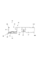
- FIG. 11 plan view
- FIG. 12 side view
- the coaxial connector device 30 in which the first coaxial cable 31A and the second coaxial cable 31B are connected is fitted and connected to the board-side coaxial connector device 10.
- the state is shown by omitting the illustration of the circuit board 11.
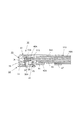
- FIG. 13 which is a cross-sectional view showing a cross section taken along line XIII-XIII in FIG. 11, in the coaxial connector device 30, With the central conductor 32A of the first coaxial cable 31A being sandwiched by the first signal contact member 33A pressed by the bent contact portion 40A provided in the insulating housing 36, the first signal contact is held.
- the second coaxial cable 31B has a center conductor 32B provided in the insulating housing 36 in the same manner as the first coaxial cable 31A. It is electrically connected to the second signal contact member 33B in a state of being sandwiched by the second signal contact member 33B pressed by the contact portion 40B, and the outer conductor 34B thereof is connected to the ground contact. It is connected to the cable support portion 42B and the shell portion 43 provided on the annular fitting portion 39 of the member 35.
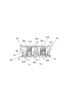
- FIG. 15 which is a cross-sectional view showing a cross section taken along line XV-XV in FIG. 12
- a pair of first signal contact members 33A of the coaxial connector device 30 are provided.
- the mutually opposing contact connecting portion 50A is in contact with and engaged with the convex contact portion 14 in a state of sandwiching the convex contact portion 14 of the first signal connecting contact member 16 of the board-side coaxial connector device 10, and
- the pair of mutually opposing contact connection parts 50B provided on the second signal contact member 33B of the coaxial connector device 30 are the convex contact parts 17 of the second signal connection contact member 19 of the board-side coaxial connector device 10.
- the ring-shaped fitting portion 39 in the grounding contact member 35 of the coaxial connector device 30 is in contact with the convex contact portion 17 and
- the ring-shaped contact portion 22 of the grounding connection contact member 22 of the side coaxial connector device 10 is in contact with and engaged with the annular contact portion 20.
- FIG. 14 which is a cross-sectional view showing a cross section taken along the line XIV-XIV in FIG. 11
- a flat plate partition wall member 41 provided in the annular fitting portion 39 of the ground contact member 35 of the coaxial connector device 30 is provided.
- the engagement connection portion 41a provided therein is brought into contact engagement with the engagement connection portion 23a provided on the conductive partition wall member 23 in the board-side coaxial connector device 10.
- the flat partition wall member 41 in the coaxial connector device 30 and the conductive partition wall member 23 in the board-side coaxial connector device 10 are engaged with each other under the ground potential.
- the coaxial connector device 30 to which the first coaxial cable 31A and the second coaxial cable 31B are connected is fitted to the substrate-side coaxial connector device 10 fixed to the circuit substrate 11, as shown in FIG.
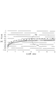
- the test signal St is input to the signal connection portion 15 provided on the first signal connection contact member 16 of the board-side coaxial connector device 10 under the interlocked condition, the first board-side coaxial connector device 10
- required the electric power ratio with respect to the input test high frequency signal St about the test signal St output to the signal connection part 18 provided in the signal connection contact member 19 of 2 is shown. In the graph shown in FIG.
- the horizontal axis represents the frequency (GHz) of the test signal St
- the vertical axis represents the power ratio (dB)
- the broken line curve PR1 indicates that the coaxial connector device 30 includes the flat partition wall member 41.
- the solid line curve PR2 is the power ratio obtained under the condition that the coaxial connector device 30 is provided with the flat partition wall member 41.
- the power ratio represented by the solid line curve PR2 that is, the coaxial connector device 30 is the flat plate-shaped partition wall member over the entire frequency range up to the frequency 6 GHz for the test signal St.
- the power ratio obtained with 41 is obtained with the power ratio represented by the broken line curve PR1, that is, the coaxial connector device 30 is not provided with the flat partition wall member 41. It is below the power ratio.
- the first signal contact member 33A and the first signal contact member 33A arranged inside the annular fitting portion 39 of the ground contact member 35 are provided.
- the circuit board to which the board-side coaxial connector device 10 to which the coaxial connector device 30 is fitted and connected is mounted by disposing the second signal contact member 33B in close proximity to each other with a small gap. It is possible to reduce the occupied area of the coaxial connector device 30 on the component mounting surface 11a of 11 and the like.
- the flat plate-shaped partition wall member 41 to which the ground potential is applied is arranged within the small interval between the first signal contact member 33A and the second signal contact member 33B,
- the first signal contact member 33A and the second signal contact member 33B are electromagnetically shielded from each other by the flat partition wall member 41 to which the ground potential is applied, whereby the first signal contact member 33A and the second signal contact member 33B are shielded from each other.
- the high frequency signal transmitted through the signal contact member 33A is mixed into the high frequency signal transmitted through the second signal contact member 33B as crosstalk noise and transmitted through the second signal contact member 33B.
- Mixing of high-frequency signals into the high-frequency signals transmitted through the first signal contact member 33A as crosstalk noise is light. It is, with the result that it is possible to suppress a situation where deterioration in the transmission characteristics of the high-frequency signal transmitted through each of the first signal contact members 33A and second signal contact member 33B is provided.
- the flat partition wall member 41 is integrally formed with the ground contact member 35 as a part extending from a part of the annular fitting portion 39 of the ground contact member 35. Therefore, the number of constituent parts can be reduced, the structure can be simplified, and the flat partition wall member 41 in the insulating housing 36 can be firmly arranged.
- the coaxial connector device according to the present invention as described above is fitted and connected to the counterpart coaxial connector device, which is a board-side coaxial connector device mounted on the component surface of the circuit board after the two coaxial cables are connected.
- the counterpart coaxial connector device which is a board-side coaxial connector device mounted on the component surface of the circuit board after the two coaxial cables are connected.
- outer conductor 35 ... ground contact member, 36 ... insulating housing, 37 , 37B ... rectangular through hole, 38A ... first base part, 38B ... second base part, 39 ... annular fitting part, 40A, 40B ... folded contact part, 41 ... flat plate partition wall member, 41a ... engagement Connection part, 42A, 42B ... Cable support part, 43 ... Shell part, 44 ... First bent engagement part, 45 ... Second bent engagement part, 46A, 46B ... Skin insulator, 47 ... Third Bent engagement part.
Landscapes
- Coupling Device And Connection With Printed Circuit (AREA)
- Details Of Connecting Devices For Male And Female Coupling (AREA)
- Multi-Conductor Connections (AREA)
Abstract
L'invention concerne un dispositif de connecteur coaxial 30 qui est configuré avec : un premier élément de contact de signal 33A qui est connecté au conducteur central 32A d'un premier câble coaxial 31A ; un second élément de contact de signal 33B qui est connecté au conducteur central 32B d'un second câble coaxial 31B ; un élément de contact de masse 35 qui a une unité d'ajustement annulaire 39 disposée autour des premier et second éléments de contact de signal 33A, 33B et qui est connectée à des conducteurs extérieurs 34A, 34B des premier et second câbles coaxiaux 31A, 31B ; et un élément de paroi de séparation plat 41 qui est disposé entre le premier élément de contact de signal 33A et le second élément de contact de signal 33B et auquel le potentiel de masse est appliqué.
Priority Applications (2)
| Application Number | Priority Date | Filing Date | Title |
|---|---|---|---|
| CN201980070114.4A CN112913089B (zh) | 2018-10-26 | 2019-10-23 | 同轴连接器装置 |
| US17/237,059 US11721940B2 (en) | 2018-10-26 | 2021-04-22 | Coaxial connector with partition |
Applications Claiming Priority (2)
| Application Number | Priority Date | Filing Date | Title |
|---|---|---|---|
| JP2018201508A JP7187975B2 (ja) | 2018-10-26 | 2018-10-26 | 同軸コネクタ装置 |
| JP2018-201508 | 2018-10-26 |
Related Child Applications (1)
| Application Number | Title | Priority Date | Filing Date |
|---|---|---|---|
| US17/237,059 Continuation US11721940B2 (en) | 2018-10-26 | 2021-04-22 | Coaxial connector with partition |
Publications (1)
| Publication Number | Publication Date |
|---|---|
| WO2020085401A1 true WO2020085401A1 (fr) | 2020-04-30 |
Family
ID=70331098
Family Applications (1)
| Application Number | Title | Priority Date | Filing Date |
|---|---|---|---|
| PCT/JP2019/041572 Ceased WO2020085401A1 (fr) | 2018-10-26 | 2019-10-23 | Dispositif de connecteur coaxial |
Country Status (4)
| Country | Link |
|---|---|
| US (1) | US11721940B2 (fr) |
| JP (1) | JP7187975B2 (fr) |
| CN (1) | CN112913089B (fr) |
| WO (1) | WO2020085401A1 (fr) |
Families Citing this family (10)
| Publication number | Priority date | Publication date | Assignee | Title |
|---|---|---|---|---|
| WO2020085398A1 (fr) | 2018-10-26 | 2020-04-30 | 第一精工株式会社 | Dispositif de connecteur coaxial |
| JP7187975B2 (ja) * | 2018-10-26 | 2022-12-13 | I-Pex株式会社 | 同軸コネクタ装置 |
| JP6780689B2 (ja) * | 2018-11-21 | 2020-11-04 | I−Pex株式会社 | 電気コネクタ及びコネクタ装置 |
| WO2021225122A1 (fr) * | 2020-05-07 | 2021-11-11 | I-Pex株式会社 | Connecteur électrique |
| JP7235175B2 (ja) * | 2020-07-31 | 2023-03-08 | 株式会社村田製作所 | プラグ及びコネクタセット |
| US20240128687A1 (en) * | 2021-03-11 | 2024-04-18 | Ls Mtron Ltd. | Connector |
| US20240235080A9 (en) * | 2021-03-11 | 2024-07-11 | Ls Mtron Ltd. | Connector |
| US12609494B2 (en) | 2021-03-26 | 2026-04-21 | Ls Mtron Ltd. | Connector |
| JP2024170681A (ja) * | 2021-10-06 | 2024-12-11 | 宏致電子股▲ふん▼有限公司 | コネクター、コネクターセット及びコネクター付きケーブル |
| CN115224544A (zh) * | 2022-05-30 | 2022-10-21 | 信维通信(江苏)有限公司 | 公端连接器及射频连接器组件 |
Citations (4)
| Publication number | Priority date | Publication date | Assignee | Title |
|---|---|---|---|---|
| JP2003297502A (ja) * | 2002-04-05 | 2003-10-17 | Emuden Musen Kogyo Kk | 同軸コネクタ |
| JP2010278007A (ja) * | 2009-05-29 | 2010-12-09 | Tyco Electronics Nederland Bv | 小型スイッチコネクタ |
| JP2012099299A (ja) * | 2010-11-01 | 2012-05-24 | Japan Aviation Electronics Industry Ltd | 同軸コネクタ |
| JP2016100190A (ja) * | 2014-11-21 | 2016-05-30 | 第一精工株式会社 | 同軸コネクタ組立て |
Family Cites Families (7)
| Publication number | Priority date | Publication date | Assignee | Title |
|---|---|---|---|---|
| US5102353A (en) | 1991-06-06 | 1992-04-07 | Molex Incorporated | Electrical connectors |
| JP3361645B2 (ja) | 1995-03-03 | 2003-01-07 | 富士通株式会社 | ジャックコネクタ及びジャックコネクタを含むコネクタ |
| JP5912189B2 (ja) | 2012-11-30 | 2016-04-27 | 宏致電子股▲ふん▼有限公司Aces Electronics Co.,Ltd. | コネクタ |
| JP6269558B2 (ja) * | 2014-06-05 | 2018-01-31 | 株式会社村田製作所 | コネクタセット及びコネクタ |
| JP6806028B2 (ja) | 2017-01-19 | 2020-12-23 | 株式会社村田製作所 | 多極コネクタセット |
| WO2020085398A1 (fr) * | 2018-10-26 | 2020-04-30 | 第一精工株式会社 | Dispositif de connecteur coaxial |
| JP7187975B2 (ja) * | 2018-10-26 | 2022-12-13 | I-Pex株式会社 | 同軸コネクタ装置 |
-
2018
- 2018-10-26 JP JP2018201508A patent/JP7187975B2/ja active Active
-
2019
- 2019-10-23 WO PCT/JP2019/041572 patent/WO2020085401A1/fr not_active Ceased
- 2019-10-23 CN CN201980070114.4A patent/CN112913089B/zh active Active
-
2021
- 2021-04-22 US US17/237,059 patent/US11721940B2/en active Active
Patent Citations (4)
| Publication number | Priority date | Publication date | Assignee | Title |
|---|---|---|---|---|
| JP2003297502A (ja) * | 2002-04-05 | 2003-10-17 | Emuden Musen Kogyo Kk | 同軸コネクタ |
| JP2010278007A (ja) * | 2009-05-29 | 2010-12-09 | Tyco Electronics Nederland Bv | 小型スイッチコネクタ |
| JP2012099299A (ja) * | 2010-11-01 | 2012-05-24 | Japan Aviation Electronics Industry Ltd | 同軸コネクタ |
| JP2016100190A (ja) * | 2014-11-21 | 2016-05-30 | 第一精工株式会社 | 同軸コネクタ組立て |
Also Published As
| Publication number | Publication date |
|---|---|
| JP2020068163A (ja) | 2020-04-30 |
| JP7187975B2 (ja) | 2022-12-13 |
| US11721940B2 (en) | 2023-08-08 |
| US20210242631A1 (en) | 2021-08-05 |
| CN112913089B (zh) | 2023-04-07 |
| CN112913089A (zh) | 2021-06-04 |
Similar Documents
| Publication | Publication Date | Title |
|---|---|---|
| WO2020085401A1 (fr) | Dispositif de connecteur coaxial | |
| CN112913090B (zh) | 同轴连接器装置 | |
| KR101157775B1 (ko) | 동축 커넥터 장치 | |
| JP5757153B2 (ja) | 同軸コネクタ装置 | |
| CN105100561A (zh) | 摄像装置 | |
| TW201330420A (zh) | 同軸連接器裝置 | |
| JP2016100190A (ja) | 同軸コネクタ組立て | |
| CN104348038B (zh) | 同轴型电连接器 | |
| TW201820728A (zh) | 同軸纜線連接器及同軸纜線連接方法 | |
| CN105826709B (zh) | 同轴型电连接器 | |
| KR102311608B1 (ko) | 초고주파 신호 전송용 소형 커넥터 | |
| JP2015130266A (ja) | 同軸コネクタ装置 | |
| JP6915392B2 (ja) | 同軸コネクタ装置 | |
| WO2024057664A1 (fr) | Connecteur, ensemble connecteur, dispositif de connexion et connecteur homologue | |
| JP7363228B2 (ja) | コネクタ装置、コネクタ、及びコネクタ構造 | |
| JP7596783B2 (ja) | 電気コネクタ | |
| JP7247814B2 (ja) | 電気コネクタ及び電気コネクタ対 | |
| JP2023033144A (ja) | コネクタ変換部品およびコネクタ | |
| JP2017139154A (ja) | 同軸コネクタ装置 | |
| KR101759286B1 (ko) | 트랜지션 도파관 및 트랜지션 부재 | |
| JP2015076311A (ja) | 同軸コネクタ装置 | |
| WO2022009619A1 (fr) | Connecteur électrique | |
| JP2017157291A (ja) | 同軸コネクタ装置 | |
| JP2017004631A (ja) | コネクタ装置 |
Legal Events
| Date | Code | Title | Description |
|---|---|---|---|
| 121 | Ep: the epo has been informed by wipo that ep was designated in this application |
Ref document number: 19875650 Country of ref document: EP Kind code of ref document: A1 |
|
| NENP | Non-entry into the national phase |
Ref country code: DE |
|
| 122 | Ep: pct application non-entry in european phase |
Ref document number: 19875650 Country of ref document: EP Kind code of ref document: A1 |