WO2020085460A1 - Procédé de fabrication de feuille façonnée - Google Patents
Procédé de fabrication de feuille façonnée Download PDFInfo
- Publication number
- WO2020085460A1 WO2020085460A1 PCT/JP2019/041790 JP2019041790W WO2020085460A1 WO 2020085460 A1 WO2020085460 A1 WO 2020085460A1 JP 2019041790 W JP2019041790 W JP 2019041790W WO 2020085460 A1 WO2020085460 A1 WO 2020085460A1
- Authority
- WO
- WIPO (PCT)
- Prior art keywords
- sheet
- roll
- sheets
- shaped
- concave portion
- Prior art date
- Legal status (The legal status is an assumption and is not a legal conclusion. Google has not performed a legal analysis and makes no representation as to the accuracy of the status listed.)
- Ceased
Links
Images




Classifications
-
- A—HUMAN NECESSITIES
- A61—MEDICAL OR VETERINARY SCIENCE; HYGIENE
- A61F—FILTERS IMPLANTABLE INTO BLOOD VESSELS; PROSTHESES; DEVICES PROVIDING PATENCY TO, OR PREVENTING COLLAPSING OF, TUBULAR STRUCTURES OF THE BODY, e.g. STENTS; ORTHOPAEDIC, NURSING OR CONTRACEPTIVE DEVICES; FOMENTATION; TREATMENT OR PROTECTION OF EYES OR EARS; BANDAGES, DRESSINGS OR ABSORBENT PADS; FIRST-AID KITS
- A61F13/00—Bandages or dressings; Absorbent pads
- A61F13/15—Absorbent pads, e.g. sanitary towels, swabs or tampons for external or internal application to the body; Supporting or fastening means therefor; Tampon applicators
- A61F13/15577—Apparatus or processes for manufacturing
- A61F13/15699—Forming webs by bringing together several webs, e.g. by laminating or folding several webs, with or without additional treatment of the webs
-
- B—PERFORMING OPERATIONS; TRANSPORTING
- B32—LAYERED PRODUCTS
- B32B—LAYERED PRODUCTS, i.e. PRODUCTS BUILT-UP OF STRATA OF FLAT OR NON-FLAT, e.g. CELLULAR OR HONEYCOMB, FORM
- B32B38/00—Ancillary operations in connection with laminating processes
- B32B38/06—Embossing
-
- A—HUMAN NECESSITIES
- A61—MEDICAL OR VETERINARY SCIENCE; HYGIENE
- A61F—FILTERS IMPLANTABLE INTO BLOOD VESSELS; PROSTHESES; DEVICES PROVIDING PATENCY TO, OR PREVENTING COLLAPSING OF, TUBULAR STRUCTURES OF THE BODY, e.g. STENTS; ORTHOPAEDIC, NURSING OR CONTRACEPTIVE DEVICES; FOMENTATION; TREATMENT OR PROTECTION OF EYES OR EARS; BANDAGES, DRESSINGS OR ABSORBENT PADS; FIRST-AID KITS
- A61F13/00—Bandages or dressings; Absorbent pads
- A61F13/15—Absorbent pads, e.g. sanitary towels, swabs or tampons for external or internal application to the body; Supporting or fastening means therefor; Tampon applicators
- A61F13/15577—Apparatus or processes for manufacturing
- A61F13/15707—Mechanical treatment, e.g. notching, twisting, compressing, shaping
-
- B—PERFORMING OPERATIONS; TRANSPORTING
- B32—LAYERED PRODUCTS
- B32B—LAYERED PRODUCTS, i.e. PRODUCTS BUILT-UP OF STRATA OF FLAT OR NON-FLAT, e.g. CELLULAR OR HONEYCOMB, FORM
- B32B37/00—Methods or apparatus for laminating, e.g. by curing or by ultrasonic bonding
- B32B37/10—Methods or apparatus for laminating, e.g. by curing or by ultrasonic bonding characterised by the pressing technique, e.g. using action of vacuum or fluid pressure
-
- B—PERFORMING OPERATIONS; TRANSPORTING
- B32—LAYERED PRODUCTS
- B32B—LAYERED PRODUCTS, i.e. PRODUCTS BUILT-UP OF STRATA OF FLAT OR NON-FLAT, e.g. CELLULAR OR HONEYCOMB, FORM
- B32B5/00—Layered products characterised by the non- homogeneity or physical structure, i.e. comprising a fibrous, filamentary, particulate or foam layer; Layered products characterised by having a layer differing constitutionally or physically in different parts
- B32B5/02—Layered products characterised by the non- homogeneity or physical structure, i.e. comprising a fibrous, filamentary, particulate or foam layer; Layered products characterised by having a layer differing constitutionally or physically in different parts characterised by structural features of a fibrous or filamentary layer
- B32B5/022—Non-woven fabric
-
- B—PERFORMING OPERATIONS; TRANSPORTING
- B32—LAYERED PRODUCTS
- B32B—LAYERED PRODUCTS, i.e. PRODUCTS BUILT-UP OF STRATA OF FLAT OR NON-FLAT, e.g. CELLULAR OR HONEYCOMB, FORM
- B32B5/00—Layered products characterised by the non- homogeneity or physical structure, i.e. comprising a fibrous, filamentary, particulate or foam layer; Layered products characterised by having a layer differing constitutionally or physically in different parts
- B32B5/22—Layered products characterised by the non- homogeneity or physical structure, i.e. comprising a fibrous, filamentary, particulate or foam layer; Layered products characterised by having a layer differing constitutionally or physically in different parts characterised by the presence of two or more layers which are next to each other and are fibrous, filamentary, formed of particles or foamed
- B32B5/24—Layered products characterised by the non- homogeneity or physical structure, i.e. comprising a fibrous, filamentary, particulate or foam layer; Layered products characterised by having a layer differing constitutionally or physically in different parts characterised by the presence of two or more layers which are next to each other and are fibrous, filamentary, formed of particles or foamed one layer being a fibrous or filamentary layer
- B32B5/26—Layered products characterised by the non- homogeneity or physical structure, i.e. comprising a fibrous, filamentary, particulate or foam layer; Layered products characterised by having a layer differing constitutionally or physically in different parts characterised by the presence of two or more layers which are next to each other and are fibrous, filamentary, formed of particles or foamed one layer being a fibrous or filamentary layer another layer next to it also being fibrous or filamentary
- B32B5/265—Layered products characterised by the non- homogeneity or physical structure, i.e. comprising a fibrous, filamentary, particulate or foam layer; Layered products characterised by having a layer differing constitutionally or physically in different parts characterised by the presence of two or more layers which are next to each other and are fibrous, filamentary, formed of particles or foamed one layer being a fibrous or filamentary layer another layer next to it also being fibrous or filamentary characterised by one fibrous or filamentary layer being a non-woven fabric layer
- B32B5/266—Layered products characterised by the non- homogeneity or physical structure, i.e. comprising a fibrous, filamentary, particulate or foam layer; Layered products characterised by having a layer differing constitutionally or physically in different parts characterised by the presence of two or more layers which are next to each other and are fibrous, filamentary, formed of particles or foamed one layer being a fibrous or filamentary layer another layer next to it also being fibrous or filamentary characterised by one fibrous or filamentary layer being a non-woven fabric layer next to one or more non-woven fabric layers
-
- A—HUMAN NECESSITIES
- A61—MEDICAL OR VETERINARY SCIENCE; HYGIENE
- A61F—FILTERS IMPLANTABLE INTO BLOOD VESSELS; PROSTHESES; DEVICES PROVIDING PATENCY TO, OR PREVENTING COLLAPSING OF, TUBULAR STRUCTURES OF THE BODY, e.g. STENTS; ORTHOPAEDIC, NURSING OR CONTRACEPTIVE DEVICES; FOMENTATION; TREATMENT OR PROTECTION OF EYES OR EARS; BANDAGES, DRESSINGS OR ABSORBENT PADS; FIRST-AID KITS
- A61F13/00—Bandages or dressings; Absorbent pads
- A61F13/15—Absorbent pads, e.g. sanitary towels, swabs or tampons for external or internal application to the body; Supporting or fastening means therefor; Tampon applicators
- A61F13/15577—Apparatus or processes for manufacturing
- A61F13/15707—Mechanical treatment, e.g. notching, twisting, compressing, shaping
- A61F13/15731—Treating webs, e.g. for giving them a fibrelike appearance, e.g. by embossing
-
- B—PERFORMING OPERATIONS; TRANSPORTING
- B32—LAYERED PRODUCTS
- B32B—LAYERED PRODUCTS, i.e. PRODUCTS BUILT-UP OF STRATA OF FLAT OR NON-FLAT, e.g. CELLULAR OR HONEYCOMB, FORM
- B32B2555/00—Personal care
- B32B2555/02—Diapers or napkins
-
- Y—GENERAL TAGGING OF NEW TECHNOLOGICAL DEVELOPMENTS; GENERAL TAGGING OF CROSS-SECTIONAL TECHNOLOGIES SPANNING OVER SEVERAL SECTIONS OF THE IPC; TECHNICAL SUBJECTS COVERED BY FORMER USPC CROSS-REFERENCE ART COLLECTIONS [XRACs] AND DIGESTS
- Y10—TECHNICAL SUBJECTS COVERED BY FORMER USPC
- Y10T—TECHNICAL SUBJECTS COVERED BY FORMER US CLASSIFICATION
- Y10T156/00—Adhesive bonding and miscellaneous chemical manufacture
- Y10T156/10—Methods of surface bonding and/or assembly therefor
- Y10T156/1002—Methods of surface bonding and/or assembly therefor with permanent bending or reshaping or surface deformation of self sustaining lamina
- Y10T156/1007—Running or continuous length work
- Y10T156/1023—Surface deformation only [e.g., embossing]
Definitions
- the present invention relates to a method for manufacturing a shaped sheet, and more particularly to a technique for manufacturing a shaped sheet in which a raised portion is formed on at least one of two sheets joined together.
- a shaped sheet in which a raised portion is formed on at least one of two sheets joined to each other is used for disposable wearable articles such as disposable diapers so that the raised portion contacts the skin, for example.
- Such a shaped sheet is manufactured as follows.
- FIG. 10 is an explanatory diagram of a method for manufacturing the shaped sheet 101.
- the first sheet 102 fed from the original roll 102 ′ is sandwiched between a pair of shaping rolls 111 and 112 having concave and convex portions formed on the outer peripheral surface so as to mesh with each other.
- the second sheet 103 fed from the original roll 103 ′ is overlapped with the first sheet 102 that is engaged with the irregularities on the outer peripheral surface of the one shaping roll 111, and both sheets 102 and 103 are The sheets 102 and 103 are bonded to each other by being sandwiched between the shaping roll 111 and the anvil roll 114 and heated.
- the shaped sheet 101 in which the raised portion 105 is formed on the first sheet 102 is manufactured (see, for example, Patent Document 1).
- FIG. 11 is an explanatory diagram of another manufacturing method of the shaped sheet 250.
- the first and second shaping rolls 230 having a plurality of convex portions 232 and 242 on the outer peripheral surface are provided around the main roll 212 having a plurality of concave portions not shown formed on the outer peripheral surface.
- the shaped sheet manufacturing apparatus 210 in which 240 and the first and second joining rolls 216 and 218 are arranged is used.
- the first sheet 252 is conveyed along the outer periphery of the main roll 212, and the convex portion 232 of the first shaping roll 230 pushes the first sheet 252 into the concave portion of the main roll 212,
- the first sheet 252 is shaped.
- the second sheet 254 is superposed on the first sheet 252, sandwiched between the main roll 212 and the first joining roll 216 and heated to join the two sheets 252 and 254 to each other.
- the second sheet 254 is shaped by pushing the second sheet 254 into the concave portion of the main roll 212 by the convex portion 242 of the second shaping roll 240.
- the sheets 252 and 254 are sandwiched between the main roll 212 and the second joining roll 218 and heated to strengthen the joining of the sheets 252 and 254 (see, for example, Patent Document 2).
- the second sheet 254 is formed separately from the first shaping roll 230 that shapes the first sheet 252.
- a second shaping roll 240 to be shaped is required, which complicates the configuration of the device.
- the problem to be solved by the present invention is to solve the first problem even when the tension of the first sheet is reduced when manufacturing the shaped sheet in which the first and second sheets are joined to each other. It is an object of the present invention to provide a method for manufacturing a shaped sheet, which is capable of reliably shaping the sheet and capable of shaping both the first and second sheets without complicating the structure of the apparatus.
- the present invention provides a method for manufacturing a shaped sheet configured as follows.
- a manufacturing method of a shaped sheet comprises a first roll having a plurality of concave portions on an outer peripheral surface and a second roll having a plurality of convex portions on an outer peripheral surface, and the first and second rolls are adjacent to each other.
- a shaped sheet manufacturing apparatus is used in which the concave portion and the convex portion are arranged so as to rotate in synchronization with each other and are engaged with each other with a gap provided therebetween.
- the manufacturing method of the shaped sheet includes (i) a first step of conveying the first sheet of the continuous body along the outer peripheral surface of the rotating first roll, and (ii) the first step.
- the first sheet and the second sheet of the continuous body pass between the first roll and the second roll, and are sandwiched between the concave portion and the convex portion so that the second sheet
- the first sheet is covered with the second sheet at the portion pressed into the concave portion and is not in contact with the convex portion, so that the tension of the first sheet is higher than that of the second sheet. Even if it is made smaller, the portion of the first sheet that is pushed into the recess does not get caught in the protrusion and come off the recess. Therefore, even if the tension of the first sheet is reduced, the first sheet can be reliably shaped.
- both the first and second sheets can be shaped at the same time, but it is not necessary to prepare a roll for shaping the second sheet in addition to the roll for shaping the first sheet. . Therefore, both the first and second sheets can be shaped without complicating the configuration of the shaping sheet manufacturing apparatus.
- the first sheet is arranged adjacent to the first roll in a state in which a portion of the first sheet pushed into the concave portion by the convex portion remains in the concave portion.
- the first and second sheets are joined to each other using a joining device.
- the first sheet can be reliably joined to the second sheet at a predetermined position around the portion pressed into the concave portion by the convex portion, and the shape of the shaped sheet is stable.
- the second sheet is set to the first sheet so that the second sheet starts to overlap with the first sheet in a region where the concave portion and the convex portion are engaged with each other with a gap.
- Stack on sheet 1 the second sheet is set to the first sheet so that the second sheet starts to overlap with the first sheet in a region where the concave portion and the convex portion are engaged with each other with a gap.
- the tensions of the first and second sheets are Easy to adjust independently.
- the first and second sheets are non-stretchable non-woven sheets.
- a shaped sheet suitable for a disposable wearing article can be manufactured.
- the present invention it is possible to reliably shape the first sheet even when the tension of the first sheet is reduced when manufacturing the shaped sheet in which the first and second sheets are joined to each other. Both the first and second sheets can be shaped without complicating the structure of the device.
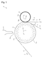
- FIG. 1 is a schematic view of a shaped sheet manufacturing apparatus.
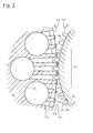
- FIG. 2 is an enlarged sectional view of a main part of the shaped sheet manufacturing apparatus.
- FIG. 3 is an explanatory diagram of the process of shaping.
- FIG. 4 is a plan view showing a bonding pattern.
- FIG. 5 is a plan view showing a bonding pattern.
- FIG. 6 is a plan view showing a bonding pattern.
- FIG. 7 is a plan view showing a bonding pattern.
- FIG. 8 is a photograph of the shaped sheet.
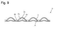
- FIG. 9 is a sectional view of the shaped sheet.
- FIG. 10 is an explanatory diagram of a method for manufacturing a shaped sheet.
- FIG. 11 is an explanatory diagram of a method for manufacturing a shaped sheet.
- Conventional example 2 is an enlarged sectional view of a main part of the shaped sheet manufacturing apparatus.
- FIG. 3 is an explanatory diagram of the process of shaping.
- FIG. 4
- Example 1 A method for manufacturing the shaped sheet of Example 1 will be described with reference to FIGS. 1 to 9.
- FIG. 1 is a schematic view of a shaping sheet manufacturing apparatus 10 used in the method of manufacturing a shaping sheet according to the first embodiment.
- FIG. 2 is an enlarged cross-sectional view of a main part of the shaping sheet manufacturing apparatus 10.
- the shaping sheet manufacturing apparatus 10 includes first and second rolls 12 and 14 arranged adjacent to each other and a first roll 12 arranged adjacent to each other. And a joining device 16.
- the first roll 12 has a cylindrical outer peripheral surface 12s having a plurality of recesses 12b (see FIG. 2) receding radially inward from the outer peripheral surface 12s.
- the second roll 14 has, on the cylindrical outer peripheral surface 14s, a plurality of convex portions 14a protruding radially outward from the outer peripheral surface 14s.
- the first and second rolls 12 and 14 rotate in synchronization with each other in opposite directions as indicated by arrows 12r and 14r, and the concave portion 12b of the first roll 12 and the convex portion 14a of the second roll 14 are separated from each other.
- the meshing region 13 is configured to be meshed with a gap, that is, without being in contact with each other.
- the concave portions 12b and the convex portions 14a are preferably two-dimensionally arranged on the outer peripheral surfaces 12s and 14s of the first and second rolls 12 and 14 so as to be meshed with each other at a plurality of positions at intervals.
- the continuous first sheet 2 is wound around the outer peripheral surface 12 s of the first roll 12, and the continuous second sheet 4 is wound on the first sheet 2.
- the first and second sheets 2 and 4 that have been hung are conveyed in the directions indicated by arrows 3 and 5 as the first roll 12 rotates.
- the first and second sheets 2 and 4 pass between the first roll 12 and the second roll 14, at least the first sheet 2 is shaped, and then, When passing between the first roll 12 and the joining device 16, the first and second sheets 2, 4 are joined together.
- the completed shaped sheet 6 is separated from the first roll 12 as shown by an arrow 7 and conveyed to a subsequent step, and is used for a disposable wearing article such as a disposable diaper.
- the inside of the concave portion 12b of the first roll 12 may be heated, whereby the shaping is performed more reliably.
- a heater is provided inside the first roll 12 to heat the periphery of the recess 12b. The heating may be applied to both the first and second rolls 12,14.
- the first roll 12 is formed with suction passages 12c and 12d communicating with the bottom of the recess 12b and a seal protrusion 12x protruding radially outward from the outer peripheral surface 12s.
- the recess 12b of the first roll 12 is connected to the negative pressure source via the suction flow paths 12c and 12d.
- the first sheet 2 arranged along the outer peripheral surface 12s of the first roll 12 is adsorbed and held.
- the suction channels 12c and 12d and the seal projection 12x may be omitted.
- the convex portion 14a of the second roll 14 is formed, for example, in a truncated pyramid shape with a flat tip 14t.
- the shape of the convex portion 14a of the second roll 14 may be, for example, a rectangular parallelepiped shape or a cylindrical shape, other than the truncated pyramid shape.
- FIG. 1 illustrates a state in which the joining device 16 which is an ultrasonic sealing device is retracted from the first roll 12.
- the first and second sheets 2 and 4 are arranged between the horn tip 16a of the joining device 16 and the flat surface 12t (see FIG. 2) of the seal projection 12x of the first roll 12.
- the part sandwiched between is ultrasonically bonded.
- the joining device 16 may be a device for joining other than ultrasonic joining, for example, a welding device or a joining roll like the conventional examples 1 and 2.
- the first sheet 2 is conveyed along the outer peripheral surface 12s of the rotating first roll 12. This is the first step.
- first and second sheets 2 and 4 pass between the first roll 12 and the second roll 14, and the recess 12b of the first roll 12 and the second roll 14
- the second sheet 4 is stacked on the first sheet 2 and is conveyed together with the first sheet 2 so as to be sandwiched between the convex portion 14a. This is the second step.
- the tension of the first sheet 2 is made smaller than the tension of the second sheet 4.
- a shapeable sheet is used as at least the first sheet 2 of the first and second sheets 2 and 4.
- the first and second sheets 2 and 4 may be non-stretchable nonwoven fabrics or air-through nonwoven fabrics.
- the second sheet 4 when the second sheet 4 starts to overlap with the first sheet 2 in the meshing region 13 (see FIG. 2) that is the region where the recess 12b and the protrusion 14a mesh, It is easy to independently adjust the tensions of the second sheets 2 and 4.
- the second sheet 4 may be wound around the second roll 14 on the upstream side in the transport direction with respect to the meshing region 13 so that the second sheet 4 starts to overlap with the first sheet 2 in the meshing region 13.
- the shaped sheet 6 may be manufactured in some cases.
- the joining is arranged adjacent to the first roll 12 in a state where the portion of the first sheet 2 pushed into the concave portion 12b by the convex portion 14a remains in the concave portion 12b.
- the device 16 is used to bond the first and second sheets 2, 4 together.
- the first sheet 2 can be reliably joined to the second sheet 4 at a predetermined position around the portion pressed into the concave portion 12b by the convex portion 14a, and the shape of the shaped sheet 6 is stabilized. .
- FIG. 3 is an explanatory view conceptually showing the process of shaping.
- the first sheet 2 is wound around the outer peripheral surface 12 s of the first roll 12, and then, as shown in FIG. Sheets 4 of are stacked.
- the first and second sheets 2 and 4 In the meshing region 13 (see FIG. 2) where the concave portion 12b of the first roll 12 and the convex portion 14a of the second roll 14 mesh with each other, the first and second sheets 2 and 4 have a portion 2a facing the concave portion 12b. , 4a are pushed into the recess 12b by the projection 14a that meshes with the recess 12b. As a result, the first and second sheets 2 and 4 have the portions 2b and 4b pressed into the recess 12b.
- the first and second sheets 2 and 4 are elastically or plastically deformed.
- the downstream side the right side in FIG. 3B
- the relative movement of the first and second sheets 2 and 4 is restricted, and the convex movement is restricted.
- the upstream side left side in FIG. 3B
- the first and second sheets 2 and 4 are not restrained at all or almost at all. Therefore, the first and second sheets 2 and 4 are pulled out on the upstream side in the transport direction with respect to the concave portion 12b meshing with the convex portion 14a and are pushed into the concave portion 12b.
- the convex portion 14a that meshes with the concave portion 12b gradually comes out of the concave portion 12b, and the first and second sheets are formed around the concave portion 12b.
- the second sheets 2 and 4 gradually overlap.
- the tension of the first sheet 2 immediately before being sandwiched between the concave portion 12b and the convex portion 14a is T1
- the tension of the second sheet 4 immediately before is T2
- the tensions of the first and second sheets 2 and 4 are set so that T1 ⁇ T2.
- a well-known tension adjusting mechanism is provided on the upstream side of the meshing region 13 in the transport direction, and the tensions T1 and T2 are adjusted so that T1 ⁇ T2.
- T1 0, the portion 2b pushed into the recess 12b of the first sheet 2 remains in the recess 12b when passing through the meshing region 13. Even if T1 ⁇ 0, if T1 is small, for example, T1 ⁇ 0.05 N / mm, the friction between the first sheet 2 and the first roll 12 is overcome and the first sheet 2 is overcome. Cannot be pulled back to the upstream side in the transport direction. Also in this case, the portion 2b of the first sheet 2 that has been pushed into the recess 12b remains in the recess 12b.
- the tension T2 of the second sheet 4 is not more than the breaking strength of the second sheet 4, for example, 0.1 to 2 N / mm.
- the tension T2 of the second sheet 4 overcomes the frictional force between the first and second sheets 2 and 4, when the convex portion 14a meshing with the concave portion 12b then comes out of the concave portion 12b, The portion 4b of the sheet 4 pushed into the recess 12b gradually comes out of the recess 12b.
- the portion 4x on the downstream side in the transport direction with respect to the convex portion 14a is pulled and plastically deformed to extend. Even if 14a goes out of the concave portion 12b, it still extends.
- the second sheet 4 is simultaneously pushed into the plurality of recesses 12b adjacent to each other in the direction orthogonal to or intersecting the transport direction, and the portion between the recesses 12b adjacent in the direction orthogonal to or intersecting the transport direction is pulled.
- the plastically deformed and elongated the plastically deformed portion remains elongated even if the convex portion 14a goes out of the concave portion 12b.
- the portion 2b pressed into the concave portion 12b is covered with the second sheet 4 and does not contact the convex portion 14a. Therefore, the tension T1 of the first sheet 2 is changed to the tension of the second sheet 4. Even if it is smaller than T2, the portion 2b pressed into the recess 12b of the first sheet 2 does not get caught in the protrusion 14a and come off from the recess 12b. Therefore, even if the tension T1 of the first sheet 2 is reduced, the first sheet 2 can be reliably shaped.
- both the first and second sheets 2 and 4 can be shaped at the same time, but in addition to the roll for shaping the first sheet 2, a roll for shaping the second sheet 4 can be formed. No need to prepare. Therefore, both the first and second sheets 2 and 4 can be shaped without complicating the configuration of the shaping sheet manufacturing apparatus 10.
- the shaped sheet 6 corresponds to a portion 2c (see FIG. 3C) of the first sheet 2 which is pushed into the concave portion 12b by the convex portion 14a and remains in the concave portion 12b (see FIG. 3C). Is formed.
- FIG. 9 is a cross-sectional view of the shaped sheet 6 manufactured by the above method.
- FIG. 9 conceptually shows an example of a cross section of the shaped sheet 6 in a natural state where no tension is applied to the first and second sheets 2 and 4.
- the first and second sheets 2 and 4 are formed with raised portions 2x and 4x that are raised on the same side.
- the raised portion 2s of the first sheet 2 is larger than the raised portion 4x of the second sheet 4, and a space 6x is formed between the first and second sheets 2 and 4.
- the first and second sheets 2 and 4 are joined to each other at the joint portion 8x.
- an arrow 8 indicates a direction in which the first and second sheets 2 and 4 are conveyed (hereinafter, referred to as “flow direction”).
- the + symbol indicates the vicinity of the center of the raised portion of the first sheet 2 formed on the first sheet 2.
- the joint portion where the first and second sheets 2 and 4 are joined to each other is formed corresponding to the flat surface 12t (see FIG. 2) of the seal projection 12x of the first roll 12.
- a plurality of crescent-shaped joining portions 30 and 31 that are curved on opposite sides are alternately arranged at intervals in the flow direction.
- the raised portion is formed between the joint portions 30 and 31 whose concave sides are opposed to each other.
- the plurality of rows in which the joint portions 30 and 31 are arranged in the flow direction are the regions 20 in which the concave sides of the joint portions 30 and 31 face each other, and the pairs 22 in which the convex sides of the joint portions 30 and 31 face each other 22.
- the pitch is shifted so as to be sandwiched between the joining portions 30 and 31 of 24.
- a rectangular joining portion 32 is arranged at each apex of a plurality of virtual rectangles in which one diagonal line is parallel to the flow direction and arranged without a gap.
- the raised portion is formed inside the virtual rectangle.
- the chain line indicates one of the virtual rectangles.
- linear joining portions 34 are arranged on each side of a plurality of virtual rectangles in which one diagonal line is parallel to the flow direction and are lined up without a gap, and three joining points are formed at the three vertices of the virtual rectangle.
- a substantially cruciform joining portion 36 is arranged in each case, and four circular joining portions 35 are arranged so as to surround another vertex of the virtual rectangle.
- the raised portion is formed inside the virtual rectangle.
- the chain line indicates one of the virtual rectangles.
- four circular joining portions 40 are arranged so that one diagonal line is parallel to the flow direction and surrounds the vertices of a plurality of virtual rectangles that are aligned without a gap. .
- the raised portion is formed inside the virtual rectangle.
- the chain line indicates one of the virtual rectangles.
- a bone-shaped joining portion 42 is arranged at each apex of a plurality of virtual rectangles in which one diagonal line is parallel to the flow direction and arranged without a gap.
- the raised portion is formed inside the virtual rectangle.
- the chain line indicates one of the virtual rectangles.
- five circular joining portions 40 are arranged at and around each apex of a plurality of virtual rectangles in which one diagonal line is parallel to the flow direction and are aligned without gaps. .
- the raised portion is formed inside the virtual rectangle.
- the joint 40 surrounding the ridge is arranged in a diamond shape.
- the chain line indicates one of the virtual rectangles.
- a circular joining portion 46 is arranged at each apex of a plurality of virtual hexagons in which a pair of opposite sides are parallel to the flow direction and are lined up without a gap.
- the raised portion is formed inside the virtual hexagon.
- the chain line shows one of the virtual hexagons.
- a circular joining portion 48 is arranged at each apex of a plurality of virtual octagons whose two pairs of opposing sides are parallel or perpendicular to the flow direction.
- the virtual octagon is lined up with a plurality of virtual rectangles whose opposite sides are parallel or perpendicular to the flow direction without any gap.
- the raised portion is formed inside the virtual octagon.
- the chain line shows one of the virtual octagons and four virtual rectangles adjacent to it.
- FIG. 8 is a photograph of the shaped sheet 6 prototyped using the shaped sheet manufacturing apparatus 10.
- a non-woven fabric sheet having elasticity in a direction perpendicular to the flow direction is used for the first and second sheets 2 and 4, and the first and second sheets 2 and 4 are joined as shown in FIG. Joined in a pattern.
- FIG. 8 (a) is a photograph of the first sheet 2 side. From FIG. 8A, it can be seen that the raised portion is formed on the first sheet 2.
- FIG. 8B is a photograph of the second sheet 4 side. It can be seen from FIG. 8B that the second sheet 4 is slightly recessed.
- Shaped sheet 10 Manufacturing apparatus of a shaped sheet 12 1st roll 12b Recess 12s Outer peripheral surface 13 Interlocking area 14 Second roll 14a Convex part 14s Outer peripheral surface 16 Joining device
Landscapes
- Engineering & Computer Science (AREA)
- Health & Medical Sciences (AREA)
- Textile Engineering (AREA)
- Animal Behavior & Ethology (AREA)
- Vascular Medicine (AREA)
- Manufacturing & Machinery (AREA)
- Veterinary Medicine (AREA)
- Epidemiology (AREA)
- Biomedical Technology (AREA)
- Heart & Thoracic Surgery (AREA)
- Public Health (AREA)
- Life Sciences & Earth Sciences (AREA)
- General Health & Medical Sciences (AREA)
- Mechanical Engineering (AREA)
- Physics & Mathematics (AREA)
- Fluid Mechanics (AREA)
- Absorbent Articles And Supports Therefor (AREA)
- Shaping Of Tube Ends By Bending Or Straightening (AREA)
- Lining Or Joining Of Plastics Or The Like (AREA)
Abstract
Priority Applications (5)
| Application Number | Priority Date | Filing Date | Title |
|---|---|---|---|
| US17/281,151 US11351768B2 (en) | 2018-10-24 | 2019-10-24 | Shaped sheet manufacturing method |
| BR112021006334-0A BR112021006334B1 (pt) | 2018-10-24 | 2019-10-24 | Método de fabricação de folha moldada |
| EP19875514.2A EP3871870B1 (fr) | 2018-10-24 | 2019-10-24 | Procédé de fabrication de feuille façonnée |
| JP2020552609A JP7236457B2 (ja) | 2018-10-24 | 2019-10-24 | 賦形シートの製造方法 |
| CN201980065793.6A CN112805139B (zh) | 2018-10-24 | 2019-10-24 | 成形片材的制造方法 |
Applications Claiming Priority (2)
| Application Number | Priority Date | Filing Date | Title |
|---|---|---|---|
| JP2018-200202 | 2018-10-24 | ||
| JP2018200202 | 2018-10-24 |
Publications (1)
| Publication Number | Publication Date |
|---|---|
| WO2020085460A1 true WO2020085460A1 (fr) | 2020-04-30 |
Family
ID=70330448
Family Applications (1)
| Application Number | Title | Priority Date | Filing Date |
|---|---|---|---|
| PCT/JP2019/041790 Ceased WO2020085460A1 (fr) | 2018-10-24 | 2019-10-24 | Procédé de fabrication de feuille façonnée |
Country Status (6)
| Country | Link |
|---|---|
| US (1) | US11351768B2 (fr) |
| EP (1) | EP3871870B1 (fr) |
| JP (1) | JP7236457B2 (fr) |
| CN (1) | CN112805139B (fr) |
| BR (1) | BR112021006334B1 (fr) |
| WO (1) | WO2020085460A1 (fr) |
Citations (6)
| Publication number | Priority date | Publication date | Assignee | Title |
|---|---|---|---|---|
| JPH06255006A (ja) * | 1992-12-29 | 1994-09-13 | Kimberly Clark Corp | ストレッチによってピロー部を形成した嵩のある積層材料及びその製造方法 |
| JP4090420B2 (ja) | 2002-11-13 | 2008-05-28 | 花王株式会社 | 吸収性物品用の表面シート |
| JP2009126107A (ja) * | 2007-11-26 | 2009-06-11 | Kao Corp | 複合シート |
| WO2014084066A1 (fr) * | 2012-11-30 | 2014-06-05 | 株式会社瑞光 | Matériau de feuille composite et vêtement jetable, et procédé et dispositif de fabrication du matériau de feuille composite |
| JP2016087423A (ja) * | 2015-06-04 | 2016-05-23 | ユニ・チャーム株式会社 | 凹凸シートの製造方法、及び、凹凸シートの製造装置 |
| WO2016199543A1 (fr) | 2015-06-08 | 2016-12-15 | 株式会社瑞光 | Feuille composite, et dispositif et procédé de fabrication de feuille composite |
Family Cites Families (9)
| Publication number | Priority date | Publication date | Assignee | Title |
|---|---|---|---|---|
| TW343148B (en) * | 1996-03-19 | 1998-10-21 | Kao Corp | Composite sheet, absorbent article and process for producing the same |
| US20020023708A1 (en) * | 1999-05-14 | 2002-02-28 | Industrie Cartarie Tronchetti | Method and apparatus for embossing sheet materials such as paper webs and diaper backsheets |
| US7468114B2 (en) | 2002-11-13 | 2008-12-23 | Kao Corporation | Composite sheet and process and apparatus for producing the same |
| US7314663B2 (en) * | 2003-09-29 | 2008-01-01 | The Procter + Gamble Company | Embossed multi-ply fibrous structure product and process for making same |
| TWI504385B (zh) * | 2012-07-18 | 2015-10-21 | Kang Na Hsiung Entpr Co Ltd | A guide sheet for an absorbent article, a method for producing the same, and a molding die |
| AU2014351467B2 (en) * | 2013-11-20 | 2018-10-04 | Kimberly-Clark Worldwide, Inc. | Absorbent article containing a soft and durable backsheet |
| ITUB20153482A1 (it) * | 2015-09-08 | 2015-12-08 | Fameccanica Data Spa | Nastro composito tridimensionale, procedimento ed apparecchio per la sua produzione |
| CN108095903A (zh) * | 2018-01-26 | 2018-06-01 | 厦门延江新材料股份有限公司 | 一种立体透气片材及吸收制品 |
| CN108481986A (zh) * | 2018-04-23 | 2018-09-04 | 佛山市南海区志胜激光制辊有限公司 | 一种双层点对点无胶复合压花系统及其复合压花纸 |
-
2019
- 2019-10-24 BR BR112021006334-0A patent/BR112021006334B1/pt active IP Right Grant
- 2019-10-24 JP JP2020552609A patent/JP7236457B2/ja active Active
- 2019-10-24 EP EP19875514.2A patent/EP3871870B1/fr active Active
- 2019-10-24 US US17/281,151 patent/US11351768B2/en active Active
- 2019-10-24 WO PCT/JP2019/041790 patent/WO2020085460A1/fr not_active Ceased
- 2019-10-24 CN CN201980065793.6A patent/CN112805139B/zh active Active
Patent Citations (6)
| Publication number | Priority date | Publication date | Assignee | Title |
|---|---|---|---|---|
| JPH06255006A (ja) * | 1992-12-29 | 1994-09-13 | Kimberly Clark Corp | ストレッチによってピロー部を形成した嵩のある積層材料及びその製造方法 |
| JP4090420B2 (ja) | 2002-11-13 | 2008-05-28 | 花王株式会社 | 吸収性物品用の表面シート |
| JP2009126107A (ja) * | 2007-11-26 | 2009-06-11 | Kao Corp | 複合シート |
| WO2014084066A1 (fr) * | 2012-11-30 | 2014-06-05 | 株式会社瑞光 | Matériau de feuille composite et vêtement jetable, et procédé et dispositif de fabrication du matériau de feuille composite |
| JP2016087423A (ja) * | 2015-06-04 | 2016-05-23 | ユニ・チャーム株式会社 | 凹凸シートの製造方法、及び、凹凸シートの製造装置 |
| WO2016199543A1 (fr) | 2015-06-08 | 2016-12-15 | 株式会社瑞光 | Feuille composite, et dispositif et procédé de fabrication de feuille composite |
Non-Patent Citations (1)
| Title |
|---|
| See also references of EP3871870A4 |
Also Published As
| Publication number | Publication date |
|---|---|
| CN112805139A (zh) | 2021-05-14 |
| BR112021006334B1 (pt) | 2024-03-12 |
| EP3871870A4 (fr) | 2021-12-01 |
| US20210339521A1 (en) | 2021-11-04 |
| CN112805139B (zh) | 2023-01-10 |
| JPWO2020085460A1 (ja) | 2021-09-24 |
| EP3871870A1 (fr) | 2021-09-01 |
| EP3871870B1 (fr) | 2023-01-11 |
| JP7236457B2 (ja) | 2023-03-09 |
| US11351768B2 (en) | 2022-06-07 |
| BR112021006334A2 (pt) | 2021-07-06 |
Similar Documents
| Publication | Publication Date | Title |
|---|---|---|
| JP6467508B2 (ja) | 複合伸縮部材の製造装置および製造方法 | |
| CN105705124B (zh) | 吸收体及其制造设备 | |
| JP5980949B2 (ja) | 複合シート材とこれを用いた使い捨て着用物品および複合シート材の製造方法と製造装置 | |
| JP6625126B2 (ja) | 複合伸縮部材、着用物品および着用物品の製造方法 | |
| JP4934835B2 (ja) | 積層伸縮シートの製造方法 | |
| JP5961477B2 (ja) | 複合シートの製造方法 | |
| JP7353739B2 (ja) | 伸縮性シートの製造方法、伸縮性シートの製造装置、及び、伸縮性シート | |
| JP2020054742A (ja) | 伸縮性シートの製造方法、及び、伸縮性シートの製造装置 | |
| JP6660456B2 (ja) | 複合シート並びに複合シートの製造装置及び製造方法 | |
| JP2020054741A (ja) | 伸縮性シートの製造方法、及び、伸縮性シートの製造装置 | |
| TWI708596B (zh) | 吸收性物品相關之複數薄片的固定裝置及固定方法 | |
| JP5901440B2 (ja) | 使い捨ての着用物品 | |
| WO2020085460A1 (fr) | Procédé de fabrication de feuille façonnée | |
| JP6384361B2 (ja) | ファスニングテープの製造方法,テープ型の使い捨ておむつの製造方法,ファスニングテープ,及びテープ型の使い捨ておむつ | |
| CN114829115B (zh) | 伸缩性复合片的制造方法和制造装置 | |
| JP5222539B2 (ja) | 立体複合シートの製造装置 | |
| JP7187239B2 (ja) | 伸縮性シートの製造方法、及び、伸縮性シートの製造装置 | |
| JP7212432B2 (ja) | 伸縮性シートの製造方法 | |
| JP7383768B2 (ja) | 伸縮性シート | |
| JP7322676B2 (ja) | テープ製造方法およびテープ製造装置 |
Legal Events
| Date | Code | Title | Description |
|---|---|---|---|
| 121 | Ep: the epo has been informed by wipo that ep was designated in this application |
Ref document number: 19875514 Country of ref document: EP Kind code of ref document: A1 |
|
| ENP | Entry into the national phase |
Ref document number: 2020552609 Country of ref document: JP Kind code of ref document: A |
|
| REG | Reference to national code |
Ref country code: BR Ref legal event code: B01A Ref document number: 112021006334 Country of ref document: BR |
|
| NENP | Non-entry into the national phase |
Ref country code: DE |
|
| ENP | Entry into the national phase |
Ref document number: 2019875514 Country of ref document: EP Effective date: 20210525 |
|
| ENP | Entry into the national phase |
Ref document number: 112021006334 Country of ref document: BR Kind code of ref document: A2 Effective date: 20210401 |