WO2020085507A1 - Machine à courant continu - Google Patents
Machine à courant continu Download PDFInfo
- Publication number
- WO2020085507A1 WO2020085507A1 PCT/JP2019/042022 JP2019042022W WO2020085507A1 WO 2020085507 A1 WO2020085507 A1 WO 2020085507A1 JP 2019042022 W JP2019042022 W JP 2019042022W WO 2020085507 A1 WO2020085507 A1 WO 2020085507A1
- Authority
- WO
- WIPO (PCT)
- Prior art keywords
- coil
- coils
- rotor
- transistor
- transistors
- Prior art date
- Legal status (The legal status is an assumption and is not a legal conclusion. Google has not performed a legal analysis and makes no representation as to the accuracy of the status listed.)
- Ceased
Links
Images


Classifications
-
- H—ELECTRICITY
- H02—GENERATION; CONVERSION OR DISTRIBUTION OF ELECTRIC POWER
- H02K—DYNAMO-ELECTRIC MACHINES
- H02K11/00—Structural association of dynamo-electric machines with electric components or with devices for shielding, monitoring or protection
- H02K11/30—Structural association with control circuits or drive circuits
- H02K11/33—Drive circuits, e.g. power electronics
-
- H—ELECTRICITY
- H02—GENERATION; CONVERSION OR DISTRIBUTION OF ELECTRIC POWER
- H02K—DYNAMO-ELECTRIC MACHINES
- H02K29/00—Motors or generators having non-mechanical commutating devices, e.g. discharge tubes or semiconductor devices
-
- H—ELECTRICITY
- H02—GENERATION; CONVERSION OR DISTRIBUTION OF ELECTRIC POWER
- H02M—APPARATUS FOR CONVERSION BETWEEN AC AND AC, BETWEEN AC AND DC, OR BETWEEN DC AND DC, AND FOR USE WITH MAINS OR SIMILAR POWER SUPPLY SYSTEMS; CONVERSION OF DC OR AC INPUT POWER INTO SURGE OUTPUT POWER; CONTROL OR REGULATION THEREOF
- H02M7/00—Conversion of AC power input into DC power output; Conversion of DC power input into AC power output
- H02M7/42—Conversion of DC power input into AC power output without possibility of reversal
- H02M7/44—Conversion of DC power input into AC power output without possibility of reversal by static converters
- H02M7/48—Conversion of DC power input into AC power output without possibility of reversal by static converters using discharge tubes with control electrode or semiconductor devices with control electrode
-
- H—ELECTRICITY
- H02—GENERATION; CONVERSION OR DISTRIBUTION OF ELECTRIC POWER
- H02P—CONTROL OR REGULATION OF ELECTRIC MOTORS, ELECTRIC GENERATORS OR DYNAMO-ELECTRIC CONVERTERS; CONTROLLING TRANSFORMERS, REACTORS OR CHOKE COILS
- H02P6/00—Arrangements for controlling synchronous motors or other dynamo-electric motors using electronic commutation dependent on the rotor position; Electronic commutators therefor
- H02P6/14—Electronic commutators
-
- Y—GENERAL TAGGING OF NEW TECHNOLOGICAL DEVELOPMENTS; GENERAL TAGGING OF CROSS-SECTIONAL TECHNOLOGIES SPANNING OVER SEVERAL SECTIONS OF THE IPC; TECHNICAL SUBJECTS COVERED BY FORMER USPC CROSS-REFERENCE ART COLLECTIONS [XRACs] AND DIGESTS
- Y02—TECHNOLOGIES OR APPLICATIONS FOR MITIGATION OR ADAPTATION AGAINST CLIMATE CHANGE
- Y02T—CLIMATE CHANGE MITIGATION TECHNOLOGIES RELATED TO TRANSPORTATION
- Y02T10/00—Road transport of goods or passengers
- Y02T10/60—Other road transportation technologies with climate change mitigation effect
- Y02T10/64—Electric machine technologies in electromobility
Definitions
- the present invention relates to a DC machine.
- DC machines because DC motors have excellent speed control, they have traditionally been used for large electric vehicles and cranes, and for small electric tools and automobile electrical equipment.
- a DC motor is equipped with a brush and a commutator (commutator). When the motor is operating, the brush is pressed against the rectifier and wear occurs. Therefore, maintenance of the brush and commutator is indispensable.
- electrical noise and mechanical noise are generated due to the mechanical switch.
- a brushless motor has been developed that replaces the brush and commutator with an inverter circuit and realizes the removal of the brush and commutator.
- This brushless motor is widely used not only in industrial electric motors, but also in home appliances and office equipment (see Patent Document 1).
- many brushless motors that are currently in practical use are synchronous motors that include three-phase coils, and are not intended to make a DC motor that includes a large number of commutator pieces non-contact.
- the most basic brushless motor is, as shown in FIG. 29, a three-phase bridge circuit composed of six transistors T1 to T6 forming three half bridges connected to a DC power supply 60, a three-phase motor U, V and W phase coils are connected.
- This brushless motor includes a magnet rotor, and the control circuit 50 ′ sequentially switches the switching of each transistor based on the position of the magnet rotor to drive the three-phase coils U, V, and W by 120 degrees.
- the magnet rotor is rotated by driving by energization angle control called 180-degree energization drive.
- the transistors of all the phases of the three-phase bridge circuit are repeatedly turned on for 120 degrees and turned off for 60 degrees.
- each transistor is repeatedly turned on and off at intervals of 180 degrees. Then, the switching timings of the transistors connected to the coils U, V, W of the respective phases are shifted by 120 degrees in electrical angle to supply the phase-shifted currents to the coils U, V, W of the respective phases. is doing.
- the winding of each phase may be subjected to sine wave drive by PWM.
- a brushless motor with a three-phase coil is, in principle, the same as a three-phase permanent magnet synchronous motor that uses an inverter to supply a three-phase alternating current to each coil. Therefore, a brushless motor having a three-phase coil does not constitute a DC motor having a large number of commutator pieces as a non-commutator motor or a brushless motor, simply because the power source is a DC power source. Therefore, there is a problem that the current flowing through each coil has a period during which it is zero in the most general 120-degree conduction drive, and the utilization factor of the current flowing through the coil is low. Further, even when the sine wave drive is performed, the current flowing through the coil increases and decreases in a sine wave shape, so that the utilization rate of the current that can be passed through the coil is lower than when direct current is passed.
- the present invention has been made in view of these circumstances, and by making a DC machine having a large number of commutator pieces non-commutator or brushless, the current utilization rate of a coil equivalent to that of a brushed DC motor is improved.
- the purpose is to provide a high DC machine.
- a first technical means of the present invention is a direct current machine, which is a rotor of 2 m poles (m is an integer) having magnetic poles of N poles and S poles, and magnetic poles of the rotors.
- the stator has a coil pitch that is approximately equal to the pitch, and has n coils that are provided with a phase shift of 2 ⁇ / n (n is an integer of 4 m or more), and each of the coils has two leads.
- Each of the output lines has a line at the connection point of the two switching elements of the half bridge composed of two switching elements connected to the positive side power source line and the negative side power source line of the DC power source.
- each coil is the coil side of the coil facing the N pole of the rotor and the coil side of the coil facing the S pole. So that the switching elements are in different directions. It is characterized in further comprising a control circuit for switching the conduction and non-conduction.
- the first technical means when an electric current is applied to the two adjacent coils, magnetic fields in the same direction are generated in a region surrounded by the two coils in common.
- the output lines of the adjacent coils are sequentially connected, the coils are connected in series in an annular shape, and the connection point of the output lines is connected to the connection point of the two switching elements of the half bridge. It is characterized by.
- a third technical means is the same as the first technical means, wherein the two lead wires of each coil are not connected to the other lead wires of the other coils, and the two lead wires of the half bridge are respectively connected.
- One of the switching elements is connected to the connection point.
- the number of the coils is an even number, and when an electric current is applied to two adjacent coils, in a region surrounded by the two coils in common,
- the output lines of the adjacent coils are sequentially connected so that the coils are connected in series in a ring shape so that a magnetic field in the opposite direction is generated, and each connection point of the output lines is connected to two of the half bridges. It is characterized in that it is connected to the connection point of the switching element.
- a fifth technical means is the first technical means, wherein the number of the coils is an odd number, and when a current is passed through the two adjacent coils, in a region surrounded by the two coils in common, The output lines of the adjacent coils are sequentially connected and the coils are connected in series so that a magnetic field in the opposite direction is generated, and each connection point of the output lines has two switching points of the half bridge. It is characterized in that it is connected to the connection point of the element.
- a sixth technical means is the same as the first technical means, wherein the number of the coils is an even number, and the two adjacent coils are divided into a coil pair in which one of the two coils forming the coil pair is divided.
- the output lines of the two coils are connected so that magnetic fields in opposite directions are generated in a region commonly surrounded by the two coils when an electric current is applied from the two coils to the other coil.
- the connection points of the two lead wires of the half bridge are respectively connected to the connection points of the lead wires of the two coils of the pair and the lead wires of both ends. is there.
- the number of the coils is an odd number
- the two adjacent coils are divided into a coil pair in which two adjacent coils are connected in series and one independent coil to form the coil pair.
- the output lines of the two coils are connected so that when an electric current is applied from one of the two coils to the other, a magnetic field in the opposite direction is generated in a region commonly surrounded by the two coils.
- the connection point of the output lines of the two coils of the coil pair and the output lines of both ends are respectively connected to the connection points of the two switching elements of the half bridge, and the single coil The output lines at both ends of the are respectively connected to the connection points of the half bridge.
- An eighth technical means is the technical means according to any one of the first to seventh technical means, wherein the control circuit does not apply a current to the coil side facing near the boundary between the N pole and the S pole of the rotor. In this way, the switching element is switched between conducting and non-conducting.
- the ninth technical means is characterized in that, in any one of the first to eighth technical means, each of the coils is inserted into a slot formed in the stator.
- the tenth technical means is the technical means according to any one of the first to ninth technical features, characterized in that the rotor is a permanent magnet rotor or a rotor having an exciting coil.
- a DC machine having a large number of commutator pieces can be provided with a motor having a high coil current utilization rate, which is equivalent to that of a brushed DC motor, for making the DC machine non-commutator or brushless.
- the torque is large at low speed from the start, the rotation speed can be controlled by the voltage, and a DC machine without electric noise can be obtained.
- FIG. 2 is a diagram showing development of a switching circuit and a stator winding of the DC motor shown in FIG. 1.
- 3 is an equivalent circuit excluding the position detection sensor and the control circuit of the DC motor according to the first embodiment of the present invention. It is a figure which shows one structural example of the control circuit of the direct-current motor which concerns on the 1st Embodiment of this invention. It is a figure which shows the transition of the ON / OFF state of the switching element of the DC motor which concerns on the 1st Embodiment of this invention.
- a preferred embodiment of a DC machine of the present invention will be described below with reference to the drawings, taking a DC motor as an example.
- the same reference numerals are used in the different drawings, and the description thereof may be omitted.
- the present invention is not limited to the examples in these embodiments, and includes all modifications within the scope and equivalents of the matters described in the claims.
- an inner rotor type DC motor having slots formed in the stator will be described as an example, but the DC motor of the present invention is a slotless motor, an outer rotor type motor, or an axial gap type motor. It may be configured as a DC motor.
- the DC motor described below functions as a generator as well as the conventional brush DC motor, and its structure is similar to that of the DC motor.
- FIG. 1 is a diagram showing an outline of a DC motor according to a first embodiment of the present invention
- FIG. 2 is a diagram showing only a switching circuit and a stator winding of the DC motor shown in FIG.
- FIG. 3 is an equivalent circuit excluding the position detection sensor and the control circuit of the DC motor according to the first embodiment of the present invention.
- the DC motor 101 includes a stator 10, a rotor 20, a switching circuit 30, a position detection sensor 40, and a control circuit 50.
- a DC power supply 60 is connected to the switching circuit 30.
- the stator winding of the present invention has two layers. In the following description, for example, the symbol “A” is used for both the “coil A” and the “coil side A", but as shown in FIGS. 1 and 2, the "coil A” is the rotor 20.
- coil side A Means a coil side A and a coil side a which are housed in two slots separated by a magnetic pole pitch, a coil end connecting these two coil sides A and a, and two lead wires.
- coil side A indicates one of the two coil sides of the coil A. The same applies to the other coils B to I.
- the coil side is a coil portion where the magnetic force lines of the magnetic field of the rotor 20 intersect at right angles.
- the coil sides of the nine coils A to I are stored in slots with a phase difference of 2 ⁇ / n.
- the number of coils n is odd, the number of slots is also odd.
- the respective coil sides of the nine coils A to I are within the slot accommodating one coil side and the magnetic pole pitch of the rotor 20 from this slot (180 ° because it is a two-pole machine in this embodiment).
- the other coil side is housed in the slot closest to the magnetic pole pitch.
- the magnetic pole pitch of the rotor means an interval (angle) between adjacent magnetic poles of the rotor.
- the magnetic pole pitch is 90 °.
- the two coil sides of each coil are placed in slots at positions 180 ° apart. That is, when the number of slots is an even number, full-pitch winding is performed and the coil pitch becomes equal to the magnetic pole pitch.
- the number of slots is an odd number, it is a short pitch winding, and the coil pitch is shorter than the magnetic pole pitch, but is provided so as to be closest to the magnetic pole pitch.
- the coil pitch is substantially equal to the magnetic pole pitch of the rotor, including both the case where the coil pitch is equal to the magnetic pole pitch and the case where it is shorter than the magnetic pole pitch but closest to the magnetic pole pitch.
- the DC motor shown in FIG. 1 corresponds to a brushed DC motor having a two-pole rotor, coils A to I housed in nine slots, and nine commutator pieces.
- the coil A has a slot in which the coil side A is accommodated and a coil side a which is accommodated in four slots separated from this slot.
- the coil B has a coil side B accommodated in a slot adjacent to a slot in which the coil side A is accommodated and a coil side b accommodated in a slot separated by four slots from this slot.
- the coil C has a coil side C accommodated in a slot adjacent to a slot in which the coil side B is accommodated and a coil side c accommodated in a slot separated by four slots from this slot.
- the coil I is housed in the coil side I housed in the slot adjacent to the slot in which the coil side H is housed and in the slots separated by four slots from this slot.
- Coil side i is housed in the coil side I housed in the slot adjacent to the slot in which the coil side H is housed and in the slots separated by four slots from this slot.
- the coil side G and the coil side c, the coil side H and the coil side d, and the coil side I and the coil side e are housed in the same slot.
- each of the nine coils A to I is connected in series, forming an annular closed loop as a whole.
- the connection point of each coil is connected to the plus-side power supply line 61 and the minus-side power supply line 62 of the DC power supply 60 via a transistor that is a switching element.
- the lead wire on the coil side i side of the coil I and the lead wire on the coil side A side of the coil A adjacent to the coil I are connected, and the connection point is connected to the plus side power supply line 61 via the transistor TA1.
- the transistor TA2 is connected to the minus power supply line 62 via the transistor TA2.
- the output line on the coil side a of the coil A and the output line on the coil side B of the coil B adjacent to the coil A are connected, and the connection point is connected to the plus side power supply line 61 via the transistor TB1.
- And is connected to the minus power supply line 62 via the transistor TB2.
- the adjacent coils when a current is applied to two adjacent coils, the adjacent coils are arranged so that magnetic fields in the same direction are generated in a region surrounded by the two coils in common.
- the output lines are sequentially connected, and the coils are connected in series in a ring shape.
- the magnetic flux generated in the coils B and C when the current flows from the output line of the coil side B to the output line of the coil side c is two coils.
- a magnetic field in the same direction is generated in a region surrounded by B and C in common.
- This type of coil connection is referred to as forward connection in the present invention.
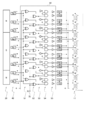
- the switching circuit 30 includes nine transistors TA1 to TI1 on the positive power supply side connected to the positive power supply line 61 and nine transistors TA2 to TI2 on the negative power supply side connected to the negative power supply line 62.
- the nine transistors TA1 to TI1 on the positive power source side and the nine transistors TA2 to TI2 on the negative power source side form a pair to form a half bridge.
- each coil A to I has a stator winding structure similar to the lap winding in the DC motor.
- the rotor 20 shown in FIG. 1 is rotatably provided around a shaft (not shown), and is provided with a permanent magnet in this embodiment.
- the rotor 20 is not limited to the permanent magnet rotor, and may include an exciting coil.
- the number of poles of the rotor 20 is two in this embodiment, but it may be more than two.
- the lead wire of the coil at the symmetrical position of 180 ° may be connected to the connection point of the two transistor elements of the same half bridge.
- the sensors Sa to Si are used. In FIG. 1, the sensors Sa to Si are shown to be located at the slots of the stator 10, but in practice, they may be provided at positions axially separated from the stator 10.
- the sensors Sa to Si, which are Hall elements, are an example of detecting the magnetic field of the rotor 20, and although the components are small and the configuration is simple, a sensor using a saturable coil or the position of the rotor 20 is detected without contact. If possible, an absolute encoder with a photodetector may be used.
- the sensors Sa to Si are adjusted so as to output a logical value “H” when the north poles of the rotor 20 face each other and output a logical value “L” when the south poles face each other. Has been done.
- a resolver may be used to detect the position of the rotor 20. In this case, the rotation angle of the rotor 20 will be calculated.
- the control circuit 50 receives the position signal of the rotor 20 from the position detection sensor 40, and is connected to the transistors TA1 to TI1 connected to the positive power supply line 61 of the switching circuit 30 and the negative power supply line 62. By switching the on / off states of the transistors TA2 to TI2, the directions of the currents flowing through the coils A to I are switched. In the present embodiment, as will be described later, any one of the transistors TA1 to TI1 and any one of the transistors TA2 to TI2 are turned on.
- FIG. 4 is a diagram showing an example of the configuration of the control circuit of the DC motor according to the first embodiment of the present invention.
- the control circuit 50 shown in FIG. 4 receives the signals from the nine sensors Sa to Si and sends on / off signals to the gates of the eighteen transistors TA1 to TI2 that are switching elements.
- the logic circuit configuring the control circuit 50 has nine XORs (exclusive ORs) of the first stage 51 shown in FIG.
- two adjacent hall elements for example, a sensor
- the signals from Sc and Sd are input to the XOR circuit of the first stage 51, and the outputs thereof are input to the AND circuits forming a pair of the fourth stage 54 connected to the transistors TD1 and TD2.
- the signal from the sensor Sc and the forward / reverse signal Q from the forward / reverse rotation control input terminal 70 are input to the XOR circuit of the second stage 52, and the output thereof is the AND circuit of the fourth stage 54 forming a pair.
- the sensors Sa to Si are arranged at predetermined positions so that torque is applied to the rotor 20 when a current is passed through the coils A to I by switching each transistor.
- the N pole of the rotor 20 faces the sensors Se, Sf, Sg, Sh, Si
- the S pole of the rotor 20 faces the sensors Sa, Sb, Sc, Sd (hereinafter, this state "Case 1")
- the outputs of the sensors Se, Sf, Sg, Sh, Si are "H”
- the outputs of the sensors Sa, Sb, Sc, Sd are "L".
- the transistor TA1 on the positive power supply side and the transistor TE2 on the negative power supply side are turned on.
- the current from the DC power supply 60 passes through the plus side power supply line 61 and the transistor TA1, and flows through a coil group in which the coil A, the coil B, the coil C, and the coil D are serially connected in this order, the coil I, and the coil H.
- the coil G, the coil F, and the coil E are sequentially divided into another coil group that is connected in series, and further flows to the negative power supply line 62 via the transistor TE2.
- FIG. 5 is a diagram for explaining the on / off timing of the switching element.
- t11 to t16 represent time, and time elapses from top to bottom.
- the transistor in the ON state is surrounded by a thick frame and hatched. In the case of Case 1, the state is at time t11 in FIG.
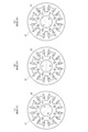
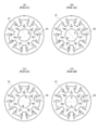
- FIG. 6 is a diagram for explaining a current flowing through each coil side of the DC motor according to the first embodiment of the present invention.
- the coil sides A, B, C, D, e, f, g, h, and i are, as shown in FIG.
- a current flows from the front to the back of the paper
- the coil sides E, F, G, H, I, a, b, c, and d flow from the back to the front of the paper. It should be noted that currents flow in opposite directions to the coil side e and the coil side I housed in the same slot.
- the coil sides i and D are housed in the direction along the boundary line of the magnetic pole NS of the rotor 20 shown in FIG. 6A (from the slot position where the coil sides e and I are housed).
- a magnetic field is generated in a direction toward an intermediate position between the slot and the slot accommodating the coil sides a and E).
- the magnetic field of the stator 10 and the magnetic field of the rotor 20 have a phase difference of approximately 90 °, and a force is applied to the rotor 20 so that the magnetic field direction of the rotor 20 is aligned with the magnetic field direction of the stator 10.
- counterclockwise torque acts on the rotor 20, and the rotor 20 rotates counterclockwise, which is the forward rotation direction in this embodiment.
- the N pole of the rotor 20 faces the sensors Sf, Sg, Sh, Si as shown in FIG. 6 (B).
- the S pole of the rotor 20 faces the sensors Sa, Sb, Sc, Sd, Se.
- the output values of the AND circuit of the fourth stage 54 connected to the gate of the transistor TA1 and the AND circuit of the fourth stage 54 connected to the gate of the transistor TF2 become "H", and the gates of the other transistors.
- the outputs of the AND circuits connected to all are "L”. Then, as illustrated at time t12 in FIG. 5, only the transistors TA1 and TF2 are turned on, and all other transistors are turned off.
- the current from the DC power supply 60 flows to the coil group of the path of the coil A, the coil B, the coil C, the coil D, and the coil E and the coil group of the path of the coil I, the coil H, the coil G, and the coil F. Since they flow separately, the coil sides A, B, C, D, E, f, g, h, and i are shown in FIG. A current flows through G, H, I, a, b, c, d, and e from the back of the paper toward the front. It should be noted that currents flow in opposite directions to the coil side a and the coil side E housed in the same slot. Therefore, inside the stator 10, a direction along the NS boundary line of the rotor 20 shown in FIG.
- a magnetic field is generated in a direction from an intermediate position between the coil sides a and E toward a slot position in which the coil sides a and E are housed. Due to this magnetic field, counterclockwise torque acts on the rotor 20, and the rotor 20 rotates counterclockwise.
- the current from the DC power supply 60 flows to the coil group of the path of the coil B, the coil C, the coil D, and the coil E and the coil group of the path of the coil A, the coil I, the coil H, the coil G, and the coil F. Since they flow separately, the coil sides B, C, D, E, f, g, h, i, and a are shown in FIG. An electric current flows through G, H, I, A, b, c, d, and e from the back of the paper toward the front. It should be noted that currents flow in opposite directions to the coil side f and the coil side A housed in the same slot.
- the coil sides a and E are housed inside the stator 10 in the direction along the NS boundary line of the rotor 20 shown in FIG. 6C (from the slot position where the coil sides f and A are housed).
- a magnetic field in the direction toward the intermediate position between the slot and the slot accommodating the coil sides b and F) is generated. Due to this magnetic field, counterclockwise torque acts on the rotor 20, and the rotor 20 rotates counterclockwise.
- the rotor 20 receives the counterclockwise torque and rotates counterclockwise, the signal outputs of the respective sensors Sa to Si of the position detection sensor 40 change.
- the transistors TA1 to TI1 on the positive power supply side and the transistors TA2 to TI2 on the negative power supply side shown in 1 are switched to the on-state transistors.
- the rotor 20 continues to rotate in the counterclockwise direction which is the forward rotation direction.
- the rotor 20 rotates by 2 ⁇ / 9, that is, 40 °, between the time t11 and the time t13.
- the current flowing through all the coils of the stator 10 gives the rotation torque of the rotor 20. Therefore, a DC motor having a high coil current utilization rate can be obtained.
- the transistors TA1 to TI1 on the positive power supply side are switched on and the transistors TA2 to TI2 on the negative power supply side are switched.
- the switching of the ON state of is performed alternately. That is, at time t12, TF2 is turned on in place of the transistor TE2 on the minus power supply side from the state at time t11, TB1 is turned on in place of the transistor TA1 on the plus power supply side at time t13, and is turned off at time t14.
- the coil sides E, F, G, H, I, a, b, c and d are directed from the front side to the back side of the drawing sheet by the currents flowing in the respective coil groups, and the coil sides A, B, C and D. , E, f, g, h, i, current flows from the back of the paper toward the front. It should be noted that currents flow in opposite directions to the coil side e and the coil side I housed in the same slot. That is, the current flowing through each coil side Ai is in the opposite direction to the current flowing through each coil side Ai shown in FIG. As a result, inside the stator 10, a direction along the boundary line of the magnetic pole NS of the rotor 20 shown in FIG.
- the current flowing through each coil causes the coil side of the coil facing the N pole of the rotor and the coil side of the coil facing the S pole.
- the switching elements are switched between conducting and non-conducting so that and are in different directions.
- the transistor TE2 As a method of switching the transistor TE2 from TF2 to the on state, when the transistor TF2 on the minus power supply side is turned on, the transistor TE2 is not turned off at the same time, but the transistor TF2 is turned on. The TE2 is kept on for a very short time, and then the transistor TE2 is turned off. Therefore, the coil E is short-circuited for a very short time. This is the same as the phenomenon that the coil is short-circuited when the brush contacts the commutator pieces adjacent to each other in the DC motor with a brush, and is more stable than when the transistor TE2 and the transistor TF2 are simultaneously opened and closed. The current flowing through the coil can be switched.
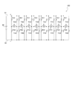
- FIG. 7 is an equivalent circuit excluding the position detection sensor and the control circuit of the DC motor according to the second embodiment of the present invention.
- the case where the number of coils of the stator winding is eight is shown.
- FIG. 8 is a diagram showing an example of the configuration of a control circuit for a DC motor according to the second embodiment
- FIG. 9 shows transitions between ON / OFF states of switching elements of the DC motor according to the second embodiment.
- FIG. 10 is a diagram for explaining a current flowing through each coil side of the DC motor according to the second embodiment of the present invention.
- the DC motor 102 of the present embodiment is one in which the coils A to H are connected in parallel via a transistor between a plus side power source line 61 and a minus side power source line 62.
- the structure of the stator is the same as that of the third embodiment described later, except that the method of connecting the coils A to H is different.
- the configuration of the rotor is the same as that of the first embodiment.
- the sensors Sa to Sh of the position detection sensor are the same as those of the first embodiment except that the numbers are different. In the present embodiment, eight sensors Sa to Sh are provided.
- one output line of the coil A is connected to the plus side power source line 61 and the minus side power source line 62, respectively, and a transistor TA1 forming a half bridge.
- Connect to the connection point of TA2 and connect the other lead wire of the coil A to the connection point of transistors TA3 and TA4 that form a half bridge connected to the positive power supply line 61 and the negative power supply line 62, respectively.
- the other coils B to H That is, the two leads of the coils A to H are connected to the connection points of the two switching elements forming a half bridge, and the coils A to H form a so-called full bridge or H bridge.
- each coil is not connected to another coil.
- the number of transistors, which are switching elements is required to be twice as large as that in the first embodiment.
- each coil AH is energized by four transistors.
- the pair of transistors TA1 and TA4 which are diagonal to the transistors TA1 to TA4 forming a so-called H bridge, are controlled to be turned on / off at the same time, or the transistors TA2 and TA3 are controlled.
- ON / OFF control is performed simultaneously for the group
- the other coils B to H and in FIG. 9, these groups are shown in two stages.
- t21 to t25 indicate time, and time elapses from top to bottom. Further, the transistors in the on state at each time are surrounded by a thick frame and are hatched.
- the control circuit 150 shown in FIG. 8 receives signals from the eight sensors Sa to Sh, and sends on / off signals to the gates of the 32 transistors TA1 to TH4, which are switching elements.
- the logic circuit forming the control circuit 150 has eight XOR circuits of the first stage 151 shown in FIG. Eight XOR circuits and eight NOT circuits in the stage 152, eight NOT circuits in the third stage 153, 16 AND circuits in the fourth stage 154, and 32 in the fifth stage 155. It is equipped with one amplifier.
- the signals from the two adjacent Hall elements, the sensors Sa and Sb are output from the first stage 151. It is input to the XOR circuit, and its output is input to the pair of AND circuits of the fourth stage 154 connected to the pair of transistors TA1 and TA2 forming one half bridge through the NOT circuit of the second stage 152. To be done. Further, the signal from the sensor Sa and the forward / reverse signal Q from the forward / reverse rotation control input terminal 70 are input to the XOR circuit of the second stage 152, and the output thereof is directly supplied to the transistor TA4 and the transistor TA1 via the amplifier.
- the N pole of the rotor 20 faces the sensors Sf, Sg, Sh, Sa, and the S pole of the rotor 20 functions as the sensors Sb, Sc, Sd, Se.
- case 2 When facing each other (hereinafter, this state is referred to as “case 2”), the outputs of the sensors Sf, Sg, Sh, Sa are “H”, and the outputs of the sensors Sb, Sc, Sd, Se are “L”. "It becomes.
- the transistors TB1, TB4, TC1, TC4, TD1 and TD4 are shown at time t21 in FIG.
- the current flowing through each coil side of the DC motor is as shown in the diagram at time t21 in FIG. 10 (A), and the coil sides B, C, D, f, g, and h are on the paper surface.
- the coil sides a and E are housed in the direction along the boundary line of the magnetic pole NS of the rotor 20 shown in FIG.
- a magnetic field (in the direction toward the slot) is generated. Due to this magnetic field, counterclockwise torque acts on the rotor 20, and the rotor 20 rotates in the counterclockwise direction, which is the forward rotation direction in this embodiment.
- the current flowing in each coil side of the DC motor is applied to the coil sides C, D, E, g, h, and a from the front side to the back side of the drawing and the coil sides.
- a current flows through the sides G, H, A, c, d, and e from the back of the paper toward the front.
- the coil sides b and F are housed in the direction along the boundary line between the magnetic poles NS of the rotor 20 shown in FIG.
- a magnetic field (in the direction toward the slot) is generated. Due to this magnetic field, counterclockwise torque acts on the rotor 20, and the rotor 20 rotates in the counterclockwise direction, which is the forward rotation direction in this embodiment.
- the N pole of the rotor 20 faces the sensors Sh, Sa, Sb, Sc, and the S of the rotor 20 moves.
- the pole faces the sensors Sd, Se, Sf, Sg.
- the transistor surrounded by a thick frame and hatched is turned on.
- the transistors TC1 to TC4 and the transistors TG1 to TG4 are turned off, no current flows through the coils C and G.
- the current flowing in each coil side of the DC motor is applied to the coil sides D, E, F, h, a, and b from the front side to the back side of the drawing and the coil sides.
- a current flows through the sides H, A, B, d, e, f from the back of the paper toward the front.
- the coil sides c and G are housed in the direction along the boundary line of the magnetic pole NS of the rotor 20 shown in FIG. 10B (from the slots storing the coil sides g and C to the coil sides c and G).
- a magnetic field (in the direction toward the slot) is generated.
- the current flowing through each coil side of the DC motor is opposite to the direction of the current shown in the diagram at time t21 in FIG. 10 (A). That is, the coil sides B, C, D, f, g, and h face the current from the back to the front of the paper, and the coil sides F, G, H, b, c, and d face the current from the front to the back of the paper.
- the coil sides e and A are housed in the direction along the boundary line of the magnetic pole NS of the rotor 20 shown in FIG. 10A (from the slots storing the coil sides a and E to the coil sides e and A).
- a magnetic field (in the direction toward the slot) is generated.
- the magnetic flux density due to the field of the rotor 20 is almost zero at the boundary of the magnetic pole NS of the rotor 20.
- the back electromotive force is not generated in the coils A and E housed in the slots located at this boundary. Therefore, when the coils A and E are connected to the DC power supply 60, an overcurrent may flow. Therefore, in the second embodiment, for the coil housed in the slot facing the position where the polarity of the rotor 20 is switched, at least one half-bridge transistor connected to the lead wire of this coil is not connected. By making it conductive, a blanking period in which no current from the DC power supply 60 flows is provided.
- a coil in a blanking period in which no current flows is called a blanking coil.
- the blanking coil is two coils located near the boundary of the magnetic pole NS.
- the influence of the blanking coil is reduced and the current utilization efficiency of the coil is increased by increasing the number of slots and the number of coils of the stator 10. The same applies to other embodiments that generate a blanking coil.
- each coil is connected in parallel to the DC power supply 60, whereas in the first embodiment, each coil is connected in series to the DC power supply 60.
- the plurality of coils are connected in series so as to form a closed loop, and the plurality of coils are divided into two coil groups so that a current flows through each of the two coil groups.
- the number of transistors in the ON state is one of the transistors TA1 to TI1 connected to the positive power supply line 61 and one of the transistors TA2 to TI2 connected to the negative power supply line 62. Is.
- each transistor TA1 to TI2 requires a current capacity of 2 L ampere.
- each transistor TA1 to TI2 should be a transistor having a large withstand voltage. Must be used. This tendency becomes remarkable when the number of slots of the stator 10 is increased and the number of coils is increased in order to smooth the rotation of the DC motor.
- each of the transistors TA1 to TI4 needs only to have a capacity capable of flowing a predetermined current value L amperes, and therefore has a current capacity higher than that of the DC motor according to the first embodiment. Small transistors can be used. Further, in the DC motor according to the second embodiment, the power supply voltage of the DC power supply 60 can be reduced and the withstand voltage of the transistor can be used as compared with the DC motors according to the first and second embodiments.
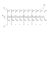
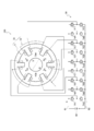
- FIG. 11 is a diagram showing a configuration example excluding a DC motor control circuit according to a third embodiment of the present invention
- FIG. 12 is a DC motor position detection sensor and control circuit according to the third embodiment. Is an equivalent circuit except.
- the stator 10 of the DC motor 103 according to the present embodiment includes a stator core 11 formed by laminating silicon steel plates having n (n is an integer of 4 m or more, and in the present embodiment 8) slots and a two-layer winding. Is provided with a stator winding 12 made up of eight coils A to H housed in each slot of the stator core. This structure is the same as that of the second embodiment except that the number of coils is different.
- each coil A to H is a two-pole machine and has an even number of slots, the two coil sides of each coil are housed in slots at positions separated by 180 °. Therefore, in the present embodiment, the coil pitch is equal to the magnetic pole pitch.
- the configurations of the rotor 20 and the sensors Sa to Sh are the same as those in the second embodiment.
- the coils A to H are connected in series, but when an electric current is applied to two adjacent coils, a magnetic field in the opposite direction is generated in a region surrounded by the two coils in common.
- the lead wires of two adjacent coils are sequentially connected and connected in series in a ring shape.
- Each connection point of the output line is connected to a connection point of two switching elements that form a half bridge connected to the positive power supply line and the negative power supply line of the DC power supply.
- the output line on the coil side H side of the coil H is connected to the output line on the coil side A of the adjacent coil A, and the connection point is connected to the positive side power supply line 61 via the transistor TA1. At the same time, it is connected to the negative power supply line 62 via the transistor TA2. Further, a lead wire on the coil side a of the coil A and a lead wire on the coil side b of the coil B adjacent to the coil A are connected, and the connection point is connected to the positive power supply line 61 via the transistor TB1. , And is connected to the minus power supply line 62 via the transistor TB2.
- the output line on the coil side B side of the coil B and the output line on the coil side C side of the adjacent coil C are connected, and the connection point is connected to the positive side power supply line 61 via the transistor TC1.
- the same is applied in sequence, and the output line on the coil side g side of the coil G and the output line on the coil side h side of the coil H are connected, and the connection point is connected to the positive side power supply line 61 via the transistor TH1.
- it is connected to the minus side power supply line 62 via the transistor TH2.
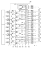
- FIG. 13 is a diagram showing a configuration example of a DC motor control circuit according to a third embodiment of the present invention
- FIG. 14 is an ON / OFF state of a switching element of the DC motor according to the third embodiment. It is a figure which shows the transition of.
- FIG. 15 is a diagram for explaining a current flowing through each coil side of the DC motor according to the third embodiment.
- the control circuit 250 shown in FIG. 13 receives the signals from the eight sensors Sa to Sh and sends an on / off signal to the gates of the 16 transistors TA1 to TH2 that are switching elements.
- the logic circuit forming the control circuit 250 has eight XOR circuits of the first stage 251 and the second stage 252. Eight XOR circuits, four NOT circuits in the third stage 253, twelve NOT circuits in the fourth stage 254, 16 AND circuits in the fifth stage 255, and six NOT circuits in the sixth stage 256. It has 16 amplifiers.
- two adjacent Hall sensors Sa The signals from Sb and Sb are input to the XOR circuit of the first stage 251 and the output thereof becomes the pair of the fifth stage 255 connected to the transistors TD1 and TD2 via the NOT circuit of the fourth stage 254. It is input to each AND circuit. Further, the signal from one sensor Sa and the forward / reverse signal Q from the forward / reverse rotation control input terminal 70 are input to the XOR circuit of the second stage 252, and the output thereof is the AND of the fifth stage 255 forming a pair.
- the N pole of the rotor 20 faces the sensors Sa, Sb, Sc, Sd, and the S pole of the rotor 20 serves as the sensors Se, Sf, Sg, Sh. Assuming that they are facing each other (hereinafter, this state is referred to as “Case 3”), the outputs of the sensors Sa, Sb, Sc, Sd are “H”, and the outputs of the sensors Se, Sf, Sg, Sh are “L”. "It becomes.
- the current from the DC power supply 60 to each of the coils A to H passes through the transistor TB1 on the plus power supply side, the coil A, and the transistor TA2 on the minus power supply side, the transistor TB1 on the plus power supply side, the coil B, the coil C, the minus.
- a current, a current passing through the transistor TH1 on the plus power source side, the coil G, the coil F, and the transistor TF2 on the minus power source side, and a current passing through the transistor TH1 on the plus power source side, the coil H, and the transistor TA2 on the minus power source side flow.
- the coil sides C, D, E, F, g, h, a, and b are from the front side of the drawing due to the current flowing in each coil, as shown in FIG. 15 (A).
- An electric current flows toward the back, and the current rises from the back to the front on the coil sides G, H, A, B, c, d, e, and f.
- the direction along the boundary line of the magnetic pole NS of the rotor 20 shown in FIG. 15 (A) (the slots accommodating the coil sides f and B and the coil sides g and C are accommodated.
- a magnetic field is generated from a position intermediate the slot to a position intermediate between the slot containing the coil sides b and F and the slot containing the coil sides c and G). Due to this magnetic field, counterclockwise torque acts on the rotor 20, and the rotor 20 rotates in the counterclockwise direction which is the forward rotation direction in this embodiment.
- the two coils of the coils B and C and the two coils of the coils F and G are connected to the DC power supply 60 in series, and thus are connected individually to the DC power supply 60.
- the value of the current flowing is smaller than that of the other coils A, D, E and H.
- the N pole of the rotor 20 faces the sensors Sb, Sc, Sd, Se as shown at time t32 in FIG. 15 (B).
- the S pole of the rotor 20 faces the sensors Sf, Sg, Sh, Sa.
- the output value of the AND circuit of the fifth stage 255 connected to the gates of the transistors TA2, TB1, TC2, TE1, TF2, and TG1 becomes "H", and the AND circuit connected to the gates of the other transistors.
- the on / off state of each transistor in this state is as shown at time t32 in FIG.
- the state at time t32 is such that the upper transistor TG1 and the lower transistor TC2 are switched from the off state to the on state, and the upper transistor TH1 and the lower transistor TD2 are switched from the on state to the off state. There is.
- the current from the DC power source 60 to each of the coils A to H passes through the transistor TB1 on the positive power source side, the coil A, the transistor TA2 on the negative power source side, the transistor TB1 on the positive power source side, the coil B, and the negative power source side.
- a magnetic field is generated from a position intermediate the slot to a position intermediate between the slot containing the coil sides c and G and the slot containing the coil sides d and H). Due to this magnetic field, counterclockwise torque acts on the rotor 20, and the rotor 20 rotates in the counterclockwise direction which is the forward rotation direction in this embodiment.
- the two coils of the coils B and C and the two coils of the coils F and G are connected to the DC power supply 60 in series, and thus are independently connected to the DC power supply 60.
- the value of the current flowing is smaller than that of the other coils A, D, E and H.
- the N pole of the rotor 20 faces the sensors Sc, Sd, Se, Sf, and the S pole of the rotor 20 detects the sensor, as shown in FIG. It faces Sg, Sh, Sa, Sb.
- the transistors TA1 to TH2 as shown at time t33 in FIG. 14, from the state at time t32, the upper transistor TD1 and the lower transistor TH2 are switched from the off state to the on state, and the upper transistor TE1 and the lower transistor The transistor TA2 of is switched from the on state to the off state.
- a current flows from the DC power supply 60 to the coil sides A to h of the coils A to H at time t33 in FIG. 15C, and the direction along the boundary line of the magnetic pole NS of the rotor 20 (coil (A direction from an intermediate position between a slot accommodating sides h and D and a slot accommodating coil sides a and E toward an intermediate position between a slot accommodating coil sides d and H and a slot accommodating coil sides e and A) Magnetic field is generated. Due to this magnetic field, counterclockwise torque acts on the rotor 20, and the rotor 20 continues to rotate in the counterclockwise direction which is the forward rotation direction in this embodiment.
- the rotor 20 rotates twice twice 2 ⁇ / 8, that is, 90 °.
- the forward / reverse signal Q from the forward / reverse rotation control input terminal 70 has the reverse rotation logical value “L” in the case 3 shown in FIG. 13 or FIG.
- the rotor 20 continues to rotate clockwise, which is the reverse rotation direction.
- each coil is connected directly to the DC power supply 60 via the two transistors, and There are two types of connection forms to the DC power supply 60 when directly connected to the DC power supply 60 via two transistors in the state of being connected in series. Therefore, it is possible to use a transistor having a smaller current capacity and withstand voltage than those of the first embodiment.
- the coil housed in the slot located on the boundary line of the magnetic pole NS of the rotor 20 has no blanking period, but the coil housed in the slot located on the boundary line of the magnetic pole NS of the rotor 20. Since the two adjacent coils are connected in series and connected to the DC power supply 60, the influence of overcurrent due to the reduction of the back electromotive force can be suppressed to be small.
- FIG. 16 is an equivalent circuit excluding the position detection sensor and the control circuit of the DC motor according to the fourth embodiment.
- the stator of the DC motor 104 according to the present embodiment includes a stator core formed by laminating silicon steel plates having n (n is an integer of 4 m or more, and 9 in the present embodiment) slots, and a stator core. It has a stator winding consisting of nine coils A to I housed in slots.
- the configurations of the stator core and the stator windings and the configurations of the sensors Sa to Si are the same as those of the first embodiment shown in FIG. 1 except for the connection method of the coils A to I.
- the number of half bridges is one more than in the DC motor 101 of the first embodiment.
- the coils A to I are connected in series, but are connected in the reverse direction. That is, when an electric current is applied to two adjacent coils, the lead wires of the two adjacent coils are sequentially connected so that a magnetic field in the opposite direction is generated in a region commonly surrounded by the two coils. Connected in series.
- the number of coils is an odd number, they are not connected in a ring shape but are simply connected in series.
- the coil A and the coil I are not connected.
- the coil pitch is a short pitch winding shorter than the magnetic pole pitch.
- the other connection form of the coil is the same as that of the third embodiment, and the description thereof will be omitted.
- connection point of the lead wire is connected to the connection point of two switching elements that form a half bridge connected to the positive and negative power lines of the DC power supply, respectively. Therefore, 20 transistors TA1 to TJ2 are connected to the nine coils A to I.
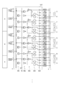
- FIG. 17 is a diagram showing a configuration example of a DC motor control circuit according to a fourth embodiment of the present invention
- FIG. 18 is an ON / OFF state of a switching element of the DC motor according to the fourth embodiment. It is a figure which shows the transition of.
- FIG. 19 is a diagram for explaining a current flowing through each coil side of the DC motor according to the third embodiment.
- the control circuit 350 shown in FIG. 17 receives signals from the nine sensors Sa to Si and sends on / off signals to the gates of the 20 transistors TA1 to TJ2 that are switching elements.
- the logic circuit configuring the control circuit 350 has nine XOR circuits of the first stage 351 shown in FIG.
- 18 amplifiers and a sub logic circuit 357 receives signals from the nine sensors Sa to Si and sends on / off signals to the gates of the 20 transistors TA1 to TJ2 that are switching elements.
- the logic circuit configuring the control circuit 350 has nine XOR circuits of the first stage 351 shown in FIG.
- control circuit 350 of the fourth embodiment shown in FIG. 17 shows that the coil H
- a sub-logic circuit 357 is added for the half bridge composed of the transistors TI1 and TI2 and the half bridge composed of the transistors TJ1 and TJ2.
- a gate signal is generated from the sub logic circuit 357 which receives the signal.
- the transistors TA1 and TA2 are half bridges connected to the coil A on one end side of the coils connected in series, and the transistors TJ1 and TJ2 are half bridges connected to the coil on one end side of the coil I connected in series.
- the outputs of the AND circuits forming the pair of the fifth stage 355 connected to the transistors TA1 and TA2 are input to the XOR circuits via the NOT circuits, respectively, and the outputs of the XOR circuits and the respective NOT circuits are input. Is input to a paired AND circuit connected to the transistors TJ1 and TJ2.
- the N pole of the rotor 20 faces the sensors Sa, Sb, Sc, Sd, Se, and the S pole of the rotor 20 is the sensors Sf, Sg, Sh, Assuming the state of facing the Si (hereinafter, this case is referred to as “Case 4”), the outputs of the sensors Sa, Sb, Sc, Sd, Se are “H”, and the sensors Sf, Sg, Sh, Si have the outputs. The output becomes "L".
- the coil housed in the slot located at the boundary line of the magnetic pole NS of the rotor 20 has two adjacent coils connected in series and connected to the DC power supply 60. It is possible to suppress the influence of an overcurrent flowing due to the reduction in power.
- the N pole of the rotor 20 faces the sensors Sb, Sc, Sd, Se as shown at time t42 in FIG. 19B.
- the S pole of the rotor 20 faces the sensors Sf, Sg, Sh, Si, Sa.
- the currents flowing through the coil groups cause currents to flow toward the coil sides B, C, D, e, f, g, and h from the front to the back of the drawing, as shown in FIG.
- the coil sides i and D are housed in the direction along the boundary line between the magnetic poles NS of the rotor 20 shown in FIG. 19B (from the slots storing the coil sides e and I to the coil sides i and D).
- a magnetic field is generated in a direction toward an intermediate position between the slot and the slot accommodating the coil sides a and E).
- each coil is connected directly to the DC power supply 60 via two transistors, and when two coils are connected in series, two coils are connected.
- the DC power supply 60 there are two types of connection forms to the DC power supply 60, and further, a blanking period in which no current flows in the coils at both ends connected in series occurs. Therefore, it is possible to use a transistor having a smaller current capacity and withstand voltage than those of the first embodiment.
- the stator 10 of the DC motor 105 includes a stator core 11 formed by laminating silicon steel plates having n (n is an integer of 4 m or more, and in the present embodiment 6) slots and a two-layer winding.
- the stator winding 12 includes six coils A to F housed in each slot of the stator core. Further, the DC motor 105 has six Sa to Sf.
- the number of coils is an even number
- two adjacent coils are divided into a series of coil pairs, and the two coils of each coil pair are connected in the reverse direction. That is, when a current is applied from one of the two coils forming the coil pair to the other, a magnetic field in the opposite direction is generated in a region which is commonly surrounded by the two coils.
- the lead wire of is connected. Then, the connection points of the output lines of the two coils of each coil pair and the output lines at both ends are connected to the connection points of the two transistors forming each half bridge.
- each coil pair is formed such that when a current is passed from one of the coil pairs connected in series to the other, a magnetic field in the opposite direction is generated in the region commonly surrounded by these two coil pairs.
- Connect the leads of the two coils The connection points of the two coils of each coil pair and the output lines at both ends are connected to the connection points of the two transistors forming the half bridge. Therefore, six transistors that form three half bridges are connected to each coil pair.
- the lead wire on the coil side a of the coil A shown in FIG. 20 is connected to the lead wire of the coil side b of the adjacent coil B, and the connection is made.
- the point is connected to the positive side power supply line 61 via the transistor Tab1 and is connected to the negative side power supply line 62 via the transistor Tab2.
- the lead wire on the coil side A side of the coil A is connected to the positive power supply line 61 via the transistor TA1 and is connected to the negative power supply line 62 via the transistor TA2.
- the lead wire on the coil side B side of the coil B is connected to the positive power supply line 61 via the transistor TB1 and to the negative power supply line 62 via the transistor TB2.
- the coil pair including the coils C and D and the coil pair including the coils E and F As described above, in the present embodiment, two coils and six transistors connected in series form one set.
- FIG. 22 is a diagram showing a configuration example of a DC motor control circuit according to the fifth embodiment of the present invention
- FIG. 23 is an ON / OFF state of a switching element of the DC motor according to the fifth embodiment. It is a figure which shows the transition of.
- FIG. 24 is a diagram for explaining a current flowing through each coil side of the DC motor according to the fifth embodiment.
- the control circuit 450 shown in FIG. 22 receives signals from the six sensors Sa to Sf, and sends on / off signals to the gates of the eighteen transistors TA1 to TF2 that are switching elements.
- the logic circuit configuring the control circuit 450 includes six XOR circuits of the first stage 451 shown in FIG. Six NOT circuits in the third stage 452 and three XOR circuits, six NOT circuits in the third stage 453, twelve AND circuits in the fourth stage 454, three NOT circuits, and the fifth stage It has 18 amplifiers of 455.
- the signals from the two adjacent Hall elements, the sensors Sf and Sa are the first stage 451. Is input to the AND circuit of the fourth stage 454 connected to the transistors TA1 and TA2, respectively, through the NOT circuit of the second stage 452. Further, the signal from one sensor Sa and the forward / reverse signal Q from the forward / reverse rotation control input terminal 70 are input to the XOR circuit of the second stage 452, and the output thereof is the AND of the fourth stage 454 forming a pair. It is directly input to one of the circuits and input to the other AND circuit via the NOT circuit of the third stage 453. Therefore, the output values of the AND circuits forming a pair in the fourth stage 454 connected to the transistors TA1 and TA2 do not simultaneously become “H”.
- the sensor is added to the XOR circuit of the second stage 452 in the sensor.
- the signal from Sa and the forward / reverse signal Q from the forward / reverse rotation control input terminal 70 are input, and the output is input to one transistor Tab1 and the other transistor Tab2 is input to the NOT circuit of the fourth stage 454. Be entered via. Therefore, the output values of the AND circuits forming a pair in the fourth stage 454 connected to the transistors Tab1 and Tab2 do not become "H" at the same time.
- the XOR circuit of the first stage 451 has two sensor elements Sa that are adjacent Hall elements Sa. And the signals from Sb are input, and the outputs thereof are input to the AND circuits forming a pair of the fourth stage 454 connected to the transistors TB1 and TB2 via the NOT circuits of the second stage 452. Further, the signal from one sensor Sa and the forward / reverse signal Q from the forward / reverse rotation control input terminal 70 are input to the XOR circuit of the second stage 452, and the output thereof is the fourth stage 454 forming a pair.
- the N pole of the rotor 20 faces the sensors Sb, Sc, Sd, and the S pole of the rotor 20 faces the sensors Se, Sf, Sa.
- case 5 the state (hereinafter, referred to as “case 5”) is present, the outputs of the sensors Sb, Sc, Sd are “H”, and the outputs of the sensors Se, Sf, Sa are “L”.
- the forward / reverse signal Q from the forward / reverse rotation control input terminal 70 has the logic value "H" of the forward rotation, the transistors Tab1, TC1, TD1, Tef1 are indicated by a frame and hatching at time t51 in FIG.
- the coil B connected to the half bridge composed of the transistors TB1 and TB2 and the coil E connected to the half bridge composed of the transistors TE1 and TE2 are blanking coils through which no current flows.
- the current passing through the transistor Tab1 on the positive power supply side, the coil A, the transistor TA2 on the negative power supply side, the transistor TC1 on the positive power supply side, the coil C, and the negative power supply side A current passing through the transistor Tcd2, a current passing through the transistor TD1 on the plus power source side, the coil D, the transistor Tcd2 on the minus power source side, a current passing through the transistor Tef1 on the plus power source side, the coil F, and the transistor TF2 on the minus power source side flows. .
- the transistors TA1 to TF2 change from the state at time t51 to the transistor TE1 in the upper stage and the transistors TB2 and Tef2 in the lower stage from the off state to the on state, and the transistor TC1 in the upper stage.
- the Tef1 and the lower transistor TF2 are switched from the on state to the off state.
- the current passing through the transistor Tab1 on the positive power supply side, the coil A, the transistor TA2 on the negative power supply side, the transistor Tab1 on the positive power supply side, the coil B, and the negative power supply side A current passing through the transistor TB2, a current passing through the transistor TD1 on the positive power source side, the coil D, the transistor Tcd2 on the negative power source side, a current passing through the transistor TE1, a coil E on the positive power source side, and the transistor Tef2 on the negative power source side flows. . Further, no current flows through the coils C and F.
- a current shown at time t52 in FIG. 24 (B) flows from the DC power supply 60 to the coil sides A to h of the coils A to H, and the direction along the boundary line of the magnetic pole NS of the rotor 20 (
- a magnetic field is generated from the slot position in which the coil sides f and C are stored to the slot position in which the coil sides c and F are stored. Due to this magnetic field, counterclockwise torque acts on the rotor 20, and the rotor 20 continues to rotate in the counterclockwise direction which is the forward rotation direction in this embodiment. Note that the rotor 20 rotates by 2 ⁇ / 6, that is, 60 °, between the time t51 and the time t52.
- the two coils housed in the slots located on the boundary line of the magnetic pole NS of the rotor 20 are not connected to the DC power supply 60 as blanking coils, so that the counter electromotive force becomes small and the overcurrent is reduced. Can suppress the effect of flowing.
- one of the two transistors connected to the connection point of the coil sides of the two coils forming the coil pair is in the ON state, when the current flows through each coil, the port of one coil side must be connected.
- the output line and the output line on the other coil side are connected to the DC power supply via the transistor. Therefore, in this embodiment, similarly to the second embodiment, it is possible to use a transistor having a smaller current capacity and withstand voltage than those of the first embodiment. Further, by increasing the number of slots and the number of coils of the stator 10, it is possible to reduce the influence of the blanking coil and improve the current utilization efficiency of the coil.
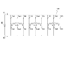
- FIG. 25 is an equivalent circuit excluding the position detection sensor and the control circuit of the DC motor according to the sixth embodiment.
- the stator 10 of the DC motor 106 of the present embodiment is formed by laminating silicon steel plates having n (n is an integer of 4 m or more, and 7 in the present embodiment) slots.
- n is an integer of 4 m or more, and 7 in the present embodiment
- a stator core and a stator winding including seven coils A to G housed in each slot of the two-layer wound stator core are provided.
- the DC motor 106 has seven sensors Sa to Sg.
- each coil A to G is a two-pole machine and has an odd number of slots, the two coil sides of each coil are accommodated in slots at positions shorter than 180 °. Therefore, in the present embodiment, the coil pitch is short pitch winding shorter than the magnetic pole pitch.
- the number of coils is an odd number
- two adjacent coils are divided into a coil pair in which they are connected in series and one independent coil
- the two coils of each coil pair are connected in the reverse direction. That is, when a current is applied from one of the two coils forming the coil pair to the other, a magnetic field in the opposite direction is generated in a region which is commonly surrounded by the two coils.
- the lead wire of is connected.
- the connection points of the output lines of the two coils of the coil pair and the output lines of both ends are connected to the connection points of the two transistors forming the half bridge, respectively, and the output lines of both ends of the single coil are connected.
- the sixth embodiment since the sixth embodiment has an odd number of coils, it has a configuration in which a single coil and a switching element for this single coil are added to the fifth embodiment. Therefore, as is clear from the equivalent circuit according to the fifth embodiment shown in FIG. 21 and the equivalent circuit according to the sixth embodiment shown in FIG. 25, the six coils A to F with respect to the DC power supply 60 and the transistors.
- the connection form of 18 transistors from TA1 to TF2 is the same as that of the fifth and sixth embodiments.
- the coil G which is a single coil, is the same as in the second embodiment, and is connected to four transistors TG1 to TG4 forming a so-called H bridge or full bridge.
- FIG. 26 is a figure which shows one structural example of the control circuit of the direct-current motor which concerns on the 5th Embodiment of this invention
- FIG. 27 ON / OFF state of the switching element of the direct-current motor which concerns on a 6th Embodiment. It is a figure which shows the transition of.
- FIG. 28 is a diagram for explaining a current flowing through each coil side of the DC motor according to the sixth embodiment.
- the control circuit 550 shown in FIG. 26 receives signals from the seven sensors Sa to Sg and sends on / off signals to the gates of the 22 transistors TA1 to TG4, which are switching elements.
- the logic circuit that constitutes the control circuit 550 of the present embodiment will be described in comparison with the control circuit 450 of the DC motor 105 according to the fifth embodiment shown in FIG. 22, which will be described as a pair connected to the transistors TA1 and TA2.
- the output of the sensor input to the AND circuit is the sensors Sg and Sa, and signals are received from the sensors Sf and Sg to turn on / off the transistors TG1 to TG4 connected to the coil G. Except that a logic circuit for outputting is added, the logic circuits that generate signals for turning on / off the 18 transistors TA1 to TF2 connected to the coils A to F are logically the same, The description is omitted.
- the independent coil G is the same as the logic circuit that generates signals for turning on / off the four transistors connected to each coil of the DC motor 102 according to the second embodiment, and therefore the description thereof will be given. Omit it.
- the N pole of the rotor 20 faces the sensors Sb, Sc, Sd, and the S pole of the rotor 20 faces the sensors Se, Sf, Sg, Sa. Assuming that the sensor Sb, Sc, Sd outputs “H” and the sensors Se, Sf, Sg, Sa output “L”. .
- the transistors Tab1, TC1, TD1, as shown by the thick frame and hatching at time t61 in FIG. Tef1, TG3, TA2, Tcd2, TF2 and TG2 are turned on, and all other transistors are turned off.
- the coil B connected to the half bridge composed of the transistors TB1 and TB2 and the coil E connected to the half bridge composed of the transistors TE1 and TE2 are blanking coils through which no current flows.
- the current from the DC power source 60 to the coils A to G passes through the transistor Tab1 on the positive power source side, the coil A, the transistor TA2 on the negative power source side, the transistor TC1 on the positive power source side, the coil C, and the negative power source side.
- a magnetic field is generated in the direction from the middle position of the slot to the slot position where the coil sides b and E are housed. Due to this magnetic field, counterclockwise torque acts on the rotor 20, and the rotor 20 rotates in the counterclockwise direction which is the forward rotation direction in this embodiment.
- the N pole of the rotor 20 faces the sensors Sb, Sc, Sd, Se, and the S pole of the rotor 20 detects the sensor Sf, It faces Sg and Sa.
- the rotor 20 is moved clockwise from the state at time t61 to the state at time t62 by an angle of 2 ⁇ / (7 ⁇ 2).
- the transistors TA1 to TG4 change from the state at time t61 to the transistor TE1 in the upper stage and the transistor Tef2 in the lower stage from the off state to the on state at time t62.
- the transistor Tef1 and the lower transistor TF2 are switched from the on state to the off state.
- a current flows from the direct-current power supply 60 to the coils A to G through the transistor TE1 on the plus power supply side, the coil E, and the transistor Tef2 on the minus power supply side, and at the same time to the coil F. Does not flow current. Therefore, a current flows from the DC power supply 60 to the coil sides Ag of the coils A to H at time t62 in FIG. 28B, and the magnetic field in the direction along the boundary line of the magnetic pole NS of the rotor 20 is generated. Occurs. Due to this magnetic field, counterclockwise torque acts on the rotor 20, and the rotor 20 continues to rotate in the counterclockwise direction which is the forward rotation direction in this embodiment.
- the two coils housed in the slots located at the boundaries of the magnetic poles NS of the rotor 20 are not connected to the DC power supply 60 as blanking coils, so that a counter electromotive force is generated. It is possible to suppress the influence of overcurrent due to the reduction in power. Further, since one of the two transistors connected to the connection point of the coil sides of the two coils forming the coil pair is in the ON state, when the current flows through each coil, the port of one coil side must be connected. The output line and the output line on the other coil side are connected to the DC power supply via the transistor. Therefore, it is possible to use a transistor having a smaller current capacity and withstand voltage than those of the first embodiment. Further, by increasing the number of slots and the number of coils of the stator 10, it is possible to reduce the influence of the blanking coil and improve the current utilization efficiency of the coil.
- the rotor of the DC motor according to the present invention may be a permanent magnet rotor or may include an exciting coil.
- the DC motor according to the seventh embodiment includes an exciting coil as a rotor.
- the direct current supplied to the exciting coil may be supplied to the rotor side through a slip ring, and coaxial coils are provided on the rotor side and the stator side to feed the exciting coil without contact.
- the AC voltage induced on the rotor side using electromagnetic induction may be rectified by the diode bridge to drive the exciting winding on the rotor side by DC.
- the DC motor having a two-pole rotor may have four or more coils, and in the case of a DC motor having a forward connection coil, cogging is reduced. Therefore, it is desirable that the number of slots in the stator be odd. Therefore, it is more desirable that the number of coils is an odd number of 5 or more. Further, in each of the embodiments, an example in which the number of coils is small is described to simplify the description, but it is preferable that the number of coils is 18 or more, for example.
- the number of magnetic poles of the rotor is 2
- the number of magnetic poles of the rotor may be 2 m (m is an integer).
- the number of slots of the stator may be an integer of 4 m or more.
- n coils may be housed in slots separated by n / 2m (however) slots.
- the conduction / non-conduction of the switching element is switched so that the current flowing through the coil is directed in a different direction between the coil side of the coil facing the N pole of the rotor and the coil side of the coil facing the S pole. You can do it like this.
- two adjacent coils are divided into a pair of coils connected in series.
- three adjacent coils or three or more coils are connected in series. It is also possible to configure a connected coil group and provide a half bridge at the connection point of each lead wire of this coil group.
- the inner rotor type DC motor having the stator arranged around the rotor has been described as an example, but it is configured as an outer rotor type motor having the rotor arranged around the stator or an axial gap type motor. You may. Further, it can be configured as a slotless motor or a coreless motor.
- control circuit is composed of a logic circuit
- a microcomputer may be used.
- a table of gate signals for turning on / off each transistor for the position of the rotor 20 is stored in advance in the memory of the microcomputer, and the position signal of the rotor 20 from the sensor is input to the microcomputer.
- the gate signal to each transistor can be configured to be output from the microcomputer.
- a rotary encoder or a resolver may be used instead of the Hall element to detect the position of the rotor.
- a DC motor has been described above as an example of the DC machine of the present invention, but the DC motor described in each embodiment can function as a generator as well as a conventional brushed DC motor depending on driving conditions.
- the DC motor described in each embodiment can function as a generator as well as a conventional brushed DC motor depending on driving conditions.
- the kinetic energy of the rotor is converted to electrical energy and returned to the DC power source side, and further, the DC power source itself is charged as a load, or the DC power source Can be replaced by a load.
- Making the DC machine of the present invention function as a generator and replacing the DC power supply with another load is within the technical scope of the matters described in the claims.
Landscapes
- Engineering & Computer Science (AREA)
- Power Engineering (AREA)
- Microelectronics & Electronic Packaging (AREA)
- Control Of Motors That Do Not Use Commutators (AREA)
- Brushless Motors (AREA)
- Inverter Devices (AREA)
Abstract
L'invention concerne une machine à courant continu permettant d'obtenir un taux d'utilisation de courant élevé, en configurant une machine à courant continu comportant une pluralité de lames de collecteur de façon à être sans collecteur ou sans balai. Une machine à courant continu (101) est équipée : d'un rotor qui comprend des pôles magnétiques constitués de 2m pôles N et de 2m pôles S (m étant un nombre entier) ; et d'un stator qui comprend n bobines présentant un pas de bobinage approximativement égal au pas polaire magnétique du rotor et dont les phases sont déviées de 2π/n (n étant un nombre entier égal ou supérieur à 4m). Chaque bobine comporte deux fils conducteurs, et chaque fil conducteur est connecté à un point de connexion de deux éléments de commutation d'un demi-pont, qui est constitué par les deux éléments de commutation connectés à une source d'alimentation en courant continu (60). Un circuit de commande (50) commute les éléments de commutation entre un état conducteur et un état non conducteur de telle sorte que, en fonction des positions des pôles magnétiques du rotor (20), le courant circule vers les bobines dans différentes directions entre un côté bobine d'une bobine opposée au pôle N du rotor et un côté bobine d'une bobine opposée au pôle S du rotor.
Applications Claiming Priority (2)
| Application Number | Priority Date | Filing Date | Title |
|---|---|---|---|
| JP2018202125A JP6610910B1 (ja) | 2018-10-26 | 2018-10-26 | 直流機 |
| JP2018-202125 | 2018-10-26 |
Publications (1)
| Publication Number | Publication Date |
|---|---|
| WO2020085507A1 true WO2020085507A1 (fr) | 2020-04-30 |
Family
ID=68691986
Family Applications (1)
| Application Number | Title | Priority Date | Filing Date |
|---|---|---|---|
| PCT/JP2019/042022 Ceased WO2020085507A1 (fr) | 2018-10-26 | 2019-10-25 | Machine à courant continu |
Country Status (2)
| Country | Link |
|---|---|
| JP (1) | JP6610910B1 (fr) |
| WO (1) | WO2020085507A1 (fr) |
Cited By (1)
| Publication number | Priority date | Publication date | Assignee | Title |
|---|---|---|---|---|
| EP4187772A1 (fr) * | 2021-11-29 | 2023-05-31 | Hilti Aktiengesellschaft | Machine-outil dotée d'un moteur sans brosse et procédé de commande d'une machine-outil |
Families Citing this family (1)
| Publication number | Priority date | Publication date | Assignee | Title |
|---|---|---|---|---|
| JP7486712B2 (ja) | 2020-04-27 | 2024-05-20 | 株式会社Dgキャピタルグループ | 耐圧低減回路、回転機、および、インバータ電源装置 |
Citations (4)
| Publication number | Priority date | Publication date | Assignee | Title |
|---|---|---|---|---|
| JPS4933105A (fr) * | 1972-07-29 | 1974-03-27 | ||
| JPS5812566A (ja) * | 1981-07-14 | 1983-01-24 | Yoshiteru Takahashi | 電機子巻線を7個以上有するブラシレスモ−タ |
| JP2002503939A (ja) * | 1998-02-11 | 2002-02-05 | アイ エス モーターコリア カンパニー リミテッド | 無変出力ブラシレス直流モータ |
| JP2003088069A (ja) * | 2001-09-17 | 2003-03-20 | Japan Servo Co Ltd | 偏平多相永久磁石形ステッピングモータとその励磁回路 |
-
2018
- 2018-10-26 JP JP2018202125A patent/JP6610910B1/ja active Active
-
2019
- 2019-10-25 WO PCT/JP2019/042022 patent/WO2020085507A1/fr not_active Ceased
Patent Citations (4)
| Publication number | Priority date | Publication date | Assignee | Title |
|---|---|---|---|---|
| JPS4933105A (fr) * | 1972-07-29 | 1974-03-27 | ||
| JPS5812566A (ja) * | 1981-07-14 | 1983-01-24 | Yoshiteru Takahashi | 電機子巻線を7個以上有するブラシレスモ−タ |
| JP2002503939A (ja) * | 1998-02-11 | 2002-02-05 | アイ エス モーターコリア カンパニー リミテッド | 無変出力ブラシレス直流モータ |
| JP2003088069A (ja) * | 2001-09-17 | 2003-03-20 | Japan Servo Co Ltd | 偏平多相永久磁石形ステッピングモータとその励磁回路 |
Cited By (1)
| Publication number | Priority date | Publication date | Assignee | Title |
|---|---|---|---|---|
| EP4187772A1 (fr) * | 2021-11-29 | 2023-05-31 | Hilti Aktiengesellschaft | Machine-outil dotée d'un moteur sans brosse et procédé de commande d'une machine-outil |
Also Published As
| Publication number | Publication date |
|---|---|
| JP2020068642A (ja) | 2020-04-30 |
| JP6610910B1 (ja) | 2019-11-27 |
Similar Documents
| Publication | Publication Date | Title |
|---|---|---|
| JP4039458B2 (ja) | 電動機 | |
| WO2009056879A1 (fr) | Machines à réluctance à aimant permanent | |
| CN104600881A (zh) | 一种直驱电动滚筒用电机 | |
| JP7668589B2 (ja) | 耐圧低減回路、回転機、および、インバータ電源装置 | |
| US20110248582A1 (en) | Switched reluctance machine | |
| JP2010115086A (ja) | モータシステム及び永久磁石モータの通電方法 | |
| JP2015509697A (ja) | 同期式の電気機械 | |
| CN108429418B (zh) | 电机定子、电机、直线电机定子和直线电机 | |
| WO2020085507A1 (fr) | Machine à courant continu | |
| CN117040319B (zh) | 用于无刷电机的驱动电路及其控制方法、装置和设备 | |
| CN116505803B (zh) | 用于无刷电机的驱动方法、装置、电路和设备 | |
| CN112448512B (zh) | 一种无刷直流旋转电机及含此无刷直流旋转电机的车辆 | |
| JP5971841B2 (ja) | 永久磁石モータとその運転方法 | |
| JP5885423B2 (ja) | 永久磁石式回転電機 | |
| JP2017225203A (ja) | スイッチドリラクタンスモータ駆動システム | |
| JP2001103717A (ja) | 複数ロータモータ | |
| JP4107614B2 (ja) | モータ駆動システム | |
| CN116545305B (zh) | 用于无刷电机的驱动方法、装置和设备 | |
| WO2021106323A1 (fr) | Machine à induction | |
| JP5795170B2 (ja) | 発電システム | |
| JP4172482B2 (ja) | 結線パターン切換装置 | |
| US10749397B2 (en) | Brushless DC dynamo | |
| JP4639429B2 (ja) | インバータ装置 | |
| WO2019155961A1 (fr) | Moteur à réluctance et système de moteur comprenant ledit moteur à réluctance | |
| JP3506084B2 (ja) | 複合回転電機 |
Legal Events
| Date | Code | Title | Description |
|---|---|---|---|
| 121 | Ep: the epo has been informed by wipo that ep was designated in this application |
Ref document number: 19875654 Country of ref document: EP Kind code of ref document: A1 |
|
| NENP | Non-entry into the national phase |
Ref country code: DE |
|
| 122 | Ep: pct application non-entry in european phase |
Ref document number: 19875654 Country of ref document: EP Kind code of ref document: A1 |