WO2020087622A1 - Dispositif de protection d'appareil de chauffage à film épais tubulaire et appareil de chauffage à film épais tubulaire - Google Patents
Dispositif de protection d'appareil de chauffage à film épais tubulaire et appareil de chauffage à film épais tubulaire Download PDFInfo
- Publication number
- WO2020087622A1 WO2020087622A1 PCT/CN2018/118201 CN2018118201W WO2020087622A1 WO 2020087622 A1 WO2020087622 A1 WO 2020087622A1 CN 2018118201 W CN2018118201 W CN 2018118201W WO 2020087622 A1 WO2020087622 A1 WO 2020087622A1
- Authority
- WO
- WIPO (PCT)
- Prior art keywords
- tube
- outer tube
- heating
- thick film
- temperature
- Prior art date
- Legal status (The legal status is an assumption and is not a legal conclusion. Google has not performed a legal analysis and makes no representation as to the accuracy of the status listed.)
- Ceased
Links
Images


Classifications
-
- F—MECHANICAL ENGINEERING; LIGHTING; HEATING; WEAPONS; BLASTING
- F28—HEAT EXCHANGE IN GENERAL
- F28D—HEAT-EXCHANGE APPARATUS, NOT PROVIDED FOR IN ANOTHER SUBCLASS, IN WHICH THE HEAT-EXCHANGE MEDIA DO NOT COME INTO DIRECT CONTACT
- F28D1/00—Heat-exchange apparatus having stationary conduit assemblies for one heat-exchange medium only, the media being in contact with different sides of the conduit wall, in which the other heat-exchange medium is a large body of fluid, e.g. domestic or motor car radiators
- F28D1/06—Heat-exchange apparatus having stationary conduit assemblies for one heat-exchange medium only, the media being in contact with different sides of the conduit wall, in which the other heat-exchange medium is a large body of fluid, e.g. domestic or motor car radiators with the heat-exchange conduits forming part of, or being attached to, the tank containing the body of fluid
-
- F—MECHANICAL ENGINEERING; LIGHTING; HEATING; WEAPONS; BLASTING
- F24—HEATING; RANGES; VENTILATING
- F24H—FLUID HEATERS, e.g. WATER OR AIR HEATERS, HAVING HEAT-GENERATING MEANS, e.g. HEAT PUMPS, IN GENERAL
- F24H1/00—Water heaters, e.g. boilers, continuous-flow heaters or water-storage heaters
- F24H1/10—Continuous-flow heaters, i.e. heaters in which heat is generated only while the water is flowing, e.g. with direct contact of the water with the heating medium
- F24H1/12—Continuous-flow heaters, i.e. heaters in which heat is generated only while the water is flowing, e.g. with direct contact of the water with the heating medium in which the water is kept separate from the heating medium
- F24H1/14—Continuous-flow heaters, i.e. heaters in which heat is generated only while the water is flowing, e.g. with direct contact of the water with the heating medium in which the water is kept separate from the heating medium by tubes, e.g. bent in serpentine form
- F24H1/142—Continuous-flow heaters, i.e. heaters in which heat is generated only while the water is flowing, e.g. with direct contact of the water with the heating medium in which the water is kept separate from the heating medium by tubes, e.g. bent in serpentine form using electric energy supply
-
- F—MECHANICAL ENGINEERING; LIGHTING; HEATING; WEAPONS; BLASTING
- F24—HEATING; RANGES; VENTILATING
- F24H—FLUID HEATERS, e.g. WATER OR AIR HEATERS, HAVING HEAT-GENERATING MEANS, e.g. HEAT PUMPS, IN GENERAL
- F24H1/00—Water heaters, e.g. boilers, continuous-flow heaters or water-storage heaters
- F24H1/10—Continuous-flow heaters, i.e. heaters in which heat is generated only while the water is flowing, e.g. with direct contact of the water with the heating medium
- F24H1/12—Continuous-flow heaters, i.e. heaters in which heat is generated only while the water is flowing, e.g. with direct contact of the water with the heating medium in which the water is kept separate from the heating medium
- F24H1/121—Continuous-flow heaters, i.e. heaters in which heat is generated only while the water is flowing, e.g. with direct contact of the water with the heating medium in which the water is kept separate from the heating medium using electric energy supply
-
- F—MECHANICAL ENGINEERING; LIGHTING; HEATING; WEAPONS; BLASTING
- F24—HEATING; RANGES; VENTILATING
- F24H—FLUID HEATERS, e.g. WATER OR AIR HEATERS, HAVING HEAT-GENERATING MEANS, e.g. HEAT PUMPS, IN GENERAL
- F24H15/00—Control of fluid heaters
- F24H15/10—Control of fluid heaters characterised by the purpose of the control
- F24H15/128—Preventing overheating
-
- F—MECHANICAL ENGINEERING; LIGHTING; HEATING; WEAPONS; BLASTING
- F24—HEATING; RANGES; VENTILATING
- F24H—FLUID HEATERS, e.g. WATER OR AIR HEATERS, HAVING HEAT-GENERATING MEANS, e.g. HEAT PUMPS, IN GENERAL
- F24H15/00—Control of fluid heaters
- F24H15/10—Control of fluid heaters characterised by the purpose of the control
- F24H15/14—Cleaning; Sterilising; Preventing contamination by bacteria or microorganisms, e.g. by replacing fluid in tanks or conduits
-
- F—MECHANICAL ENGINEERING; LIGHTING; HEATING; WEAPONS; BLASTING
- F24—HEATING; RANGES; VENTILATING
- F24H—FLUID HEATERS, e.g. WATER OR AIR HEATERS, HAVING HEAT-GENERATING MEANS, e.g. HEAT PUMPS, IN GENERAL
- F24H15/00—Control of fluid heaters
- F24H15/20—Control of fluid heaters characterised by control inputs
- F24H15/212—Temperature of the water
- F24H15/219—Temperature of the water after heating
-
- F—MECHANICAL ENGINEERING; LIGHTING; HEATING; WEAPONS; BLASTING
- F24—HEATING; RANGES; VENTILATING
- F24H—FLUID HEATERS, e.g. WATER OR AIR HEATERS, HAVING HEAT-GENERATING MEANS, e.g. HEAT PUMPS, IN GENERAL
- F24H15/00—Control of fluid heaters
- F24H15/30—Control of fluid heaters characterised by control outputs; characterised by the components to be controlled
- F24H15/335—Control of pumps, e.g. on-off control
- F24H15/34—Control of the speed of pumps
-
- F—MECHANICAL ENGINEERING; LIGHTING; HEATING; WEAPONS; BLASTING
- F24—HEATING; RANGES; VENTILATING
- F24H—FLUID HEATERS, e.g. WATER OR AIR HEATERS, HAVING HEAT-GENERATING MEANS, e.g. HEAT PUMPS, IN GENERAL
- F24H15/00—Control of fluid heaters
- F24H15/30—Control of fluid heaters characterised by control outputs; characterised by the components to be controlled
- F24H15/355—Control of heat-generating means in heaters
- F24H15/37—Control of heat-generating means in heaters of electric heaters
-
- F—MECHANICAL ENGINEERING; LIGHTING; HEATING; WEAPONS; BLASTING
- F24—HEATING; RANGES; VENTILATING
- F24H—FLUID HEATERS, e.g. WATER OR AIR HEATERS, HAVING HEAT-GENERATING MEANS, e.g. HEAT PUMPS, IN GENERAL
- F24H9/00—Details
- F24H9/0005—Details for water heaters
- F24H9/001—Guiding means
- F24H9/0015—Guiding means in water channels
-
- F—MECHANICAL ENGINEERING; LIGHTING; HEATING; WEAPONS; BLASTING
- F24—HEATING; RANGES; VENTILATING
- F24H—FLUID HEATERS, e.g. WATER OR AIR HEATERS, HAVING HEAT-GENERATING MEANS, e.g. HEAT PUMPS, IN GENERAL
- F24H9/00—Details
- F24H9/02—Casings; Cover lids; Ornamental panels
-
- F—MECHANICAL ENGINEERING; LIGHTING; HEATING; WEAPONS; BLASTING
- F24—HEATING; RANGES; VENTILATING
- F24H—FLUID HEATERS, e.g. WATER OR AIR HEATERS, HAVING HEAT-GENERATING MEANS, e.g. HEAT PUMPS, IN GENERAL
- F24H9/00—Details
- F24H9/18—Arrangement or mounting of grates or heating means
-
- F—MECHANICAL ENGINEERING; LIGHTING; HEATING; WEAPONS; BLASTING
- F24—HEATING; RANGES; VENTILATING
- F24H—FLUID HEATERS, e.g. WATER OR AIR HEATERS, HAVING HEAT-GENERATING MEANS, e.g. HEAT PUMPS, IN GENERAL
- F24H9/00—Details
- F24H9/18—Arrangement or mounting of grates or heating means
- F24H9/1809—Arrangement or mounting of grates or heating means for water heaters
- F24H9/1818—Arrangement or mounting of electric heating means
-
- F—MECHANICAL ENGINEERING; LIGHTING; HEATING; WEAPONS; BLASTING
- F24—HEATING; RANGES; VENTILATING
- F24H—FLUID HEATERS, e.g. WATER OR AIR HEATERS, HAVING HEAT-GENERATING MEANS, e.g. HEAT PUMPS, IN GENERAL
- F24H9/00—Details
- F24H9/20—Arrangement or mounting of control or safety devices
- F24H9/2007—Arrangement or mounting of control or safety devices for water heaters
- F24H9/2014—Arrangement or mounting of control or safety devices for water heaters using electrical energy supply
- F24H9/2028—Continuous-flow heaters
-
- F—MECHANICAL ENGINEERING; LIGHTING; HEATING; WEAPONS; BLASTING
- F28—HEAT EXCHANGE IN GENERAL
- F28F—DETAILS OF HEAT-EXCHANGE AND HEAT-TRANSFER APPARATUS, OF GENERAL APPLICATION
- F28F1/00—Tubular elements; Assemblies of tubular elements
- F28F1/10—Tubular elements and assemblies thereof with means for increasing heat-transfer area, e.g. with fins, with projections, with recesses
- F28F1/40—Tubular elements and assemblies thereof with means for increasing heat-transfer area, e.g. with fins, with projections, with recesses the means being only inside the tubular element
- F28F1/405—Tubular elements and assemblies thereof with means for increasing heat-transfer area, e.g. with fins, with projections, with recesses the means being only inside the tubular element and being formed of wires
-
- H—ELECTRICITY
- H05—ELECTRIC TECHNIQUES NOT OTHERWISE PROVIDED FOR
- H05B—ELECTRIC HEATING; ELECTRIC LIGHT SOURCES NOT OTHERWISE PROVIDED FOR; CIRCUIT ARRANGEMENTS FOR ELECTRIC LIGHT SOURCES, IN GENERAL
- H05B3/00—Ohmic-resistance heating
- H05B3/02—Details
-
- H—ELECTRICITY
- H05—ELECTRIC TECHNIQUES NOT OTHERWISE PROVIDED FOR
- H05B—ELECTRIC HEATING; ELECTRIC LIGHT SOURCES NOT OTHERWISE PROVIDED FOR; CIRCUIT ARRANGEMENTS FOR ELECTRIC LIGHT SOURCES, IN GENERAL
- H05B3/00—Ohmic-resistance heating
- H05B3/40—Heating elements having the shape of rods or tubes
- H05B3/42—Heating elements having the shape of rods or tubes non-flexible
- H05B3/44—Heating elements having the shape of rods or tubes non-flexible heating conductor arranged within rods or tubes of insulating material
-
- F—MECHANICAL ENGINEERING; LIGHTING; HEATING; WEAPONS; BLASTING
- F24—HEATING; RANGES; VENTILATING
- F24H—FLUID HEATERS, e.g. WATER OR AIR HEATERS, HAVING HEAT-GENERATING MEANS, e.g. HEAT PUMPS, IN GENERAL
- F24H15/00—Control of fluid heaters
- F24H15/20—Control of fluid heaters characterised by control inputs
- F24H15/281—Input from user
-
- F—MECHANICAL ENGINEERING; LIGHTING; HEATING; WEAPONS; BLASTING
- F24—HEATING; RANGES; VENTILATING
- F24H—FLUID HEATERS, e.g. WATER OR AIR HEATERS, HAVING HEAT-GENERATING MEANS, e.g. HEAT PUMPS, IN GENERAL
- F24H15/00—Control of fluid heaters
- F24H15/20—Control of fluid heaters characterised by control inputs
- F24H15/288—Accumulation of deposits, e.g. lime or scale
-
- F—MECHANICAL ENGINEERING; LIGHTING; HEATING; WEAPONS; BLASTING
- F24—HEATING; RANGES; VENTILATING
- F24H—FLUID HEATERS, e.g. WATER OR AIR HEATERS, HAVING HEAT-GENERATING MEANS, e.g. HEAT PUMPS, IN GENERAL
- F24H15/00—Control of fluid heaters
- F24H15/30—Control of fluid heaters characterised by control outputs; characterised by the components to be controlled
- F24H15/395—Information to users, e.g. alarms
-
- F—MECHANICAL ENGINEERING; LIGHTING; HEATING; WEAPONS; BLASTING
- F28—HEAT EXCHANGE IN GENERAL
- F28D—HEAT-EXCHANGE APPARATUS, NOT PROVIDED FOR IN ANOTHER SUBCLASS, IN WHICH THE HEAT-EXCHANGE MEDIA DO NOT COME INTO DIRECT CONTACT
- F28D21/00—Heat-exchange apparatus not covered by any of the groups F28D1/00 - F28D20/00
- F28D2021/0019—Other heat exchangers for particular applications; Heat exchange systems not otherwise provided for
- F28D2021/0024—Other heat exchangers for particular applications; Heat exchange systems not otherwise provided for for combustion apparatus, e.g. for boilers
-
- F—MECHANICAL ENGINEERING; LIGHTING; HEATING; WEAPONS; BLASTING
- F28—HEAT EXCHANGE IN GENERAL
- F28F—DETAILS OF HEAT-EXCHANGE AND HEAT-TRANSFER APPARATUS, OF GENERAL APPLICATION
- F28F2275/00—Fastening; Joining
- F28F2275/06—Fastening; Joining by welding
-
- H—ELECTRICITY
- H05—ELECTRIC TECHNIQUES NOT OTHERWISE PROVIDED FOR
- H05B—ELECTRIC HEATING; ELECTRIC LIGHT SOURCES NOT OTHERWISE PROVIDED FOR; CIRCUIT ARRANGEMENTS FOR ELECTRIC LIGHT SOURCES, IN GENERAL
- H05B2203/00—Aspects relating to Ohmic resistive heating covered by group H05B3/00
- H05B2203/002—Heaters using a particular layout for the resistive material or resistive elements
- H05B2203/007—Heaters using a particular layout for the resistive material or resistive elements using multiple electrically connected resistive elements or resistive zones
-
- H—ELECTRICITY
- H05—ELECTRIC TECHNIQUES NOT OTHERWISE PROVIDED FOR
- H05B—ELECTRIC HEATING; ELECTRIC LIGHT SOURCES NOT OTHERWISE PROVIDED FOR; CIRCUIT ARRANGEMENTS FOR ELECTRIC LIGHT SOURCES, IN GENERAL
- H05B2203/00—Aspects relating to Ohmic resistive heating covered by group H05B3/00
- H05B2203/013—Heaters using resistive films or coatings
-
- H—ELECTRICITY
- H05—ELECTRIC TECHNIQUES NOT OTHERWISE PROVIDED FOR
- H05B—ELECTRIC HEATING; ELECTRIC LIGHT SOURCES NOT OTHERWISE PROVIDED FOR; CIRCUIT ARRANGEMENTS FOR ELECTRIC LIGHT SOURCES, IN GENERAL
- H05B2203/00—Aspects relating to Ohmic resistive heating covered by group H05B3/00
- H05B2203/016—Heaters using particular connecting means
-
- H—ELECTRICITY
- H05—ELECTRIC TECHNIQUES NOT OTHERWISE PROVIDED FOR
- H05B—ELECTRIC HEATING; ELECTRIC LIGHT SOURCES NOT OTHERWISE PROVIDED FOR; CIRCUIT ARRANGEMENTS FOR ELECTRIC LIGHT SOURCES, IN GENERAL
- H05B2203/00—Aspects relating to Ohmic resistive heating covered by group H05B3/00
- H05B2203/021—Heaters specially adapted for heating liquids
Definitions
- the invention relates to the technical field of liquid heaters, in particular to a protection device for protecting a tubular thick film heater, and a tubular thick film heater with a protection function.
- tubular thick film heater In the application of the tubular thick film heater, it is necessary to achieve electrical connection and control with the outside world; when the heater is working, the surface of the heating resistor is charged and the working temperature is high, and it is necessary to perform safety protection and heat insulation from the outside world.
- the existing tube-type thick film heater is only installed with a protective shell for protection on the outside of the tube-type heater assembly, and it cannot well isolate the tube-type thick-film heater from the outside electrically and thermally when working. It is dangerous.
- the object of the present invention is to provide a tube-type thick film heater protection device for protecting the tube-type heater assembly.
- Tubular thick film heater protection device used to provide protection for tubular heater components, including:
- the upper tube includes a side of the upper tube and an annular surface provided inside; the outer ring surface of the annular surface is integrally connected with the upper part of the upper side of the upper tube, and the radius of the inner ring surface of the annular surface is less than Radius of the inner side of the inner tube of the tube heater assembly; a flange extends downwards along the inner ring surface of the torus, and the space between the flange and the inner side wall of the upper tube side constitutes a tube-type heater
- the upper groove of the upper part of the device assembly; the lower part of the side of the upper cylinder is provided with a first locking mechanism;
- the central part of the base is provided with a round hole for the liquid conduit of the tube heater assembly to protrude.
- the base is also provided with a lower groove, which is concave
- the inner radius of the groove is smaller than the inner radius of the inner tube of the tube heater assembly, and the outer radius of the lower groove is greater than the outer radius of the outer tube of the tube heater assembly;
- the base is provided with elasticity Electric connection piece, when the lower part of the tube heater assembly is installed on the lower groove, the terminal contact of the elastic electric connection piece can be contacted with the electrode on the outer tube of the tube heater assembly;
- the base The side wall or the bottom is provided with a terminal block, the terminal block is electrically connected to the elastic connecting piece, the terminal block can be externally connected to a power supply;
- the base is provided with a second lock that matches and locks with the first locking mechanism Locking mechanism.
- the elastic electrical connection piece extends down to the terminal, thereby achieving electrical connection with the terminal.
- the tube thick film heater protection device provided by the embodiment of the present invention sets the tube heater assembly in the sealed space formed by the upper tube and the base through cooperation of the upper tube and the base, thereby realizing heating of the tube heater component
- the circuit surface is relatively isolated from the outside air. This not only avoids the influence of the external environment on the surface of the heating circuit of the tube heater assembly, thereby affecting the heating efficiency, protecting the heater, but also avoids the electric shock accidents that may occur when the surface of the heating circuit of the tube heater assembly is charged. Provide protection to operators.
- the upper tube and the base are preferably made of heat-insulating and flame-retardant materials, and flame-retardant PP or PE is selected.
- it further includes a first annular groove seal ring disposed in the upper groove and a second annular groove seal ring disposed in the lower groove, the groove width of the first annular groove seal ring and the tube type
- the width of the upper part of the heater assembly matches, and the groove width of the second annular groove sealing ring matches the width of the lower part of the tube heater assembly.
- the first annular groove sealing ring and the second annular groove sealing ring are provided to realize the sealed connection of the tubular heater assembly with the upper groove and the lower groove, thereby avoiding the influence of the external environment on the surface of the heater and reducing the heat Loss, improve heating efficiency.
- the upper cylinder is a cylinder
- the base is a round base
- the annular seal ring is disposed on a joint portion of the cylinder and the round base.
- the first positioning device can determine the relative position of the tube heater assembly and the base, such as aligning the liquid inlet conduit of the tube heater assembly with the first positioning device to achieve the positioning of the tube heater assembly and the base.
- the terminal contacts of the elastic electrical connection piece can just achieve contact contact with the electrodes on the outer tube of the tube heater assembly.
- a second positioning device is provided on the inner ring flange of the downward-facing ring, and the second positioning device is used to determine the matching position of the tube heater assembly and the upper tube to realize the first locking mechanism and the second The position of the locking mechanism matches.
- the first locking mechanism includes a buckle with a bayonet
- the second locking mechanism includes a resilient member clip with a protrusion, which can be realized by matching the protrusion of the clip with the bayonet of the buckle Locking function
- the second locking mechanism includes a buckle with a bayonet
- the first locking mechanism includes an elastic member clip with a protrusion
- the protrusion of the clip can be matched with the bayonet of the buckle to achieve a locking function .
- the buckle is provided at the lower part of the inner side of the upper tube.
- an installation fixing device is provided on the outer side wall of the upper tube.
- the fixing device is used to realize the fixed connection of the entire tube-type thick film heater and the protective shell.
- An embodiment of the present invention also provides a tubular thick-film heater with a protection function, including the above-described tubular thick-film heater protection device, and further includes a tubular heater assembly; the upper portion of the tubular heater assembly is sheathed on the In the upper groove, the lower part of the heater assembly is sleeved in the lower groove;
- Tubular heater assembly including:
- Inner tube the outer wall of the inner tube is equipped with a spiral diversion structure
- the outer tube is sheathed outside the spiral diversion structure; the outer wall of the outer tube is provided with a heating assembly; the inner circumferential wall of the outer tube and the spiral diversion structure are separated by a predetermined radial gap;
- a flow channel is formed between the inner tube and the outer tube, and at least one opening of the flow channel is covered by a sealing end cap; the cavity wall of the flow channel is provided with a liquid inlet and a liquid outlet;
- the sealed end cap is an annular sealed end cap, which includes an inner circular wall and an outer circular wall arranged concentrically, and upper sealing surfaces respectively connected to the upper part of the inner circular wall and the upper part of the outer circular wall; and respectively connected to the lower part of the inner circular wall With the lower sealing surface at the lower part of the outer circular wall, the inner circular wall and the outer peripheral wall end of the inner tube are sealed and fixed, and the outer circular wall and the inner peripheral wall end of the outer tube are sealed and fixed.
- the tubular thick film heater with protection function provided by the embodiment of the present invention, through the cooperation of the upper cylinder and the base, sets the tubular heater assembly in the sealed space formed by the upper cylinder and the base, thereby realizing the tubular heater
- the surface of the heating circuit of the module is relatively isolated from the outside air. This not only avoids the influence of the external environment on the surface of the heating circuit of the tube heater assembly, thereby affecting the heating efficiency, protecting the heater, but also avoids the electric shock accidents that may occur when the surface of the heating circuit of the tube heater assembly is charged. Provide protection to operators.
- the technical solution of the present invention also changes the design of the U-shaped sealed end by redesigning the sealed end cover, and is designed as an annular sealed end.
- the annular sealed end cover includes only four faces, which are respectively concentric inner wall
- the upper sealing surface and the lower sealing surface are all regular surfaces, which can be formed only by stamping or cutting processes. It is not like U-shaped seal end that requires multiple stamping and stretching to form. Therefore, the processing technology is extremely simplified, the processing control technology is simple, the processing cost is low, and the processing efficiency can be greatly improved.
- the annular sealing end cover in the tube heater assembly provided by the present invention has the same sealing effect as the U-shaped sealing end cover.
- the ring-shaped sealing end cap can be placed between the outer wall of the inner tube and the inner wall of the outer tube, so as to achieve welding between the inner round wall and the end of the outer wall of the inner tube by welding or the like Sealing and fixing, and welding sealing and fixing between the outer round wall and the end of the inner peripheral wall of the outer tube.
- the welding method is preferably laser welding or argon arc welding, which can make the welded port smooth and smooth.
- the range of the predetermined radial gap is not greater than 1.0 mm.
- the spiral diversion structure is formed by a spiral metal wire sleeved on the inner tube.
- the spiral metal wire is a stainless steel wire, and the stainless steel wire is welded to the outer peripheral wall of the inner tube; and / or, the axial cross-sectional shape of the spiral metal wire is triangular, trapezoidal, or rectangular, and / Or, the two ends of the inner tube are flush with the two ends of the outer tube, respectively.
- both the inner tube and the outer tube are stainless steel tubes, and the sealed end cap is a stainless steel end cap.
- the heating assembly includes: the heating assembly includes: an insulating dielectric layer disposed on the outer peripheral wall of the outer tube, and a heating circuit disposed on the insulating dielectric layer, the heating circuit includes a fixed A plurality of heating resistors and electrodes on the insulating dielectric layer, and both ends of the heating resistor are electrically connected to the electrodes, respectively.
- each heating resistor is consistent with the length direction of the outer tube;
- the liquid inlet is connected with a water pump;
- the heating circuit further includes a first temperature sensor, and the first temperature sensor A first controller electrically connected to the sensor;
- the first temperature sensor is arranged at a position of the outer tube near the liquid outlet, and the first controller is used for Temperature information, which controls the speed of the water pump and / or the heating power of the heating resistor.
- the tube heater assembly further includes a second temperature sensor and a second controller electrically connected to the second temperature sensor;
- the second temperature sensor is disposed on the outer tube and is located near the heating resistor, and is used to detect the temperature of the outer tube at the position where it is located;
- the second controller is used to receive the second temperature sensor The temperature of the outer tube, and when the temperature of the outer tube is higher than the first preset temperature threshold within the first preset heating time period, the heating circuit is controlled to be disconnected and / or an empty burn reminder is issued.
- the second temperature sensor is also arranged close to the liquid outlet, and the power density of the heating resistor close to the second temperature sensor is greater than the heating resistance of the second temperature sensor in the circumferential direction Power density; the second controller is also used when the received temperature of the outer tube is higher than the second preset temperature threshold during the second preset heating period / or is higher than the second preset temperature during operation At the threshold, the heating circuit is controlled to be disconnected and / or a reminder message for over-temperature protection is issued.
- both the liquid inlet and the liquid outlet are provided on the inner tube, a liquid inlet conduit is arranged at a position of the inner tube corresponding to the liquid inlet, and the inner tube corresponds to the liquid outlet A liquid outlet duct is arranged at the position of the port, and at least the liquid inlet duct is arranged obliquely with respect to the center line of the inner tube.
- the heating resistor provided on the stainless steel pipe is directly opposed to the spiral diversion structure through the stainless steel pipe.
- the heating resistance is in the liquid flow channel of the inner wall of the outer tube, which can achieve a better heating effect.
- the beneficial effect of the present invention is that: the end of the inner tube and the outer tube forming the flow channel is sealedly connected by the sealed end cap, specifically, the end of the inner and outer tube is buckled by the sealed end cap and then passed through it
- the first flanging and the second flanging are welded to the inner and outer tubes, and the sealing connection structure is processed independently, which is convenient for manufacturing, avoids the complicated process of the outer flanging of the inner tube, is easy to realize mass production, and reduces the manufacturing cost
- the sealing effect is better, which improves the stability of the heating device to withstand high temperature and high pressure environment for a long time.
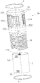
- FIG. 1 is a schematic diagram of an explosion structure of a tubular thick film heater with a protection function provided by an embodiment of the present invention
- FIG. 2 is a schematic diagram of the three-dimensional structure of FIG. 1;
- FIG. 3 is a schematic view of the top structure of FIG. 2;
- FIG. 4 is a cross-sectional view taken along line B-B in FIG. 3;
- FIG. 5 is a cross-sectional view taken along line C-C in FIG. 3;
- Figure 6 is a schematic diagram of the explosion structure of the tube heater assembly
- FIG. 7 is a schematic diagram of the three-dimensional structure of FIG. 6;
- FIG. 8 is a schematic diagram of the top structure of FIG. 7;
- FIG. 9 is a schematic diagram of the structure of the ring-shaped sealing end cover
- FIG. 10 is a cross-sectional view taken along line A-A in FIG. 8.
- tube heater assembly 1, inner tube; 11, helical diversion structure; 12, liquid inlet; 121, liquid inlet pipe; 13, liquid outlet; 131, liquid outlet pipe; 14, Flow channel; 20, heating assembly; 21, outer tube; 211, insulating medium layer; 22, heating circuit; 221, heating resistance; 222, electrode; 223, first temperature sensor; 224, second temperature sensor; 3 , Annular seal end cap; 31, inner round wall; 32, outer round wall; 33, upper sealing surface; 34, lower sealing surface; 40, upper cylinder; 41, upper cylinder side; 42, annular surface; 43, inner Torus; 44, mounting fixture; 45, flange; 46, first locking mechanism; 47, upper groove; 48, second positioning device; 51, first ring groove seal ring; 52, second ring Groove seal ring; 53, annular seal ring; 60, base; 61, second locking mechanism; 62, elastic connection piece; 63, lower groove; 64, first positioning device; 65, terminal block; 70, Seal the space.
- connection should be understood in a broad sense, for example, it can be fixedly connected or detachable. Or integrally connected; it can be a mechanical connection or an electrical connection; it can be a direct connection or an indirect connection through an intermediary, or the internal communication between two components.
- an embodiment of the present invention provides a tubular thick film heater with a protection function, including a tubular thick film heater protection device and a tubular heater assembly 10.
- the upper portion of the tube heater assembly 10 is sleeved in the upper groove 47 of the upper tube 40, and the lower portion of the tube heater assembly 10 is sleeved in the lower groove 63 of the base 60.
- the upper part of the tube heater assembly 10 is first sleeved in the groove of the first annular groove sealing ring 51, and then the first ring groove sealing ring 51 is sleeved in the upper groove 47; tube heating
- the lower part of the device assembly 10 is first sleeved in the groove of the second annular groove seal ring 52, and then the second annular groove seal ring 52 is sleeved in the lower groove 63.
- the tube heater assembly 10 and the tube thick film heater protection device can be made The connection is tighter, making a relatively isolated sealed space 70 composed of the surface of the heating circuit 22 of the tube heater assembly 10, the upper tube 40 and the base 60 more tightly sealed, reducing the influence of external air on the surface of the heating circuit 22 and reducing the sealing
- the heat loss in the space 70 improves the heating efficiency.
- the tubular thick film heater protection device is used to provide protection for the tubular heater assembly 10, including:
- the upper tube 40 includes an upper tube side surface 41 and an annular surface 42 which are provided in the inner space. Radius of the inner side of the inner tube 1 of the tube heater assembly 10; a flange 45 extends downward along the inner ring surface 43 of the torus 42, and the space between the flange 45 and the inner side wall of the upper tube side 41 constitutes an accommodation
- the upper groove 47 of the upper part of the tube heater assembly 10; the lower part of the upper side 41 of the cylinder is provided with a first locking mechanism 46;
- the central part of the base 60 is provided with a round hole for extending the outlet conduit 131 of the tube heater assembly 10, and the base 60 is also provided with a lower groove 63 whose inner side radius is smaller than the tube heater The radius of the inner side of the inner tube 1 of the assembly 10, the outer radius of the lower groove 63 is larger than the radius of the outer side of the outer tube 21 of the tube heater assembly 10; the base 60 is provided with an elastic connection piece 62, and the tube heater assembly When the lower part 10 is installed on the lower groove 63, the terminal contacts of the elastic connection piece 62 can be contacted with the electrode 222 on the outer tube 21 of the tube heater assembly 10; the terminal wall of the base 60 is provided with a terminal 65, The connecting terminal 65 is electrically connected to the elastic connecting piece 62, and the connecting terminal 65 can be externally connected to a power supply; the base 60 is provided with a second locking mechanism 61 that matches and locks with the first locking mechanism 46.
- the connecting terminal 65 can be directly provided with a power cord, and connected to the socket through
- the protective device of the tubular thick film heater provided by the embodiment of the present invention sets the tubular heater assembly 10 in the sealed space 70 formed by the upper tube 40 and the base 60 through the cooperation of the upper tube 40 and the base 60.
- the surface of the heating circuit 22 of the tube heater assembly 10 is relatively isolated from outside air. This not only avoids the influence of the external environment on the surface of the heating circuit 22 of the tube heater assembly 10, thereby affecting the heater, but also avoids the electric shock accidents that may occur when the surface of the heating circuit 22 of the tube heater assembly 10 is charged. Provide protection to operators.
- the upper tube 40 and the base 60 are preferably made of heat insulation and flame retardant materials.
- the shapes of the upper cylinder 40 and the base 60 are not specifically limited.
- the preferred embodiment of the upper cylinder 40 provided by the embodiment of the present invention is a cylinder, and the base 60 is a round base. Between the junction of the upper cylinder 40 and the base 60, a ring shape is further provided
- the sealing ring 53 that is, the annular sealing ring 53 wraps around the bottom of the upper side 41 of the cylinder.
- the bottom flange of the upper cylinder side can extend a circle of bottom flanges in the outward or inward direction. The bottom flange increases the contact area between the upper cylinder side 41 and the base 60, which can make the connection more stable and reliable.
- a groove for accommodating the annular sealing ring 53 may be provided on the bottom surface of the bottom flange and the upper surface of the base 60, the upper part of the annular sealing ring 53 is embedded in the groove of the bottom flange, and the lower part is embedded in the corresponding groove of the base Better sealing effect. Further reducing the heat loss can further improve the heating efficiency.
- the base 60 is also provided with a first positioning device 64.
- the first positioning device 64 is used to determine the matching position of the tube heater assembly 10 and the base 60, so that the terminal contacts of the elastic connection piece 62 can be connected with the tube heater assembly 10
- the electrode 222 on the outer tube 21 is contact-connected.
- the first positioning device 64 can be provided by various existing methods, such as setting an eye-catching mark on the base, and when the outlet conduit 131 of the tube heater assembly 10 is facing the mark, it means that it has been positioned and the purpose is to realize the tube
- the heater assembly 10 and the base 60 are positioned so as to realize the electrical connection between the elastic connection piece 62 and the electrode 222.
- the first positioning device 64 is a baffle plate
- the baffle plate can cause the tube heater assembly 10 to rotate along the lower groove 63 on the base 60 when the liquid outlet conduit 131 is in a corresponding position
- the baffle is designed to realize the positioning of the base and the tube heater assembly 10.
- the baffle can be further configured as an elastic baffle or a spring under the baffle. When the liquid discharge conduit 131 hits the baffle, it can continue to rotate until the elastic deformation of the baffle fixes the liquid discharge conduit 131. This design It further realizes a certain locking function for the tube heater assembly 10 and realizes more precise positioning.
- a second positioning device 48 is also provided on the inner ring flange 45 of the ring face downward, and the second positioning device 48 is used to determine the matching position of the tube heater assembly 10 and the upper tube 40 to realize the first locking mechanism 46 and the first The positions of the two locking mechanisms 61 match.
- the second positioning device 48 can be provided with an eye-catching mark on the torus 42 by various existing methods. When the liquid inlet conduit 121 of the tube heater assembly 10 is facing the mark, it means that the positioning has been performed. It is to realize the positioning of the tube heater assembly 10 and the upper tube 40, so as to realize the position matching of the first locking mechanism 46 and the second locking mechanism 61.
- the second positioning device 48 is a baffle plate, which can cause the tube heater assembly 10 to rotate at the corresponding position when the upper tube 40 rotates along the upper groove 47
- the baffle is designed to achieve the positioning of the upper tube 40 and the tube heater assembly 10.
- the baffle can be further configured as an elastic baffle or a spring under the baffle. When the liquid inlet conduit 121 encounters the baffle, it can continue to rotate until the elastic deformation of the baffle fixes the liquid inlet conduit 121. This design It further realizes a certain locking function for the tube heater assembly 10 and realizes more precise positioning.
- the first locking mechanism 46 and the second locking mechanism 61 can adopt the currently available locking technical solution.
- the first locking mechanism 46 is a protrusion with a groove
- the second locking mechanism 61 is Ring, sleeve the ring in the protruding groove to achieve locking.
- the first locking mechanism 46 includes a buckle with a bayonet
- the second locking mechanism 61 includes an elastic member clip with a protrusion.
- the second locking mechanism 61 includes a buckle with a bayonet
- the first locking mechanism 46 includes a resilient member clip with a protrusion.
- the protrusion can be matched with the bayonet of the buckle to realize the locking function.
- the protective device of the tubular thick film heater provided by the present invention, after the tubular heater assembly 10 is sheathed in the protective device, the feature of opening the protective device can be eliminated, that is, the design of the general tubular thick film heater It is reasonable and is not prone to failure. In case of occasional failure, it is basically in the overall replacement mode.
- the first locking mechanism 46 provided in the embodiment of the present invention is set as a buckle with a bayonet
- the buckle is set at all In the lower portion of the inner surface of the upper cylinder 40
- the second locking mechanism 61 is a second locking mechanism 61 including a resilient member clip with a protrusion.
- the elastic member clip is elastically deformed inwards.
- the upper cylinder continues to press down and the protrusion of the clamp reaches the groove of the buckle, the two cooperate To achieve locking. Since the buckle of the first locking mechanism 46 is provided in the upper cylinder, it is no longer possible to disengage the locking buckle from the buckle, so this locking is one-time non-removable and can be placed without being disassembled by a technician The problem.
- An installation fixing device 44 is also provided on the outer side wall of the upper tube 40.
- the installation fixing device 44 is used to realize the fixed connection of the entire tube-type thick film heater and the protective casing.
- the tube heater assembly 10 includes an inner tube 1, an outer tube 21, and an outer peripheral wall mounted on the outer tube 21
- the heating element 20 on the upper side, the outer wall of the inner tube 1 is provided with a spiral guide structure 11, the outer tube 21 is sleeved outside the spiral guide structure 11, the spiral guide structure 11 and the outer circumference of the inner tube 1
- the wall and the inner peripheral wall of the outer tube 21 together form a spiral flow path 14 through which the heated liquid passes.
- the setting of the radial gap facilitates the inner tube 1 equipped with the helical flow guide structure 11 to be sleeved into the outer tube 21. This facilitates the flow of liquid in the flow channel 14 and facilitates the sufficient heating of the flowing liquid. It should be noted that, it can be understood that the inner tube 1 is generally centrally located inside the outer tube 21, and this radial clearance is equivalent to half of the difference between the inner circumferential diameter of the outer tube 21 and the outer diameter D of the spiral guide structure 11 One.
- a flow channel 14 is formed between the inner tube 1 and the outer tube 21 where the spiral flow guiding structure 11 is arranged, and at least one end of the flow channel 14 is covered by a sealing end cap (both ends of the flow channel 14 in this embodiment) The openings are covered by sealed end caps).
- a liquid inlet 12 and a liquid outlet 13 are provided on the cavity wall of the flow channel.
- the sealed end cap is an annular sealed end cap 3, and the annular sealed end cap 3 includes an inner circular wall 31 and an outer circular wall 32 arranged concentrically, and an upper sealing surface 33 respectively connecting the upper part of the inner circular wall 31 and the upper part of the outer circular wall 32; And the lower sealing surface 34 connecting the lower part of the inner circular wall 31 and the lower part of the outer circular wall 32 respectively, the inner circular wall 31 is sealed and fixed to the end of the outer peripheral wall of the inner tube 1, and the outer circular wall 32 is sealed to the end of the inner peripheral wall of the outer tube 21 fixed.
- the heating assembly 20 installed on the outer peripheral wall of the outer tube 21 heats the flowing liquid.
- the heat generated by the heating assembly 20 passes through the outer tube 21 and exchanges heat with the liquid in the flow channel 14 to achieve the liquid Continuous heating, and the ring-shaped sealing end caps 3 all close the flow channel 14 formed by the inner tube 1 and the outer tube 21 by welding, so that the tube heater assembly 10 can withstand high temperature and high pressure environment.
- the heated liquid flows out from the liquid outlet 13.
- a water pump is arranged at the liquid inlet 12 to continuously deliver pressurized liquid into the spiral flow channel 14.
- the technical solution of the present invention is to design the sealing end cap as an annular sealing end cap 3, the annular sealing end cap 3 includes only four faces, an inner circular wall 31 and an outer circular wall 32 that are concentrically disposed, and an upper sealing surface 33 and the lower sealing surface 34, the above four surfaces are all regular surfaces, and can be formed only by stamping or cutting processes. It is not like U-shaped seal end that requires multiple stamping and stretching to form. Therefore, the processing technology is extremely simplified, the processing control technology is simple, the processing cost is low, and the processing efficiency can be greatly improved.
- the inner circular wall and the outer peripheral wall end of the inner tube are sealed by welding, and the outer circular wall and the inner peripheral wall end of the outer tube 21 are sealed by welding.
- Laser welding or argon arc welding is preferred.
- the range of the predetermined radial gap between the inner peripheral wall of the outer tube 21 and the spiral guide structure 11 is set to be no more than 1.0 mm, which is convenient for the inner tube 1 provided with the spiral guide structure 11 While being inserted into the outer tube 21, it also avoids that the radial gap is too large to cause the liquid to directly flow through the radial gap to the liquid outlet 13 along the length of the inner tube 1 without passing through the outer wall of the inner tube 1
- the spiral diversion structure 11 conducts diversion and cannot fully heat the liquid; or the radial gap is too small, causing the liquid to stagnate in the spiral diversion structure 11 and receiving continuous heating of the heating assembly 20, causing Local overheating will result in the vaporization of the stagnant liquid at this point to produce steam discharge, which in turn will cause the liquid discharge from the liquid outlet 13 to be discontinuous and discharge with a large number of bubbles.
- the embodiment provided by the present invention has been proved by a large number of experiments that when the radial gap is set in the range of 0.00mm-1.0mm, the liquid can be fully heated, the heating effect is good, and the liquid can be prevented from being overheated while ensuring The liquid flows smoothly, avoiding the generation of large bubbles.
- the spiral diversion structure 11 is formed by a spiral metal wire sheathed on the inner tube 1, and the spiral metal wire is directly exposed to contact with the liquid.
- the spiral metal wire should be selected not to be rusty and harmless to the human body Metal material. The phenomenon that, for example, the encapsulation glue made of silicone material blisters due to heat and aging and blocks the flow channel 14 is avoided, the service life of the heating device is improved, and the food safety is also improved.
- the spiral metal wire is configured as a stainless steel wire, and the stainless steel wire is welded to the outer peripheral wall of the inner tube 1 to avoid noise generated by shaking in the flow channel 14.
- the axial cross-sectional shape of the spiral wire is triangular, trapezoidal or rectangular, and the bottom edge of the triangular or trapezoid is welded to the outer peripheral wall of the inner tube 1.
- the flow channel 14 formed in this way has a simple structure, is easy to produce, and guide Streaming performance is more stable.
- both ends of the inner tube 1 and the outer tube 21 are flush with each other, which is convenient for laser welding to seal the inner circular wall of the ring-shaped end cap 3 and the outer peripheral wall of the inner tube 1, and the outer circular wall and the outer tube 21 The ends of the inner peripheral wall are sealed by laser welding.
- both the inner tube 1 and the outer tube 21 are provided as stainless steel tubes.
- the heating module 20 includes an insulating dielectric layer 211 disposed on the outer peripheral wall of the outer tube 21 and a heating circuit 22 disposed on the insulating dielectric layer 211.
- the insulating medium is printed on the outer peripheral wall of the outer tube 21 In layer 211, the heat generated by the heating circuit 22 is used to exchange heat with the liquid flowing in the spiral flow path 14.
- the wall thickness of the outer tube 21 ranges from 0.5 mm to 1 mm
- the wall thickness of the inner tube 1 ranges from 0.3 mm to 1 mm.
- the heating circuit 22 includes a plurality of heating resistors 221 and electrodes 222 fixed on the insulating dielectric layer 211. Both ends of the heating resistor 221 are electrically connected to the electrodes 222, so that the electrode 222 is connected to a power supply for The heating resistor 221 generates heat.
- each heating resistor 221 coincides with the longitudinal direction of the outer tube 21, and a water pump (not shown) is connected to the liquid inlet 12.
- the tube heater assembly 10 further includes a first temperature sensor 223, and a first controller electrically connected to the first temperature sensor 223 (eg, PCB board control in this embodiment), the first temperature sensor 223
- the outer tube 21 is arranged at a position close to the liquid outlet 13. As can be seen from the figure, in this embodiment, the liquid outlet 13 is opened on the inner tube 1, the first temperature sensor 223 is as close as possible to the liquid outlet 13, and can be disposed on the outer tube 21 closest to the liquid outlet 13 Radial position.
- the first temperature sensor 223 can approximately detect the liquid temperature of the liquid outlet 13 by detecting the temperature of the cylinder wall of the outer tube 21 close to the liquid outlet 13.
- the PCB board controls according to the temperature information sent by the first temperature sensor 223 The pumping speed of the water pump and / or the heating power of the heating resistor 221.
- the first temperature sensor 223 is disposed close to the liquid outlet 13 and is far away from the heating resistor 221 in the axial direction, so as to accurately detect the temperature of the liquid in the liquid outlet 13. In this way, the first temperature sensor 223 is used to detect the temperature of the liquid and feed it back to the PCB board.
- the PCB board is compared with the temperature required by the user to set the liquid according to the measured liquid temperature data to automatically adjust the heating resistance 221 Heating power, or by controlling the water pump to adjust the flow rate of the liquid entering the flow channel 14, thereby achieving accurate control of the liquid temperature.
- a plurality of heating resistors 221 are distributed around the outer peripheral wall of the outer tube 21, and preferably can be arranged approximately uniformly, so that the heating resistor 221 is directly opposite the flow channel 14 Liquid to transfer heat to the flowing liquid in time.
- the tube heater assembly 10 further includes a second temperature sensor 224, and a second controller electrically connected to the second temperature sensor 224 (the second controller, for example, also uses the PCB board described in this embodiment Control), the second temperature sensor 224 is disposed on the outer tube 21 and is located near the heating resistor, used to detect the temperature of the outer tube where the second temperature sensor 224 is located, and the second controller (PCB board) is used to receive the second The temperature of the outer tube sent by the temperature sensor 224, and when the temperature of the outer tube is higher than the first preset temperature threshold within the first preset heating time period, the heating circuit 22 is controlled to be disconnected and / or an empty burn reminder is issued.
- the second controller for example, also uses the PCB board described in this embodiment Control
- the PCB board can control the heating circuit to open according to the temperature information of the outer tube sent by the second temperature sensor 224, and / or issue Remind message of temperature protection, so as to realize dry burning protection, to prevent the heating assembly 20 from being burned.
- the first temperature-sensing sensor 223 and the second temperature-sensing sensor 224 are arranged along the length direction of the outer tube 21, which is convenient for the process of burning and laser trimming.
- the second temperature sensor 224 may be disposed closer to the liquid outlet 13 relative to the liquid inlet 12, preferably, the first The temperature sensor 223 is disposed closer to the liquid outlet 13 than the second temperature sensor 224.
- the power density of the heating resistor 221 close to the second temperature sensor 224 may be greater than the power density of the heating resistor circumferentially far from the second temperature sensor 224.
- the second The controller (PCB board) is also used to receive the temperature of the outer tube from the second temperature sensor 224, and to control when the received temperature of the outer tube is higher than the second preset temperature threshold within the second preset heating time period
- the heating circuit is open, and / or a warning message for scale protection is issued.
- the specific scale detection principle is as follows: by making the working temperature (related to the power density) of the heating resistor 221 near the second temperature sensor 224 higher than the heating resistor 221 in other regions, the scale is firstly at the second temperature The periphery of the sensor 224 begins to accumulate, and the amount of scale accumulation will be more than that of other areas.
- the heat resistance 221 continues to flow
- the heat generated by the heating resistor 221 at the scale accumulation site cannot be transferred to the liquid longitudinally through the stainless steel outer tube 21 due to the presence of scale, thereby causing the temperature of the wall of the outer tube 21 at that place Increase, so the second temperature sensor 224 detects the temperature of the outer tube at this time and feeds it back to the PCB board, sends a message to remind the user that the scale needs to be cleaned, and controls the heating circuit to open to stop heating, which effectively prevents the buildup caused by scale
- the heating resistor 221 is locally overheated, which may cause burnout.
- the line width of the heating resistor around the second temperature sensor 224 can be reduced.
- the second temperature sensor 224 has the function of integrated detection, which can realize the functions of anti-drying protection and scale detection reminder, and optimizes the function of the tube heater assembly 10.
- the scale protection limit protection method is as follows:
- the second temperature sensor 224 starts to detect the temperature of the outer tube, and the temperature of the outer tube and the second controller (such as used in this embodiment The above PCB board control) compares the preset second preset temperature threshold, and generates an execution command when the temperature of the outer tube reaches the second preset temperature threshold.
- the electrode 222 is controlled to be disconnected according to the execution command, and an information reminder of the scale limit protection is issued to remind the user to clean the scale accumulated near the liquid outlet 13.
- the temperature detected by the second temperature sensor 224 is 55 to 91 ° C, and as the heating time increases, the scale around the second temperature sensor 224 begins to accumulate scale.
- the temperature of the heating resistor rises, and the heat generated by it is transferred laterally to the second temperature sensor 224, which detects the temperature of the outer tube at this time and feeds it back to the PCB board.
- a preset protection threshold of 103 ° C is compared.
- the PCB board controls to disconnect the power supply and prompts the scale limit protection to remind the user that the scale needs to be cleaned.
- the liquid inlet 12 and the liquid outlet 13 are both provided on the inner tube 1, the liquid inlet conduit 121 is arranged at the position of the inner tube 1 corresponding to the liquid inlet 12, and the inner tube 1 corresponds to the liquid outlet A liquid outlet duct 131 is arranged at the position of 13, and at least the liquid inlet duct 121 is arranged obliquely with respect to the center line of the inner tube 1 so that the liquid can easily flow in.
- the liquid inlet duct 121 and the liquid outlet duct 131 are installed in a cavity formed in the center of the inner tube 1.
- the tube heater assembly 10 provided by the embodiment of the present invention has a simple sealed connection structure, low manufacturing cost, stable performance under high temperature and high pressure environment, long service life, stainless steel spiral flow channel 14 with high edible safety factor, stable outlet temperature, and The scale detection is increased, the life of the heating element is increased, and the value of application and promotion is high.
Landscapes
- Engineering & Computer Science (AREA)
- Physics & Mathematics (AREA)
- Thermal Sciences (AREA)
- Mechanical Engineering (AREA)
- General Engineering & Computer Science (AREA)
- Chemical & Material Sciences (AREA)
- Combustion & Propulsion (AREA)
- Geometry (AREA)
- Resistance Heating (AREA)
- Instantaneous Water Boilers, Portable Hot-Water Supply Apparatuses, And Control Of Portable Hot-Water Supply Apparatuses (AREA)
Abstract
L'invention concerne un dispositif de protection d'un appareil de chauffage à film épais tubulaire, le dispositif comportant : un cylindre supérieur (40), le cylindre supérieur (40) comportant une face latérale (41) de cylindre supérieur et une face annulaire circulaire (42) ; une face annulaire externe de la face annulaire circulaire (42) est reliée en une seule pièce à une partie supérieure de la face latérale (41) du cylindre supérieur et s'étend vers le bas le long d'une face annulaire interne (43) de la face annulaire circulaire (42) afin de former une bride (45), un espace entre la bride (45) et une paroi latérale interne de la face latérale (41) du cylindre supérieur formant une rainure supérieure (47) ; une base (60), la base (60) étant munie d'une rainure inférieure (63), une pièce de contact élastique (62) étant agencée sur la base (60), et un contact de borne de la pièce de contact élastique (62) étant en connexion avec une électrode (222) ; la base (60) est munie d'une borne (65) pour fils électriques, la borne (65) pour fils électriques étant connectée électriquement à la pièce de contact élastique (62), et la borne (65) pour fils électriques étant connectée extérieurement à une source d'alimentation électrique. L'appareil de chauffage à film épais tubulaire, qui possède une fonction de protection, empêche un environnement externe d'avoir une incidence sur la surface d'un circuit de chauffage (22) d'un ensemble chauffant tubulaire (10), ayant ainsi une incidence sur l'efficacité de chauffage, protégeant l'appareil de chauffage, et évitant également, pendant les phases de travail de l'ensemble chauffant tubulaire (10), un choc électrique pouvant être provoqué par l'électrification de la surface du circuit de chauffage (22) de l'ensemble chauffant tubulaire, ce qui permet de protéger l'opérateur.
Priority Applications (3)
| Application Number | Priority Date | Filing Date | Title |
|---|---|---|---|
| EP18938483.7A EP3875868B1 (fr) | 2018-11-01 | 2018-11-29 | Dispositif de protection d'appareil de chauffage à film épais tubulaire et appareil de chauffage à film épais tubulaire |
| US17/242,243 US12098866B2 (en) | 2018-11-01 | 2021-04-27 | Tubular thick film heater protection apparatus and tubular thick film heater |
| US18/776,255 US20240373515A1 (en) | 2018-11-01 | 2024-07-18 | Tubular thick film heater protection apparatus and tubular thick film heater |
Applications Claiming Priority (2)
| Application Number | Priority Date | Filing Date | Title |
|---|---|---|---|
| CN201811295678.1 | 2018-11-01 | ||
| CN201811295678.1A CN109458729B (zh) | 2018-11-01 | 2018-11-01 | 管式厚膜加热器保护装置及管式厚膜加热器 |
Related Child Applications (1)
| Application Number | Title | Priority Date | Filing Date |
|---|---|---|---|
| US17/242,243 Continuation US12098866B2 (en) | 2018-11-01 | 2021-04-27 | Tubular thick film heater protection apparatus and tubular thick film heater |
Publications (1)
| Publication Number | Publication Date |
|---|---|
| WO2020087622A1 true WO2020087622A1 (fr) | 2020-05-07 |
Family
ID=65609116
Family Applications (1)
| Application Number | Title | Priority Date | Filing Date |
|---|---|---|---|
| PCT/CN2018/118201 Ceased WO2020087622A1 (fr) | 2018-11-01 | 2018-11-29 | Dispositif de protection d'appareil de chauffage à film épais tubulaire et appareil de chauffage à film épais tubulaire |
Country Status (4)
| Country | Link |
|---|---|
| US (1) | US12098866B2 (fr) |
| EP (1) | EP3875868B1 (fr) |
| CN (1) | CN109458729B (fr) |
| WO (1) | WO2020087622A1 (fr) |
Cited By (2)
| Publication number | Priority date | Publication date | Assignee | Title |
|---|---|---|---|---|
| CN115854546A (zh) * | 2022-12-09 | 2023-03-28 | 上海至纯洁净系统科技股份有限公司 | 在线加热装置 |
| CN118499939A (zh) * | 2024-07-18 | 2024-08-16 | 江苏荣亿达温控科技有限公司 | 一种智能控温的油温机及其控制方法 |
Families Citing this family (15)
| Publication number | Priority date | Publication date | Assignee | Title |
|---|---|---|---|---|
| CN110000975B (zh) * | 2019-05-07 | 2023-06-30 | 安徽安凯汽车股份有限公司 | 一种节能型纯电动客车用薄膜加热器 |
| CN112577186B (zh) * | 2019-09-27 | 2025-04-15 | 浙江绍兴苏泊尔生活电器有限公司 | 加热供水装置及开水器 |
| CN111102735A (zh) * | 2019-12-26 | 2020-05-05 | 佛山市海德精工电子科技有限公司 | 用于液体加热装置的内管及液体加热装置、制造方法 |
| CN113286393B (zh) * | 2020-10-31 | 2024-08-20 | 东海县晶明照明电器有限公司 | 便于聚热的卤素加热管 |
| CN113966018A (zh) * | 2021-11-17 | 2022-01-21 | 中山赛特奥日用科技有限公司 | 一种发热体及其制造方法 |
| CN114353314A (zh) * | 2022-01-18 | 2022-04-15 | 东莞市东思电子技术有限公司 | 一种内置螺纹导流水道的发热圆管组件及其制备工艺 |
| CN115060003A (zh) * | 2022-07-02 | 2022-09-16 | 安徽苏立科技股份有限公司 | 加热器水道及应用该加热器水道的圆管加热器组件 |
| CN116347680B (zh) * | 2023-03-16 | 2026-04-21 | 深圳英集芯科技股份有限公司 | 防干烧控制电路 |
| CN116792938B (zh) * | 2023-04-28 | 2026-03-03 | 镇江东方电热有限公司 | 一种大功率直接电阻式加热元件及其使用方法 |
| WO2024250267A1 (fr) * | 2023-06-09 | 2024-12-12 | 深圳和而泰新材料科技有限公司 | Dispositif de chauffage et appareil pour boisson chaude |
| CN117433342B (zh) * | 2023-12-18 | 2024-03-12 | 江苏海鹏防腐设备有限公司 | 一种耐腐蚀的板式换热器及其换热方法 |
| CN118031414B (zh) * | 2024-04-11 | 2024-06-11 | 厦门宝益科技有限公司 | 一种可高效维持介质良性换热的厚膜加热器件 |
| CN119042797B (zh) * | 2024-10-31 | 2025-01-28 | 上海耀杉电子科技有限公司 | 膜加热散热结构 |
| CN119393900B (zh) * | 2025-01-06 | 2025-03-18 | 江苏沃凯氟精密智造有限公司 | 一种液体加热器 |
| CN120111728B (zh) * | 2025-05-09 | 2025-07-04 | 宁波市扬天磁能科技有限公司 | 一种绝电瞬热多层复合厚膜发热体 |
Citations (6)
| Publication number | Priority date | Publication date | Assignee | Title |
|---|---|---|---|---|
| US20020001461A1 (en) * | 2000-06-29 | 2002-01-03 | Valerio Bresolin | Thermostatic heating device for liquids, provided with a recirculation pump |
| US20150016811A1 (en) * | 2013-07-09 | 2015-01-15 | Cast Aluminum Solutions, LLC | Circulation heater |
| CN205381971U (zh) * | 2016-02-05 | 2016-07-13 | 佛山市云米电器科技有限公司 | 一种带有加热装置的净水系统 |
| CN205481783U (zh) * | 2016-02-05 | 2016-08-17 | 佛山市云米电器科技有限公司 | 一种液体加热装置的密封支架结构 |
| CN108449814A (zh) * | 2018-05-17 | 2018-08-24 | 佛山市海德精工电子科技有限公司 | 一种加热器 |
| CN108458474A (zh) * | 2018-02-05 | 2018-08-28 | 佛山市海德精工电子科技有限公司 | 一种液体加热装置 |
Family Cites Families (21)
| Publication number | Priority date | Publication date | Assignee | Title |
|---|---|---|---|---|
| CA1113533A (fr) * | 1978-10-13 | 1981-12-01 | Lynne E. Windsor | Dispositif de blocage pour thermoplongeur de moteur |
| US4865014A (en) * | 1989-02-16 | 1989-09-12 | Nelson Thomas E | Water heater and method of fabricating same |
| CN2260983Y (zh) * | 1996-02-13 | 1997-08-27 | 杨荣楷 | 真空镀电热膜热水器 |
| US6632100B1 (en) * | 1997-04-23 | 2003-10-14 | Anthony, Inc. | Lighting system method and apparatus socket assembly lamp insulator assembly and components thereof |
| AU8730501A (en) * | 1997-04-23 | 2002-01-31 | Anthony, Inc. | A ballast circuit |
| DE202005004360U1 (de) * | 2005-02-21 | 2005-05-25 | Wolf Gmbh | Wärmetauscher |
| DE102007034370A1 (de) * | 2007-07-24 | 2009-01-29 | Bleckmann Gmbh & Co. Kg | Kompakte hochdruckfähige Spiraldurchfluss-Heizeinheit |
| CA2639260A1 (fr) * | 2008-04-18 | 2009-10-18 | Sang Pil Choi | Reservoir d'eau chaude separable |
| US20100046934A1 (en) * | 2008-08-19 | 2010-02-25 | Johnson Gregg C | High thermal transfer spiral flow heat exchanger |
| JP2011064449A (ja) * | 2009-08-28 | 2011-03-31 | Sang Pil Choi | 気密保持部が備えられた水槽 |
| CN202637235U (zh) * | 2012-07-02 | 2013-01-02 | 黄胜涛 | 防爆型电热水袋 |
| CN103152846B (zh) * | 2013-03-13 | 2014-06-11 | 沈闽江 | 厚膜加热器 |
| CN203392401U (zh) * | 2013-08-18 | 2014-01-15 | 河北巨鑫输送工程有限公司 | 一种托辊密封 |
| US20160366940A1 (en) * | 2014-02-28 | 2016-12-22 | Kimree Hi-Tech Inc. | Electronic cigarette and electronic cigarette atomization control method |
| CN105546805B (zh) * | 2016-02-05 | 2018-10-16 | 广西桂仪科技有限公司 | 一种液体加热装置 |
| CN205939663U (zh) * | 2016-07-25 | 2017-02-08 | 宁波励科智能科技有限公司 | 一种改进后的电热水器 |
| CN206603236U (zh) * | 2017-01-10 | 2017-11-03 | 深圳市艾维普思科技股份有限公司 | 电子烟 |
| CN106595030A (zh) * | 2017-03-03 | 2017-04-26 | 佛山吉宝信息科技有限公司 | 一种新型即热式恒温电热水器 |
| CN206739592U (zh) * | 2017-04-05 | 2017-12-12 | 胡小庆 | 一种电磁加热发热体及具有其的热水器、液体加热器 |
| CN209541145U (zh) * | 2018-11-01 | 2019-10-25 | 佛山市海德精工电子科技有限公司 | 管式厚膜加热器保护装置及管式厚膜加热器 |
| CN109682072B (zh) * | 2019-02-01 | 2024-05-03 | 宁波飞羽集团有限公司 | 电热水器 |
-
2018
- 2018-11-01 CN CN201811295678.1A patent/CN109458729B/zh active Active
- 2018-11-29 EP EP18938483.7A patent/EP3875868B1/fr active Active
- 2018-11-29 WO PCT/CN2018/118201 patent/WO2020087622A1/fr not_active Ceased
-
2021
- 2021-04-27 US US17/242,243 patent/US12098866B2/en active Active
Patent Citations (6)
| Publication number | Priority date | Publication date | Assignee | Title |
|---|---|---|---|---|
| US20020001461A1 (en) * | 2000-06-29 | 2002-01-03 | Valerio Bresolin | Thermostatic heating device for liquids, provided with a recirculation pump |
| US20150016811A1 (en) * | 2013-07-09 | 2015-01-15 | Cast Aluminum Solutions, LLC | Circulation heater |
| CN205381971U (zh) * | 2016-02-05 | 2016-07-13 | 佛山市云米电器科技有限公司 | 一种带有加热装置的净水系统 |
| CN205481783U (zh) * | 2016-02-05 | 2016-08-17 | 佛山市云米电器科技有限公司 | 一种液体加热装置的密封支架结构 |
| CN108458474A (zh) * | 2018-02-05 | 2018-08-28 | 佛山市海德精工电子科技有限公司 | 一种液体加热装置 |
| CN108449814A (zh) * | 2018-05-17 | 2018-08-24 | 佛山市海德精工电子科技有限公司 | 一种加热器 |
Non-Patent Citations (1)
| Title |
|---|
| See also references of EP3875868A4 * |
Cited By (2)
| Publication number | Priority date | Publication date | Assignee | Title |
|---|---|---|---|---|
| CN115854546A (zh) * | 2022-12-09 | 2023-03-28 | 上海至纯洁净系统科技股份有限公司 | 在线加热装置 |
| CN118499939A (zh) * | 2024-07-18 | 2024-08-16 | 江苏荣亿达温控科技有限公司 | 一种智能控温的油温机及其控制方法 |
Also Published As
| Publication number | Publication date |
|---|---|
| CN109458729A (zh) | 2019-03-12 |
| EP3875868B1 (fr) | 2023-06-07 |
| US12098866B2 (en) | 2024-09-24 |
| EP3875868C0 (fr) | 2023-06-07 |
| EP3875868A4 (fr) | 2022-04-06 |
| CN109458729B (zh) | 2025-06-03 |
| EP3875868A1 (fr) | 2021-09-08 |
| US20210247101A1 (en) | 2021-08-12 |
Similar Documents
| Publication | Publication Date | Title |
|---|---|---|
| WO2020087622A1 (fr) | Dispositif de protection d'appareil de chauffage à film épais tubulaire et appareil de chauffage à film épais tubulaire | |
| WO2019148785A1 (fr) | Dispositif de chauffage de liquide | |
| CN215864028U (zh) | 燃气热水器 | |
| US20240373515A1 (en) | Tubular thick film heater protection apparatus and tubular thick film heater | |
| CN110801157A (zh) | 一种液体加热装置 | |
| CN207921551U (zh) | 燃气接头及燃气热水器 | |
| CN209541145U (zh) | 管式厚膜加热器保护装置及管式厚膜加热器 | |
| US11306945B2 (en) | Heating system for heating a fluid medium | |
| CN114738321B (zh) | 一种刀片式加热泵盖及加热泵 | |
| KR20150098862A (ko) | 냉각수 가열식 히터 | |
| CN105509020A (zh) | 蒸汽发生器、挂烫机和蒸汽发生器的发热器 | |
| CN212565894U (zh) | 防干烧燃气灶 | |
| CN218883963U (zh) | 一种燃烧器及灶具 | |
| CN115899694A (zh) | 一种燃烧器及灶具 | |
| CN223896032U (zh) | 灶具 | |
| CN215175958U (zh) | 高安全性即热式水加热器 | |
| JPH0456216B2 (fr) | ||
| CN106658766B (zh) | 船用电加热器装置 | |
| CN222146373U (zh) | 用于电动车辆的流体加热装置 | |
| CN219101619U (zh) | 一种新型厚膜盘式加热泵 | |
| CN219530806U (zh) | 蒸汽发生单元、蒸汽发生器及蒸汽清洁设备 | |
| CN222279954U (zh) | 一种供暖系统中温度传感器用浸入套 | |
| CN223554669U (zh) | 一种加热组件及咖啡机 | |
| CN222459826U (zh) | 加热装置 | |
| CN210718026U (zh) | 全智能多燃料热水采暖机 |
Legal Events
| Date | Code | Title | Description |
|---|---|---|---|
| 121 | Ep: the epo has been informed by wipo that ep was designated in this application |
Ref document number: 18938483 Country of ref document: EP Kind code of ref document: A1 |
|
| NENP | Non-entry into the national phase |
Ref country code: DE |
|
| ENP | Entry into the national phase |
Ref document number: 2018938483 Country of ref document: EP Effective date: 20210601 |