WO2020090110A1 - Système d'affichage et procédé de commande - Google Patents
Système d'affichage et procédé de commande Download PDFInfo
- Publication number
- WO2020090110A1 WO2020090110A1 PCT/JP2018/040841 JP2018040841W WO2020090110A1 WO 2020090110 A1 WO2020090110 A1 WO 2020090110A1 JP 2018040841 W JP2018040841 W JP 2018040841W WO 2020090110 A1 WO2020090110 A1 WO 2020090110A1
- Authority
- WO
- WIPO (PCT)
- Prior art keywords
- display
- unit
- identification number
- identification information
- display devices
- Prior art date
- Legal status (The legal status is an assumption and is not a legal conclusion. Google has not performed a legal analysis and makes no representation as to the accuracy of the status listed.)
- Ceased
Links
Images


Classifications
-
- G—PHYSICS
- G06—COMPUTING OR CALCULATING; COUNTING
- G06F—ELECTRIC DIGITAL DATA PROCESSING
- G06F3/00—Input arrangements for transferring data to be processed into a form capable of being handled by the computer; Output arrangements for transferring data from processing unit to output unit, e.g. interface arrangements
- G06F3/14—Digital output to display device ; Cooperation and interconnection of the display device with other functional units
- G06F3/1423—Digital output to display device ; Cooperation and interconnection of the display device with other functional units controlling a plurality of local displays, e.g. CRT and flat panel display
-
- G—PHYSICS
- G09—EDUCATION; CRYPTOGRAPHY; DISPLAY; ADVERTISING; SEALS
- G09G—ARRANGEMENTS OR CIRCUITS FOR CONTROL OF INDICATING DEVICES USING STATIC MEANS TO PRESENT VARIABLE INFORMATION
- G09G3/00—Control arrangements or circuits, of interest only in connection with visual indicators other than cathode-ray tubes
- G09G3/20—Control arrangements or circuits, of interest only in connection with visual indicators other than cathode-ray tubes for presentation of an assembly of a number of characters, e.g. a page, by composing the assembly by combination of individual elements arranged in a matrix no fixed position being assigned to or needed to be assigned to the individual characters or partial characters
- G09G3/34—Control arrangements or circuits, of interest only in connection with visual indicators other than cathode-ray tubes for presentation of an assembly of a number of characters, e.g. a page, by composing the assembly by combination of individual elements arranged in a matrix no fixed position being assigned to or needed to be assigned to the individual characters or partial characters by control of light from an independent source
- G09G3/36—Control arrangements or circuits, of interest only in connection with visual indicators other than cathode-ray tubes for presentation of an assembly of a number of characters, e.g. a page, by composing the assembly by combination of individual elements arranged in a matrix no fixed position being assigned to or needed to be assigned to the individual characters or partial characters by control of light from an independent source using liquid crystals
-
- H—ELECTRICITY
- H04—ELECTRIC COMMUNICATION TECHNIQUE
- H04M—TELEPHONIC COMMUNICATION
- H04M1/00—Substation equipment, e.g. for use by subscribers
- H04M1/72—Mobile telephones; Cordless telephones, i.e. devices for establishing wireless links to base stations without route selection
- H04M1/724—User interfaces specially adapted for cordless or mobile telephones
- H04M1/72403—User interfaces specially adapted for cordless or mobile telephones with means for local support of applications that increase the functionality
- H04M1/72409—User interfaces specially adapted for cordless or mobile telephones with means for local support of applications that increase the functionality by interfacing with external accessories
- H04M1/72415—User interfaces specially adapted for cordless or mobile telephones with means for local support of applications that increase the functionality by interfacing with external accessories for remote control of appliances
-
- G—PHYSICS
- G09—EDUCATION; CRYPTOGRAPHY; DISPLAY; ADVERTISING; SEALS
- G09G—ARRANGEMENTS OR CIRCUITS FOR CONTROL OF INDICATING DEVICES USING STATIC MEANS TO PRESENT VARIABLE INFORMATION
- G09G2354/00—Aspects of interface with display user
-
- G—PHYSICS
- G09—EDUCATION; CRYPTOGRAPHY; DISPLAY; ADVERTISING; SEALS
- G09G—ARRANGEMENTS OR CIRCUITS FOR CONTROL OF INDICATING DEVICES USING STATIC MEANS TO PRESENT VARIABLE INFORMATION
- G09G2360/00—Aspects of the architecture of display systems
- G09G2360/14—Detecting light within display terminals, e.g. using a single or a plurality of photosensors
- G09G2360/141—Detecting light within display terminals, e.g. using a single or a plurality of photosensors the light conveying information used for selecting or modulating the light emitting or modulating element
-
- G—PHYSICS
- G09—EDUCATION; CRYPTOGRAPHY; DISPLAY; ADVERTISING; SEALS
- G09G—ARRANGEMENTS OR CIRCUITS FOR CONTROL OF INDICATING DEVICES USING STATIC MEANS TO PRESENT VARIABLE INFORMATION
- G09G2360/00—Aspects of the architecture of display systems
- G09G2360/14—Detecting light within display terminals, e.g. using a single or a plurality of photosensors
- G09G2360/145—Detecting light within display terminals, e.g. using a single or a plurality of photosensors the light originating from the display screen
-
- G—PHYSICS
- G09—EDUCATION; CRYPTOGRAPHY; DISPLAY; ADVERTISING; SEALS
- G09G—ARRANGEMENTS OR CIRCUITS FOR CONTROL OF INDICATING DEVICES USING STATIC MEANS TO PRESENT VARIABLE INFORMATION
- G09G2370/00—Aspects of data communication
- G09G2370/04—Exchange of auxiliary data, i.e. other than image data, between monitor and graphics controller
- G09G2370/042—Exchange of auxiliary data, i.e. other than image data, between monitor and graphics controller for monitor identification
-
- G—PHYSICS
- G09—EDUCATION; CRYPTOGRAPHY; DISPLAY; ADVERTISING; SEALS
- G09G—ARRANGEMENTS OR CIRCUITS FOR CONTROL OF INDICATING DEVICES USING STATIC MEANS TO PRESENT VARIABLE INFORMATION
- G09G2370/00—Aspects of data communication
- G09G2370/06—Consumer Electronics Control, i.e. control of another device by a display or vice versa
-
- G—PHYSICS
- G09—EDUCATION; CRYPTOGRAPHY; DISPLAY; ADVERTISING; SEALS
- G09G—ARRANGEMENTS OR CIRCUITS FOR CONTROL OF INDICATING DEVICES USING STATIC MEANS TO PRESENT VARIABLE INFORMATION
- G09G3/00—Control arrangements or circuits, of interest only in connection with visual indicators other than cathode-ray tubes
- G09G3/001—Control arrangements or circuits, of interest only in connection with visual indicators other than cathode-ray tubes using specific devices not provided for in groups G09G3/02 - G09G3/36, e.g. using an intermediate record carrier such as a film slide; Projection systems; Display of non-alphanumerical information, solely or in combination with alphanumerical information, e.g. digital display on projected diapositive as background
Definitions
- the present invention relates to a display system and a control method.
- each of the plurality of display devices displays an image code indicating identification information for identifying the display device on the screen, and based on the plurality of image codes, the respective display devices are displayed. , Is associated with the position of the display image.
- a complicated operation such as setting identification information in advance in each display device is required, and convenience may be impaired.
- the present invention has been made to solve the above problems, and an object thereof is to provide a display system and a control method capable of improving convenience.
- one embodiment of the present invention includes a plurality of display devices and a mobile device which operates the plurality of display devices, and each of the plurality of display devices is an identification for identifying its own device.
- An identification information generation unit that generates information
- a display control unit that causes the display unit to output the output information indicating the identification information generated by the identification information generation unit, wherein the portable device is the one of the plurality of display devices.
- the identification information corresponding to each of the plurality of display devices is detected and detected. It is a display system provided with a device control part which matches the above-mentioned discernment information and each arrangement of the above-mentioned plurality of display devices.
- one embodiment of the present invention is a method for controlling a display system including a plurality of display devices and a mobile device that operates the plurality of display devices, each of the plurality of display devices identifying its own device.
- Identification information generating step for generating identification information
- a display control step for causing each of the plurality of display devices to output from the display section output information indicating the identification information generated by the identification information generating step,
- An image capturing step in which a device captures an image displayed by the display unit of the plurality of display devices; and the mobile device, based on the output information included in the image captured in the image capturing step,
- a machine that detects the identification information corresponding to each of the display devices and associates the detected identification information with the respective arrangements of the plurality of display devices.
- a control method and a control step for controlling a display system including a plurality of display devices and a mobile device that operates the plurality of display devices, each of the plurality of display devices identifying its own device.
- Identification information generating step for
- 1 is an external view showing an example of a display system according to a first embodiment. It is a block diagram which shows an example of the display system by 1st Embodiment. It is a block diagram which shows an example of the display part in 1st Embodiment. It is a figure which shows the data example of an identification number list storage part in 1st Embodiment. It is a figure which shows an example of the captured image of an identification number pattern in 1st Embodiment. It is a figure which shows an example of the operation screen of the portable device in 1st Embodiment. 6 is a flowchart illustrating an example of operation of the mobile device according to the first exemplary embodiment.
- 5 is a flowchart showing an example of an identification number setting process in the mobile device of the first embodiment.
- 6 is a flowchart showing an example of an operation process of a display device in the mobile device of the first embodiment.
- 6 is a flowchart showing an example of the operation of the display device in the first embodiment.
- 5 is a flowchart showing an example of an identification number generation process in the display device of the first embodiment.
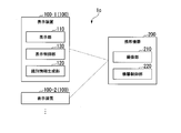
- 6 is a flowchart illustrating an example of an identification number regeneration process in the display device of the first embodiment. It is a block diagram which shows an example of the display system by 2nd Embodiment. It is a block diagram which shows an example of the display part in 2nd Embodiment.
- FIG. 1 is an external view showing an example of a display system 1 according to the first embodiment.
- 2 is a block diagram showing an example of the display system 1 according to the first embodiment.
- the display system 1 includes a plurality of display devices (10-1 to 10-6) and a mobile device 20.
- the display system 1 is a system for performing multi-display in which a plurality of display devices (10-1 to 10-6) are arranged side by side and used, and the display devices (10-1 to 10-6) are operated from the portable device 20. To do.
- the display device 10-1, the display device 10-2, the display device 10-3, the display device 10-4, the display device 10-5, and the display device 10-6 have the same configuration.
- the display device 10 will be described as an arbitrary display device included in the display system 1 or when no particular distinction is made.
- Each of the plurality of display devices 10 displays an identification number pattern indicating an identification number on the display unit 11.
- the identification number is an example of identification information that identifies the display device 10.
- each of the plurality of display devices 10 includes a display unit 11 and a remote control signal receiving unit 14.
- the display unit 11 and the remote control signal receiving unit 14 included in the display device 10-1 are referred to as the display unit 11-1 and the remote control signal receiving unit 14-1, and the display unit 11 and the remote control included in the display device 10-2 are included.
- the signal receiving unit 14 is the display unit 11-2 and the remote control signal receiving unit 14-2.
- the display unit 11 and the remote control signal receiving unit 14 included in the display device 10-3 are referred to as the display unit 11-3 and the remote control signal receiving unit 14-3, and the display unit 11 and the remote control signal receiving unit 14 included in the display device 10-4 are included.
- the display unit 11 and the remote control signal receiving unit 14 included in the display device 10-5 are referred to as the display unit 11-5 and the remote control signal receiving unit 14-5, and the display unit 11 and the remote control signal receiving unit 14 included in the display device 10-6 are included.
- the display unit 11-6 and a remote control signal receiving unit 14-6 are used as a display unit 11-6 and a remote control signal receiving unit 14-6.
- the mobile device 20 is, for example, an electronic device such as a smartphone or a tablet terminal, and functions as a remote control device (remote control device) that operates the plurality of display devices 10.
- the mobile device 20 includes an imaging unit 21 and a remote control signal transmission unit 25.
- the mobile device 20 captures an image including an identification number pattern displayed by the imaging unit 21 on the display units 11 of the plurality of display devices 10, and recognizes each display device 10 based on the identification number pattern included in the captured image. Find the number.
- the mobile device 20 uses the detected identification number of each display device 10 to transmit a remote control signal such as an operation command from the remote control signal transmission unit 25 to operate the plurality of display devices 10.
- a remote control signal such as an operation command from the remote control signal transmission unit 25 to operate the plurality of display devices 10.
- Each display device 10 receives a remote control signal such as an operation command from the remote control signal receiving unit 14, and when the received remote control signal is an operation command for the device itself, executes various processes corresponding to the operation command.
- the display device 10 includes a display unit 11, an identification number generation unit 12, a display control unit 13, a remote control signal reception unit 14, an identification number storage unit 15, and a display pattern generation unit 16.
- the video processing unit 17 and the display switching unit 18 are provided.
- the identification number generation unit 12 (an example of the identification information generation unit) generates an identification number (identification information) for identifying its own device (display device 10) under the control of the display control unit 13.
- the identification number generation unit 12 generates an identification number, for example, in response to an instruction to generate an identification number from the mobile device 20.
- the identification number generation unit 12 stores the generated identification number in the identification number storage unit 15.
- the identification number generation unit 12 regenerates the identification number, for example, when receiving a regeneration instruction for the own device (display device 10) from the mobile device 20.
- the recognition number generation unit 12 regenerates the recognition number excluding the recognition number included in the generation exclusion information.
- the generation exclusion information is a list of identification numbers corresponding to the display devices 10 of which the identification numbers do not overlap among the plurality of display devices 10, and is acquired from the mobile device 20.
- the regeneration instruction includes, for example, the identification number corresponding to the own device, and the identification number generation unit 12 recognizes the identification number included in the regeneration instruction and the identification number stored in the identification number storage unit 15. If and match, the identification number is regenerated.
- the identification number generation unit 12 stores the regenerated identification number in the identification number storage unit 15.
- the identification number storage unit 15 stores the identification number generated by the identification number generation unit 12.
- the display pattern generation unit 16 (an example of a pattern generation unit) generates an identification number pattern which is a display pattern indicating an identification number, under the control of the display control unit 13.
- the display pattern generation unit 16 generates a barcode, which is a one-dimensional code, or a QR code (registered trademark), which is a two-dimensional code, from the identification number stored in the identification number storage unit 15.
- the display pattern generation unit 16 outputs the generated identification number pattern to the display switching unit 18.
- the video processing unit 17 performs resolution conversion from the resolution of the input video to the resolution of the display device 10 and image quality adjustment for the video based on the video signal (input video) input from the outside of the display device 10.
- the video processing unit 17 outputs the video subjected to the resolution conversion and the image quality adjustment to the display switching unit 18.
- the display switching unit 18 switches between the identification number pattern output by the display pattern generation unit 16 and the video output by the video processing unit 17 based on the control of the display control unit 13, and outputs the video to the display unit 11.
- the display unit 11 is, for example, a liquid crystal display, and displays an identification number pattern during an identification number setting process for setting an identification number.
- the display unit 11 also displays various video screens based on the output of the display switching unit 18.
- the detailed configuration of the display unit 11 will be described with reference to FIG.
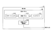
- FIG. 3 is a block diagram showing an example of the display unit 11 in this embodiment.
- the display unit 11 includes a backlight 111, a liquid crystal panel 112, a color filter 113, and a liquid crystal panel drive unit 114.
- the backlight 111, the liquid crystal panel 112, and the color filter 113 correspond to the display panel 30.
- the backlight 111 has, for example, a light emitting diode or an EL (Electro Luminescence) panel, and generates the illumination light of the display unit 11.
- the backlight 111 emits the generated illumination light from the back surface which is the surface opposite to the display surface of the liquid crystal panel 112.
- the liquid crystal panel 112 modulates the brightness of the illumination light emitted from the backlight 111 and illuminates the color filter 113.
- the color filter 113 colors the illumination light whose brightness is modulated via the liquid crystal panel 112 into, for example, three primary colors of light.
- the liquid crystal panel drive unit 114 generates a drive signal for the liquid crystal panel 112 based on the output (display input) of the display switching unit 18, and supplies the drive signal to the liquid crystal panel 112.
- the remote control signal receiving unit 14 (an example of a receiving unit) has, for example, an infrared light receiving element, and receives the operation information transmitted by the mobile device 20.
- the operation information indicates the content of the operation on the display device 10, and the operation information includes, for example, the above-described generation instruction and regeneration instruction, a non-display instruction for stopping the display of the identification number pattern, and the display device 10. It includes operation commands such as various operation instructions.
- the remote control signal receiving unit 14 outputs the received operation information (operation command) to the display control unit 13.
- the display control unit 13 is, for example, a processor including a CPU (Central Processing Unit) and controls the display device 10 in a centralized manner.
- the display control unit 13 causes the display unit 11 to output output information (for example, an identification number pattern) indicating the identification number generated by the identification number generation unit 12.
- output information for example, an identification number pattern
- the display control unit 13 when the display control unit 13 receives an identification number generation instruction via the remote control signal reception unit 14, the display control unit 13 causes the identification number generation unit 12 to generate an identification number and stores the identification number in the identification number storage unit 15. And the display pattern generation unit 16 is caused to generate an identification number pattern indicating an identification number. Then, the display control unit 13 causes the display unit 11 to display the identification number pattern generated by the display pattern generation unit 16. That is, the display control unit 13 causes the display switching unit 18 to switch the video output from the video processing unit 17 to the recognition number pattern output from the display pattern generation unit 16, and displays the recognition number pattern on the display unit 11.
- the display control unit 13 also causes the display unit 11 to output output information indicating the regenerated identification number. That is, the display control unit 13 regenerates the identification number in the identification number generation unit 12 when receiving the instruction to regenerate the identification number for the own device (display device 10) via the remote control signal reception unit 14, for example. Then, the recognition number is stored in the recognition number storage unit 15, and the display pattern generation unit 16 is caused to regenerate the recognition number pattern. Then, the display control unit 13 causes the display unit 11 to display the regenerated identification number pattern via the display switching unit 18.
- the display switching unit 18 instructs the display switching unit 18 to start the video processing unit 17 based on the identification number pattern.
- the image output by the image processing unit 17 is displayed on the display unit 11 by switching to the image output by the image processing unit 17.
- the display control unit 13 executes an operation process corresponding to the operation command.
- the mobile device 20 includes an imaging unit 21, a device control unit 22, a device storage unit 23, a touch screen 24, and a remote control signal transmission unit 25.
- the imaging unit 21 is, for example, a digital camera having an imaging device such as a CCD (Charge Coupled Device) image sensor or a CMOS image sensor, and captures images displayed by the display units 11 of the plurality of display devices 10. That is, the image capturing unit 21 captures an image including the identification number pattern displayed by each display device 10, and outputs the captured image to the device control unit 22.
- CCD Charge Coupled Device
- the device storage unit 23 stores various information used by the mobile device 20.
- the device storage unit 23 includes a dedicated program storage unit 231 and an identification number list storage unit 232.
- the dedicated program storage unit 231 stores a dedicated program for using the display system 1.
- the identification number list storage unit 232 (an example of the identification information list storage unit) stores information about the identification numbers corresponding to the plurality of display devices 10.
- a data example of the identification number list storage unit 232 will be described with reference to FIG.
- FIG. 4 is a diagram showing an example of data in the identification number list storage unit 232 in this embodiment.
- the identification number list storage unit 232 stores “identification number”, “detection coordinate”, and “selected state” in association with each other.
- the “recognition number” indicates the identification number corresponding to each display device 10
- the “detection coordinate” indicates the coordinate on the captured image corresponding to each arrangement of the plurality of display devices 10.
- the “selected state” indicates whether or not each display device 10 is in a selected state for operation.
- the “detection coordinate” of the display device 10 corresponding to the “recognition number” of “XXX1” is “(XXX1, XXXX)”, and the “selected state” is “non-selected”. It is shown that. Also, it is indicated that the “detection coordinates” of the display device 10 corresponding to the “identification number” of “XXX2” is “(XXX2, XXXX)” and the “selected state” is “non-selected”.
- the identification number list storage unit 232 stores, as an identification number list, a set of “identification numbers”, “detection coordinates”, and “selected states” for the number of display devices 10 included in the display system 1.
- the touch screen 24 is, for example, a touch panel having a display function, and includes a mobile device display unit 241 and a touch coordinate detection unit 242.
- the mobile device display unit 241 (an example of an operation display unit) is, for example, a liquid crystal display, and displays an operation screen for operating the plurality of display devices 10.
- the mobile device display unit 241 displays an imaging screen when the imaging unit 21 images the identification numbers of the plurality of display devices 10.
- the touch coordinate detection unit 242 (an example of an operation detection unit) is, for example, a touch panel, and detects a user operation.
- the touch coordinate detection unit 242 is arranged so as to overlap the display surface of the mobile device display unit 241 so that the touch coordinates on the touch screen 24 (on the display surface of the mobile device display unit 241) can be detected.
- the touch coordinate detection unit 242 detects the touch coordinates touched by the user on the touch screen 24 (on the display surface of the mobile device display unit 241).
- the touch coordinate detection unit 242 outputs the detected touch coordinates to the device control unit 22.
- the remote control signal transmission unit 25 includes, for example, an infrared light emitting element, and operation information indicating the content of the operation (for example, the whole of the plurality of display devices 10 or each of the plurality of display devices 10). Operation command). That is, the operation information includes a specific operation command that includes an operation command (for example, an instruction to generate an identification number) that collectively operates all the display devices 10 and an identification number of the display device 10 that is the operation target. An operation command for operating the display device 10 (for example, an instruction to generate an identification number or various operation instructions) is included.
- the device control unit 22 is, for example, a processor including a CPU and controls the mobile device 20 in a centralized manner.
- the device control unit 22 causes the image capturing unit 21 to capture images displayed by the display units 11 of the plurality of display devices 10, for example. Further, the device control unit 22 detects and detects the identification number corresponding to each of the plurality of display devices 10 based on the output information (for example, the identification number pattern) included in the image captured by the imaging unit 21.
- the identification number is associated with each arrangement of the plurality of display devices 10.
- the device control unit 22 also includes an identification number generation instruction unit 221, an identification number detection unit 222, a button control unit 223, and an operation command processing unit 224.
- the identification number generation instruction unit 221, the identification number detection unit 222, the button control unit 223, and the operation command processing unit 224 for example, cause the CPU to execute the dedicated program stored in the dedicated program storage unit 231. Is a functional unit realized by.
- the identification number generation instructing unit 221 transmits an identification number generation instruction for causing the plurality of display devices 10 to generate the identification number and displaying the identification number pattern indicating the identification number on the display unit 11 to the plurality of display devices 10. .. That is, the identification number generation instruction unit 221 causes the remote control signal transmission unit 25 to transmit the identification number generation instruction to all of the plurality of display devices 10.
- the recognition number generation instructing unit 221 instructs the display device 10 corresponding to the overlapping recognition number to reproduce the recognition number. Send a successful instruction. That is, the identification number generation instructing unit 221 causes the remote control signal transmission unit 25 to transmit a regeneration instruction including the duplicated identification number when, for example, the identification numbers stored in the identification number list storage unit 232 overlap. ..
- the recognition number generation instructing unit 221 also excludes generation of a list (list) of recognition numbers corresponding to the display devices 10 whose recognition numbers do not overlap, based on the recognition number list stored in the recognition number list storage unit 232. Extract information.
- the identification number generation instructing unit 221 transmits the extracted generation exclusion information to the display device 10 corresponding to the overlapping identification number. That is, the identification number generation instruction unit 221 causes the remote control signal transmission unit 25 to transmit a regeneration instruction including the generation exclusion information.
- the identification number detection unit 222 detects the identification number corresponding to each of the plurality of display devices 10 based on the identification number pattern included in the image captured by the imaging unit 21, and the detected identification number and the plurality of display devices 10 are included. Correspond with each arrangement of. That is, the identification number detection unit 222 acquires, for example, the image G1 as shown in FIG. 5 from the imaging unit 21, and outputs the identification number corresponding to each of the plurality of display devices 10 based on the identification number pattern included in the image. To detect.
- FIG. 5 is a diagram showing an example of a picked-up image of the identification number pattern in the present embodiment
- an image G1 shown in FIG. 5 is a picked-up image obtained by picking up the plurality of display devices 10 shown in FIG. 1 described above.
- the identification number detection unit 222 associates the detected identification number with the arrangement of each of the plurality of display devices 10 and stores them in the identification number list storage unit 232 as shown in FIG. 4, for example.
- the identification number detection unit 222 sets the “selection state” corresponding to all the identification numbers to “non-selected” and sets the identification number list. It is stored in the storage unit 232.
- the button control unit 223 controls the display of the mobile device display unit 241 and the detection of the operation by the touch coordinate detection unit 242.
- the button control unit 223 displays, for example, a plurality of display units that match the arrangement of the plurality of display devices 10 based on the identification numbers associated with the identification number detection unit 222 and the respective arrangements of the plurality of display devices 10.
- the mobile device display unit 241 displays a selection area for selecting each of the display devices 10. That is, the button control unit 223, based on the identification number list stored in the identification number list storage unit 232, arranges a plurality of display devices 10 and selects the selection buttons, for example, as in the selection button area BT1 shown in FIG.
- the selection button is displayed on the portable device display unit 241 so as to match the arrangement.
- the coordinates of the display area of the selection button and the selection area corresponding to each display device 10 are set based on the “detection coordinates” stored in the identification number list storage unit 232.
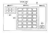
- FIG. 6 is a diagram showing an example of the operation screen of the mobile device 20 in the present embodiment.
- a selection button area BT1 that is an area of a selection button that selects the display device 10
- an operation button area BT2 that is an area of an operation button that specifies various operations
- An end button BT3 which is a control button is included.
- the button control unit 223 causes the mobile device display unit 241 to display the operation screen G2.
- the button control unit 223 executes the operation of selecting the display device 10 corresponding to the selection area by the identification number. That is, when the touch coordinate detection unit 242 selects the selection button (selection region) of the selection button region BT1, the button control unit 223 associates the display device 10 corresponding to the selected selection button with the identification number.
- the “selected state” of the identification number list storage section 232 is changed to “selected”.
- the button control unit 223 processes the operation command corresponding to the selected operation button, which will be described later. To run.
- the button control unit 223 displays the operation screen (for example, the operation screen G2 illustrated in FIG. 6) on the mobile device display unit 241 when the touch button detection unit 242 selects the end button BT3 that is the control button. Stop the display.
- the operation command processing unit 224 causes the button control unit 223 to transmit the operation command corresponding to the detected operation button to the remote control signal transmission unit 25.
- the operation command processing unit 224 searches the recognition number list stored in the recognition number list storage unit 232, for example, and extracts the recognition number whose “selected state” is set to “selected”.
- the operation command processing unit 224 causes the remote control signal transmission unit 25 to transmit the operation command including the extracted identification number and detected by the button control unit 223.
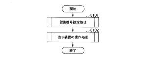
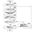
- FIG. 7 is a flowchart showing an example of the operation of the mobile device 20 in this embodiment.
- the mobile device 20 first executes an identification number setting process (step S101).
- the mobile device 20 causes all of the display devices 10 included in the display system 1 to generate an identification number, and causes the display device 10 to display an identification number pattern indicating the generated identification number.
- the mobile device 20 images the identification number pattern displayed on the display device 10 by the imaging unit 21, detects the identification number, and sets the detected identification number. The details of the identification number setting process will be described later with reference to FIG.
- the mobile device 20 executes an operation process of the display device 10 that operates the display device 10 (step S102).
- the details of the operation processing of the display device 10 will be described later with reference to FIG. 9.
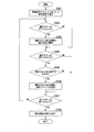
- FIG. 8 is a flowchart showing an example of the identification number setting process in the mobile device 20 of this embodiment.
- the mobile device 20 first instructs the display device 10 to generate an identification number (step S201).
- the identification number generation instruction unit 221 of the device control unit 22 transmits the identification number generation instruction to all the display devices 10 included in the display system 1 via the remote control signal transmission unit 25.
- the mobile device 20 captures an image of the display unit 11 of the display device 10 (step S202). That is, when the display device 10 displays the identification number pattern on the display unit 11, the identification number detection unit 222 of the device control unit 22 causes the imaging unit 21 to capture a captured image including the identification number pattern.
- the identification number detection unit 222 detects the identification number of each display device 10 from the captured image (step S203). That is, the identification number detection unit 222 acquires, for example, a captured image such as the image G1 in FIG. 5 from the imaging unit 21, and the recognition corresponding to each of the plurality of display devices 10 based on the identification number pattern included in the image. Find the number.
- the identification number detection unit 222 stores the list of identification numbers in the identification number list storage unit 232 (step S204).
- the identification number detection unit 222 associates the detected identification number with the arrangement of each of the plurality of display devices 10 and stores them in the identification number list storage unit 232 as shown in FIG. 4, for example.
- the identification number detection unit 222 causes the identification number list storage unit 232 to store the position coordinates (position coordinates of the identification number pattern) of the display device 10 on the captured image corresponding to the identification number as detection coordinates.
- the identification number detection unit 222 determines whether or not the identification numbers overlap (step S205).
- the identification number detection unit 222 refers to the identification number list stored in the identification number list storage unit 232, for example, and determines whether or not the detected identification numbers are duplicated.
- the identification number detection unit 222 advances the process to step S206 when the identification numbers overlap (step S205: YES). In addition, when there is no duplication of the identification numbers (step S205: NO), the identification number detection unit 222 advances the process to step S207.
- step S206 the identification number generation instructing unit 221 instructs the display device 10 having the duplicated identification number to regenerate the identification number. That is, the identification number generation instruction unit 221 causes the remote control signal transmission unit 25 to transmit a regeneration instruction including the identification number corresponding to the display device 10 having the duplicated identification number.
- the recognition number generation instructing unit 221 excludes generation based on the recognition number list stored in the recognition number list storage unit 232, which shows a list (list) of recognition numbers corresponding to the display devices 10 whose recognition numbers do not overlap. Extract information.
- the identification number generation instructing unit 221 transmits the extracted generation exclusion information to the display device 10 corresponding to the overlapping identification number.
- the identification number generation instructing unit 221 returns the processing to step S202.
- step S207 the device control unit 22 instructs the display device 10 not to display the identification number pattern.
- the device control unit 22 transmits an instruction to stop the display of the identification number pattern to all the display devices 10 included in the display system 1 via the remote control signal transmission unit 25.
- the device control unit 22 ends the identification number setting process.
- FIG. 9 is a flowchart showing an example of operation processing of the display device 10 in the mobile device 20 of this embodiment.
- the mobile device 20 first displays an operation screen based on the list of identification numbers (step S301).
- the button control unit 223 of the device control unit 22 causes the mobile device display unit 241 to display, for example, the operation screen G2 shown in FIG. 6 based on the identification number list stored in the identification number list storage unit 232. ..
- the button control unit 223 causes the mobile device display unit 241 to display the arrangement of selection buttons for selecting the display device 10 on the operation screen G2 so as to match the actual arrangement of the display device 10.
- the button control unit 223 determines whether or not the selection button has been pressed (step S302). That is, the button control unit 223 determines whether the selection button (selection region) in the selection button region BT1 illustrated in FIG. 6 is touched by the touch coordinate detection unit 242, for example.
- the button control unit 223 advances the process to step S303. Further, when the selection button is not pressed (step S302: NO), the button control unit 223 advances the process to step S304.
- step S303 the button control unit 223 updates the selection state of the selected display device 10. That is, the button control unit 223 changes the “selected state” of the display device 10 corresponding to the selected selection button to the identification number list storage unit 232 corresponding to the identification number to “selected”.
- the button control unit 223 may perform the toggle operation so that the selection button is in the “non-selected state” when it is pressed again. In this case, the button control unit 223 changes the "selected state" of the identification number list storage unit 232 corresponding to the identification number of the display device 10 corresponding to the selected selection button from "selected" to "non-selected", or , Change from “non-selected” to “selected”.
- step S304 the button control unit 223 determines whether the operation button has been pressed. That is, the button control unit 223 determines whether the operation button in the operation button area BT2 illustrated in FIG. 6 is touched by the touch coordinate detection unit 242, for example.
- step S304: YES the button control unit 223 advances the process to step S305. Further, when the operation button is not pressed (step S304: NO), the button control unit 223 advances the process to step S307.
- step S305 the button control unit 223 determines whether or not there is the selected display device 10. That is, the button control unit 223 refers to, for example, the identification number list stored in the identification number list storage unit 232, and determines whether or not there is an identification number whose selection state is “selected” and selects the selected display device 10. It is determined whether or not there is. If there is the selected display device 10 (step S305: YES), the button control unit 223 advances the process to step S306. In addition, when there is no selected display device 10 (step S305: NO), the button control unit 223 advances the process to step S307.
- step S306 the operation command processing unit 224 of the device control unit 22 transmits the operation command to the selected display device 10.
- the button control unit 223 refers to the recognition number list stored in the recognition number list storage unit 232 and extracts all the recognition numbers whose selection state is “selected”.
- the button control unit 223 sends an operation command including the identification number whose selected state is “selected”, which corresponds to the operation button selected by the button control unit 223, via the remote control signal transmission unit 25. To send.
- the button control unit 223 may transmit operation commands as many as the extracted identification numbers, or may include a plurality of identification numbers in one operation command.
- step S307 the button control unit 223 determines whether or not the end button has been pressed. That is, the button control unit 223 determines whether the end button BT3 illustrated in FIG. 6 is touched by the touch coordinate detection unit 242, for example.
- step S307: YES the button control unit 223 advances the process to step S308. If the end button is not pressed (step S307: NO), the button control unit 223 returns the process to step S302.
- step S308 the button control unit 223 ends the display of the operation screen and ends the operation processing of the display device 10.
- FIG. 10 is a flowchart showing an example of the operation of the display device 10 in this embodiment.
- the display device 10 first determines whether or not a remote control signal has been received (step S401).
- the display control unit 13 of the display device 10 determines whether or not a remote control signal such as an operation command is received from the mobile device 20 via the remote control signal receiving unit 14.
- the display control unit 13 receives the remote control signal (step S401: YES)
- the process proceeds to step S402.
- the remote control signal is not received (step S401: NO)
- the display control unit 13 returns the process to step S401.
- step S402 the display control unit 13 executes branch processing according to the received remote control signal.
- step S402 instruction to generate the identification number
- step S403 the instruction to regenerate the identification number
- step S402 instruction to regenerate the identification number
- step S402 non-display instruction of the identification number pattern
- step S405 the display control unit 13 advances the process to step S406.
- step S403 the display control unit 13 executes an identification number generation process.
- the display control unit 13 generates the identification number of its own device and causes the display unit 11 to display the identification number pattern indicating the generated identification number. The details of the generation processing of the identification number will be described later with reference to FIG. After the processing of step S403, the display control unit 13 returns the processing to step S401.
- step S404 the display control unit 13 executes a process of regenerating the identification number.
- the display control unit 13 regenerates the identification number of the own device and causes the display unit 11 to display the identification number pattern indicating the regenerated identification number. Details of the identification number regeneration processing will be described later with reference to FIG. After the processing of step S404, the display control unit 13 returns the processing to step S401.
- step S405 the display control unit 13 stops displaying the identification number pattern. That is, the display control unit 13 causes the display switching unit 18 to switch the recognition number pattern to the video output by the video processing unit 17, and causes the display unit 11 to display the video output by the video processing unit 17. After the processing of step S405, the display control unit 13 returns the processing to step S401.
- step S406 the display control unit 13 determines whether the identification number included in the operation command and the identification number of the own device match. That is, the display control unit 13 determines whether the identification number stored in the identification number storage unit 15 matches the identification number included in the operation command. If the identification numbers match (step S406: YES), the display control unit 13 advances the process to step S407. If the identification numbers do not match (step S406: NO), the display control unit 13 returns the process to step S401.
- step S407 the display control unit 13 executes the operation command. That is, the display control unit 13 executes various operation processes according to the content of the operation command. After the processing of step S407, the display control unit 13 returns the processing to step S401.
- FIG. 11 is a flowchart showing an example of an identification number generation process in the display device 10 of this embodiment.
- the display device 10 first generates an identification number (step S501). That is, the display control unit 13 of the display device 10 causes the identification number generation unit 12 to generate the identification number.
- the identification number generation unit 12 may generate, as the identification number, a random number (or a number based on the random number) generated by using a random number generator (not shown).
- the identification number generation unit 12 prepares a plurality of lists indicating the generation order of the identification numbers, selects a list to be used based on the random number generated by the random number generator, and selects the selected list.
- the identification numbers may be generated by sequentially allocating the identification numbers in. In this way, the identification number generation unit 12 may generate the identification number based on the random number.
- the identification number generation unit 12 also stores the generated identification number in the identification number storage unit 15.
- the display device 10 generates an identification number pattern (step S502). That is, the display control unit 13 causes the identification number generation unit 12 to generate an identification number.
- the display pattern generation unit 16 generates an identification number pattern such as a barcode which is a one-dimensional code or a QR code (registered trademark) which is a two-dimensional code from the identification numbers stored in the identification number storage unit 15.
- the display pattern generation unit 16 outputs the generated identification number pattern to the display switching unit 18.
- the display device 10 displays the identification number pattern (step S503). That is, the display control unit 13 causes the display switching unit 18 to switch the video output from the video processing unit 17 to the recognition number pattern output from the display pattern generation unit 16, and displays the recognition number pattern on the display unit 11. Let After the processing of step S503, the display control unit 13 ends the identification number generation processing.
- FIG. 12 is a flowchart showing an example of the identification number regeneration processing in the display device 10 of the present embodiment.
- the display device 10 determines whether the identification number included in the regeneration instruction and the identification number of the self device match (step S601). That is, the display control unit 13 of the display device 10 determines whether the identification number stored in the identification number storage unit 15 matches the identification number included in the regeneration instruction. If the identification numbers match (step S601: YES), the display control unit 13 advances the process to step S602. Further, when the identification numbers do not match (step S601: NO), the display control unit 13 ends the identification number regeneration processing.
- step S602 the display device 10 regenerates the identification number.
- the display control unit 13 causes the identification number generation unit 12 to regenerate the identification number, so that the identification number generation unit 12 regenerates the identification number.
- the identification number generation unit 12 determines whether or not the generated identification number is included in the generation exclusion information (step S603).
- the identification number generation unit 12 determines whether or not the generation exclusion information received from the mobile device 20 includes the regenerated identification number. If the generated identification number is included in the generation exclusion information (step S603: YES), the identification number generation unit 12 returns the process to step S602. If the generated identification number is not included in the generation exclusion information (step S603: NO), the identification number generation unit 12 advances the process to step S604.
- step S605 Since the subsequent processing of steps S604 and S605 is similar to the processing of steps S502 and S503 shown in FIG. 11 described above, the description thereof is omitted here.
- step S605 the display control unit 13 ends the identification number regeneration processing.
- the display system 1 includes the plurality of display devices 10 and the mobile device 20 that operates the plurality of display devices 10.
- Each of the plurality of display devices 10 includes an identification number generation unit 12 (identification information generation unit) and a display control unit 13.
- the identification number generation unit 12 generates an identification number (identification information) for identifying its own device (display device 10).
- the display control unit 13 causes the display unit 11 to output the recognition number pattern (output information) indicating the recognition number generated by the recognition number generation unit 12.
- the mobile device 20 also includes an imaging unit 21 and a device control unit 22.
- the image capturing unit 21 captures images displayed by the display units 11 of the plurality of display devices 10.
- the device control unit 22 detects an identification number corresponding to each of the plurality of display devices 10 based on the identification number pattern included in the image captured by the imaging unit 21, and detects the detected identification number and the plurality of display devices 10. Correspond with each arrangement.
- each of the plurality of display devices 10 can independently generate and set the identification number (identification information).
- the identification number is set in advance. No need for complicated operations.
- the display system 1 according to the present embodiment outputs the identification number pattern indicating the identification number generated by each of the plurality of display devices 10 from the display unit 11, so that the mobile device 20 displays the identification number and the plurality of displays.
- the respective arrangements of the device 10 can be easily associated with each other.
- all that is required is for the user to direct the image capturing unit 21 of the mobile device 20 so that the identification number patterns displayed on all the display devices 10 included in the display system 1 can be captured. Different identification numbers can be set on the display device 10. Therefore, the display system 1 according to the present embodiment can improve convenience, for example, when performing a multi-display in which a plurality of display devices 10 are arranged and used.
- the mobile device 20 includes a mobile device display unit 241 (operation display unit) that displays an operation screen for operating the plurality of display devices 10, and a touch coordinate detection unit 242 (operation that detects a user operation). And a touch screen 24 having a detector.
- the device control unit 22 selects each of the plurality of display devices 10 displayed so as to match the arrangement of the plurality of display devices 10, based on the associated identification number and the respective arrangement of the plurality of display devices 10.
- a selection button selection area
- the device control unit 22 executes the operation of selecting the display device 10 corresponding to the selection button by the identification number.
- the user operates the selection button arranged so as to match the actual arrangement of the display device 10 displayed on the mobile device display unit 241 of the mobile device 20.
- the display device 10 can be easily operated by selecting the display device 10 desired. Therefore, the display system 1 according to the present embodiment can further improve convenience.
- the device control unit 22 transmits a regeneration instruction for instructing regeneration of the identification numbers to the display device 10 corresponding to the duplicated identification numbers. ..
- the identification number generation unit 12 regenerates the identification number when receiving a regeneration instruction for the own device (display device 10). Then, the display control unit 13 causes the display unit 11 to output an identification number pattern indicating the regenerated identification number.
- the display system 1 causes the display devices 10 corresponding to the duplicated identification numbers to regenerate the identification numbers when the identification numbers are duplicated. Can be easily set.
- the device control unit 22 when the device control unit 22 transmits the regeneration instruction to the display device 10 corresponding to the overlapping recognition number, the device control unit 22 displays a display in which the recognition numbers are not duplicated among the plurality of display devices 10. Generation exclusion information indicating a list of identification numbers corresponding to the device 10 is transmitted.
- the recognition number generation unit 12 receives the regeneration instruction for the own device (display device 10), the recognition number generation unit 12 regenerates the recognition number excluding the recognition number included in the generation exclusion information.
- the display device 10 uses the generation exclusion information to exclude the identification number set in another display device 10 and regenerates the identification number, so that the recognition is performed efficiently.
- the number can be regenerated.
- each of the plurality of display devices 10 includes a display pattern generation unit 16 (pattern generation unit) that generates, as output information, a display pattern indicating a recognition number (for example, a recognition number pattern).
- the display control unit 13 causes the display unit 11 to display the display pattern generated by the display pattern generation unit 16.
- the device control unit 22 detects an identification number corresponding to each of the plurality of display devices 10 based on a display pattern (for example, an identification number pattern) included in the image captured by the imaging unit 21. Accordingly, in the display system 1 according to the present embodiment, the mobile device 20 can easily detect the identification number by the imaging unit 21 capturing an image including the display pattern (for example, the identification number pattern).
- the display unit 11 has a display panel 30 that displays an image.
- the display system 1 according to the present embodiment improves convenience when using the display device 10 including the display panel 30, for example, when performing multiple display in which a plurality of display devices 10 are arranged and used. Can be made
- the mobile device 20 includes the remote control signal transmission unit 25 (transmission unit) that transmits operation information indicating the content of the operation to all of the plurality of display devices 10 or each of the plurality of display devices 10.
- the remote control signal transmission unit 25 transmission unit
- Each of the plurality of display devices 10 includes a remote control signal reception unit 14 (reception unit) that receives the operation information transmitted by the mobile device 20.
- the mobile device 20 appropriately operates the plurality of display devices 10 by using the remote control signal transmission unit 25 (transmission unit) and the remote control signal reception unit 14 (reception unit). You can
- the identification number generation unit 12 generates the identification number based on the random number.
- the display system 1 according to the present embodiment can efficiently generate the identification number while reducing the duplication of the identification number.
- the mobile device 20 stores the identification number and the selection state information (for example, “selection state”) indicating whether or not the display device 10 corresponding to the identification number is in the selected state.
- An identification number list storage unit 232 identification information list storage unit which is associated and stored is provided.
- the device control unit 22 corresponds to the recognition number in which the selection state information (for example, “selection state”) is selected (for example, “selection”) among the recognition numbers stored in the recognition number list storage unit 232.
- the operation information is transmitted to the display device 10.
- the display system 1 brings a plurality of selection state information (for example, “selection state”) stored in the identification number list storage unit 232 into a selected state (for example, “selection”).
- selection state for example, “selection state”
- control method is a control method of the display system 1 including a plurality of display devices 10 and a mobile device 20 that operates the plurality of display devices 10, and includes an identification information generation step and a display control step. And an imaging step and a device control step.
- identification information generating step each of the plurality of display devices 10 generates an identification number (identification information) that identifies itself.
- display control step each of the plurality of display devices 10 causes the display unit 11 to output the identification number pattern (output information) indicating the identification number generated in the identification information generation step.
- the mobile device 20 images the images displayed by the display units 11 of the plurality of display devices 10.
- the mobile device 20 detects the identification number corresponding to each of the plurality of display devices 10 based on the output information included in the image captured in the imaging step, and the detected identification number and the plurality of identification numbers are detected.
- the respective arrangements of the display device 10 are associated with each other.
- the control method according to the present embodiment has the same effects as the above-described display system 1 and can improve convenience.
- FIG. 13 is a block diagram showing an example of the display system 1a according to the present embodiment.
- the display system 1a includes a plurality of display devices 10a and a mobile device 20. Note that, in FIG. 13, as in the case of FIG. 2 described above, one of the plurality of display devices 10a is described and the description of the other display device 10a is omitted. Further, in this figure, the same components as those in FIG. 2 are designated by the same reference numerals, and the description thereof will be omitted.
- the display device 10a includes a display unit 11a, an identification number generation unit 12, a display control unit 13, a remote control signal reception unit 14, an identification number storage unit 15, a display pattern generation unit 16, a video processing unit 17, and a video processing unit 17.
- the display switching unit 18 is provided.
- the display device 10a is the same as that of the first embodiment except that the display unit 11 of the first embodiment is replaced with the display unit 11a.
- the display unit 11a is, for example, a projector and projects an image on the screen SC (an example of a display target).
- the display unit 11a displays the identification number pattern, for example, in the identification number setting process of setting the identification number.
- the display unit 11a displays screens of various images on the screen SC based on the output of the display switching unit 18.
- the detailed configuration of the display unit 11a will be described with reference to FIG.
- FIG. 14 is a block diagram showing an example of the display unit 11a in the present embodiment.
- the display unit 11a includes a light source unit 111a, a spatial light modulator 112a, a projection lens unit 113a, and a spatial light modulator driver 114a.
- the light source unit 111a, the spatial light modulator 112a, and the projection lens unit 113a correspond to the projection unit 30a.
- the light source unit 111a generates illumination light for the projector.
- the light source unit 111a irradiates the spatial light modulator 112a with the generated illumination light.
- the spatial light modulator 112a modulates the illumination light emitted from the light source unit 111a and irradiates the projection lens unit 113a with the modulated illumination light.
- a liquid crystal panel that is a transmissive device, a reflective liquid crystal panel that is a reflective device, a DMD (Digital Micromirror Device), or the like is used.
- the projection lens unit 113a projects the illumination light modulated via the spatial light modulator 112a onto the screen SC, for example.
- the screen SC is an example of a display target.
- the spatial light modulator drive unit 114a generates a drive signal for the spatial light modulator 112a based on the output (display input) of the display switching unit 18 and supplies the drive signal to the spatial light modulator 112a.
- the operation of the display system 1a according to the present embodiment is the same as that of the first embodiment except that the display unit 11 is replaced with the display unit 11a, and thus the description thereof is omitted here.
- the display system 1a includes the plurality of display devices 10a and the mobile device 20 that operates the plurality of display devices 10a.
- the display control unit 13 causes the display unit 11a to output the identification number pattern (output information) indicating the identification number generated by the identification number generation unit 12.
- the image capturing unit 21 captures images displayed by the display units 11a of the plurality of display devices 10a.
- the device control unit 22 detects an identification number corresponding to each of the plurality of display devices 10a based on the identification number pattern included in the image captured by the imaging unit 21, and detects the detected identification number and the plurality of display devices 10a. Correspond with each arrangement.
- the display system 1a according to the present embodiment has the same effects as those of the above-described first embodiment and can improve convenience.
- the display unit 11a has a projection unit 30a that projects an image on the screen SC (display target).
- the display system 1a according to the present embodiment improves convenience when using the display device 10a including the projection unit 30a, for example, when performing multi-display in which a plurality of display devices 10a are arranged and used. Can be made
- FIG. 15 is a block diagram showing an example of the display system 1b according to this embodiment.
- the display system 1b includes a plurality of display devices 10b and a mobile device 20a. Note that, in FIG. 15, as in the case of FIG. 2 described above, one of the plurality of display devices 10b is described and the description of the other display device 10b is omitted. Further, in this figure, the same components as those in FIG. 2 are designated by the same reference numerals, and the description thereof will be omitted.
- the display device 10b includes a display unit 11b, an identification number generation unit 12, a display control unit 13a, a remote control signal reception unit 14, an identification number storage unit 15, a video processing unit 17, and a modulation signal generation unit 19.
- Prepare The display device 10b includes a modulation signal generation unit 19 instead of the display pattern generation unit 16 and the display switching unit 18, and the display control unit 13 and the display unit 11 are replaced by the display control unit 13a and the display unit 11b. Except for the points, it is similar to the first embodiment.
- the modulation signal generation unit 19 generates a modulation signal indicating an identification number as output information under the control of the display control unit 13a.
- the modulation signal is a signal obtained by coding the identification number, and is a signal for modulating the brightness of the backlight 111 at a frequency higher than the frame frequency of the image.
- the modulation signal generation unit 19 generates a modulation signal from the identification number stored in the identification number storage unit 15.
- the modulation signal generation unit 19 outputs the generated modulation signal to the display unit 11b.
- the display unit 11b is, for example, a liquid crystal display, and modulates the brightness of the backlight 111 with a modulation signal indicating the identification number during the identification number setting process for setting the identification number.
- the display unit 11b displays various video screens based on the output of the video processing unit 17.
- the detailed configuration of the display unit 11b will be described with reference to FIG.
- FIG. 16 is a block diagram showing an example of the display unit 11b in this embodiment.
- the display unit 11b includes a backlight 111, a liquid crystal panel 112, a color filter 113, a liquid crystal panel drive unit 114, and a backlight modulation unit 115.
- the backlight 111, the liquid crystal panel 112, and the color filter 113 correspond to the display panel 30.
- the backlight modulator 115 modulates the brightness of the backlight 111 based on the modulation signal supplied from the modulation signal generator 19. Since the brightness of the backlight 111 is modulated at a frequency higher than the frame frequency of the image, human eyes cannot visually recognize the brightness change.
- the display control unit 13a is, for example, a processor including a CPU and controls the display device 10b in an integrated manner.
- the display control unit 13a causes the display unit 11 to output output information (for example, brightness modulation) indicating the identification number generated by the identification number generation unit 12. That is, the display control unit 13a modulates the luminance of the display unit 11b based on the modulation signal generated by the modulation signal generation unit 19 and outputs the modulated luminance.
- output information for example, brightness modulation
- the display control unit 13a causes the modulation signal generation unit 19 to generate a modulation signal indicating the identification number, and causes the backlight modulation unit 115 of the display unit 11b to modulate the brightness of the backlight 111 based on the modulation signal. Except for the points, the other processes are the same as those of the display control unit 13 of the first embodiment. Therefore, description of the other processes of the display control unit 13a is omitted here.
- the mobile device 20a includes an imaging unit 21, a device control unit 22a, a device storage unit 23, a touch screen 24, and a remote control signal transmission unit 25.
- the device control unit 22a is, for example, a processor including a CPU and the like, and integrally controls the mobile device 20a.
- the device control unit 22a causes the imaging unit 21 to capture an image displayed by the display unit 11b of the plurality of display devices 10b, for example. Further, the device control unit 22a detects and detects the identification number corresponding to each of the plurality of display devices 10b based on the output information (for example, the brightness modulation) included in the image captured by the image capturing unit 21.
- the identification number is associated with each arrangement of the plurality of display devices 10b.
- the device control unit 22a includes an identification number generation instruction unit 221, an identification number detection unit 222a, a button control unit 223, and an operation command processing unit 224.
- the identification number generation instructing unit 221, the identification number detecting unit 222a, the button control unit 223, and the operation command processing unit 224 for example, cause the CPU to execute the dedicated program stored in the dedicated program storage unit 231. Is a functional unit realized by.
- the identification number detection unit 222a detects the identification number corresponding to each of the plurality of display devices 10b based on the identification number pattern included in the image captured by the imaging unit 21, and the detected identification number and the plurality of display devices 10b. Correspond with each arrangement of.
- the identification number detection unit 222a detects the change in the brightness of the image and demodulates the change in the brightness (modulation of the brightness) to detect the identification number corresponding to each of the plurality of display devices 10b.
- the identification number detecting unit 222a associates the detected identification number with the arrangement of each of the plurality of display devices 10b, and stores them in the identification number list storage unit 232 as shown in FIG. 4, for example.
- Other configurations and processes of the mobile device 20a are the same as those of the mobile device 20 of the first embodiment, and thus the description thereof is omitted here.
- the display system 1b includes the plurality of display devices 10b and the mobile device 20a that operates the plurality of display devices 10b.
- the display control unit 13a causes the display unit 11b to output the brightness modulation (output information) indicating the identification number generated by the identification number generation unit 12.
- the image capturing unit 21 captures images displayed by the display units 11b of the plurality of display devices 10b.
- the device control unit 22a detects the identification number corresponding to each of the plurality of display devices 10b based on the brightness modulation included in the image captured by the imaging unit 21, and the detected identification number and the plurality of display devices 10b. Correspond with each arrangement.
- the display system 1b according to the present embodiment has the same effects as those of the above-described first embodiment and can improve convenience.
- each of the plurality of display devices 10b includes a modulation signal generation unit 19 that generates a modulation signal indicating an identification number as output information.
- the display control unit 13a modulates the brightness of the display unit 11b based on the modulation signal generated by the modulation signal generation unit 19 and outputs the modulated brightness.
- the device control unit 22a detects the identification number corresponding to each of the plurality of display devices 10b based on the modulated brightness (for example, change in brightness) of the display unit 11b included in the image captured by the imaging unit 21. To do. Accordingly, in the display system 1b according to the present embodiment, the mobile device 20a can easily detect the identification number by the imaging unit 21 capturing the change in the brightness of the image.
- the modulation signal generated by the modulation signal generation unit 19 has a frequency higher than the frame frequency of the display of the display unit 11b.
- the identification number can be easily set without being visually recognized by the user (that is, without being aware that the identification number is set).
- FIG. 17 is a block diagram showing an example of the display system 1c according to this embodiment.
- the display system 1c includes a plurality of display devices 100 (100-1, 100-2, ...) And a mobile device 200.
- the display system 1c is a system for performing multi-display in which a plurality of display devices 100 are arranged and used, and the display device 100 is operated from the mobile device 200.
- each of the display device 100-1, the display device 100-2, ... Has the same configuration, and represents any display device included in the display system 1c, or does not particularly distinguish. Will be described as the display device 100.
- Each of the plurality of display devices 100 includes a display unit 110, an identification information generation unit 120, and a display control unit 130.
- the identification information generation unit 120 generates identification information (for example, an identification number) that identifies itself.
- the display control unit 130 causes the display unit 110 to output output information indicating the identification information generated by the identification information generation unit 120.
- the output information is, for example, a display pattern indicating the identification information, a brightness modulation indicating the identification information, or the like.
- the mobile device 200 operates a plurality of display devices 100.
- the mobile device 200 includes an imaging unit 210 and a device control unit 220.
- the image capturing unit 210 captures images displayed by the display units 110 of the plurality of display devices 100.
- the device control unit 220 detects the recognition information corresponding to each of the plurality of display devices 100 based on the output information included in the image captured by the imaging unit 210, and the detected recognition information and each of the plurality of display devices 100. Correlate with the arrangement of.
- each of the plurality of display devices 100 can individually generate and set identification information, and for example, a complicated operation such as setting recognition information in advance. Don't need Further, the display system 1c according to the present embodiment outputs the output information indicating the recognition information generated by each of the plurality of display devices 100 from the display unit 110, so that the mobile device 200 can recognize the recognition information and the plurality of display devices. It is possible to easily associate each of the 100 arrangements. Therefore, the display system 1c according to the present embodiment can improve convenience.
- the present invention is not limited to the above-mentioned embodiment, and can be modified within the scope of the present invention.
- the mobile device 20 (20a, 200) is an electronic device such as a smartphone or a tablet terminal has been described, but the present invention is not limited to this. It may be.
- the example in which the coordinates on the captured image are used as the “detection coordinates” stored in the identification number list storage unit 232 has been described, but it corresponds to each arrangement of the plurality of display devices 10.
- the coordinates on the touch screen 24 may be the coordinates of the display area of the selection button corresponding to each display device 10 and the selection area.
- the display device 10 (10b) is not limited to the liquid crystal display including the backlight 111.
- the backlight 111 the liquid crystal panel 112, and the color filter.
- a display using an organic EL or LED (Light Emitting Diode) which is a self-luminous device may be used.
- Each of the components included in the display system 1 (1a to 1c) described above has a computer system inside. Then, a program for realizing the functions of the respective constituents of the above-described display system 1 (1a to 1c) is recorded in a computer-readable recording medium, and the program recorded in this recording medium is read by the computer system. Alternatively, the processing in each configuration included in the display system 1 (1a to 1c) described above may be performed.
- “reading and executing a program recorded in a recording medium on a computer system” includes installing the program in the computer system.
- the “computer system” mentioned here includes an OS and hardware such as peripheral devices.
- the “computer system” may include a plurality of computer devices connected via a network including a communication line such as the Internet, WAN, LAN, and a dedicated line.
- the "computer-readable recording medium” refers to a portable medium such as a flexible disk, a magneto-optical disk, a ROM, a CD-ROM, or a storage device such as a hard disk built in a computer system.
- the recording medium storing the program may be a non-transitory recording medium such as a CD-ROM.
- the recording medium includes a recording medium provided inside or outside accessible from the distribution server for distributing the program.
- the programs are divided into a plurality of programs and downloaded at different timings, and then combined in the respective configurations of the display system 1 (1a to 1c) and the distribution server for distributing each of the divided programs is different.
- the "computer-readable recording medium” holds a program for a certain period of time, such as a volatile memory (RAM) inside a computer system that serves as a server or a client when the program is transmitted via a network. It also includes things.
- the program may be for realizing a part of the functions described above. Further, it may be a so-called difference file (difference program) that can realize the above-mentioned functions in combination with a program already recorded in the computer system.
- LSI Large Scale Integration
- Each of the functions described above may be individually implemented as a processor, or part or all of the functions may be integrated and implemented as a processor.
- the method of circuit integration is not limited to LSI, and may be realized by a dedicated circuit or a general-purpose processor. Further, in the case where an integrated circuit technology that replaces the LSI appears due to the progress of semiconductor technology, an integrated circuit according to the technology may be used.
Landscapes
- Engineering & Computer Science (AREA)
- Theoretical Computer Science (AREA)
- Physics & Mathematics (AREA)
- General Physics & Mathematics (AREA)
- Human Computer Interaction (AREA)
- General Engineering & Computer Science (AREA)
- Crystallography & Structural Chemistry (AREA)
- Chemical & Material Sciences (AREA)
- Computer Hardware Design (AREA)
- Signal Processing (AREA)
- Computer Networks & Wireless Communication (AREA)
- Controls And Circuits For Display Device (AREA)
- Selective Calling Equipment (AREA)
Abstract
La présente invention porte sur un système d'affichage qui comprend une pluralité de dispositifs d'affichage et un dispositif mobile pour actionner la pluralité de dispositifs d'affichage ; la pluralité de dispositifs d'affichage comprennent chacun une unité de génération d'informations d'identification qui génère des informations d'identification servant à identifier le dispositif d'affichage respectif, et une unité de commande d'affichage qui amène une unité d'affichage à fournir des informations de sortie représentant les informations d'identification générées par l'unité de génération d'informations d'identification ; et le dispositif mobile comprend une unité d'imagerie servant à capturer des images présentées par les unités d'affichage de la pluralité de dispositifs d'affichage, et une unité de commande de dispositif qui détecte des informations d'identification correspondant à chacun des dispositifs d'affichage sur la base des informations de sortie incluses dans les images capturées par l'unité d'imagerie et associe les informations d'identification détectées à la position de chacun des dispositifs d'affichage.
Priority Applications (2)
| Application Number | Priority Date | Filing Date | Title |
|---|---|---|---|
| PCT/JP2018/040841 WO2020090110A1 (fr) | 2018-11-02 | 2018-11-02 | Système d'affichage et procédé de commande |
| US17/222,918 US11294614B2 (en) | 2018-11-02 | 2021-04-05 | Display system and control method |
Applications Claiming Priority (1)
| Application Number | Priority Date | Filing Date | Title |
|---|---|---|---|
| PCT/JP2018/040841 WO2020090110A1 (fr) | 2018-11-02 | 2018-11-02 | Système d'affichage et procédé de commande |
Related Child Applications (1)
| Application Number | Title | Priority Date | Filing Date |
|---|---|---|---|
| US17/222,918 Continuation US11294614B2 (en) | 2018-11-02 | 2021-04-05 | Display system and control method |
Publications (1)
| Publication Number | Publication Date |
|---|---|
| WO2020090110A1 true WO2020090110A1 (fr) | 2020-05-07 |
Family
ID=70463634
Family Applications (1)
| Application Number | Title | Priority Date | Filing Date |
|---|---|---|---|
| PCT/JP2018/040841 Ceased WO2020090110A1 (fr) | 2018-11-02 | 2018-11-02 | Système d'affichage et procédé de commande |
Country Status (2)
| Country | Link |
|---|---|
| US (1) | US11294614B2 (fr) |
| WO (1) | WO2020090110A1 (fr) |
Families Citing this family (3)
| Publication number | Priority date | Publication date | Assignee | Title |
|---|---|---|---|---|
| CA3188115A1 (fr) * | 2021-08-31 | 2023-02-28 | Unefi Inc. | Determination d'article dote d'un ecran au moyen d'indices |
| US12513352B2 (en) * | 2024-05-22 | 2025-12-30 | Roku, Inc. | Remote control system for multiple multimedia devices |
| US20250365463A1 (en) * | 2024-05-22 | 2025-11-27 | Roku, Inc. | Remote control system for multiple multimedia devices |
Citations (5)
| Publication number | Priority date | Publication date | Assignee | Title |
|---|---|---|---|---|
| WO2008152807A1 (fr) * | 2007-06-13 | 2008-12-18 | Panasonic Corporation | Procédé d'élimination de chevauchement d'adresses mac, système de gestion de dispositif réseau, serveur et dispositif d'informations |
| WO2013186835A1 (fr) * | 2012-06-11 | 2013-12-19 | Necディスプレイソリューションズ株式会社 | Système d'affichage multi-écrans, dispositif d'affichage, appareil de réglage id, et procédé de réglage id |
| JP2016085435A (ja) * | 2014-10-29 | 2016-05-19 | 株式会社リコー | 画像処理システム |
| JP2017116689A (ja) * | 2015-12-24 | 2017-06-29 | セイコーエプソン株式会社 | 画像投写システム、画像投写システムの制御方法、端末装置、及び、プログラム |
| JP2018152663A (ja) * | 2017-03-10 | 2018-09-27 | 株式会社リコー | 画像処理装置、表示システム、画像処理装置の制御方法及びプログラム |
Family Cites Families (3)
| Publication number | Priority date | Publication date | Assignee | Title |
|---|---|---|---|---|
| CA2711449C (fr) * | 2008-01-07 | 2016-09-06 | Smart Technologies Ulc | Procede et appareil pour afficher des donnees video provenant de plusieurs ordinateurs sources dans un systeme d'ordinateur a plusieurs ecrans |
| KR101890624B1 (ko) * | 2012-04-12 | 2018-08-22 | 엘지전자 주식회사 | 터치패드를 구비한 리모트 컨트롤러 및 그 제어 방법 |
| US10003485B2 (en) * | 2016-01-25 | 2018-06-19 | Lumic Technology Inc. | Systems of synchronizing lighting effect control signals and patterns for controlling interactive lighting effect devices |
-
2018
- 2018-11-02 WO PCT/JP2018/040841 patent/WO2020090110A1/fr not_active Ceased
-
2021
- 2021-04-05 US US17/222,918 patent/US11294614B2/en active Active
Patent Citations (5)
| Publication number | Priority date | Publication date | Assignee | Title |
|---|---|---|---|---|
| WO2008152807A1 (fr) * | 2007-06-13 | 2008-12-18 | Panasonic Corporation | Procédé d'élimination de chevauchement d'adresses mac, système de gestion de dispositif réseau, serveur et dispositif d'informations |
| WO2013186835A1 (fr) * | 2012-06-11 | 2013-12-19 | Necディスプレイソリューションズ株式会社 | Système d'affichage multi-écrans, dispositif d'affichage, appareil de réglage id, et procédé de réglage id |
| JP2016085435A (ja) * | 2014-10-29 | 2016-05-19 | 株式会社リコー | 画像処理システム |
| JP2017116689A (ja) * | 2015-12-24 | 2017-06-29 | セイコーエプソン株式会社 | 画像投写システム、画像投写システムの制御方法、端末装置、及び、プログラム |
| JP2018152663A (ja) * | 2017-03-10 | 2018-09-27 | 株式会社リコー | 画像処理装置、表示システム、画像処理装置の制御方法及びプログラム |
Also Published As
| Publication number | Publication date |
|---|---|
| US20210224016A1 (en) | 2021-07-22 |
| US11294614B2 (en) | 2022-04-05 |
Similar Documents
| Publication | Publication Date | Title |
|---|---|---|
| CN107797364B (zh) | 显示系统、显示装置及其控制方法、控制器以及记录介质 | |
| RU2617932C2 (ru) | Интерактивная система, способ управления для интерактивной системы и проектор | |
| JP6398248B2 (ja) | 位置検出システム、及び、位置検出システムの制御方法 | |
| US9665335B2 (en) | Projector, display device, display system, and control method of display device | |
| CN102722289B (zh) | 图像供给装置、图像显示系统和图像供给装置的控制方法 | |
| US9904414B2 (en) | Display device, and method of controlling display device | |
| JP2015510671A (ja) | 光源のリモートコントロール | |
| US20150208050A1 (en) | Projector, display apparatus, and control method of projector | |
| WO2008041605A1 (fr) | Appareil de projection, support d'enregistrement comportant un programme enregistré en lui, procédé de projection et système de projection | |
| US11294614B2 (en) | Display system and control method | |
| CN110018778B (zh) | 通信设备、显示设备及其控制方法、存储介质和显示系统 | |
| JP2017182110A (ja) | 表示システム、表示装置、情報処理装置及び情報処理方法 | |
| JP6562124B2 (ja) | 位置検出システム、及び、位置検出システムの制御方法 | |
| US9830723B2 (en) | Both-direction display method and both-direction display apparatus | |
| US20160283087A1 (en) | Display apparatus, display system, control method for display apparatus, and computer program | |
| JP2017182109A (ja) | 表示システム、情報処理装置、プロジェクター及び情報処理方法 | |
| US20150279336A1 (en) | Bidirectional display method and bidirectional display device | |
| JP2013061380A (ja) | 表示制御装置、画像表示装置、表示システム、表示システムの制御方法、及び、プログラム | |
| US20220311980A1 (en) | Display method and display system | |
| RU2665296C2 (ru) | Способ двунаправленного отображения и устройство двунаправленного отображения | |
| CN103295387A (zh) | 一种电子设备、投影遥控器及其实现方法 | |
| CN113194302B (zh) | 智能显示设备及开机控制方法 | |
| JP6690272B2 (ja) | 位置検出システム、自発光指示体、および固有情報取得方法 | |
| JP2016184268A (ja) | 表示装置、表示システム、及び、表示装置の制御方法 | |
| JP2020086103A (ja) | 表示システム、及び制御方法 |
Legal Events
| Date | Code | Title | Description |
|---|---|---|---|
| 121 | Ep: the epo has been informed by wipo that ep was designated in this application |
Ref document number: 18938225 Country of ref document: EP Kind code of ref document: A1 |
|
| NENP | Non-entry into the national phase |
Ref country code: DE |
|
| 122 | Ep: pct application non-entry in european phase |
Ref document number: 18938225 Country of ref document: EP Kind code of ref document: A1 |
|
| NENP | Non-entry into the national phase |
Ref country code: JP |