WO2020090133A1 - Dispositif et procédé pour assembler un corps non magnétique - Google Patents
Dispositif et procédé pour assembler un corps non magnétique Download PDFInfo
- Publication number
- WO2020090133A1 WO2020090133A1 PCT/JP2019/009488 JP2019009488W WO2020090133A1 WO 2020090133 A1 WO2020090133 A1 WO 2020090133A1 JP 2019009488 W JP2019009488 W JP 2019009488W WO 2020090133 A1 WO2020090133 A1 WO 2020090133A1
- Authority
- WO
- WIPO (PCT)
- Prior art keywords
- bonding
- joining
- magnetic
- joined
- magnet
- Prior art date
- Legal status (The legal status is an assumption and is not a legal conclusion. Google has not performed a legal analysis and makes no representation as to the accuracy of the status listed.)
- Ceased
Links
Images



Classifications
-
- B—PERFORMING OPERATIONS; TRANSPORTING
- B29—WORKING OF PLASTICS; WORKING OF SUBSTANCES IN A PLASTIC STATE IN GENERAL
- B29C—SHAPING OR JOINING OF PLASTICS; SHAPING OF MATERIAL IN A PLASTIC STATE, NOT OTHERWISE PROVIDED FOR; AFTER-TREATMENT OF THE SHAPED PRODUCTS, e.g. REPAIRING
- B29C65/00—Joining or sealing of preformed parts, e.g. welding of plastics materials; Apparatus therefor
- B29C65/48—Joining or sealing of preformed parts, e.g. welding of plastics materials; Apparatus therefor using adhesives, i.e. using supplementary joining material; solvent bonding
- B29C65/52—Joining or sealing of preformed parts, e.g. welding of plastics materials; Apparatus therefor using adhesives, i.e. using supplementary joining material; solvent bonding characterised by the way of applying the adhesive
- B29C65/54—Joining or sealing of preformed parts, e.g. welding of plastics materials; Apparatus therefor using adhesives, i.e. using supplementary joining material; solvent bonding characterised by the way of applying the adhesive between pre-assembled parts
Definitions
- the present invention relates to a non-magnetic material joining apparatus and method for joining non-magnetic materials.
- a fiber reinforced composite material for example, CFRP (carbon fiber reinforced plastic), has a lower density than metal materials such as iron and aluminum, but also has excellent mechanical properties, high specific strength, and is light and strong. Therefore, in recent years, it has been used as an alternative structural member for aluminum alloys in aircraft, small boats, automobiles, and the like.
- CFRP carbon fiber reinforced plastic
- FRP fiber-reinforced composite material
- Patent Document 1 has the following problems. (1) When a thermosetting adhesive is used as the adhesive, it is necessary to heat the adhesive to a temperature (for example, 100 to 130 ° C.) necessary for thermosetting while applying a pressing force to the joining area. As a result, it is necessary to hold the pressure jig until the adhesive is cured, and the bonding area is limited to a narrow range (range depending on the size of the pressure jig), so that the width or length is large. It was difficult to apply it to the joint area. (2) When the width or length of the joining range is large, it is necessary to increase the size of the pressing jig or prepare a large number of pressing jigs.
- a temperature for example, 100 to 130 ° C.
- an object of the present invention is to provide a non-magnetic material bonding apparatus and method that can bond non-magnetic materials to each other even when the width or length of the bonding range is large (for example, 1 m or more) and that can be manually attached and detached. To do.
- a non-magnetic material bonding apparatus for bonding a non-magnetic material to be bonded and a bonding material, A pressure-receiving member located in close contact with the back surface of the material to be bonded in a bonding range where the material to be bonded and the material to be bonded are overlapped via an adhesive; A pressure roller that has an outer peripheral surface that comes into close contact with the surface of the bonding material and that can roll along the surface of the bonding material; A magnetic force generator for generating a pressing force on the sandwiching portion sandwiched between the outer peripheral surface and the pressure receiving member, There is provided a non-magnetic material joining device, comprising: a heating device that heats the holding portion.
- a nonmagnetic joining method using the above nonmagnetic joining apparatus The material to be joined and the material to be joined are superposed with an adhesive, Positioning the pressure receiving member in close contact with the back surface of the material to be bonded in the overlapping bonding range, Abutting the outer peripheral surface of the pressure roller to the bonding material surface located in the bonding range, By the magnetic force generator, a pressing force is generated in the holding portion, By the heating device, the clamping unit is heated, At the same time, a non-magnetic material bonding method is provided in which the pressure roller is rolled along the bonding material surface in the bonding range.
- the magnetic force generator can generate a pressing force by a magnetic force between the outer peripheral surface of the pressure roller and the sandwiching portion sandwiched by the pressure receiving member.
- the heating device can heat the sandwiching portion sandwiched between the pressure roller and the pressure receiving member.
- the pressure roller has an outer peripheral surface that abuts on the surface of the bonding material and is rollable along the surface of the bonding material, rolling the pressure roller over the entire bonding range results in the entire bonding range. Can be evenly pressurized and heated. Therefore, even when the width or the length of the bonding range is large (for example, 1 m or more), the nonmagnetic materials can be bonded to each other.
- a single non-magnetic material joining device can join a joining range having a large width or length, it is not necessary to increase the size of the pressure roller, and the weight of the device can be reduced. Can be installed and removed manually.
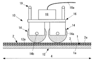
- FIG. 1 is a front view of a first embodiment of a non-magnetic material bonding apparatus according to the present invention.
- 1 is a side view of a first embodiment of a non-magnetic material joining device according to the present invention. It is a front view of 2nd Embodiment of the non-magnetic material joining apparatus by this invention.
- FIG. 3 is a view on arrow AA of FIG. 2.
- It is a front view of 3rd Embodiment of the non-magnetic substance joining apparatus by this invention.
- It is a 1st perspective view which shows the joining method using the non-magnetic substance joining apparatus by this invention.
- It is a front view which shows the joining method using the non-magnetic body joining apparatus by this invention.
- FIG. 1A is a front view of a first embodiment of a non-magnetic material bonding apparatus 10 according to the present invention
- FIG. 1B is a side view of the first embodiment.
- non-magnetic material means a material that is not magnetized by a magnetic field and therefore is not affected by the magnetic field.
- Non-magnetic materials include fiber reinforced composite materials (FRP) and aluminum alloys.
- the non-magnetic material joining apparatus 10 of the present invention is an apparatus for joining the non-magnetic material to be joined 1 and the joining material 2, and includes a pressure receiving member 12 and a pressure roller 14.
- the material to be joined 1 and the material to be joined 2 are preferably CFRP (carbon fiber reinforced composite material), but may be other FRP (fiber reinforced composite material), aluminum alloy, or the like.
- the material to be joined 1 and the material to be joined 2 are flat plates, and their ends are overlapped with each other with an adhesive 3 interposed therebetween.
- the materials to be bonded 1 and the material to be bonded 2 are not limited to flat plates and may be arcuate surfaces or other shapes as long as they can be superposed with the adhesive 3.
- the pressure receiving member 12 is fixed in close contact with the back surface 1a of the joined material 1 in the joining area 4 where the joined material 1 and the joined material 2 are overlapped.
- the pressure receiving member 12 is preferably a ferromagnetic material or a magnet (electromagnet or permanent magnet) that generates an attraction force by a magnetic force between the pressure receiving member 12 and the pressure roller 14 (described later).
- Magnetic material means a substance that is strongly magnetized by a magnetic field and becomes a magnet at that point, and remains magnetized even when the magnetic field is removed.
- the material of the pressure receiving member 12 may be, for example, iron, cobalt, nickel or their alloys, ferrite, or the like.
- the pressure receiving member 12 is a plate member that is in close contact with and fixed to the back surface 1a of the material 1 to be welded over the entire bonding range 4, and has a contact surface 12a that is in close contact with the back surface 1a.
- any means for fixing the pressure receiving member 12 to the back surface 1a of the material 1 to be joined, any means (for example, A fixing jig, a temporary fixing metal fitting, an adhesive tape, an adhesive, etc.) can be applied. It is preferable that these fixing means can return to the original state after the joined material 1 and the joined material 2 are joined.
- the adhesive 3 is preferably a heat curing type one-component epoxy resin type or a one-component acrylic resin type, but may be a curing agent mixed type two-component epoxy resin type or two-component silicone rubber type.
- the adhesive 3 may be a thermoplastic type. Further, the form of the adhesive 3 is preferably sheet-like, but may be liquid. For example, the thermoplastic film may be melted and adhered (welded).
- the pressure roller 14 has an outer peripheral surface 14a that comes into close contact with the surface of the bonding material 2 (hereinafter, the bonding material surface 2a), and is configured to be able to roll along the bonding material surface 2a.
- the pressure roller 14 has a cylindrical shape, and its outer peripheral surface 14a has a cylindrical shape.
- the outer peripheral surface 14a is not limited to a cylindrical shape as long as it can be brought into close contact with the bonding material surface 2a, and may have another shape.
- the pressure roller 14 has therein a magnetic force generator 15a and a heating device 15b.
- the magnetic force generator 15a or the heating device 15b may be installed outside the pressure roller 14.
- the heating device 15b is preferably a dielectric heating device that selectively heats the resin, for example.
- the dielectric heating device is installed inside the upper controller 18, for example.
- the magnetic force generator 15a generates a predetermined pressing force on the sandwiching portion 5 sandwiched between the outer peripheral surface 14a and the pressure receiving member 12.
- the “predetermined pressing force” may be, for example, 0.05 MPa to 1.0 MPa.
- the magnetic force generator 15a is preferably an electromagnet, but may be a permanent magnet.
- a pair of pressure rollers 14 are provided coaxially, and the magnetic poles of the outer peripheral surface 14a are set to be opposite (N and S).
- a strong magnetic field can be generated between the magnetic poles (N and S) on the outer peripheral surface 14a and the pressure receiving member 12, and a pressing force corresponding to the attraction force by the magnetic force can be applied to the holding portion 5.
- the magnetic poles on the outer peripheral surface 14a are not limited to this example, and all may be N poles or S poles.
- the heating device 15b heats the holding portion 5 held between the outer peripheral surface 14a and the pressure receiving member 12 to a predetermined temperature.
- the “predetermined temperature” is preferably the temperature required for curing the adhesive 3 (for example, 100 to 120 ° C.).
- the non-magnetic material joining device 10 includes a preheating device (not shown), and when the entire joining range 4 is a thermosetting type, it is uniformly heated to a temperature lower than the curing temperature of the adhesive 3.
- the non-magnetic material bonding apparatus 10 includes four pressure rollers 14. Further, in this figure, the non-magnetic material bonding apparatus 10 includes a roller support base 16 that rotatably supports two sets (four) of pressure rollers 14 that are paired by two.
- the rotating shafts 14b of the two sets of pressure rollers 14 are positioned in parallel to each other, the outer peripheral surfaces 14a of the two sets of pressure rollers 14 simultaneously contact the bonding material surface 2a, and in the same direction along the bonding material surface 2a. You can roll at the same time.
- an upper controller 18 is attached to the roller support base 16.
- a power supply line 18a is connected to the upper controller 18 from the outside, and power is supplied to the magnetic force generator 15a (in the case of an electromagnet) and the heating device 15b via the upper controller 18.
- the magnetic force generator 15a is a permanent magnet
- the upper controller 18 supplies electric power only to the heating device 15b.
- the roller support base 16 is further provided with a handle 19.
- the operator moves the roller support 16 along the bonding material surface 2a during the bonding work, and this movement causes the outer peripheral surface 14a of the pressure roller 14 to contact the bonding material surface 2a and to perform bonding. It is adapted to roll along the material surface 2a. With this configuration, even when the width or length of the joining range 4 is large (for example, when the width or the length is 1 m or more), the outer peripheral surface 14a of the pressure roller 14 can be rolled over the entire joining range 4. ..
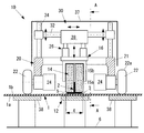
- FIG. 2 is a front view of the second embodiment of the non-magnetic material bonding apparatus 10 according to the present invention
- FIG. 3 is a view taken along the line AA of FIG.
- the material to be joined 1 is a flat plate, but may be an arc surface or another shape.
- the bonding material 2 is a long member having an inverted T-shaped cross section, but the cross-sectional shape may be L-shaped, H-shaped, U-shaped, or the like.
- the length of the long member is, for example, 5 to 6 m, but may be other than that.
- the pressure receiving member 12 is similar to that of the first embodiment, and is fixed in close contact with the back surface 1a of the material 1 to be joined.
- the pressure roller 14 is provided with only one set (two) in which two pairs are provided, but it may be provided with a single set or two sets (four) or more.
- the roller support 16 is similar to that of the first embodiment, but the handle 19 is omitted.
- the non-magnetic material bonding apparatus 10 further includes an upper carriage 20.
- the above-described upper controller 18 is attached to the upper carriage 20.
- the upper carriage 20 is configured to be movable along the surface of the material to be welded 1 or the material to be welded 2 across the welding range 4. Further, the pressure roller 14 is attached to the upper carriage 20 so as to abut on the bonding material surface 2a.
- the upper trolley 20 is in contact with the surface of the material to be welded 1 or the material to be welded 2 (the material to be welded 1 in this example), and a plurality of (four in this example) upper wheels 22 that can roll along this surface.
- An upper drive device 24 that rotationally drives at least one of the upper wheels 22.
- the contact surface 22a of the upper wheel 22 has an arc shape in this example, so that even if the material 1 to be bonded is other than a flat plate (for example, an arc surface or another shape), it surely contacts the surface 1b of the material to be bonded. It has become.
- the upper drive device 24 may be, for example, an electric motor with a speed reducer.
- the upper carriage 20 is moved along the surface 1b of the material to be welded, and in conjunction with this movement, the outer peripheral surface 14a is brought into close contact with the surface 2a of the material to be welded. As it is, the pressure roller 14 can be rolled along the bonding material surface 2a.
- the magnetic force generator 15a when the magnetic force generator 15a is installed outside the pressure roller 14, it is preferable that the magnetic force generator 15a be built in the upper wheel 22 and the support member 38 be made of a ferromagnetic material, for example.
- the upper carriage 20 further includes an upper vibration absorbing device 26 that absorbs vibration of the pressure roller 14 (particularly vertical vibration).
- the upper vibration absorber 26 is composed of, for example, a damper, a pneumatic cylinder, a compression spring, or an elastic member, and is sandwiched between the roller support base 16 and the position holding base 28 in this example. With this configuration, even when the outer surface 14a of the pressure roller 14 comes into contact with the bonding material surface 2a when the upper carriage 20 moves, there is unevenness (or unevenness) on the surface of the position holding table 28 without affecting the position. The vibration of the roller 14 can be absorbed.
- the upper carriage 20 further includes an upper position correction device 30 that corrects the position of the pressure roller 14 with respect to the material 1 to be bonded or the material 2 to be bonded (material 1 to be bonded in this example).
- the upper position correcting device 30 supports a horizontal guide 32 that movably supports the position holding base 28 described above in the width direction (left and right direction in FIG. 2), and moves the horizontal guide 32 in the vertical direction in FIG. And a vertical guide 34 that supports the vertical guide 34.
- the vertical guide 34 is fixed to the main body 21 of the upper carriage 20. Further, the position holding table 28 can be moved in the width direction and the vertical direction in the drawing by an actuator (not shown).
- the relative position (for example, the height) of the pressure roller 14 with respect to the upper wheel 22 can be appropriately corrected by the upper position correction device 30, and the pressure roller 14 can be brought into close contact with the surface of the bonding material 2. .. Further, even during the joining, the position holding base 28 can be moved by the upper position correcting device 30 and the position of the pressure roller 14 can be corrected at any time via the upper vibration absorbing device 26 and the roller supporting base 16. ..
- the upper carriage 20 further includes an upper camera 36 that captures a position of the pressure roller 14 with respect to the bonding material 2.
- the upper camera 36 is a digital camera or a digital video camera, and transmits a captured image by wireless or wired to the operator of the apparatus. While observing this image, the position of the pressure roller 14 can be corrected.
- You can In FIG. 2, 37 is an upper cover that covers the upper part of the upper carriage 20.
- the upper controller 18 supplies electric power to the magnetic force generator 15a and the heating device 15b described above, and also supplies electric power to the upper drive device 24, the upper position correcting device 30, and the upper camera 36. , And control these. This control may be remote control by an operator or autonomous control by the upper controller 18.
- the non-magnetic material joining device 10 further includes a pair of support members 38.
- the pair of support members 38 are a pair of parallel plate materials, and are in close contact with the back surface of the joined material 1 or the joined material 2 (joined material 1 in this example) facing the upper wheel 22. It is fixed. Further, the support member 38 is preferably fixed to the pressure receiving member 12 or the external fixing portion (the fixed support surface 6 in this example).
- the load of the upper carriage 20 acting on the material to be welded 1 or the material to be welded 2 (the material to be welded 1 in this example) via the upper wheel 22 is applied to the pressure receiving member 12 or the external fixing portion via the support member 38. It is possible to prevent the deformation of the material 1 or the material 2 to be bonded.
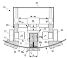
- FIG. 4 is a front view of the third embodiment of the non-magnetic material bonding apparatus 10 according to the present invention.
- the material to be welded 1 is a circular arc surface, and the case where the bonding material 2 is bonded to the inner surface of the circular arc surface is shown.
- the contact surface 12 a of the pressure receiving member 12 is formed in the same arcuate surface as the outer surface of the bonding material 2.
- the upper surface of the support member 38 is also formed in the same arcuate surface as the outer surface of the bonding material 2.
- the non-magnetic material joining apparatus 10 includes a wheel support plate 40 that faces the upper wheel 22 and is closely attached to and fixed to the surface of the material 1 or the material 2 to be joined and supports the upper wheel 22.
- the wheel support plate 40 is a magnet (electromagnet or permanent magnet)
- the support member 38 is a ferromagnetic material or a magnet (electromagnet or permanent magnet) that generates an attraction force by magnetic force between the wheel support plate 40 and the wheel support plate 40.
- a strong magnetic field is generated between the wheel support plate 40 and the support member 38, and the wheel support plate 40 and the support member 38 are brought into close contact with the surface of the joined material 1 or the joining material 2 by the attraction force by the magnetic force. Can be fixed.
- the upper surface of the wheel support plate 40 is formed in a shape (for example, horizontal) that supports the upper wheel 22. Further, it is preferable to provide a guide 42 for guiding the upper wheel 22 on the upper surface of the wheel support plate 40. With this configuration, the upper wheel 22 can be guided along the guide 42. Other configurations are similar to those of the second embodiment.
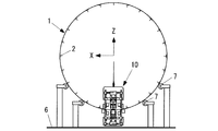
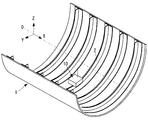
- FIG. 5A is a first perspective view showing a joining method using the non-magnetic body joining apparatus 10 according to the present invention
- FIG. 5B is a front view thereof.
- the material to be joined 1 has a hollow cylindrical shape.
- the direction of the central axis O of the material to be welded 1 is defined as the Y direction
- the horizontal direction orthogonal to the Y direction is defined as the X direction
- the upward direction orthogonal to the Y direction is defined as the Z direction.
- the bonding material 2 is a long member having an inverted T-shaped cross section, extends in the Y direction, and is bonded to the inner inner surface of the material 1 to be bonded.
- a plurality of (24 in this example) bonding materials 2 are circumferentially spaced about the central axis O in this example.
- the material 1 to be joined is supported by a plurality of support rollers 7 so as to be rotatable about a central axis O.
- the non-magnetic material joining apparatus 10 joins the joining material 2 located at the innermost bottom end of the joining material 1 and located at the bottom end thereof to the joining material 1.
- FIG. 5C is a second perspective view showing a joining method using the non-magnetic body joining apparatus 10 according to the present invention.
- the non-magnetic material bonding apparatus 10 may be used to bond the bonding material 2 in the circumferential direction of the material to be bonded 1.
- the non-magnetic material bonding apparatus 10 moves in the circumferential direction to bond the bonding material 2 to the material to be bonded 1.
- the non-magnetic material bonding apparatus 10 may not move, but the material 1 to be bonded may be moved in the circumferential direction.
- Other configurations are the same as those in FIGS. 5A and 5B.
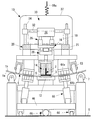
- FIG. 6 is a front view of the fourth embodiment of the non-magnetic material bonding apparatus 10 according to the present invention.
- the contact surface 22a of the upper wheel 22 is formed as a flat surface or an arc surface that is in close contact with the surface 1b of the material 1 to be joined.
- the upper carriage 20 and members associated therewith are the same as in FIG.
- the pressure receiving member 12 is a pressure receiving roller 44 that faces the pressure roller 14 and is in close contact with the back surface 1 a of the material 1 to be joined.
- the pressure receiving roller 44 is a cylindrical member, and can freely roll around its central axis. Other configurations are the same as those of the pressure receiving member 12 of the first to third embodiments.
- the non-magnetic material joining device 10 further includes a lower carriage 46.
- bogie 46 is comprised so that it can move along the back surface of the to-be-bonded material 1 or the to-be-bonded material 2 (to-be-bonded material 1 in this example) straddling the welding range 4.
- the pressure receiving member 12 (pressure receiving roller 44 in this example) is attached to the lower carriage 46 so as to contact the back surface 1 a of the material 1 to be joined.
- the lower carriage 46 is synchronously controlled with the upper carriage 20 so that the pressure receiving member 12 (pressure receiving roller 44) moves while facing the pressure roller 14. This control may be remote control by an operator or autonomous control by the upper controller 18 and the lower controller 60.
- the lower carriage 46 includes a plurality of lower wheels 48 and a lower drive device 50.
- the plurality of lower wheels 48 are configured to come into contact with the back surface 1a of the material 1 to be joined and to be rollable.
- the position of the lower wheel 48 is preferably a position facing the upper wheel 22.
- one of the upper wheel 22 and the lower wheel 48 is a magnet (electromagnet or permanent magnet) and the other is a ferromagnetic material.
- both the upper wheel 22 and the lower wheel 48 may be magnets that generate a magnetic attraction force.
- Other configurations of the lower wheel 48 are similar to those of the upper wheel 22.
- the lower drive device 50 rotationally drives at least one of the lower wheels 48.
- Other configurations of the lower drive device 50 are similar to those of the upper drive device 24.
- the non-magnetic material joining device 10 further includes a lower vibration absorbing device 52 that absorbs the vibration of the pressure receiving roller 44.
- the structure and function of the lower vibration absorber 52 are similar to those of the upper vibration absorber 26.
- the non-magnetic material joining device 10 further includes a lower position correction device 54, a lower camera 56, a lower cover 58, and a lower controller 60. These components and functions are similar to those of the upper position correction device 30, the upper camera 36, the upper cover 37, and the upper controller 18.
- the plate-shaped pressure receiving member 12 is longer than 1 m without being fixed to the back surface 1a of the joined material 1 over the entire joining range 4.
- the material 1 to be bonded and the bonding material 2 can be bonded in the bonding range 4.
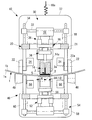
- FIG. 7 is a front view of the fifth embodiment of the non-magnetic material joining device 10 according to the present invention.
- the lower carriage 46 includes a plurality of lower wheels 48A that can roll by abutting on the back surface 1a of the material 1 to be welded, and a plurality of lower wheels 48B that can roll by abutting the lower fixed support surface 6.
- the fixed support surface 6 is, for example, a floor surface.
- the lower wheel 48A is similar to the lower wheel 48 of the fourth embodiment, but need not be a magnet or a ferromagnetic material, and may be made of another material such as rubber or plastic.
- the lower wheel 48A can freely roll without being driven, and the lower drive device 50 rotationally drives the lower wheel 48B.
- the non-magnetic material joining device 10 further includes a roller elevating device 62.
- the roller elevating / lowering device 62 is, for example, a direct-acting pneumatic cylinder or an electric cylinder, and has a function of abutting and pressing the pressure receiving roller 44 (pressure receiving member 12) and the lower wheel 48A against the back surface 1a of the workpiece 1.
- Other configurations are similar to those of the fourth embodiment shown in FIG.
- the plate-shaped pressure receiving member 12 is not fixed to the back surface 1a of the material 1 to be welded over the entire surface of the welding range 4, but each is made of a non-magnetic material.
- the to-be-joined material 1 and the joining material 2 can be joined.
- the lower wheel 48B has a plurality of lower wheels 48B that can be brought into contact with the lower fixed support surface 6 to roll, the entire weight of the lower carriage 46 can be supported by the lower wheel 48B, and the pressure receiving member 12 and the lower wheel 48A can be supported.
- the back surface 1a of the material 1 to be joined can be stably abutted.
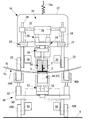
- FIG. 8 is a front view of the sixth embodiment of the non-magnetic material bonding apparatus 10 according to the present invention.
- 63 is a support roller
- 64a and 64b are magnets
- 65 is a magnet lifting device
- 66 is a linear guide
- 68 is a linear drive mechanism.
- the linear drive mechanism 68 is, for example, a drive motor, a ball screw, a rack and pinion, or the like.
- the material 1 to be joined is supported by a plurality of support rollers 7 so as to be rotatable about a central axis O (see FIG. 5A). Further, the upper carriage 20 is supported on the material 1 to be joined by the support roller 63. Further, the upper drive device 24 in FIGS. 7 and 8 is omitted, and the support roller 63 is adapted to freely roll around its axis.
- the magnetic force generator 15a includes an upper magnet 64a and a lower magnet 64b.
- the upper magnet 64a and the lower magnet 64b are electromagnets or permanent magnets.
- the upper magnet 64a is fixed to the upper carriage 20 and is located close to the upper surface of the material 1 to be welded.
- the lower magnet 64b is fixed to the lower carriage 46 via the magnet lifting device 65, and is located close to the lower surface of the workpiece 1.
- the upper magnet 64a and the lower magnet 64b are opposed to each other with the material 1 to be bonded therebetween, and generate an attractive force by a magnetic force therebetween.
- a cushioning material may be sandwiched between the upper magnet 64a or the lower magnet 64b and the material 1 to be bonded.
- the lower carriage 46 is guided by the linear guide 66 so as to be horizontally movable in the length direction of the bonding material 2, and is driven in the length direction of the bonding material 2 by the linear drive mechanism 68.
- the pressure receiving member 12 is fixed to the upper portion of the lower carriage 46.
- the pressure receiving member 12 is located in close contact with the lower surface of the material to be welded 1 and moves along the lower surface of the material to be welded 1.
- the magnet raising / lowering device 65 is fixed to the lower carriage 46, moves the position of the lower magnet 64b up and down, and controls the pressing force generated by the upper magnet 64a and the lower magnet 64b.
- the magnet lifting device 65 is, for example, an electric linear motion cylinder.
- the lower magnet 64b may be composed of a plurality of magnets, and a part of the lower magnet 64b may be moved up and down to control the attraction force. With this configuration, a pressing force corresponding to the attraction force due to the magnetic force can be applied to the holding portion 5. Other configurations are similar to those of the fifth embodiment of FIG. 7.
- the plate-shaped pressure receiving member 12 is not fixed to the back surface 1a of the material 1 to be welded over the entire surface of the welding range 4, but each is made of a non-magnetic material.
- the to-be-joined material 1 and the joining material 2 can be joined.
- the upper carriage 20 moves following the movement of the lower carriage 46 due to the magnetic forces of the upper magnet 64a and the lower magnet 64b, the upper drive device 24 in FIGS. 7 and 8 can be omitted.
- the nonmagnetic material bonding method according to the present invention is a method using the above-described nonmagnetic material bonding apparatus 10.
- the non-magnetic material joining method of the present invention includes a superposing step S1, a positioning step S2, an abutting step S3, and a joining step S4.
- the material 1 to be bonded and the material 2 to be bonded are superposed with the adhesive 3 interposed therebetween.
- the pressure receiving member 12 made of a ferromagnetic material is positioned in close contact with the back surface 1a of the material 1 to be bonded in the overlapping bonding area 4.
- the outer peripheral surface 14a of the pressure roller 14 is brought into contact with the bonding material surface 2a located in the bonding range 4.
- the joined material 1 and the joining material 2 are joined.
- the magnetic force generator 15a generates a pressing force on the sandwiching portion 5, and the heating device 15b heats the sandwiching portion 5.
- the pressure roller 14 is moved along the surface of the joining material 2 in the joining range 4. Roll it.
- the width or the length of the joining range 4 is large, for example, when the width or the length is 1 m or more, in the joining step S4, the pressure roller 14 is rolled in the length direction with respect to the joining range 4 in the width direction. It is also preferable to move it.
- a non-destructive inspection device for example, an ultrasonic sensor
- an ultrasonic flaw test is performed on the bonded portion after bonding, and there is no bonding failure (peeling or void). Is preferably inspected.
- the magnetic force generator 15a can generate a pressing force by a magnetic force between the outer peripheral surface 14a of the pressure roller 14 and the sandwiching portion 5 sandwiched between the pressure receiving members 12. Further, the heating device 15b can heat the sandwiching portion 5 sandwiched between the pressure roller 14 and the pressure receiving member 12.
- the pressure roller 14 since the pressure roller 14 has the outer peripheral surface 14a that abuts on the bonding material surface 2a and can roll along the bonding material surface 2a, by rolling the pressure roller 14 over the entire bonding range 4.
- the entire joining range 4 can be uniformly pressed and heated. Therefore, even when the width or length of the bonding range 4 is large (for example, 1 m or more), the fiber-reinforced composite materials can be bonded to each other.
- one non-magnetic material joining device 10 can join the joining range 4 having a large width or length, it is not necessary to upsize the pressure roller 14 and the weight of the device can be reduced. It can be installed and removed manually.
Landscapes
- Engineering & Computer Science (AREA)
- Mechanical Engineering (AREA)
- Lining Or Joining Of Plastics Or The Like (AREA)
- Pressure Welding/Diffusion-Bonding (AREA)
Abstract
La présente invention est pourvue d'un élément de réception de pression (12) (rouleau de réception de pression (44)), d'un rouleau de pression (14), d'un générateur de force magnétique (15a), et d'un dispositif de chauffage (15b). Le rouleau de réception de pression (44) est positionné en contact étroit avec la surface arrière (1a) d'un matériau (1) à assembler constitué d'un corps non magnétique, dans une plage de jonction (4) dans laquelle le matériau (1) à assembler et un matériau de jonction (2) sont chacun superposés l'un sur l'autre par l'intermédiaire d'un adhésif (3). Le rouleau de pression (14) a une surface circonférentielle externe (14a) destinée à venir en contact étroit avec la surface du matériau de jonction (2), et est conçu de façon à pouvoir rouler le long d'une surface de matériau de jonction (2a). Le générateur de force magnétique (15a) génère une force de pression sur une partie prise en sandwich (5) prise en sandwich par la surface circonférentielle externe (14a) et l'élément de réception de pression (12). Le dispositif de chauffage (15b) chauffe la partie prise en sandwich (5).
Priority Applications (1)
| Application Number | Priority Date | Filing Date | Title |
|---|---|---|---|
| JP2019529289A JP6768958B1 (ja) | 2018-11-01 | 2019-03-08 | 非磁性体接合装置と方法 |
Applications Claiming Priority (2)
| Application Number | Priority Date | Filing Date | Title |
|---|---|---|---|
| JP2018206321 | 2018-11-01 | ||
| JP2018-206321 | 2018-11-01 |
Publications (1)
| Publication Number | Publication Date |
|---|---|
| WO2020090133A1 true WO2020090133A1 (fr) | 2020-05-07 |
Family
ID=70462559
Family Applications (1)
| Application Number | Title | Priority Date | Filing Date |
|---|---|---|---|
| PCT/JP2019/009488 Ceased WO2020090133A1 (fr) | 2018-11-01 | 2019-03-08 | Dispositif et procédé pour assembler un corps non magnétique |
Country Status (2)
| Country | Link |
|---|---|
| JP (1) | JP6768958B1 (fr) |
| WO (1) | WO2020090133A1 (fr) |
Families Citing this family (3)
| Publication number | Priority date | Publication date | Assignee | Title |
|---|---|---|---|---|
| CN116900723B (zh) * | 2023-07-07 | 2025-12-16 | 南京钢铁股份有限公司 | 一种适用于高锰无磁钢的修磨轧制工艺 |
| KR102664611B1 (ko) * | 2023-08-10 | 2024-05-10 | 주식회사 선테크 | 초순수 배관 모듈 제작방법 |
| CN117565413B (zh) * | 2024-01-16 | 2024-03-19 | 四川聚诚达环保科技有限公司 | 一种玄武岩增强塑料化粪池热熔连接装置及方法 |
Citations (5)
| Publication number | Priority date | Publication date | Assignee | Title |
|---|---|---|---|---|
| JPS57135123A (en) * | 1981-02-12 | 1982-08-20 | Automation Industrielle Sa | Continuous manufacture of endless variable type tube and device used for said method |
| JPH1034749A (ja) * | 1996-07-25 | 1998-02-10 | Mitsubishi Heavy Ind Ltd | 接着塗装装置 |
| JP2007253347A (ja) * | 2006-03-20 | 2007-10-04 | Ricoh Co Ltd | 接合部材製造方法、無端状接合ベルト、定着ユニット、中間転写ユニット、画像形成装置、及び、シート接合装置 |
| US20170173864A1 (en) * | 2015-12-21 | 2017-06-22 | Airbus Operations Gmbh | Welding system |
| JP2018517597A (ja) * | 2015-06-05 | 2018-07-05 | ピーピージー コーティングス ヨーロッパ ベーヴェー | 大きな表面を積層するシステムおよび方法 |
-
2019
- 2019-03-08 JP JP2019529289A patent/JP6768958B1/ja active Active
- 2019-03-08 WO PCT/JP2019/009488 patent/WO2020090133A1/fr not_active Ceased
Patent Citations (5)
| Publication number | Priority date | Publication date | Assignee | Title |
|---|---|---|---|---|
| JPS57135123A (en) * | 1981-02-12 | 1982-08-20 | Automation Industrielle Sa | Continuous manufacture of endless variable type tube and device used for said method |
| JPH1034749A (ja) * | 1996-07-25 | 1998-02-10 | Mitsubishi Heavy Ind Ltd | 接着塗装装置 |
| JP2007253347A (ja) * | 2006-03-20 | 2007-10-04 | Ricoh Co Ltd | 接合部材製造方法、無端状接合ベルト、定着ユニット、中間転写ユニット、画像形成装置、及び、シート接合装置 |
| JP2018517597A (ja) * | 2015-06-05 | 2018-07-05 | ピーピージー コーティングス ヨーロッパ ベーヴェー | 大きな表面を積層するシステムおよび方法 |
| US20170173864A1 (en) * | 2015-12-21 | 2017-06-22 | Airbus Operations Gmbh | Welding system |
Also Published As
| Publication number | Publication date |
|---|---|
| JP6768958B1 (ja) | 2020-10-14 |
| JPWO2020090133A1 (ja) | 2021-02-15 |
Similar Documents
| Publication | Publication Date | Title |
|---|---|---|
| JP6768958B1 (ja) | 非磁性体接合装置と方法 | |
| CA2830672C (fr) | Appareil et procede de soudage par induction thermoplastique | |
| JP5616050B2 (ja) | 複合構造部材を連結する方法及び装置と、該方法及び装置によって作製された構造部材 | |
| US20170190445A1 (en) | Apparatuses and methods for manipulating curved sheets | |
| CN114713983B (zh) | 一种汽车门环激光拼焊钢板的自动拼装夹具及操作方法 | |
| CN110961772B (zh) | 接合装置以及接合方法 | |
| US7896994B2 (en) | Ultrasonic assembly method | |
| CN110831745A (zh) | 接合系统及接合方法 | |
| TWI790046B (zh) | 曲面塗膠裝置 | |
| CN102248746B (zh) | 位置保持装置 | |
| Khirade et al. | Magnetic wall climbing devices—a review | |
| EP4212314A1 (fr) | Procédé et système de soudage de panneaux thermoplastiques | |
| JP2019141942A (ja) | 枠体組立方法、枠体組立装置及び枠体 | |
| CN110002009B (zh) | 一种被动柔顺组件及在轨补加接口装置 | |
| JP6878335B2 (ja) | シート巻き付け装置 | |
| JP2018176244A (ja) | 管接合装置及び管接合方法 | |
| KR101795256B1 (ko) | 차체부품 결합장치 | |
| CN223114362U (zh) | 一种超声波焊接治具 | |
| US11919253B2 (en) | Welding assembly and method using separately actuatable rams | |
| CN119910911B (zh) | 复合结构成型装置 | |
| KR20160078169A (ko) | 금속판재와 탄소 섬유 강화 플라스틱 복합판재의 접합방법 | |
| CN219602564U (zh) | 一种用于仪器维护的查验装置 | |
| US20250332783A1 (en) | Movable Carriage and Wrapping a Material Sheet Around a Longitudinal Component | |
| JP2020011385A (ja) | 樹脂成形品の接合方法 | |
| JPH0515426Y2 (fr) |
Legal Events
| Date | Code | Title | Description |
|---|---|---|---|
| ENP | Entry into the national phase |
Ref document number: 2019529289 Country of ref document: JP Kind code of ref document: A |
|
| 121 | Ep: the epo has been informed by wipo that ep was designated in this application |
Ref document number: 19877806 Country of ref document: EP Kind code of ref document: A1 |
|
| NENP | Non-entry into the national phase |
Ref country code: DE |
|
| 122 | Ep: pct application non-entry in european phase |
Ref document number: 19877806 Country of ref document: EP Kind code of ref document: A1 |